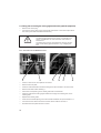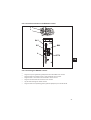
1
275
Spezialnähmaschine
mit Direktantrieb
Betriebsanleitung
D
Instruction manual
GB
Postfach 17 03 51, D-33703 Bielefeld • Potsdamer Straße 190, D-33719 Bielefeld
Telefon +49 (0) 521/ 9 25 - 00 • Telefax +49 (0) 521/ 9 25 24 35 • www.duerkopp-adler.com
Ausgabe / Edition:
02/2002
Änderungsindex
Rev. index: 00.0
Printed in Germany
Teile-Nr./Part.-No.:
0791 275740
Alle Rechte vorbehalten.
Eigentum der Dürkopp Adler AG und urheberrechtlich geschützt. Jede, auch
auszugsweise Wiederverwendung dieser Inhalte ist ohne vorheriges schriftliches
Einverständnis der Dürkopp Adler AG verboten.
All rights reserved.
Property of Dürkopp Adler AG and copyrighted. Reproduction or publication of the
content in any manner, even in extracts, without prior written permission of
Dürkopp Adler AG, is prohibited.
Copyright © Dürkopp Adler AG - 2002
Foreword
This instruction manual is intended to help the user to become
familiar with the machine and take advantage of its application
possibilities in accordance with the recommendations.
The instruction manual contains important information on how to
operate the machine securely, properly and economically.
Observation of the instructions eliminates danger, reduces costs
for repair and down-times, and increases the reliability and life of
the machine.
The instruction manual is intended to complement existing
national accident prevention and environment protection
regulations.
The instruction manual must always be available at the
machine/sewing unit.
The instruction manual must be read and applied by any person
that is authorized to work on the machine/sewing unit. This
means:
– Operation, including equipping, troubleshooting during the
work cycle, removing of fabric waste,
– Service (maintenance, inspection, repair and/or
– Transport.
The user also has to assure that only authorized personnel work
on the machine.
The user is obliged to check the machine at least once per shift
for apparent damages and to immediatly report any changes
(including the performance in service), which impair the safety.
The user company must ensure that the machine is only operated
in perfect working order.
Never remove or disable any safety devices.
If safety devices need to be removed for equipping, repairing or
maintaining, the safety devices must be
remounted directly after completion of the maintenance and
repair work.
Unauthorized modification of the machine rules out liability of the
manufacturer for damage resulting from this.
Observe all safety and danger recommendations on the
machine/unit! The yellow-and-black striped surfaces designate
permanend danger areas, eg danger of squashing, cutting,
shearing or collision.
Besides the recommendations in this instruction manual also
observe the general safety and accident prevention regulations!
General safety instructions
The non-observance of the following safety instructions can cause bodily injuries or damages to the machine.
1.
The machine must only be commissioned in full knowledge of the instruction
book and operated by persons with appropriate training.
2.
Before putting into service also read the safety rules and instructions of the
motor supplier.
3.
The machine must be used only for the purpose intended. Use of the machine
without the safety devices is not permitted. Observe all the relevant safety
regulations.
4.
When gauge parts are exchanged (e.g. needle, presser foot, needle plate, feed
dog and bobbin) when threading, when the workplace is left, and during
service work, the machine must be disconnected from the mains by switching
off the master switch or disconnecting the mains plug.
5.
Daily servicing work must be carried out only by appropriately trained persons.
6.
Repairs, conversion and special maintenance work must only be carried out by
technicians or persons with appropriate training.
7.
For service or repair work on pneumatic systems, disconnect the machine from
the compressed air supply system (max. 7-10 bar).
Before disconnecting, reduce the pressure of the maintenance unit.
Exceptions to this are only adjustments and functions checks made by
appropriately trained technicians.
8.
Work on the electrical equipment must be carried out only by electricians or
appropriately trained persons.
9.
Work on parts and systems under electric current is not permitted,
except as specified in regulations DIN VDE 0105.
10.
Conversion or changes to the machine must be authorized by us and made
only in adherence to all safety regulations.
11.
For repairs, only replacement parts approved by us must be used.
12.
Commissioning of the sewing head is prohibited until such time as the entire
sewing unit is found to comply with EC directives.
It is absolutely necessary to respect
the safety instructions marked by these signs.
Danger of bodily injuries !
Please note also the general safety instructions.
Contents
page:
Part 2: Installation instructions Cl. 275 direct drive
1.
Scope of delivery . . . . . . . . . . . . . . . . . . . . . . . . . . . . . .
7
2.
General and transport packing . . . . . . . . . . . . . . . . . . . . . .
7
3.
3.1
3.2
3.2.1
3.2.2
3.2.3
3.3
Assembling the stand . . . . . . . . . . . . . . . .
Assembling the stand parts . . . . . . . . . . . . . .
Completing the table top and fitting it to the stand.
Machines with no edge cutter . . . . . . . . . . . . .
Machines with an edge cutter . . . . . . . . . . . .
Machines with an edge cutter and fullness control
Setting the working height . . . . . . . . . . . . . . .
.
.
.
.
.
.
.
9
9
9
9
11
13
14
4.
4.1
Assembling the machine head . . . . . . . . . . . . . . . . . . . . . .
Fitting the machine head . . . . . . . . . . . . . . . . . . . . . . . . . .
15
15
5.
5.1
5.2
5.3
5.3.1
5.3.2
5.4
5.4.1
5.4.2
5.5
5.6
Sewing drive . . . . . . . . . . . . .
Items supplied . . . . . . . . . . . . .
Fitting the control . . . . . . . . . . .
Fitting the set-point generator . . .
All subclasses except 275-742642 .
Subclass 275-742642 . . . . . . . .
Fitting the knee-switch . . . . . . . .
All subclasses except 275-742642 .
Subclass 275-742642 . . . . . . . .
Fitting the cable conduit . . . . . . .
Fitting the pedal . . . . . . . . . . . .
.
.
.
.
.
.
.
.
.
.
.
16
16
16
16
16
17
17
17
17
17
17
6.
6.1
6.2
6.3
Electrical connection . . . . . . . . . . . . . . . . . . .
Checking the mains voltage . . . . . . . . . . . . . . . .
Earthing . . . . . . . . . . . . . . . . . . . . . . . . . . .
Fitting and connecting the sewing-light transformer
(optional equipment) . . . . . . . . . . . . . . . . . . . .
Connection to the DA220C control . . . . . . . . . . . .
Connection sockets on the DA220C control . . . . . .
Connecting the DA220C control . . . . . . . . . . . . .
Checking the direction of rotation of the sewing drive
Checking the positioning. . . . . . . . . . . . . . . . . .
Machine-specific parameters . . . . . . . . . . . . . . .
General . . . . . . . . . . . . . . . . . . . . . . . . . . . .
Autoselect . . . . . . . . . . . . . . . . . . . . . . . . . .
Master reset . . . . . . . . . . . . . . . . . . . . . . . . .
. . . . . . . . .
. . . . . . . . .
. . . . . . . . .
19
19
19
.
.
.
.
.
.
.
.
.
.
20
20
21
21
22
23
23
23
23
23
6.3.1
6.4
6.5
6.6
6.7
6.8
6.8.1
6.8.2
6.9
.
.
.
.
.
.
.
.
.
.
.
.
.
.
.
.
.
.
.
.
.
.
.
.
.
.
.
.
.
.
.
.
.
.
.
.
.
.
.
.
.
.
.
.
.
.
.
.
.
.
.
.
.
.
.
.
.
.
.
.
.
.
.
.
.
.
.
.
.
.
.
.
.
.
.
.
.
.
.
.
.
.
.
.
.
.
.
.
.
.
.
.
.
.
.
.
.
.
.
.
.
.
.
.
.
.
.
.
.
.
.
.
.
.
.
.
.
.
.
.
.
.
.
.
.
.
.
.
.
.
.
.
.
.
.
.
.
.
.
.
.
.
.
.
.
.
.
.
.
.
.
.
.
.
.
.
.
.
.
.
.
.
.
.
.
.
.
.
.
.
.
.
.
.
.
.
.
.
.
.
.
.
.
.
.
.
.
.
.
.
.
.
.
.
.
.
.
.
.
.
.
.
.
.
.
.
.
.
.
.
.
.
.
.
.
.
.
.
.
.
.
.
.
.
.
.
.
.
.
.
.
.
.
.
.
.
.
.
.
.
.
.
.
.
.
.
.
.
.
.
.
.
.
.
.
.
.
.
.
.
.
.
.
.
.
.
.
.
.
.
.
.
.
.
.
.
.
.
.
.
.
.
.
.
.
.
.
.
.
.
.
.
.
.
.
.
.
.
.
.
.
.
.
.
.
.
.
.
.
.
.
.
.
.
.
.
.
.
.
.
.
.
.
.
.
.
.
.
.
.
.
.
.
.
.
.
.
.
.
.
.
.
.
.
.
.
.
.
.
.
.
.
.
.
.
.
.
.
.
GB
Contents
7.
7.1
7.1.1
7.1.1.1
7.1.1.2
7.1.2
7.1.3
7.1.4
7.1.5
7.1.6
7.1.6.1
7.1.6.2
7.1.6.3
7.1.7
7.1.8
7.2
7.2.1
7.2.2
7.2.3
7.2.4
7.2.5
7.2.6
7.2.7
7.2.8
7.2.9
7.2.10
7.3
7.3.1
7.3.2
7.3.3
7.3.4
7.3.5
7.3.6
7.3.7
7.3.8
7.3.9
7.3.10
7.3.11
7.3.12
Operating and adjusting the DC1500/DA220C direct-current
positioning actuator . . . . . . . . . . . . . . . . . . . . . . . . . . . .
DA220C control operating and display elements . . . . . . . . . . . .
Changing parameter values at operator level with the DA220C control . . .
Calling and changing operator-level parameters one after the other
with the DA220C control . . . . . . . . . . . . . . . . . . . . . . . . . . .
Calling and changing operator-level parameters directly with the
DA220C control . . . . . . . . . . . . . . . . . . . . . . . . . . . . . . . .
Reducing the maximum speed with the DA220C control . . . . . . . .
DA220C control operator-level parameter list . . . . . . . . . . . . . .
Changing technician-level and manufacturer-level parameter values . .
Setting positions with the DA220C control . . . . . . . . . . . . . . . .
Setting machine-specific parameters with the DA220C control . . . .
General . . . . . . . . . . . . . . . . . . . . . . . . . . . . . . . . . . . . .
Autoselect . . . . . . . . . . . . . . . . . . . . . . . . . . . . . . . . . . .
Table of DA220C control machine-specific parameters . . . . . . . . .
Master reset with the DA220C control . . . . . . . . . . . . . . . . . . .
Condition and error messages . . . . . . . . . . . . . . . . . . . . . . .
V810 operating panel (optional equipment). . . . . . . . . . . . . . . .
Operating and display elements on the V810 operating panel . . . . .
Key functions on the V810 operating panel . . . . . . . . . . . . . . . .
Meaning of the symbols on the V810 operating panel . . . . . . . . .
Changing parameter values at operator level . . . . . . . . . . . . . .
Reducing the maximum speed . . . . . . . . . . . . . . . . . . . . . . .
Changing technician-level and manufacturer-level parameter values
with the V810 operating panel . . . . . . . . . . . . . . . . . . . . . . .
Setting positions with the V810 operating panel . . . . . . . . . . . . .
Setting machine-specific parameters with the V810 operating panel . . .
Master reset with the V810 operating panel . . . . . . . . . . . . . . .
Condition and error messages on the V810 operating panel. . . . . .
V820 operating panel. . . . . . . . . . . . . . . . . . . . . . . . . . . . .
Operating and display elements on the V820 operating panel . . . . .
Key functions on the V820 operating panel . . . . . . . . . . . . . . . .
Meaning of the symbols on the V820 operating panel . . . . . . . . .
Changing parameter values at operator level . . . . . . . . . . . . . .
Reducing the maximum speed . . . . . . . . . . . . . . . . . . . . . . .
Quick information and quick settings entry (HIT) . . . . . . . . . . . .
Changing technician-level and manufacturer-level parameter values
with the V820 operating panel . . . . . . . . . . . . . . . . . . . . . . .
Setting positions with the V820 operating panel . . . . . . . . . . . . .
Setting machine-specific parameters with the V820 operating panel . . .
Master reset with the V820 operating panel . . . . . . . . . . . . . . .
Condition and error messages on the V820 operating panel. . . . . .
Seam programming with the V820 operating panel . . . . . . . . . . .
page:
24
25
26
26
27
27
28
29
30
32
32
32
32
33
34
35
35
35
36
37
37
38
39
40
40
40
41
41
41
43
44
44
44
45
46
47
47
48
48
Contents
page:
8.
8.1
8.1.1
8.1.2
8.1.3
8.2
Fullness control in classes 275-142342 and 275-742642
Checking the basic control setting . . . . . . . . . . . . . . .
Adjusting the LED and display brightness . . . . . . . . . .
Moving to the reference position after each thread cut . . .
Activating the next seam sequence when the thread is cut
Rotation in the reference position . . . . . . . . . . . . . . .
.
.
.
.
.
.
49
49
49
49
50
50
9.
Pneumatic connection . . . . . . . . . . . . . . . . . . . . . . . . . . .
51
10.
Lubrication . . . . . . . . . . . . . . . . . . . . . . . . . . . . . . . . . .
52
11.
Sewing test . . . . . . . . . . . . . . . . . . . . . . . . . . . . . . . . . .
52
.
.
.
.
.
.
.
.
.
.
.
.
.
.
.
.
.
.
.
.
.
.
.
.
.
.
.
.
.
.
GB
Notes
GB
5
1
2
9
3
10
11
4
8
7
5
6
6
1. Scope of Delivery
What items are supplied depends on your order.
Before setting-up please check that all the required components are present.
Equipment (depending on subclass):
–
–
–
–
–
–
–
–
–
–
–
–
–
1
Reel stand
2
Table plate
3
Control with main switch
4
Maintenance unit
5
Pedal linkage
6
Pedal
7
Frame
8
Drawer
9
Upper part of the machine with sewing drive
10
Aattachment bracket for set-point generator (packed with the control)
11
Set-point generator (packed with the control)
Minor components in the accessory pack
Fullness control (depending on subclass)
GB
2. General and transport packing
CAUTION:
The special sewing machine must be set up by trained
specialist personnel.
Transport packing
If the special sewing machine you have bought is already set up, the following transport
packing must be removed:
–
safety straps and battens on the upper part of the machine, table and frame
7
1
15
14
14
13
2
3
12
11
10
4
9
8
5
6
7
8
3. Assembling the stand
3.1 Assembling the stand parts
– Assemble the frame components as shown in the illustration.
– Fit the four enclosed feet 6 to the frame.
– Slightly loosen screws 5 on both sides of the cross-brace 7 and make sure the
frame is firm and stable.
All four of the frame supports must be firmly on the ground.
–
–
Retighten screws 5.
Screw the oilcan holder 8 onto the left-hand upright of the frame.
3.2 Completing the table top and fitting it to the stand
3.2.1 Machines with no edge cutter
(classes 275-140332, 275-140342, 275-142342)
–
–
Fit the top support 15 into the hole in the table plate.
–
–
–
–
Fit the rest plug 13 and push on the pressure springs.
–
Attach the table plate 12 to the frame with wood screws (B8 x 35).
Its position on the frame can be seen from the dimensions in the sketch.
–
Fit the reel stand 1 into the hole in the table plate and attach with nuts and
washers.
Fit and align the yarn-reel holder and thread-guide arm.
The yarn-reel holder and thread-guide arm must be vertically aligned.
Fit the rubber rests 14 for the upper part of the machine into the recesses in the
table plate 12.
Screw on the drawer 11 with its brackets under the left-hand side of the table plate.
Screw on the cable conduit 10 under the back of the table plate.
1 0 0 m m
5 0 0 m m
Mark the positions of the screw connections of the oil collector 2 and attach it under
the table-plate opening with wood screws.
6 7 m m
1 0 6 0 m m
9
GB
1
15
14
14
13
2
3
12
11
10
4
9
8
5
6
7
10
3.2.2 Machines with an edge cutter
(classes 275-740642 and 275-742642)
–
–
Fit the top support 15 into the hole in the table plate.
–
–
–
–
Fit the rest plug 13 and push on the pressure springs.
–
Mark the positions of the screw connections of the waste chute 16 and attach it
under the table-plate opening with wood screws.
Screw the oil drip pan 2 and waste chute together.
–
Attach the table plate 12 to the frame with wood screws (B8 x 35).
Its position on the frame can be seen from the dimensions in the sketch
(see page 9).
–
Fit the reel stand 1 into the hole in the table plate and attach with nuts and
washers.
Fit and align the yarn-reel holder and thread-guide arm.
The yarn-reel holder and thread-guide arm must be vertically aligned.
Fit the rubber rests 14 for the upper part of the machine into the recesses in the
table plate 12.
Screw on the drawer 11 with its brackets under the left-hand side of the table plate.
Screw on the cable conduit 10 under the back of the table plate.
Mark the positions of the screw connections of the oil drip pan 2 and fix it under the
table-plate opening with wood screws.
GB
16
11
17
18
20
19
21
12
22
23
3.2.3 Machines with an edge cutter and fullness control
(class 275-742642)
(for items 1-16 see the preceding pages)
–
–
–
–
–
Attach items 1-16 as described in the previous section.
Fit the junction box 17 into item 23.
Fit the control 18 into item 22.
Fit the sewing-light transformer 19 into item 21.
Screw on the knee-switch 20 under the table top 1.
GB
13
3.3 Adjusting the working height
The working height can be adjusted between 750 and 950 mm (measured to the upper
edge of the table top).
–
–
Undo screws 1 on both legs of the stand.
–
Tighten both screws 1.
Adjust the table top vertically to the desired working height.
To prevent tilting, pull out the table top or push it in uniformly
on both sides.
1
14
4. Assembling the machine head
4.1 Fitting the machine head
CAUTION:
Remove the front and centre support screws before tilting
into the working position.
–
–
Fit the upper part of the machine 1, tilted, into the opening in the table top.
Remove the front and centre support screws 2.
1
2
GB
15
5. Sewing drive
1
2
5
6
7
8
9
10
3
4
7
2
3
11
5.1 Items supplied
DC1500/DA220C positioning actuator
–
–
–
–
–
–
–
DC1500 motor
DA220C control
EB301 A set-point generator
pedal linkage
attachment items
V810 operating panel (optional equipment)
V820 operating panel (optional equipment)
5.2 Fitting the control
– Fit the control 8 with 4 screws under the table top 5.
– Attach the mains cable of the control with its cleat under the table top.
5.3 Fitting the set-point generator
5.3.1 All subclasses except 275-742642
–
–
16
Screw on the bracket 2 under the table top 5 (see illustration above left).
Screw the set-point generator 3 onto the bracket 2 (see illustration above left).
5.3.2 Subclass 275-742642
With this subclass a large number of assemblies are fitted under the table top, so it is
essential to comply with the dimensional sketch in section 3.2.3.
–
–
Screw on the bracket 2 under the table top 5 (see illustration above right).
Screw the set-point generator 3 onto the bracket 2 (see illustration above right).
5.4 Fitting the knee-switch
5.4.1 All subclasses except 275-742642
–
Screw on the knee-switch 7 under the table top (illustration above left).
5.4.2 Subclass 275-742642
–
Screw on the knee-switch 7 under the table top (illustration above right).
5.5 Fitting the cable conduit
– Screw on the cable conduit 1 under the table top 5.
5.6 Fitting the pedal
– Attach the pedal 10 to the frame brace 11.
– For ergonomic reasons the lateral alignment of the pedal 10 should be such that
GB
the middle of the pedal is roughly beneath the needle.
The frame brace 11 is fitted with slots for pedal alignment.
–
Attach the pedal linkage 9 with ball sockets to the set-point generator 3 and
pedal 10.
–
–
Slightly undo screw 4.
–
Tighten screw 4.
Adjust the height of the pedal linkage:
when not under load the pedal must be at an angle of approx. 10°.
17
1
2
2
3
18
6. Electrical connection
CAUTION:
All work on the electrical equipment of this special sewing
machine may only be carried out by qualified electricians
who have undergone appropriate training.
The mains plug must be removed.
It is essential to comply with the sewing-drive
manufacturer’s operating instructions (supplied).
6.1 Checking the mains voltage
CAUTION:
The design voltage range for the sewing drive is 190-240V
50/60Hz. The mains voltage must be within this range. You
must ensure that the mains-cable fuse is rated no higher
than 16A (see data sheet 9800 331101 DAT).
CAUTION:
The machine must be connected to the mains by a plug
connection.
6.2 Earthing
GB
The earth cable 2 (in the accessory pack) takes static charges from the upper part of the
machine to earth (control housing).
–
–
–
Attach the earth cable 2 to the motor with screw 3.
Lay the earth cable.
Screw the cable lug of the earth cable 2 onto the control 1 with the screw.
19
6.3 Fitting and connecting the sewing-light transformer (optional equipment)
– Remove the mains plug.
– Connect the mains cable of the sewing-light transformer to the mains-input side in
the control (see data sheet 9800 331101 DAT).
CAUTION:
The sewing-light transformer is directly connected to the
mains. It is therefore live even when the main switch is
switched off.
The mains plug must be removed before carrying out any
work on the sewing-light transformer, e.g. changing the
fuse.
6.3.1 Connection to the DA220C control
1
2
–
–
–
–
–
–
Undo 4 screws on the front plate of the control.
–
–
–
–
Replace the rubber guide.
20
3
4
5
6
Remove the front plate.
Push the cable forwards from behind through the cable conduit 2 into the control.
Remove the black rubber bushing 1.
Pierce the round opening in the rubber guide with a screwdriver.
Pass the cable of the sewing-light transformer through the resulting hole in the
rubber guide.
Press on the terminal opening 5 or 6 with a small screwdriver to open terminal 3 or 4.
Connect the blue cable to terminal 3 and the brown cable to terminal 4.
Re-attach the front plate with the 4 screws.
6.4 Connection sockets on the DA220C control
1
2
B41
B 4 1
M
B80
B2
B 2
B 8 0
M
E B ...
A
B 1 8
B 7 7 6
L S M ...
V 8 . .
B776
A
GB
6.5 Connecting the DA220C control
–
–
–
–
–
–
Plug the set-point generator (pedal) lead into socket B80 of the control.
Plug the lead of the motor sensor 2 into socket B2 of the control.
Plug the lead 1 of the motor into socket B41 of the control.
Plug the machine lead into socket A of the control.
Lay all leads through the cable conduit.
Plug the lead of the operating panel (optional equipment) into socket B776.
21
6.6 Checking the direction of rotation of the sewing drive
CAUTION:
Before the special sewing machine is started it is essential
to check the direction of rotation of the sewing drive.
Switching it on can cause damage if the direction of rotation
is incorrect.
The arrow on the belt guard indicates the correct direction of rotation.
The direction of rotation of the direct-current positioning actuator is set to run from right
to left by the pre-set value of the relevant parameter in the control. Even so, the
direction of rotation must be checked before the machine is started. A possible
procedure is as follows:
First lock the sewing foot in the up position
(see Operating instructions, section 6.13).
DA220C control
–
The plugs of the set-point generator, motor, motor sensor and operating panel
(if present) must be plugged in (see section 6.5).
–
–
Unplug the 37-pin plug of the upper part of the machine.
–
–
Press the pedal slightly forwards; the drive turns: check the direction of rotation.
–
–
Turn off the main switch.
22
Turn on the main switch.
The operating panel shows “Inf A5” or “A5”, which means that no valid Autoselect
resistance has been detected and the maximum speed will therefore be limited.
If the direction of rotation of the drive is incorrect, parameter 161 at “technician
level” must be set to 1. See section 7.1.4.
Plug in the 37-pin plug of the upper part of the machine.
6.7 Checking the positioning
Needle positions are correctly set prior to delivery, but they should still be checked
before starting the machine.
NB:
The sewing foot must be locked in the up position (see Operating instructions,
section 6.13).
The machine must move to an intermediate halt in position 1 (needle down).
See section 7.1, LED 7.
Position 1
–
–
Turn on the main switch.
–
Check the position of the needle.
Briefly push the pedal forwards and return it to its original position. The needle
moves to position 1 = handwheel point “F”.
Position 2
–
–
–
Move the pedal forwards, then fully back.
The needle moves to position 2 = handwheel point “C”.
Check the position of the needle.
If either or both needle positions are incorrect, they must be corrected:
see section 7.1.5 or 7.2.7.
GB
6.8 Machine-specific parameters
6.8.1 General
The functions of the sewing-drive control are determined by the program and the
parameter settings.
All parameter values for the relevant machine class and subclass are correctly set prior
to delivery. This entails changing some pre-set control values (e.g. the maximum
speed). If the control is replaced, the machine-specific parameters must be restored to
their correct values. See section 7.1.6, 7.2.8 or 7.3.9.
6.8.2 Autoselect
The control “recognises” which machine series is connected by measuring the
Autoselect resistance in the machine. Autoselect selects control functions and the
pre-set parameter values.
Caution: If the control fails to recognise a valid Autoselect resistance (or any at all), the
drive runs only with the so-called emergency operating functions to prevent machine
damage.
6.9 Master reset
A master reset (see section 7.1.7, 7.2.9 or 7.3.10) resets all parameters to their pre-set
values. After a master reset the machine-specific parameters must be restored to their
correct values. See section 7.1.6, 7.2.8 or 7.3.9.
23
7. Operating and adjusting the DC1500/DA220C
direct-current positioning actuator
Operation
The DA220C control contains all operating components necessary to switch functions
and set parameters. It can be operated without an operating panel, but seam
programming is not possible.
The V810 and V820 operating panels (optional equipments) can also be connected to
the control. Seam programming can be carried out with the V820 operating panel.
A detailed description of the control can be found in the
“EFKA DC1500/DA220C control 5300” operating instructions.
DA220C control functions
The functions of the DA220C control are determined by the program and the parameter
settings. With the correct parameter settings the control is ideally matched to the class
and subclass of the machine. The parameter values are pre-set in the controls. For
each class and subclass some parameters must be changed from their pre-set values.
All parameters are correctly set prior to delivery.
Access authorisation for command entry
To prevent the unwanted alteration of pre-set functions there are three levels of
command entry.
Access:
- the operator at “operator level” with no code
- the technician at “technician level” and “operator level” with a code.
- the manufacturer at “manufacturer level” and all lower levels with a code.
24
7.1 DA220C control operating and display elements
LED 1
P
E
+
LED 8
> >
GB
Key
P
E
+
-
>>
Key
Function in sewing mode (main switch on)
enter / leave programming mode
starting bar tack single / double / off
(displayed by LED1 and LED2)
ending bar tack single / double / off
(displayed by LED3 and LED4)
automatic sewing-foot lift on halt in seam on/off
(displayed by LED5)
automatic sewing-foot lift after thread cut on/off
(displayed by LED6)
basic needle position: position 1 (displayed by LED7)
or position 2 (displayed by LED8)
P
E
+
-
Function in programming mode
(see section 7.1.1)
enter / leave programming mode
call parameter value or confirm change
increase number or parameter value
reduce number or parameter value
>>
Shift function
25
LED1
LED2
LED1
LED3
LED4
LED3
LED5
LED6
LED7
LED8
LED
on display for
on display for
and LED2 off
on display for
on display for
and LED4 off
on display for
on display for
on display for
on display for
Function
single starting bar tack
double starting bar tack
starting bar tack off
single ending bar tack
double ending bar tack
ending bar tack off
automatic sewing-foot lift on halt in seam
automatic sewing-foot lift after thread cut.
basic needle position = down
basic needle position = up
display 3-figure display for rpm, parameters and code
7.1.1 Changing parameter values at operator level with the DA220C control
Operator-level parameter values (see parameter list in section 7.1.3) can be changed
without entering a code.
7.1.1.1 Calling and changing operator-level parameters one after the other with
the DA220C control
–
–
–
–
–
–
–
–
Turn on the main switch.
–
–
Press “P”: the same parameter, “0.0.1.”, is displayed.
–
On termination of programming at operator level the changed values are saved.
26
The value for the maximum speed appears in the display, e.g. “480” for 4800 rpm.
Press “P”: the first parameter, “0.0.0.”, is displayed.
Press “E”: its associated parameter value, e.g. “002”, is displayed.
Press “+”: the parameter value is increased.
Press “-”: the parameter value is reduced.
Press “E”: the next parameter, “0.0.1.”, is displayed.
Press “E”: the value of parameter “0.0.1.”, e.g. “004”, is displayed, and so on.
In this way all the operator-level parameters can be displayed and changed one
after the other. After the last parameter programming at operator level terminates.
You can leave programming at operator level at any time:
Press “P” again to leave programming at operator level. The value for the maximum
speed appears in the display, e.g. “480” for 4800 rpm.
7.1.1.2 Calling and changing operator-level parameters directly with the
DA220C control
–
–
–
–
–
–
–
–
–
–
–
–
–
–
–
Turn on the main switch.
The value for the maximum speed appears in the display, e.g. “480” for 4800 rpm.
Press “P”: the first parameter, “0.0.0.”, is displayed.
Press “>>”: the first figure of the parameter flashes, “0.0.0.”
Press the “+” or “-” keys to change the value of the flashing figure.
Press “>>”: the second figure of the parameter flashes, “0.0.0.”
Press the “+” or “-” keys to change the value of the flashing figure.
Press “>>“: the third figure of the parameter flashes, “0.0.0.”
Press the “+” or “-” keys to change the value of the flashing figure.
The required parameter is set.
Press “E”: the value of the set parameter is displayed, e.g. “on”.
Press “-” to switch from “on” to “oFF”.
Press “+” to switch from “oFF” to “on”.
Press “E”: the next parameter is called.
Once a parameter has been set the next one can be called and changed, or
programming terminated by pressing “P”. The value for the maximum speed
appears in the display, e.g. “480” for 4800 rpm.
7.1.2 Reducing the maximum speed with the DA220C control
The maximum speed can be reduced to adapt it to particular applications.
During sewing, and if the machine halts, the maximum speed is shown in the display.
The three-figure value displayed must be multiplied by 10. While it is displayed the
maximum speed can be changed by pressing the “+ / -” keys. The adjustment range lies
between the values of parameters F-111 (maximum) and F-121 (minimum). See
sections 7.1.4 and 7.1.6.
NB: there are two settings for the maximum speed, the value of parameter 111 and the
reduction in maximum speed with the “+/-” keys. The lower value always has priority. If
the maximum speed is reduced with the “+/-” keys, an increase in the value of
parameter 111 takes effect only if the reduction is cancelled during sewing by pressing
the “+” key.
Caution: the maximum speed (the value of parameter 111) should not be set higher
than the figure shown in the parameter sheet (in the accessory kit) for machines of the
relevant class and subclass.
27
GB
7.1.3 DA220C control operator-level parameter list
Parameter
adjustment range
pre-set value
No.
000 c2
Abb.
Name/Function
starting-bar-tack stitches forwards
min max
0
254
100R
2
001 c1
starting-bar-tack stitches backwards
0
254
4
002 c3
ending-bar-tack stitches backwards
0
254
3
003 c4
ending-bar-tack stitches forwards
0
254
3
004 LS
number of light-barrier equalising stitches
(large stitch length)
number of light-barrier filter stitches for
knits
number of seams terminated with
the light barrier
number of stitches in the
automatically-produced seam section
assigning a function to key 9 (on the
V820 operating panel)
1 = Softstart ON/OFF
2 = ornamental-stitch bar tack ON/OFF
3 = stroke adjustment
press and release = ON /
press and hold = OFF
4 = needle cooling ON/OFF
light barrier ON/OFF
number of light-barrier equalising stitches
(small stitch length)
thread cutter ON/OFF
thread retractor ON/OFF
stitch count ON/OFF
number of stitches, starting
decorative-stitch bar tack forwards
SAr
number of stitches, starting
decorative-stitch bar tack backwards
number of stitches, ending
decorative-stitch bar tack forwards
number of stitches, ending
decorative-stitch bar tack backwards
0
254
4
0
254
0
0
15
1
0
254
10
1
5
2
1
0
0
5
1
254
2
0
8
0
0
0
0
1
1
1
254
1
0
0
3
0
254
3
0
254
3
0
254
3
005LSF
006LSn
007 Stc
008 -F-
009 LS
010cLS
013 FA
014FW
015StS
080Sav
081
082SEr
083SEv
28
7.1.4 Changing technician-level and manufacturer-level parameter values
CAUTION:
Great care must be taken when changing parameter values,
as an incorrectly-set drive control may damage the
machine.
NB:
A master reset restores all parameters to the values pre-set by the drive manufacturer.
See section 7.1.7.
Entering the technician-level code with the DA220C control
–
–
–
–
–
–
Turn off the main switch.
–
Press the “E” key: the first technician-level parameter, “1.0.0.”, is displayed.
Press and hold down the “P” key.
Turn on the main switch: “cod” appears in the display.
Release the “P” key.
Press the “>>“ key: “000” appears in the display. The left-hand figure flashes.
Enter code 190. Press the “+” or “-” keys to change the value of the flashing figure.
Press the “>>“ key to move to the next figure.
GB
Selecting parameters and changing values
–
Use the “+”, “-” and “>>” keys to set the required parameter
(see section 7.1.1.2).
–
–
–
Press the “E” key: the value of the parameter is displayed.
Press the “+” or “-” keys to change the value of the parameter.
Press the “E” key to display the next parameter or the “P” key
to display the same parameter.
Saving changed parameter values
–
–
Press the “P” key to end programming.
–
–
If no seam is commenced, the change is lost.
Sew a complete seam, i.e. push the pedal forwards, then all the way back: the
change is saved.
Press the “P” key again to return to programming level.
29
Entering the manufacturer-level code with the DA220C control
–
–
–
–
–
Turn off the main switch.
–
–
Press the “E” key: the first manufacturer-level parameter, “2.0.0.”, is displayed.
Press and hold down the “P” key.
Turn on the main switch: “Cod” appears in the display.
Release the “P” key.
Enter code 311. Press the “+” or “-” keys to change the value of the flashing figure.
Press the “>>” key to move to the next figure.
Continue as described under “Selecting parameters and changing values”.
CAUTION:
The changed parameter values are not saved unless a
complete seam is sewn after leaving the programming
level, i.e. the pedal is pushed forwards and then all the way
back.
If the drive is switched off straight after leaving the
programming level, the changes are lost.
7.1.5 Setting positions with the DA220C control
Setting the reference position
Prerequisite:
The technician-level code has been set (see section 7.1.4).
–
–
–
–
–
Press the “E” key: the first technician-level parameter, 1.0.0., is displayed.
–
Press the “P” key: the reference position is saved. The current parameter number
is displayed.
–
Press the “P” key to terminate technician-level programming.
30
Use the “+”, “-” and “>>“ keys to enter parameter 1.7.0..
Press the “E” key: “Sr1” appears in the display.
Press the “>>“ key: “P o” appears in the display (the “o” character rotates).
Turn the handwheel in the normal direction of rotation until the rotating character
“o” in the display goes out, then turn it further until the handwheel reaches its
reference position (position “F”).
Setting positions 1 and 2
Prerequisite:
The reference position has been set (see section 7.1.5, “Setting the reference
position”).
NB:
The position values are pre-set, so there is normally no need to set them. The pre-set
values (see the parameter sheet in the accessory kit) are equivalent to the number of
increments after the reference position (in the correct direction of rotation). One
revolution of the motor shaft is equal to one revolution of the handwheel , equivalent to
512 increments.
The positions are:
P1E = handwheel at point “F” = position 1.
P2E = handwheel at point “C” = position 2.
P1A = about 100 increments after P1E (important for internal control functions).
P2A = about 100 increments after P2E (important for internal control functions).
If the positions have to be reset, proceed as follows:
–
After entering the technician-level code (see section 7.1.4):
Press the “E” key: the first technician-level parameter, 1.0.0., is displayed.
–
–
–
–
Use the “+”, “-” and “>>“ keys to enter parameter “1.7.1.”.
–
–
Press the “E” key: “P2E” appears in the display.
–
–
Press the “E” key. “P1A” appears in the display.
–
–
Press the “E” key: “Sr2” appears in the display.
Press the “>>“ key: “P1E” appears in the display.
Turn the handwheel in the correct direction until “P1E” in the display changes to
increments. Turn the handwheel to point “F” (position 1E).
GB
Turn the handwheel in the correct direction until “P2E” in the display changes to
increments. Turn the handwheel to point “C” (position 2E).
Turn the handwheel in the correct direction until “ P1A” in the display changes to
increments. Turn the handwheel about 100 increments beyond position “P1E” to
position “P1A”.
Press the “E” key: “P2A” appears in the display.
Turn the handwheel in the correct direction until “ P2A” in the display changes to
increments. Turn the handwheel about 100 increments beyond position “P2E” to
position “P2A”.
–
Press the “P” key twice to terminate position setting and leave the programming
level.
–
Check the positions: see section 6.7.
NB:
If position checking establishes that, for example, positions 1 and 2 are being “overrun”
by about the same amount with respect to the setting, the reference position can be
advanced by this amount.
31
7.1.6 Setting machine-specific parameters with the DA220C control
7.1.6.1 General
The sewing-drive control functions are determined by the program and the parameter
settings.
Parameter values are pre-set by the drive manufacturer prior to delivery. For each class
and subclass a number of technician-level or even manufacturer-level parameters must
be changed so that the control exactly matches the machine. The relevant parameters
are listed in table 7.1.6.3 and the parameter sheet (see table 7.1.6.2). The parameter
sheet is in the accessory kit. All parameters are correctly set by Dürkopp Adler prior to
delivery.
7.1.6.2 Autoselect
The control “recognises” which machine series is connected by measuring the
Autoselect resistance in the machine. Autoselect selects control functions and the
pre-set parameter values. If the control fails to recognise a valid Autoselect resistance
(or any at all), the drive runs only with the so-called emergency operating functions to
prevent machine damage (see “EFKA DA220C 5300” operating instructions).
Autoselect
resistance
100R (100 ohms)
classes control
sewing drive
275
DA220C
parameter sheet
9800 331101 PB11
7.1.6.3 Table of DA220C control machine-specific parameters
The values of the parameters listed below must be changed from their pre-set values.
The values to be set (x) can be found in the 9800 331101 PB11 parameter sheet (in
the machine’s accessory kit).
Parameter
*
Name
F-111
F-250
F-251
T
A
A
F-252
F-255
A
A
275275275275140342 142342 740642 742642
140332
upper limit for maximum speed
function module for output A **x
output A and LED A after
x
x
x
x
thread cut **
output A inverted? 0=no, 1=yes **
function module for output B **
x
F-256
A
output B and LED B after
F-282
A
F-283
A
F-289
A
thread cut **
cut-out switch function
0=closing, 1=opening
cut-out function
0 = off
1 = cut-out 1 with no positioning
2 = cut-out 2 with positioning
rpm limit DB3000 for
x
manual bar tack
x
x
x
* T = technician-level parameters, A = manufacturer-level parameters.
32
x
x
x
** A function module is a part of the control that handles one of the machine’s facilities,
e.g. raising and lowering the transport roller. The control contains two function modules,
A and B.
Each function module has the following hardware:
–
–
–
one output (A or B), e.g. to control a solenoid valve
one input ( A or B), e.g. to connect a key
one output for an LED (A or B), e.g. displaying a switch status.
Each function module can be assigned various functions by the software. Each function
module has additional parameters, e.g. to activate counts or switch functions after the
thread is cut.
CAUTION:
Great care must be taken when changing parameter values,
as an incorrectly-set drive control may damage the
machine.
7.1.7 Master reset with the DA220C control
Any parameters that have been changed are restored to their pre-set values by a master
reset.
–
–
–
–
–
–
–
–
–
–
Turn off the main switch.
Press the “P” key, hold it down and turn on the main switch until “C.o.d.” appears.
Release the “P” key.
Enter the technician-level code. See section 7.1.4.
Press the “E” key: the parameter “1.0.0.” is displayed.
Press the “E” key: the value of parameter “1.0.0.” is displayed.
Set the value to 170.
Press the “P” key twice.
Turn off the main switch.
After a brief pause, turn the main switch on again. All parameters except 1.1.1.,
1.6.1., 1.7.0., 1.7.1. and 1.9.0. to 1.9.3., have been restored to their pre-set values.
CAUTION:
A few parameters, such as 1.7.0. (reference position),
1.7.1. (needle position) and 1.6.1. (direction of motor
rotation) are unaffected by a master reset.
After a master reset all machine-specific parameters
must be readjusted in accordance with the parameter
sheet. See section 7.1.6.
33
GB
7.1.8 Condition and error messages
General information
DA220C V810
A1
InF A1
A2
V820
InFo A1
A3
“StoP” flashes
+ Symbol
“cut-out”
InF A3
InFo A3
A5
InF A5
InFo A5
Meaning
The pedal is not in its zero position
when the sewing drive is switched on
“StoP” flashes The cut-out is active
The reference position is not set.
For programming see sections 7.1.5, 7.2.7
and 7.3.8.
No valid Autoselect resistance has been
detected.
Emergency-operation function:
for information see section 6.8.2.
Programming error messages (parameters)
If an incorrect code or parameter is entered, the following error message appears
(depending on the operating panel used):
DA220C
returns to “000” or the last parameter number
V810
returns to “0000” or the last parameter number
V820
as with V810, plus display “InF F1”
Hardware and software error messages
DA220C V810
E2
InF E2
V820
InF E2
E3
InF E3
InF E3
E4
InF E4
InF E4
h1
InF h1
InF h1
h2
InF h2
InF h2
34
Meaning
Mains voltage too low or time between
main switch OFF and main switch ON too brief.
Machine blocked or not reaching the
required rpm
Control problem due to defective earthing
or faulty plug connections (contact faults).
The commutating-transducer lead is defective or
the power electronics that generate the
rotating field are faulty.
Processor faulty.
7.2 V810 operating panel (optional equipment)
7.2.1 Operating and display elements on the V810 operating panel
7.2.2 key functions on the V810 operating panel
Functions can be turned on and off by briefly pressing the keys on the operating panel.
The functions are effective on machine only if the relevant devices (e.g. magnetic or
electro-pneumatic sewing-foot lift) are present.
Key
Function
1
double starting bar tack on
starting bar tack on
single starting bar tack on
Display
right arrow above the key on
both arrows on
left arrow above the key on
2
double ending bar tack on
ending bar tack on
single ending bar tack on
right arrow above the key on
both arrows on
left arrow above the key on
3
auto.
auto.
auto.
auto.
4
basic needle position = down
basic needle position = up
left arrow above the key on
right arrow above the key on
A
suppress bar tack or invoke bar tack
if starting or ending bar tack is switched on,
pressing the key switches the next bar tack off
if starting or ending bar tack is switched off,
pressing the key switches the next bar tack on
no display
foot
foot
foot
foot
lift
lift
lift
lift
on halt in seam
on halt in seam
after thread cut
after thread cut
on
on
on
on
GB
left arrow above the key on
left arrow above the key on
right arrow above the key on
right arrow above the key on
35
Symbol
Function
Display
B
needle up/down
no display
or shift function in programming mode
pressing this key executes a needle movement
that can be programmed with parameter 140.
See the parameter list in the Set-up instructions.
this key has a different function in
programming mode. See section 7.2.6
P
programming mode on/off
parameter number/standard display
See sections 7.2.4 and 7.2.6
E
switch from parameter number to
parameter number/parameter value
parameter value
confirmation of parameter value and
switch to the next parameter
See section 7.2.4 and 7.2.6.
+
increase the valued displayed in
display value is increased
programming mode
reduce the valued displayed in
display value is reduced
programming mode
7.2.3 Meaning of the symbols on the V810 operating panel
Symbol
Function
C
automatic rpm effective
only with seam sections
processed automatically
D
light barrier switched on
E
sewing drive switched on
F
rpm limit effective
G
bobbin-thread monitor switched on
36
Display
symbol on
symbol on
symbol on
symbol on
symbol flashes when
bobbin is running out
7.2.4 Changing parameter values at operator level
The operator-level parameters are given in the parameter list in section 7.1.3.
–
–
–
–
–
–
Turn on the main switch.
Press the “P” key: the first operator-level parameter, F-000, is displayed.
Press the “+” or “-” keys to call the next or preceding parameter.
Press the “E” key: the value of the selected parameter is displayed.
Press the “+” or “-” keys to change the value of the parameter.
Press the “E” key to save the change and display the next parameter, or
the “P” key to save the change and leave the programming level.
CAUTION:
The changed parameter values are not saved unless a
complete seam is sewn after leaving the programming
level, i.e. the pedal is pushed forwards and then fully back.
If the drive is switched off straight after leaving the
programming level, the change is lost.
GB
7.2.5 Reducing the maximum speed
The maximum speed can be reduced to adapt it to particular applications.
During sewing the control type “dA220C” is constantly shown in the display. Press the
“+” or “-” keys to display the maximum speed, and also to change it. The adjustment
range lies between the values of parameters F-111 (maximum value) and F-121
(minimum value).
NB:
There are two settings for the maximum speed, the value of parameter 111 and the
reduction in maximum speed with the “+/-” keys. The lower value always has priority. If
the maximum speed is reduced with the “+/-” keys, an increase in the value of
parameter 111 takes effect only if the reduction is cancelled.
CAUTION:
The maximum speed (the value of parameter 111) should
not be set higher than the figure shown in the parameter
sheet (in the accessory kit) for machines of the relevant
class and subclass.
37
7.2.6 Changing technician-level and manufacturer-level parameter values with
the V810 operating panel
Entering the technician-level code
–
–
–
–
–
–
–
Turn off the main switch.
All plugs on the sewing-drive control must be plugged in.
Press and hold down the “P” key.
Turn on the main switch: “C-0000” appears in the display.
Release the “P” key.
Enter code 1907. Press the “+” or “-” keys to change the value of the flashing
figure. Press the “>>” key to move to the next figure.
Press the “E” key: the first technician-level parameter, “F-100”, is displayed.
Selecting parameters and changing values
–
–
–
–
–
Press the “+” or “-” keys to select the next or previous parameter.
Parameters can be directly entered with the “>>”, “+” or “-” keys.
Press the “E” key: the value of the selected parameter is displayed.
Press the “+” or “-” keys to change the value of the parameter.
Press the “E” key to display the next parameter or key “P” to display the same
parameter.
Saving changed parameter values
–
–
Press the “P” key to end programming.
–
–
If no seam is sewn, the change is lost.
Sew a complete seam by pushing the pedal forwards and then all the way back.
The change is saved.
Press the “P” key again to return to the programming level.
Entering the manufacturer-level code
–
–
–
–
–
–
–
–
38
Turn off the main switch.
All plugs on the sewing-drive control must be plugged in.
Press and hold down the “P” key.
Turn on the main switch: “C-0000” appears in the display.
Release the “P” key.
Enter code 3112. Press the “+” or “-” keys to change the value of the flashing
figure. Press the “>>“ key to move to the next figure.
Press the “E” key: the first manufacturer-level parameter, F-200, is displayed.
Continue as described under “Selecting parameters and changing values”.
CAUTION:
The changed parameter values are not saved unless a
complete seam is sewn after leaving the programming
level, i.e. the pedal is pushed forwards and then all
the way back.
If the drive is switched off straight after leaving the
programming level, the changes are lost.
7.2.7 Setting positions with the V810 operating panel
Setting the reference position
Prerequisite:
The technician-level code has been entered. See section 7.2.6.
–
–
–
–
–
Press the “E” key: the first technician-level parameter, “F-100”, is displayed.
–
Press the “P” key: the reference position is saved and the current parameter
number is displayed.
–
–
If the error message “A3” is displayed, the setting must be repeated.
Use the “+”, “-” and “>>” keys to set the “F-170” parameter.
Press the “E” key: “Sr1 (o)” appears in the display.
Press the “>>“key: “PoS0 o” appears in the display (the o character rotates).
Turn the handwheel in the normal direction of rotation until the rotating character
“o” in the display goes out, then turn it further until the reference position is
reached (turn the handwheel to point “F”).
GB
Press the “P” key to terminate programming at technician level.
Settings positions 1 and 2
Prerequisite:
The reference position has been set and the technician-level code has been entered
(see above).
–
–
–
Enter the parameter “F-171”.
–
Correct the parameter value * if necessary, either with the “+” or “-” keys or by
turning the handwheel to point “F”.
–
Press the “E” key: “P2E xxx” appears in the display (xxx = parameter value of
position 2E).
–
Correct the parameter value * if necessary, either with the “+” or “-” keys or by
turning the handwheel to point “C”.
–
Press the “E” key: “P1A xxx” appears in the display (xxx = parameter value of
position 1A).
–
Correct the parameter value * if necessary, either with the “+” or “-” keys or by
turning the handwheel.
–
Press the “E” key: “P2A xxx” appears in the display (xxx = parameter value of
position 2A).
Press the “E” key: “Sr2 (o)” appears in the display.
Press the “>>”key: “P1E xxx” appears in the display (xxx = parameter value of
position 1E).
39
–
Correct the parameter value * if necessary, either with the “+” or “-” keys or by
turning the handwheel.
–
Press the “P” key twice to leave the programming level when the settings are
complete.
–
Check the positions: see section 6.7.
* NB:
The parameter values for positions 1E, 2E, 1A and 2A can be found in the parameter
sheet (accessory kit).
NB:
If position checking establishes that, for example, positions 1 and 2 deviate from the
required handwheel point by about the same angle, the problem can be solved by
altering the reference position by this angle.
7.2.8 Setting machine-specific parameters with the V810 operating panel
Machine-specific parameters can be set with the V810 operating panel. They are given
in section 7.1.6 and in the parameter sheet (in the accessory kit). The process is
described in section 7.2.6.
7.2.9 Master reset with the V810 operating panel
Any parameters that have been changed are restored to their pre-set values by a master
reset.
–
–
–
–
–
–
–
–
–
–
Turn off the main switch.
Press the “P” key, hold it down and turn on the main switch.
Release the “P” key.
Enter the technician-level code. See section 7.2.6.
Press the “E” key: the parameter “F-100” is displayed.
Press the “E” key: the value of parameter “F-100” is displayed.
Set the value to “170”.
Press the “P” key twice.
Turn off the main switch.
After a brief pause, turn the main switch on again. All parameters except 111, 161,
170, 171 and 190 to 193 have been restored to their pre-set values.
CAUTION:
A few parameters, such as F-170 (reference position),
F-171 (needle position) and F-161 (direction of motor
rotation) are unaffected by a master reset.
After a master reset all machine-specific parameters
must be readjusted in accordance with the parameter
sheet. See section 7.2.8.
7.2.10 Condition and error messages on the V810 operating panel
See section 7.1.8
40
7.3 V820 operating panel (optional equipment)
7.3.1 Operating and display elements on the V820 operating panel
7.3.2 Key functions on the V820 operating panel
Functions can be turned on and off by briefly pressing the keys on the operating panel.
The functions are effective on machine only if the relevant devices (e.g. magnetic or
electro-pneumatic sewing-foot lift) are present.
Key Function
1
double starting bar tack on
starting bar tack on
single starting bar tack on
2
stitch count, backwards seam
stitch count on
stitch count, forwards seam
3
light-barrier function “light - dark”
= switch from: “no material available”
to “material available”.
light barrier on
light-barrier function “dark - light”
= switch from: “material available” to
“no material available”.
4
double ending bar tack on
ending bar tack on
single ending bar tack on
5
thread cutter on
thread retractor on
thread cutter and thread retractor on
thread cutter and thread retractor off
6
auto. foot lift on halt in seam on
auto. foot lift on halt in seam on
auto. foot lift after thread cut on
auto. foot lift after thread cut off
GB
Display
right arrow above the key on
both arrows on
left arrow above the key on
right arrow above the key on
both arrows on
left arrow above the key on
right arrow above the key on
both arrows on
left arrow above the key on
right arrow above the key on
both arrows on
left arrow above the key on
left arrow above the key on
right arrow above the key on
both arrows on
both arrows off
left arrow above the key on
left arrow above the key on
right arrow above the key on
right arrow above the key off
41
Key Function
7
basic needle position = down
basic needle position = up
8
residual-thread monitor on
the function of the residual-thread monitor
can be changed with the parameter 195
(see Efka parameter list)
9
function key
the function of the key can be changed with
parameter F-008 (see parameter list,
section 7.1.3)
1 = Softstart ON/OFF
2 = ornamental-stitch bar tack ON/OFF
3 = stroke adjustment
function of the knee-switch or key:
“press and release” = ON /
“ press and hold” = OFF
4 = needle cooling ON/OFF
0
teach in or
run the saved sewing program
see programming instructions in the operating
instructions
EFKA DA220C 5300
A
suppress or invoke bar tacks
if the starting or ending bar tack is switched on,
pressing the key switches the next bar tack off
if the starting or ending bar tack is switched off,
pressing the key switches the next bar tack on
B
needle up/down
or Shift function in programming mode
pressing this key executes a needle movement
that can be programmed with parameter 140.
See the Efka parameter list. In programming
mode this key has a different function.
See section 7.3.8
programming mode on/on
see sections 7.3.4 and 7.3.7
switch from parameter number to
parameter value.
Confirm parameter value and
switch to next parameter.
See sections 7.3.4 and 7.3.7
increase the value displayed
in programming mode
reduce the value displayed
in programming mode
P
E
+
-
42
Display
left arrow above the key on
right arrow above the key on
xxxx
--I I--
SSt ON*/OFF < — > SSc xxx
SrS ON*/OFF
hPr ON*/OFF
nh ON*/OFF
* when ON the left arrow above
the key is switched on
program number
seam-section number
seam-section stitch number
number of stitches after
light-barrier detection
no display
no display
parameter number/standard display
parameter number/parameter value
displayed value is increased
displayed value is reduced
7.3.3 Meaning of the symbols on the V820 operating panel
Symbol
Function
C
abbreviation for code
D
abbreviation for parameter number
E
program number in teach-in mode
F
seam-section number in teach-in mode
G
H
cut-out active
entry via keys blocked
I
error message
J
entering number of stitches in teach-in mode
K
bobbin-thread monitor on
L
rpm limit effective
M*
right needle switched off
N
O
P
equalising stitches for light barrier
machine running
automatic rpm effective
Q*
left needle switched off
Display
symbol on when a code is
displayed, e.g. C 1907
symbol on when a parameter
number is displayed, e.g. F-111
symbol on when the program
number of a sewing program
is displayed
symbol on when a sewingprogram seam-section number
is displayed
symbol flashes on active cut-out
symbol on when entry via
keys is blocked
symbol on (for fault list see
section 7.1.8)
symbol on when the number
of stitches in a seam section
is displayed
symbol flashes when bobbin is
running out only on machines
with a residual-thread monitor
symbol on when one of the
possible rpm limits is effective
symbol on when right
needle bar is switched off.
only on machines with automatic
needle-bar switch-off
symbol on
symbol on
symbol on when a seam section
in a sewing program is being
automatically executed
at constant rpm
symbol on when left needle bar
is switched off
only on machines with automatic
needle-bar switch-off
* These functions are not used on class 275.
43
GB
7.3.4 Changing parameter values at operator level
The operator-level parameters are given in the parameter list in section 7.1.3.
–
–
–
–
–
–
–
Turn on the main switch.
Press the “P” key: the first operator-level parameter, “F-000 c2”, is displayed.
The parameters can be selected by pressing the “+” or “-” key.
Press the “E” key: the value of the selected parameter, e.g. “F-000 c2 002”, is
displayed.
The value “002” can be changed by pressing the “+” or “-” key.
Press the “E” key to save the changed value provisionally and display the next
parameter, or the “P” key to save the changed value provisionally and display the
same parameter.
Press the “P” key to save the change permanently and leave the programming
level.
7.3.5 Reducing the maximum speed
The maximum speed can be reduced to adapt it to particular applications.
After each completed seam the current value of the maximum speed is shown in the
display. This value can be directly changed with the “+” or “-” keys.
The adjustment range lies between the values of parameters F-111 (maximum value)
and F-121 (minimum value).
NB:
There are two settings for the maximum speed: the value of parameter 111 and the
reduction in maximum speed with the “+/-” keys. The lower value always has priority. If
the maximum speed is reduced with the “+/-” keys, an increase in the value of
parameter 111 takes effect only if the reduction is cancelled.
CAUTION:
The maximum speed (the value of parameter 111) should
not be set higher than the figure shown in the parameter
sheet (in the accessory kit) for machines of the relevant
class and subclass.
7.3.6 Quick information and quick settings entry (HIT)
When functions are switched on with keys 1, 2, 3, 4 and 9 the associated values are
displayed to the operator for about 3 seconds. During this period the value can be
changed immediately with the “+” or “-” keys.
44
7.3.7 Changing technician-level and manufacturer-level parameter values with
the V820 operating panel
Entering the technician-level code
–
–
–
–
–
–
–
Turn off the main switch.
All plugs on the sewing-drive control must be plugged in.
Press and hold down the “P” key.
Turn on the main switch: “C-0000” appears in the display.
Release the “P” key.
Enter code 1907 with number keys 0 to 9.
Press the “E” key: the first technician-level parameter, “F-100”, is displayed.
Selecting parameters and changing values
–
–
–
–
–
After the code is entered the first parameter, “F-100”, is displayed.
Enter the required parameter number with number keys 0 to 9.
Press the “E” key: the value of the selected parameter is displayed.
Press the “+” or “-” keys to change the value of the parameter.
Press the “E” key to display the next parameter
or the “P” key to display the same parameter.
Saving changed parameter values
–
–
Press the “P” key to end programming.
–
–
If no seam is sewn, the change is lost.
GB
Sew a complete seam, i.e. push the pedal forwards and then fully back. The
change is saved.
Press the “P” key again to return to the programming level.
Entering the manufacturer-level code
–
–
–
–
–
–
–
Turn off the main switch.
Press and hold down the “P” key.
Turn on the main switch: “C-0000” appears in the display.
Release the “P” key.
Enter code 3112 with number keys 0 to 9.
Press the “E” key: the first manufacturer-level parameter, “F-200”, is displayed.
Continue as described under section 7.3.7, “Selecting parameters
and changing values”.
CAUTION:
The changed parameter values are not saved unless a
complete seam is sewn after leaving the programming
level, i.e. the pedal is pushed forwards and then
all the way back.
If the drive is switched off straight after leaving the
programming level, the changes are lost.
45
7.3.8 Setting positions with the V820 operating panel
Setting the reference position
Prerequisite:
The technician-level code has been set. See section 7.3.7.
–
After entering the code press the “E” key: the first technician-level parameter,
F-100, is displayed.
–
–
–
Set parameter F-170 with keys 0 to 9.
–
Turn the handwheel in the normal direction of rotation until the rotating character
“o” in the display goes out, then turn it further until the reference position is
reached (turn the handwheel to point “F”).
–
Press the “P” key: the reference position is saved and the current parameter
number is displayed.
–
–
If the error message “A3” is displayed, the setting must be repeated.
Press the “E” key. ”F-170
Sr1 (o)” appears in the display.
Press the “B” key (see illustration 7.3.1).”PoS0
(the o character rotates)
o” appears in the display
Press the “P” key: programming at technician level is terminated.
Setting positions 1 and 2
Prerequisite:
The reference position has been set and the technician-level code entered (see above).
–
–
–
Enter parameter “F-171”.
–
Correct the parameter value * if necessary, either with the “+” and “-” keys, with
keys 0 - 9 or by turning the handwheel to point “F”.
–
Press the “E” key: “P2E xxx” appears in the display.
(xxx = parameter value of position 2E)
–
Correct the parameter value * if necessary, either with the “+” and “-” keys, with
keys 0 - 9 or by turning the handwheel to point “C”
–
Press the “E” key: “P1A xxx” appears in the display.
(xxx = parameter value of position 1A)
–
Correct the parameter value * if necessary, either with the “+” and “-” keys, with
keys 0 - 9 or by turning the handwheel.
–
Press the “E” key: “P2A xxx” appears in the display.
(xxx = parameter value of position 2A)
–
Correct the parameter value * if necessary, either with the “+” and “-” keys, with
keys 0 - 9 or by turning the handwheel.
–
Press the “P” key twice to leave the programming level when the settings are
complete.
–
Check the positions: see section 6.8.
46
Press the “E” key: “Sr2 (o)” appears in the display.
Press the “B” key (see illustration 7.3.1). “P1E xxx” appears in the display.
(xxx = parameter value of position 1E)
* CAUTION
The parameter values for positions 1E, 2E, 1A and 2A can
be found in the parameter sheet (accessory kit).
NB:
If position checking establishes that, for example, positions 1 and 2 deviate from the
required handwheel point by about the same angle, the problem can be solved by
altering the reference position by this angle.
7.3.9 Setting machine-specific parameters with the V820 operating panel
Machine-specific parameters can be set with the V820 operating panel; they are given
in section 7.1.6 and in the parameter sheet (in the accessory kit). The process is
described in section 7.3.7.
7.3.10 Master reset with the V820 operating panel
Any parameters that have been changed are restored to their pre-set values by a master
reset.
–
–
–
–
–
–
–
–
–
–
Turn off the main switch.
Press the “P” key, hold it down and turn on the main switch.
Release the “P” key.
GB
Enter the technician-level code. See section 7.3.7.
Press the “E” key: the “F-100” parameter is displayed.
Press the “E” key: the value of parameter “F-100” is displayed.
Set the value to “170”.
Press the “P” key twice.
Turn off the main switch.
After a brief pause, turn the main switch on again. All parameters except 111, 161,
170, 171 and 190 to 193 have been restored to their pre-set values.
CAUTION:
A few parameters, such as F-170 (reference position),
F-171 (needle position) and F-161 (direction of motor
rotation) are unaffected by a master reset.
After a master reset all machine-specific parameters
must be readjusted in accordance with the parameter
sheet. See section 7.3.9.
47
7.3.11 Condition and error messages on the V820 operating panel
See section 7.1.8.
7.3.12 Seam programming with the V820 operating panel
A maximum of 8 programs with a total of up to 40 seam sections may be saved.
The starting-bar-tack, ending-bar-tack, stitch-count, thread-cut and foot-lift functions
can be individually assigned to each seam.
For a description see the “EFKA DA220C 5300” operating instructions.
48
8. Fullness control in classes 275-142342 and 275-742642
8.1 Checking the basic control setting
Once the machine has been set up the basic control setting
should be checked and adjusted if necessary. In order to
change the basic setting the machine must switched on while
pressing the “F” key.
As soon as the green LED above the “F” key lights up
the key can be released: the LED flashes. On completion of the
internal system check the “special functions” selection is
displayed.
The various special functions are called by pressing keys 1 to 7;
the green LEDs above the keys indicate the function called.
The following sections describe special key functions 2, 4
and 5. The other special functions are described in the
Servicing instructions. Press the “F” key to leave special
functions and switch to normal operation: the LED above the
key goes out.
8.1.1 Setting the LED and display brightness
After calling special functions (see section 8.1), press the key 2.
All the LEDs are switched on. The brightness can be adjusted to
any of 8 levels by pressing the “+/-” keys. Press the “F” key twice
to save the brightness setting and switch to normal operation.
GB
Brightness is factory-set to level “03”.
8.1.2 Moving to the reference position after each thread cut
When the machine is switched on the step motor that sets
the overfeed length moves to the reference position. In order to
check the position of the step motor more often, the step motor
can also be moved to the reference position after each thread
cut. The procedure is as follows:
–
After calling the special functions (see section 8.1)
press the 4 key.
–
–
The function can now be switched with the +/- keys:
–
display 01 = move to the reference position after each thread
cut.
–
Press the “F” key twice to save the setting and terminate the
function.
display 00 = move to the reference position only when the
machine is switched on.
The machine is factory-set to “00”.
49
8.1.3 Activating the next seam sequence when the thread is cut
When the program contains fullnesses the next seam sequence
is normally activated by the thread cut. There are three options
when the thread is cut. The procedure for selecting them is as
follows:
–
After calling special functions (see section 8.1)
press the 5 key.
–
The function can now be switched with the +/- keys:
display 00 = the next sequence is not activated
when the thread is cut.
display 01 = the next sequence is activated after each thread
cut.
display 02 = as 01, but when change-of-direction is switched
on the direction is changed in the first and last sequence by
the first thread cut and the next sequence activated by the
second thread cut.
–
Press the “F” key twice to save the setting and terminate
the function.
The machine is factory-set to “02”.
8.2 Rotation in the reference position
Every time the machine is switched on the step motor that sets the overfeed length
rotates to the reference position, then back to the current overfeed length. This is
necessary for the display to coincide with the overfeed length.
Caution: danger of injury
When checking the reference position take care to avoid
moving parts.
The procedure for checking this function is as follows:
–
–
–
–
swivel the machine back
–
the motor then rotates to the current overfeed-length position.
50
switch it on
after the internal system check the step motor rotates to the reference position
the LED in the inductive key briefly lights up when the reference position has been
reached
9. Pneumatic connection
CAUTION:
The pneumatic units will only operate properly at a supply
pressure of 8 to 10 bar.
The special sewing machine’s operating pressure is 6 bar.
1
2
3
6
4
8
2
10
4
Pneumatic system-connection pack
A pneumatic-system connection pack for frames with compressed-air maintenance units
is available (order no. 0797 003031).
It contains the following components:
-
connection hose, 5 m long, Æ = 9 mm
hose nozzles and ties
plug-and-socket connector
maintenance unit with pressure gauge
and pressure regulator
Connecting the compressed-air maintenance unit
–
Attach the compressed-air maintenance unit 2 with bracket, screws and strap to the
frame-brace.
–
Connect the compressed-air maintenance unit to the compressed-air supply with
the connection hose 4 (Æ = 9 mm) and connector R1/4”.
Adjusting the operating pressure
The operating pressure is 6 bar.
It can be read off at the pressure gauge 3.
–
To adjust the operating pressure raise and turn handle 1:
clockwise to increase the pressure
anticlockwise to reduce the pressure.
51
GB
10. Lubrication
See Operating instructions, section 8.2: “Lubrication”
11. Sewing test
A sewing test must be carried out when setting-up is complete.
–
Insert the mains plug.
Caution: danger of injury
Turn off the main switch.
The looper threads may only be threaded for winding on
with the sewing machine switched off
–
–
–
Thread the looper threads for winding on (see operating instructions).
Turn on the main switch.
Fill the bobbins at low speed.
Caution: danger of injury
Turn off the main switch.
The needle and looper threads may only be threaded with
the sewing machine switched off.
–
–
–
–
52
Thread the needle and looper threads (see Operating instructions).
Select the material to be processed.
Carry out the sewing test, first at low speed and then gradually increasing it.
Check that the seams are of the requisite quality.
If not, alter the thread tensions (see Operating instructions).
If necessary the settings given in the servicing instructions should
also be checked and corrected.