1
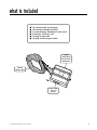
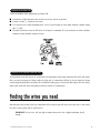
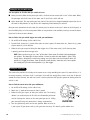
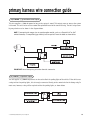
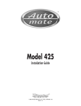
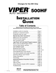
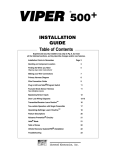
®
Model 725T
Installation Guide
© 2002 Directed Electronics, Inc. Vista, CA N725T 4-02
table of contents
what is included . . . . . . . . . . . . . . . . . . . . . 3
installation points to remember . . . . . . . . . . 4
deciding on component locations . . . . . . . . . 4
locations for the siren . . . . . . . . . . . . . . . . 4
locations for the control module . . . . . . . . . 5
on-board stinger doubleguard shock sensor . . 6
locations for valet/program switch . . . . . . . . 6
locations for the status LED . . . . . . . . . . . . 6
locations for the optional starter kill relay. . . 7
finding the wires you need . . . . . . . . . . . . . . 7
obtaining constant 12V . . . . . . . . . . . . . . . 7
finding the 12V switched ignition wire . . . . . 8
finding a (+) parking light wire . . . . . . . . . . 8
finding the door pin switch circuit . . . . . . . . 9
finding the starter wire . . . . . . . . . . . . . . 10
harness 2, (-) door lock outputs . . . . . . . . . 17
type A door locks . . . . . . . . . . . . . . . . . . 18
type B door locks . . . . . . . . . . . . . . . . . . 19
type C door locks . . . . . . . . . . . . . . . . . . 20
type D door locks . . . . . . . . . . . . . . . . . . 21
type E door locks . . . . . . . . . . . . . . . . . . 22
type F door locks . . . . . . . . . . . . . . . . . . 23
type G door locks . . . . . . . . . . . . . . . . . . 24
type H door locks . . . . . . . . . . . . . . . . . . 25
transmitter/receiver learn routine™ . . . . . . . 26
two-vehicle operation with single transmitter 27
operating settings learn routine™ . . . . . . . . 28
feature menu . . . . . . . . . . . . . . . . . . . . . . 29
feature descriptions . . . . . . . . . . . . . . . . . 30
making your wiring connections . . . . . . . . . 10
nuisance prevention circuitry (NPC™) . . . . . . 31
primary harness (H1), 12-pin connector . . . . 11
valet mode . . . . . . . . . . . . . . . . . . . . . . . . 32
primary harness wire connection guide . . . . . 12
table of zones . . . . . . . . . . . . . . . . . . . . . . 32
on-board stinger doubleguard shock sensor . . 16
troubleshooting . . . . . . . . . . . . . . . . . . . . 33
bypassing sensor inputs . . . . . . . . . . . . . . . 16
Bitwriter™, Code Hopping™, DEI®, Doubleguard®, ESP™, FailSafe®, Ghost Switch™, Learn
Routine™, Nite-Lite®, Nuisance Prevention Circuitry®, NPC®, Revenger®, Silent Mode™, Soft Chirp®,
Stinger®, Valet®, Vehicle Recovery System®, VRS®, and Warn Away® are all Trademarks or Registered
Trademarks of Directed Electronics, Inc.
2
© 2002 Directed Electronics, Inc. Vista, CA
what is included
■
■
■
■
■
■
The control module (see diagram)
Two remote transmitters P/N 491T
A on-board Stinger® Doubleguard® shock sensor
A Revenger® Soft Chirp® siren
The plug-in status LED
The plug-in Valet®/Program switch
Stinger
Doubleguard
Shock Sensor
Adjustment
Primary
Harness (H1)
3-pin, 2-wire
door lock
harness
© 2002 Directed Electronics, Inc. Vista, CA
3
installation points to remember
Do not disconnect the battery if the vehicle has an anti-theft-coded radio. If equipped with an air bag, avoid
disconnecting the battery if possible. Many airbag systems will display a diagnostic code through their warning
lights after they lose power. Disconnecting the battery requires this code to be erased, which can require a trip
to the dealer.
Before beginning the installation:
■ Check with the customer on status LED location.
■ Remove the domelight fuse. This prevents accidentally draining the battery.
■ Roll down a window to avoid being locked out of the car.
After the installation:
■ Test all functions. The “Using Your System” section of the Owner's Guide is very helpful when testing.
■ When testing, don’t forget that this system is equipped with Nuisance Prevention Circuitry™(NPC™). NPC can
bypass trigger zones, making them appear to stop working. See the Nuisance Prevention Circuitry section.
deciding on component locations
locations for the siren
Some things to remember about mounting the siren:
■ Keep it away from heat sources, such as radiators, exhaust manifolds, turbochargers, and heat shields.
■ Mount it where a thief cannot easily disconnect it, whether the hood is open or shut. Both the siren and its
wires should be difficult to find. This usually involves disguising the wire to look like a factory harness.
■ We recommend against grounding the siren to its mounting screws. Instead, we recommend running both the
red and black wires into the passenger compartment and grounding to one common point for all devices.
After all, both wires are the same length and come already bonded together. Whenever possible, conceal your
wires in the factory harnesses or in the same style loom as the factory.
■ When possible, place the siren on the same side of the vehicle as the control module, where its wires will
reach the control module’s wires without extending them. Always run the wires through the center of a
grommet, never through bare metal!
■ Point the siren down so water does not collect in it.
4
© 2002 Directed Electronics, Inc. Vista, CA
Some good siren locations:
locations for the control module
Some things to remember about where to mount the control module:
■ Never put the control module in the engine compartment!
■ The first step in hot-wiring a vehicle is removing the driver's side under-dash panel to access the starter and
ignition wires. If the control module is placed just behind the driver's side dash it can easily be disconnected.
■ When mounting the control module, try to find a secure location that will not require you to extend the harnesses’ wires (they are 1.5 meters long). Keep it away from the heater core (or any other heat sources) and
any obvious leaks.
■ The higher the control module is in the vehicle, the better the transmitter range will be. If you put the control
module under a seat or inside a metal dashboard, range will suffer, and you may wish to add a DEI® 542T
Range Extending Antenna (available separately).
Some good control module locations:
© 2002 Directed Electronics, Inc. Vista, CA
5
on-board stinger doubleguard shock sensor
How the control module is mounted is the most important factor in determining the performance of the on-board
shock sensor. We recommend two methods for mounting the control module:
■ Using double-sided tape or hook-and-loop fastener to mount to a trim panel or an air duct, or
■ Wire-tying to a wire harness.
If mounting the control module where it cannot be easily accessed for adjustment, hook-and-loop fastening tape
(such as Velcro) is recommended for ease of removal for future adjustments.
NOTE: In many vehicles, screwing the control module to metal will result in poor sensitivity, especially at the rear of the vehicle.
locations for valet/program switch
IMPORTANT! When the vehicle is delivered, please show the user where this switch is located and
how to disarm the system with it.
Ensure that the location you pick for the switch has sufficient clearance to the rear. The switch should be well
hidden. It should be placed so passengers or stored items (such as items stored in a glove box or center console)
cannot accidentally hit it. The switch fits into a 9/32-inch hole.
This system features Remote Valet®. The user can enter and exit Valet® Mode without having to reach for the
Valet®/Program switch. Directed introduced this feature so that Valet/Program switch location was less critical in
day-to-day use. As long as it can be reached to disarm without a transmitter, easy access to this switch is not
vital.
6
© 2002 Directed Electronics, Inc. Vista, CA
locations for the status LED
Things to remember when positioning the Status LED:
■ It should be visible from both sides and the rear of the vehicle, if possible.
■ It needs at least 1/2" clearance to the rear.
■ It is easiest to use a small removable panel, such as a switch blank or a dash bezel. Remove it before drilling
your 9/32" hole.
■ Use quick-disconnects near the LED wires if the panel is removable. This lets mechanics or other installers
remove the panel without cutting the wires.
locations for the optional starter kill relay
If the optional starter kill relay or its connections are immediately visible upon removal of the under-dash panel,
they can easily be bypassed. Always make the relay and its connections difficult to discern from the factory
wiring! Exposed yellow butt connectors do not look like factory parts, and will not fool anyone! For this reason,
routing the starter kill wires away from the steering column is recommended.
finding the wires you need
Now that you have decided where each component will be located, you will need to find the wires in the vehicle
that the security system will be connected to.
IMPORTANT! Do not use a 12V test light to locate these wires! Use a digital multimeter for all
testing.
© 2002 Directed Electronics, Inc. Vista, CA
7
obtaining constant 12V
We recommend two possible sources for 12V constant: the (+) terminal of the battery, or the constant supply to
the ignition switch. Always install a fuse within 12 inches of this connection. If the fuse also will be powering
other circuits, such as door locks, a power window module, a Nite-Lite® headlight control system, etc., fuse
accordingly.
IMPORTANT! Do not remove the fuse holder on the red wire. It ensures that the control module has its
own fuse, of the proper value, regardless of how many accessories are added to the main power feed.
finding the 12V switched ignition wire
The ignition wire is powered when the key is in the run or start position. This is because the ignition wire powers
the ignition system (spark plugs, coil) as well as the fuel delivery system (fuel pump, fuel injection computer).
Accessory wires, on the other hand, lose power when the key is in the start position to make more current available to the starter motor.
How to find (+)12V ignition with your multimeter:
1. Set to DCV or DC voltage (12V or 20V is fine).
2. Attach the (-) probe of the meter to chassis ground.
3. Probe the wire you suspect of being the ignition wire. The steering
column harness or ignition switch harness is an excellent place to
find this wire.
4. Turn the ignition key switch to the run position. If your meter reads
(+)12V, go to the next step. If it doesn’t, probe another wire.
5. Now turn the key to the start position. The meter display should stay steady, not dropping by more than a
few tenths of a volt. If it drops close to or all the way to zero, go back to Step 3. If it stays steady at (+)12V,
you have found an ignition wire.
8
© 2002 Directed Electronics, Inc. Vista, CA
finding a (+) parking light wire
Most vehicles use a (+) parking light circuit. In these vehicles, an optional 8617 relay is required to interface
with the light flash feature. The (+) parking light wire is often found near the switch. Many cars have the switch
built into the turn signal lever, and in these cars the parking light wire can be found in the steering column. The
same wire is often available in the kick panel or running board.
NOTE: Many Toyotas, as well as many other Asian vehicles, send a (-) signal from the switch to a
relay. The relay then sends (+)12V to the bulbs. Whenever you have difficulty finding a (+) parking
light wire near the switch, simply test the wires at any switch or control panel which is lit by the
instrument panel lighting. Remember, you need a (+) parking light wire that does not vary with
the dimmer setting.
How to find a (+) parking light flash wire with your multimeter:
1. Set to DCV or DC voltage (12V or 20V is fine).
2. Attach the (-) probe of the meter to chassis ground.
3. Probe the wire you suspect of being the parking light wire. Usually, the area near the headlight/parking light
switch is an excellent area to start, as is the kick panel.
4. Turn on the parking lights. If your meter shows (+)12V, turn off the parking lights and make sure it goes back
to zero.
5. If it does return to zero, turn the parking lights back on and, using the dash light dimmer control, turn the
brightness of the dash lights up and down. If the meter changes more than a volt when using the dimmer,
look for another wire. If it stays relatively close to (+)12V, you have found your parking light wire.
NOTE: Vehicles that use a (-) signal from the switch to the factory relay may be interfaced directly.
These vehicles do not require an optional relay.
© 2002 Directed Electronics, Inc. Vista, CA
9
finding the door pin switch circuit
The best places to find the door pin switch wire are:
■ At the pin switch: When testing at the pin switch, check the wire to ensure that it “sees” all the doors. Often,
the passenger switch will cover all the doors even if the driver’s switch will not.
■ At the dome light: This may not be your best choice if the vehicle has delayed domelight supervision, but it
will work in many Hondas, or any vehicle with completely diode-isolated pin switches.
Once you have determined the wire color, the easiest place to connect to the wire is often at the kick panel, at
the windshield pillar, or in the running board. When an easy location is not available, running a wire to the domelight itself is often the best solution.
How to find a door pin switch trigger wire with your multimeter:
1. Set to DCV or DC voltage (12V or 20V is fine).
2. In most Fords, fasten the (-) probe of the meter to chassis ground. In most other cars, fasten the (+) probe
of your meter to (+)12V constant.
3. Probe the wire you suspect of being the door trigger wire. If the meter reads (+)12V when any door
is opened, you have found a trigger wire.
NOTE: Make sure the wire you use “sees” all the doors! Some newer GM vehicles lack standard-type
pin switches. The dome light in these vehicles is turned on when the door handle is lifted. These
usually have a blue/white or white wire coming out of the door into the kick panel which will
provide a (-) trigger for all doors. Some GM vehicles (some Cavaliers, Grand Ams, etc.) have a yellow
wire coming out of the door which provides a (+) door trigger.
finding the starter wire
The starter wire provides 12V directly to the starter or to a relay controlling the starter. In some vehicles, it is
necessary to power a cold start circuit. A cold start circuit will test exactly like a starter circuit, but it does not
control the starter. Instead, the cold start circuit is used to prime the fuel injection system for starting when the
vehicle is cold.
How to find the starter wire with your multimeter:
1. Set to DCV or DC voltage (12V or 20V is fine).
2. Attach the (-) probe of the meter to chassis ground.
3. Probe the wire you suspect of being the starter wire. The steering
column is an excellent place to find this wire. Remember you do not
need to interrupt the starter at the same point you test it. Hiding
your starter kill relay and connections is always recommended.
4. Turn the ignition key switch to the start position. Make sure the car
is not in gear! If your meter reads (+)12V, go to the next step. If it doesn’t, probe another wire.
10
© 2002 Directed Electronics, Inc. Vista, CA
5. Cut the wire you suspect of being the starter wire.
6. Attempt to start the car. If the starter engages, reconnect it and go back to Step 3. If the starter does not
turn over, you have located the correct wire.
making your wiring connections
Before making your connections, plan how your wires will be routed through the vehicle. For instance, the yellow
ignition input, the red 12V constant input, and the orange ground-when-armed output (for the optional starter
kill relay) will often be routed together to the ignition switch harness. In order to keep the wiring neat and make
it harder to find, you may wish to wrap these wires together in electrical tape or conceal them in tubing similar
to what the manufacturer used.
There are two acceptable ways of making a wire connection - solder connections and crimp connectors. When
properly performed, either type of connection is reliable and trouble-free. Regardless of whether you solder your
connections or you use mechanical-type crimp-on connections, ensure that all connections are mechanically
sound and that they are insulated.
Cheap electrical tape, especially when poorly applied, is not a reliable insulator. It often falls off in hot weather.
Use good-quality electrical tape or heat shrink.
■ Never twist-and-tape the wires together without soldering.
■ Never use “fuse taps”, as they can damage fuse box terminals.
If you use tapping connectors such as 3M T-Taps (not to be confused with Scotch-Locks), avoid using them in
higher-current applications (constant 12V, ground, etc.). Some tapping connectors are inferior in quality and
should be avoided.
© 2002 Directed Electronics, Inc. Vista, CA
11
primary harness (H1), 12-pin connector
H1/1
H1/2
H1/3
H1/4
H1/5
H1/6
H1/7
H1/8
12
______
______
______
______
______
______
______
______
ORANGE
WHITE
WHITE/BLUE
BLACK/WHITE
GREEN
BLUE
(-) 500 mA ARMED OUTPUT
(-) 200 mA LIGHT FLASH OUTPUT
(-) 2V LED OUTPUT
(-) VALET/PROGRAM BUTTON INPUT
(-) DOOR TRIGGER INPUT, ZONE 3
(-) INSTANT TRIGGER INPUT, ZONE 1
VIOLET
(+) DOOR TRIGGER INPUT, ZONE 3
BLACK
(-) CHASSIS GROUND INPUT
H1/9 ______
YELLOW
(+) SWITCHED IGNITION INPUT, ZONE 5
H1/10 ______
BROWN
(+) SIREN OUTPUT
H1/11 ______
RED
H1/12 ______
RED/WHITE
(+) CONSTANT POWER INPUT
(-) 200 mA CHANNEL 2 VALIDITY OUTPUT
© 2002 Directed Electronics, Inc. Vista, CA
primary harness wire connection guide
H1/1 ORANGE (-) ground-when-armed output
This wire supplies a (-)500 mA ground as long as the system is armed. This output ceases as soon as the system
is disarmed. This wire can be used to control the optional Directed 8618 starter kill relay. The 8617 relay assembly may also be used as shown in the diagram below.
NOTE: If connecting the orange wire to control another module, such as a Directed 529T or 530T
window controller, a 1 amp diode (type 1N4004) will be required. Insert the diode as shown below.
IMPORTANT! Never interrupt any wire other than the starter wire.
H1/2 WHITE (-) light flash output
The unit supplies a (-)200mA output that can be used to flash the parking lights of the vehicle. If the vehicle uses
a relay to drive the parking lights, this wire may be connected directly to the control wire for the factory relay. In
most cases, however, a relay will be required to drive the parking lights, as shown below.
© 2002 Directed Electronics, Inc. Vista, CA
13
H1/3 WHITE/BLUE (-) 2V LED output
Connect this wire to the blue wire on the status LED. Then connect the red wire of the status LED to (+) 12V
constant fused.
H1/4 BLACK/WHITE valet/program switch input
Connect to the gray wire on the Valet/program switch. The black wire on the Valet/program switch should be
connected to chassis ground.
H1/5 GREEN (-) door trigger or H1/7 VIOLET (+) door trigger input
If the door switch wire you found is (-) when the door is open, connect the green wire to it. If the door switch
wire you found is (+) when the door is open, use the violet wire instead.
IMPORTANT! Test to make sure this wire "sees" all doors!
H1/6 BLUE (-) instant trigger input
This input will respond to a (-) input with an instant trigger. It is ideal for hood and trunk pins and will report
on Zone 1. If connecting several inputs to this wire, they should be diode isolated as shown.
14
© 2002 Directed Electronics, Inc. Vista, CA
H1/7 VIOLET (see H1/5 GREEN)
H1/8 BLACK (-) chassis ground connection
Connect this wire to a clean, paint-free sheet metal location (driver kick panel) using a factory bolt that DOES
NOT have any vehicle component grounds attached to it. A screw should only be used when in conjunction with
a two-sided lock washer. Under dash brackets and door sheet metal are not acceptable ground points. It is recommended that all security components be grounded at the same location.
H1/9 YELLOW (+) ignition input
Connect this wire to an ignition wire. This wire must show (+) 12V with the key in the run position and during
cranking.
IMPORTANT! Make sure that this wire cannot be shorted to the chassis at any point.
© 2002 Directed Electronics, Inc. Vista, CA
15
H1/10 BROWN (+) siren output
Connect this to the red wire of the Revenger™ siren. Connect the black wire of the siren to (-) chassis ground,
preferably at the same point you grounded the control module’s H1/8 BLACK wire.
H1/11 RED (+)12V constant power input
Before connecting this wire, remove the supplied fuse. Connect to the battery positive terminal or the constant 12V supply to the ignition switch as described in the Finding the Wires You Need section of this guide.
NOTE: Always use a fuse within 12 inches of the point you obtain (+)12V. Do not use the 10A fuse
in the harness for this purpose. This fuse protects the module itself.
H1/12 RED/WHITE channel 2, 200mA (-) output
When the system receives the code controlling Channel 2 for longer than 1.5 seconds, the red/white wire will
supply an output as long as the transmission continues. This is often used to operate a trunk/hatch release or
other relay-driven function.
IMPORTANT! Never use this wire to drive anything but a relay or a low-current input! The transistorized output can only supply 200 mA of current. Connecting directly to a solenoid, motor, or other
high-current device will cause it to fail.
16
© 2002 Directed Electronics, Inc. Vista, CA
on-board stinger doubleguard shock sensor
There is a dual-stage shock sensor inside the control unit. Adjustments are made via the rotary control as indicated in the diagram. Since the shock sensor does not work well when mounted firmly to metal, we do not
recommend screwing down the control module. The full trigger of the on-board shock sensor reports Zone 2. (See
Table of Zones section of this guide.)
NOTE: When adjusting the sensor, it must be in the same mounting location that it will be after
the installation is completed. Adjusting the sensor and then relocating the module requires readjustment.
bypassing sensor inputs
There are times when you need to temporarily bypass all sensor inputs to the unit, such as when remote starting the vehicle. Anytime an auxiliary channel output is used, all inputs are bypassed for five seconds. During the
five second bypass period, ground can be supplied to the H1/6 Blue wire without triggering the unit. When the
five second bypass period ends, if the unit sees ground on the H1/6 Blue wire, all trigger inputs except the door
trigger input will remain bypassed until five seconds after ground is removed from the BLUE wire. This can be
done using the status output of a Directed Electronics remote engine starting unit as shown in the following
diagram:
© 2002 Directed Electronics, Inc. Vista, CA
17
harness 2, (-) door lock outputs
H2/A
H2/B
H2/C
______
______
______
GREEN
(-) LOCK
EMPTY
UNLESS USING 451M
BLUE
(-) UNLOCK
These wires provide (-)200mA pulses that are used to control electric door locks. Most common interfaces are
described in this section.
IMPORTANT! If you mistake a Type C direct-wired system for a Type A positive-pulse system, the
module will be damaged!
type A: (+) 12V pulses from the switch to the factory relays
The system can control Type A door locks, with the addition of a 451M Door Lock Relay module or two relays.
The switch will have three wires on it, and one will test (+)12V constantly. The others will alternately pulse
(+)12V when the switch is pressed to the lock or unlock position.
If you cannot get to the switch, and you find a set of wires that pulses (+)12V alternately on lock and unlock,
you must take care to ensure that it is not a Type C direct-wire system.
Here is a test: Cut the wire which pulses (+)12V on lock, and then operate the switch to unlock.
■ If all doors unlock, the vehicle uses type A system.
■ If you lose all door lock operation in both directions, you are operating the master switch in a Type C system.
■ If you lose all door lock operation of one or more, but not all motors stop operating, and other doors still
work, you have cut a wire leading directly to one or more motors. You must instead find the actual wires
leading to the switch.
Many domestically-made GM vehicles use Type A locks. However, many more GM vehicles are Type C than in previous years. The full-size pickups (1989-up), many of the S10 Blazers, the Corvette, '95 Cavalier/Sunfire 1993
and newer, Camaro/Firebird all use Type C door locks, and cannot be controlled without a 451M! Almost all domestically-built Fords are Type C. Ford builds almost no Type A systems. Chrysler builds both Type A and Type C, so
use care.
IMPORTANT! Remember that these wires' functions reverse between Type A and Type B!
18
© 2002 Directed Electronics, Inc. Vista, CA
type B: (-) pulses from the switch to the factory relays
This door lock system is common in many Toyotas, Nissans, Hondas, and Saturns, as well as Fords with the keyless
entry system (some other Fords also use Type B).
The switch will have three wires on it, and one wire will test ground all the time. One wire will pulse (-) when
the switch locks the doors, and the other wire will pulse (-) when the switch unlocks the doors. This type of
system is difficult to mistake for any other type.
IMPORTANT! Remember that these wires' functions reverse between Type A and Type B!
© 2002 Directed Electronics, Inc. Vista, CA
19
type C: reversing polarity
Interfacing with a reversing polarity system requires either two relays or one Directed 451M (not included). It is
critical to identify the proper wires and locate the master switch to interface properly. Locate wires that show
voltage on lock and unlock. Cut one of the suspect wires and check operation of the locks from both switches.
If one switch loses operation in both directions and the other switch operates in one direction only, you have
located one of the target wires. The switch that lost all operation is the master switch. If one switch works both
directions and the other switch works only one direction, you have a Type A system. If both switches still
operate, but one or more doors has stopped responding entirely, you have cut a motor lead. Reconnect it and
continue to test for another wire. Once both wires have been located and the master switch identified, cut both
wires and interface as shown below.
IMPORTANT! If these are not connected properly, you will send (+) 12 Volts directly to (-) ground,
possibly damaging the alarm or the factory switch.
20
© 2002 Directed Electronics, Inc. Vista, CA
type D: after-market actuators
In order for this system to control one or more after-market actuators, a Directed 451M or two relays (optional)
are needed. Vehicles without factory power door locks require the installation of one actuator per door. This
requires mounting the door lock actuator inside the door. Other vehicles may only require one actuator installed
in the driver's door if all door locks are operated when the driver's lock is used. This type of installation is required
to operate factory lock systems in Volvo (except 850), SAAB, and most Mazda, Isuzu and Subaru models.
The fuse used on 12V inputs should be 7.5A per motor installed in the vehicle.
IMPORTANT! Do not connect the outputs of the alarm directly to the actuator!
© 2002 Directed Electronics, Inc. Vista, CA
21
type E: mercedes-benz and audi (1985 & newer)
Type E door locks are controlled by an electrically activated vacuum pump. Some Mercedes and Audis use a Type
D system. Test by locking doors from the passenger key cylinder. If all the doors lock, the vehicle's door lock
system can be controlled with just two relays (optional). The control wire can be found in either kick panel and
will show (+)12V when doors are unlocked and (-) ground when doors are locked.
To interface see diagram below. The system must be programmed for 3.5 second door lock pulses. (See OperationSettings Learn Routine™ section of this guide.)
22
© 2002 Directed Electronics, Inc. Vista, CA
type F: one-wire system
This type of door lock system usually requires a negative pulse to unlock, and cutting the wire to lock the door.
In some vehicles, these are reversed. Type F door lock systems are found in late-model Nissan Sentras, some
Nissan 240SX, and Nissan 300ZX 1992-up. This type of system is also found in some Mazda MPV's and some
Mitsubishi's.
One relay (optional) is used to interface to this type of system as follows:
© 2002 Directed Electronics, Inc. Vista, CA
23
type G: positive multiplex
This system is most commonly found in Ford, Mazda, Chrysler and GM vehicles. The door lock switch or door key
cylinder may contain either one or two resistors. When interfacing with this type of door lock system, two relays
or a DEI 451M must be used. (See diagram below.)
single-resistor type
If one resistor is used in the door lock switch/key cylinder, the wire will pulse (+)12V in one direction and less
than (+)12V when operated in the opposite direction.
two-resistor type
If two resistors are used in the factory door lock switch/key cylinder, the switch/key cylinder will read less than
(+)12V in both directions.
determining the proper resistor values
To determine the resistor values, the door lock switch/key cylinder must be isolated from the factory door lock
system. For all testing, use a calibrated digital multimeter that is set to ohms.
1. Cut the output wire from the door lock switch/key cylinder in half.
2. Test with the meter from the switch side of the cut door lock switch/key cylinder wire to a reliable constant
(+)12V source. Some good constant (+)12V references are the power input source to the door lock switch/key
cylinder, the ignition switch power wire, or the (+) terminal of the battery.
3. Operate the door lock switch/key cylinder in both directions to determine the resistor values. If the multimeter displays zero resistance in one direction, no resistor is needed for that direction.
4. Once the resistor value(s) is determined, refer to the wiring diagram for proper wiring.
24
© 2002 Directed Electronics, Inc. Vista, CA
type H: negative multiplex
The system is most commonly found in Ford, Mazda, Chrysler and GM vehicles. The door lock switch or door key
cylinder may contain either one or two resistors. When interfacing with this type of door lock system, two relays
or a DEI 451M must be used. (See diagram below.)
single-resistor type
If one resistor is used in the door lock switch/key cylinder, the wire will pulse ground in one direction and resistance to ground when operated in the opposite direction.
two-resistor type
If two resistors are used in the factory door lock switch/key cylinder, the door lock switch/key cylinder will read
resistance to ground in both directions.
determining the proper resistor values
To determine the resistor values, the door lock switch/key cylinder must be isolated from the factory door lock
system. For all testing, use a calibrated digital multimeter that is set to ohms.
1. Cut the output wire from the door lock switch/key cylinder in half.
2. Test with the meter from the switch side of the cut door lock switch/key cylinder wire to a reliable ground
source. Some good ground references are the ground input source to the door lock switch/key cylinder or the
battery ground.
3. Operate the door lock switch/key cylinder in both directions to determine the resistor values. If the multimeter displays zero resistance in one direction, no resistor is needed for that direction.
4. Once the resistor value(s) is determined, refer to the wiring diagram for proper wiring.
© 2002 Directed Electronics, Inc. Vista, CA
25
™
transmitter/receiver learn routine
The system comes with two transmitters that have been taught to the receiver. The receiver can store up to four
different transmitter codes in memory. Use the following learn routine to add transmitters to the system or to
change button assignments if desired.
The Valet®/Program switch is used for programming. There is a basic sequence to remember whenever programming this unit: Door, Key, Choose, Transmit and Release.
1.
Open a door. (The GREEN wire, H1/5, or the VIOLET, H1/7 must be connected.)
2.
Key. Turn the ignition on. (The H1/9 YELLOW switched ignition input must be connected.)
3.
Select the receiver channel. Press and release the Valet®/Program switch the number of
times necessary to access the desired channel. Once you have selected a channel, press
and hold the Valet®/Program switch once more. The siren will chirp the number of times
corresponding to the channel that has been accessed.
CHANNEL NUMBER
4.
FUNCTION
1
Arm/Disarm/Panic
2
Channel Two Output (Silent Mode/Remote Valet)
3
No function
Press the transmitter button. While still holding the Valet®/Program switch, press the
button from the transmitter that you wish to assign to that channel. The unit will chirp
indicating successful programming. It is not possible to teach a transmitter button to the
system more than once.
5.
Release. Once the code is learned, the Valet®/Program switch can be released.
You can advance from one channel to another by releasing the Valet®/Program switch and tapping it to advance
channels and then holding it. For example, if you want to program Channel Two after programming Channel One,
release the Valet®/Program switch. Press it once and release it to advance to Channel Two. Then press it once
more and hold it. The siren will chirp two times to confirm it is ready to receive the code from the transmitter.
26
© 2002 Directed Electronics, Inc. Vista, CA
Learn Routine™ will be exited if:
■ Ignition is turned off.
■ Door is closed.
■ Valet®/Program button is pressed too many times.
■ More than 15 seconds elapses between steps.
One long chirp indicates that Learn Routine™ has been exited.
two-vehicle operation with single transmitter
Two-vehicle operation is possible with the transmitters that come with the system; however, you will not be able
to use all the auxiliary channels of the system (or all the auxiliary channels of the other system), unless using
an optional compatible 4-button transmitter.
Here's what to do:
1. Using the Learn Routine, program Button I into the security system of Vehicle 1 as the arm/disarm button.
Do this with all four remotes.
2. Now do the same for the Vehicle 2 security system, except this time program Button II of all four remotes
as the arm/disarm button.
If using optional four-button remotes, all auxiliary channels are available on both vehicles. Before programming,
make a list of all channels on each vehicle, and decide which button(s) should control which channel.
For example, if you wanted the top two buttons to control Vehicle 1 and the bottom two buttons to control
Vehicle 2, here is how each system would need to be programmed:
VEHICLE 1
Button I
Arm/Disarm
Button II
Channel Two Output (Silent Mode/Remote Valet)
Buttons I and II
No function
VEHICLE 2
Button III
Arm/Disarm
Button IV
Channel Two Output (Silent Mode/Remote Valet)
Buttons III and IV
No function
© 2002 Directed Electronics, Inc. Vista, CA
27
™
operating settings learn routine
Many of the operating settings of this unit are programmable. They can be changed whenever necessary through
a computer-based System Features Learn Routine™. The Valet®/Program push-button switch is used together with
a programmed transmitter to change the settings.
To program the System Features Learn Routine™:
1.
Open a door. (The GREEN wire, H1/5, or the VIOLET, H1/7 must be connected.)
2.
Ignition. Turn the ignition on, then back off. (The H1/9 YELLOW switched ignition input
must be connected.)
3.
Select a Feature. Within 15 seconds press and release the Valet®/Program switch the
number of times corresponding to the feature number you wish to change (see Feature
Menu). The one-chirp settings on the Feature Menu chart are the factory default settings,
except where indicated by bold text. Once the Valet/Program switch has been pressed and
released the desired number of times, press it once more and hold it. After one second, the
siren will chirp to indicate which feature you have accessed. For example, three chirps
would indicate access to Feature 3 (Ignition Controlled Door Locks).
4.
Program the Feature. While holding the Valet®/Program switch, you can toggle between
the one and two-chirp feature settings by pressing the arm/disarm button on the remote
transmitter. Press the arm/disarm button on the transmitter once to select the one chirp
or default setting. Pressing the arm/disarm button again will select the two chirp setting.
5.
Release. Release the Valet®/Program switch.
For example, to program Feature 1 (Arming Mode) from active to passive, press and release the Valet/Program
switch once, and then press and hold it. The siren will chirp once, indicating that the setting can now be
changed. While holding the Valet/Program switch, press the arm/disarm button on the transmitter. The siren will
chirp twice to indicate that passive arming has been programmed. If this is the desired setting, release the
28
© 2002 Directed Electronics, Inc. Vista, CA
Valet/Program switch. If this is not the desired setting, continue to hold the Valet/Program switch and press the
arm/disarm button on the transmitter again. The siren will chirp once indicating that active arming has been
programmed. Once the desired setting has been selected, release the Valet/Program switch.
You can advance from feature to feature by pressing and releasing the Valet/Program switch the number of times
necessary to advance from the feature you just programmed to the feature you wish to access. If you just programmed Feature 2 (Arm/Disarm Chirps) to off and you next want to program Feature 4 (Passive Locks), release
the Valet/Program switch, press and release it twice to advance from Feature 2 to Feature 4. Then press it once
more and hold it. The unit will chirp four times to confirm that you have accessed Feature 4.
To exit the learn routine, do one of the following:
1. Close the open door.
2. Turn the ignition on.
3. No activity for longer than 15 seconds.
4. Press the Valet®/Program switch too many times.
The siren will emit a long chirp when the Learn Routine has been exited.
feature menu
Features in bold text have been programmed to the two chirp setting at the factory.
FEATURE NUMBER
ONE-CHIRP SETTING (DEFAULT)
TWO-CHIRP SETTING
1
Active arming
Passive arming
2
Arm/disarm chirps on
Arm/disarm chirps off
3
Ignition-controlled door locks
Standard door locks
4
Active locking only
Passive locking
5
Panic with ignition on
No panic with ignition on
6
0.8 second door lock pulses
3.5 second door lock pulses
7
Forced passive arming on
Forced passive arming off
8
Automatic engine disable on
Automatic engine disable off
9
Double pulse unlock off
Double pulse unlock on
10
Code Hopping on
Code Hopping off
11
Siren
Horn honk
© 2002 Directed Electronics, Inc. Vista, CA
29
feature descriptions
The programmable features of this system are described below.
1 ACTIVE/PASSIVE ARMING: When active arming is selected, the system will only arm when the transmitter is
used. When set to passive, the system will arm automatically 30 seconds after the last door is closed. Passive
arming is indicated by the rapid flashing of the LED when the last protected entry point is closed.
2 CHIRPS ON/OFF: This feature controls the chirps that confirm the arming and disarming of the system.
3 IGNITION CONTROLLED DOOR LOCKS ON/OFF: When turned on, the doors will lock three seconds after the
ignition is turned on and unlock when the ignition is turned off. The doors will not lock if the ignition is turned
on with the door open.
4 ACTIVE/PASSIVE LOCKING: If passive arming is selected in Feature 1, then the system can be programmed to
either lock the doors when passive arming occurs, or only lock the doors when the system is armed via the transmitter. Active locking means the system will not lock the doors when it passively arms. Passive locking means
that the system will lock the doors when it passively arms.
5 PANIC WITH IGNITION ON: This feature controls whether or not the panic mode is available with the ignition
on. In some states, there are laws prohibiting a siren sounding in a moving vehicle. This feature makes the system
compliant with these regulations.
6 DOOR LOCK PULSE DURATlON: Some European vehicles, such as Mercedes-Benz and Audi, require longer lock
and unlock pulses to operate the vacuum pump. Programming the system to provide 3.5 second pulses will
accommodate the door lock interface in these vehicles. The default setting is 0.8 second door lock pulses. (See
Harness 2 (-) Door Lock Outputs section, "Type E - Mercedes-Benz and Audi -1985 and Newer" diagram.)
7 FORCED PASSIVE ARMING ON/OFF: To use this feature, passive arming must be selected in Feature 1. When
turned on, forced passive arming will ensure that the system will passively arm, even if a zone is left open or
invalid. Forced passive arming occurs one hour after the ignition is turned off.
8 AUTOMATIC ENGINE DISABLE (AED) ON/OFF: AED is a full-time, passive starter disable that works independently of the security system. For AED to be operational, the optional starter kill relay must be installed. When
turned on, the orange, ground-when-armed output (H1/1) will activate 30 seconds after the ignition is turned
off. The LED will flash at half its normal rate when the ignition is turned off to indicate that AED is active and
will interrupt the starter in 30 seconds. AED does not occur in Valet® Mode and can be bypassed using the emergency override procedure. The transmitter can be used to disarm AED, however, the system must be armed and
then disarmed, using the transmitter, in order for AED to be disarmed.
30
© 2002 Directed Electronics, Inc. Vista, CA
9 DOUBLE PULSE UNLOCK OFF/ON: Some vehicles require two pulses on a single wire to unlock the doors. When
the double pulse unlock feature is turned on, the BLUE H2/C wire will supply two negative pulses instead of a
single pulse. At the same time, the GREEN H2/A wire will supply two (+) pulses instead of a single pulse. This
makes is possible to directly interface with double pulse vehicles without any extra parts.
10 CODE HOPPING™ ON/OFF: The system uses a mathematical formula to change its code each time the transmitter and receiver communicate. This makes the group of bits or "word" from the transmitter very long. The
longer the word is, the easier it is to block its transmission to the unit. Disabling the Code Hopping™ feature lets
the receiver ignore the Code Hopping™ part of the transmitted word. As a result, the unit may have better range
with Code Hopping™ off.
11 SIREN/HORN HONK: The system can be programmed to output pulses instead of a continuous output when
the system is triggered. This is useful to honk the factory horn in applications where a siren is undesirable. Remember that the unit is only capable of supplying 1 amp of current. A relay will be required to interface with
most factory horn systems.
™
nuisance prevention circuitry (NPC )
NPC requires that you change the way you test the system as NPC will bypass an input zone for 60 minutes.
If the system “sees” the same zone trigger three times AND the triggers are spaced less than an hour apart, the
system will bypass that input zone for 60 minutes.
If that zone does not attempt to trigger the system during the 60-minute bypass period, the zone’s monitoring
will begin again at the end of the hour. If it does attempt to trigger while bypassed, the 60-minute bypass starts
over again.
Disarming and rearming the system does not reset NPC. The only way to reset NPC is for the 60 minutes to pass,
without a trigger, or for the ignition to be turned on. This allows the system to be repeatedly triggered, disarmed
and rearmed, while still allowing NPC to bypass a faulty zone.
When disarming the system, 5 chirps indicate NPC is activated. The LED will report the zone that has been
bypassed. (See Table of Zones section.)
© 2002 Directed Electronics, Inc. Vista, CA
31
valet mode
to enter or exit valet mode with the valet/program switch
1.
Turn the ignition key on and then off.
2.
At any time during the next 10 seconds, press and release the Valet® switch. Now the Status
LED will light constantly if you have entered Valet® Mode, and will go out if you have exited
Valet® Mode.
to enter or exit valet mode with the transmitter
To enter or exit Valet® Mode with a transmitter:
1. Open any door.
2. Press
on the transmitter (or the arm/disarm button).
3. Press
(or the Channel II button).
4. Press
again. You have now entered or exited Valet Mode (verify by checking the status LED).
table of zones
When using the Diagnostic functions, use the Table of Zones below to see which input has triggered the system.
It is also helpful in deciding which input to use when connecting optional sensors and switches.
ZONE NO.
TRIGGER TYPE
INPUT DESCRIPTION
1
Instant
H1/6 BLUE wire. Connect to optional hood/trunk pins.
2
Multiplexed Input
Second-stage output of Stinger Doubleguard shock sensor.
3
Two stage, progresses from
warning to full alarm
Door switch circuit. H1/5 GREEN or H1/7 VIOLET.
5
Two-stage (similar to doors)
Ignition. YELLOW (H1/9).
NOTE: The Warn Away® response does not report on the LED.
32
© 2002 Directed Electronics, Inc. Vista, CA
troubleshooting
■ Optional starter kill does not work:
Is the correct starter wire being interrupted? If the vehicle starts when the starter kill relay is completely disconnected, the wrong starter wire has been cut and interrupted.
■ Shock sensor doesn't trigger the alarm:
Has the NPC system been triggered? If so, you will hear 5 chirps when disarming. To check this, turn the ignition key on and off to clear the NPC memory, and then retest the shock sensor. For a detailed description of NPC,
refer to the Nuisance Prevention Circuitry section of this guide.
■ Door input does not immediately trigger full alarm. Instead, chirps are heard for the first 3 seconds:
That's how the progressive two-stage door input works! This is system feature. The system has been designed to
provide an instant trigger, so that even if the door is instantly closed, the progression from chirps to constant
siren will continue.
■ Closing the door triggers the system, but opening the door does not:
Have you correctly identified the type of door switch system? This happens often when the wrong door input has
been used. (See Harness 2, (-) Door Lock Outputs section of this guide.)
■ System will not passively arm until it is remotely armed and then disarmed:
Are the door inputs connected? Is the H1/6 blue wire connected to the door trigger wire in the vehicle? Either
the H1/5 green or the H1/7 violet should be used instead. See Primary Harness Wire Connection Guide section.
■ Door input does not respond with the progressive trigger, but with immediate full alarm:
Does the Status LED indicate that the trigger was caused by the impact sensor? The shock sensor, if set to extreme
sensitivity, may be detecting the door unlatching before the door switch sends its signal. Reducing the sensitivity can solve this problem.
■ Door locks operate backwards.
This unit has easily-reversed lock/unlock outputs. (Refer to Harness 2, (-) Door Lock Outputs section of this guide
to see if you have reversed these.)
© 2002 Directed Electronics, Inc. Vista, CA
33