1
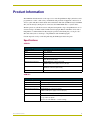
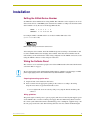
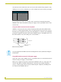
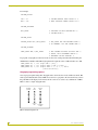
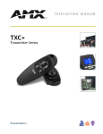
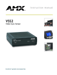
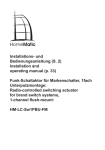
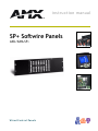
instruction manual
SP+ Softwire Panels
AXU/AXM-SP+
W i r e d C o n t r ol Pa n e l s
AMX Limited Warranty and Disclaimer
AMX Corporation warrants its products to be free of defects in material and workmanship under normal use for
three (3) years from the date of purchase from AMX Corporation, with the following exceptions:
•
Electroluminescent and LCD Control Panels are warranted for three (3) years, except for the display and touch
overlay components that are warranted for a period of one (1) year.
•
Disk drive mechanisms, pan/tilt heads, power supplies, MX Series products, and KC Series products are
warranted for a period of one (1) year.
•
Unless otherwise specified, OEM and custom products are warranted for a period of one (1) year.
•
Software is warranted for a period of ninety (90) days.
•
Batteries and incandescent lamps are not covered under the warranty.
This warranty extends only to products purchased directly from AMX Corporation or an Authorized AMX Dealer.
AMX Corporation is not liable for any damages caused by its products or for the failure of its products to perform.
This includes any lost profits, lost savings, incidental damages, or consequential damages. AMX Corporation is not
liable for any claim made by a third party or by an AMX Dealer for a third party.
This limitation of liability applies whether damages are sought, or a claim is made, under this warranty or as a tort
claim (including negligence and strict product liability), a contract claim, or any other claim. This limitation of
liability cannot be waived or amended by any person. This limitation of liability will be effective even if AMX
Corporation or an authorized representative of AMX Corporation has been advised of the possibility of any such
damages. This limitation of liability, however, will not apply to claims for personal injury.
Some states do not allow a limitation of how long an implied warranty last. Some states do not allow the limitation or
exclusion of incidental or consequential damages for consumer products. In such states, the limitation or exclusion of
the Limited Warranty may not apply. This Limited Warranty gives the owner specific legal rights. The owner may
also have other rights that vary from state to state. The owner is advised to consult applicable state laws for full
determination of rights.
EXCEPT AS EXPRESSLY SET FORTH IN THIS WARRANTY, AMX CORPORATION MAKES NO
OTHER WARRANTIES, EXPRESSED OR IMPLIED, INCLUDING ANY IMPLIED WARRANTIES OF
MERCHANTABILITY OR FITNESS FOR A PARTICULAR PURPOSE. AMX CORPORATION
EXPRESSLY DISCLAIMS ALL WARRANTIES NOT STATED IN THIS LIMITED WARRANTY. ANY
IMPLIED WARRANTIES THAT MAY BE IMPOSED BY LAW ARE LIMITED TO THE TERMS OF THIS
LIMITED WARRANTY.
Table of Contents
Table of Contents
Product Information .................................................................................................1
Specifications .................................................................................................................... 1
AXU-SP+.................................................................................................................................. 1
AXM-SP+ ................................................................................................................................. 1
Front Panel Controls ......................................................................................................... 2
Rear Panel Components ................................................................................................... 2
Installation .................................................................................................................3
Setting the AXlink Device Number .................................................................................... 3
Wiring the Softwire Panel .................................................................................................. 3
Preparing/connecting captive wires ......................................................................................... 3
Wiring guidelines...................................................................................................................... 3
Using the AXlink connector for data and power ....................................................................... 4
Using AXlink with an external 12 VDC power supply............................................................... 4
Mounting the SP+ Panels.................................................................................................. 5
AXU-SP+ and low-profile back box .......................................................................................... 5
AXU-SP+ and UniMount Back Box BB-SP+ (plasterboard)..................................................... 6
AXM-SP+ (rack mount) ............................................................................................................ 8
Programming ..........................................................................................................11
Pushbutton Programming................................................................................................ 11
Pushbutton LEDs ................................................................................................................... 11
Bargraph Programming ................................................................................................... 11
Bargraph programming options.............................................................................................. 12
SP+ Softwire Panels
i
Table of Contents
ii
SP+ Softwire Panels
Product Information
Product Information
The AMX SP+ Softwire Panels are microprocessor-controlled pushbutton display units that can be
programmed to control a wide variety of multimedia and presentation equipment connected to an
Axcess system. The SP+ Softwire Panel Series include the AXU-SP+ (UniMount style) and AXMSP+ (rack-mount style). Each panel is connected to the AMX AXlink bus as a system device.
The SP+ panels are available in custom configured arrangements of up to 64 pushbuttons in an 8 x
8 matrix and up to 24 LEDs in three 8-LED vertical bargraphs. Buttons and LEDs can be used as
independent or combined functions. By using the optional rack-mounting kit, you can place two
SP+ units side by side to obtain up to 128 pushbuttons and six LED bargraphs.
Custom engraved overlays can be designed using the OLDesign Software Program.
Specifications
AXU-SP+
AXU-SP+ Specifications
Dimensions (HWD)
5.28" x 9.65" x 1.07" (134.10 mm x 245.20 mm x 27.20 mm)
Weight
17 oz (0.482 kg)
Power
AXlink or external 11 to 17V DC, 150 mA max.
Enclosure
Non-glare, black metal frame
UniMount Dimensions (HWD)
4.75" x 8.33" x 1.94" (120.7 mm x 211.50 mm x 49.30 mm) UniMount;
metal with black matte finish
Side/Rear panel connectors
• AXlink-AXlink bus connector (Four-pin)
• PWR-12 VDC power supply connector (Two-pin)
Accessories included
• UniMount low-profile Back Box
• AXlink bus connector (4-pin female)
Options
Metal frame with metal wall box, non-glare black
AXM-SP+
AXM-SP+ Specifications
Dimensions (HWD)
5.25" x 19.00" x 1.00" (133.40 mm x 482.60 mm x 25.40 mm)
Weight
17 oz (0.482 kg)
Power
AXlink or external 11 to 17 VDC, 150 mA max.
Enclosure
Non-glare, black metal frame
Side/Rear panel connectors
• AXlink-AXlink bus connector (Four-pin)
• PWR-12 VDC power supply connector (Two-pin)
Accessories included
AXlink bus connector (4-pin female)
Options
• Metal frame with metal wall box, non-glare black
• Logos, multi-color panels
• Rack mount with AXK-SP, 1- or 2-unit mounting
SP+ Softwire Panels
1
Product Information
Front Panel Controls
Softwire Panel pushbuttons can be programmed individually or in any combination as a single
device or as a group. The bargraph LEDs can also be programmed individually or as a group. The
LEDs can be used with any one of the pushbuttons or as an independent display indicator. FIG. 1
illustrates the standard configuration for the SP+ panels. This is the complete pushbutton
arrangement when all 64 pushbuttons and three LED bargraphs are used. By using custom engraved
panels, you can configure the grouping and marking of the pushbuttons to suit your application.
Bargraph 1
Pushbutton 9
Bargraph 2
Bargraph 3
Pushbutton 1
Pushbutton 8
Pushbutton 64
FIG. 1 SP+ push-button and bargraph display arrangement
Rear Panel Components
The SP+ rear panels contain the AXlink bus connector, AXlink LED, and the DIP switch that is
used to set the panel's device number. FIG. 2 shows the back panel component configuration.
PWR
Device
DIP switch
2
1
4
3
2
1
AXlink
AXlink Status LED
FIG. 2 Side and back panel views of the SP+ standard mounting frame
2
!
AXlink (indicator) A green LED indicates activity of the AXlink bus connected to an
Axcess Control System.
!
Device Number Assigned to devices connected to the AXlink bus. Every device on the
bus must have a unique device code. An 8-position DIP switch is used to set the device
number for the AXP-SP+ Softwire Panels.
SP+ Softwire Panels
Installation
Installation
Setting the AXlink Device Number
Set AXU-SP+ device number before wiring AXlink. The AXU-SP+ can be assigned as one of 255
devices in the Axcess or AXCENT system. Set the device number according to the chart below. The
device number is set by the total of all ON (Up) DIP switches.
Switch
1 2 3 4
5
6
7
8
ON Value 1 2 4 8 16 32 64 128
For example, in FIG. 3 the DIP switch is set for device number ON Value of 237
(1 + 4 + 8 + 32 + 64 + 128).
ON
OFF
1 2 3 4 5 6 7 8
FIG. 3 Sample setting for the AXU-SP+ Softwire Panel
After setting the device number, install the AXlink data/power bus wiring as shown. Remove and
reconnect AXlink terminal after changing device number. This enters the new number into the
unit's memory. For more information on the wiring configuration of the AXlink connection, see the
Using the AXlink connector for data and power subsection.
Wiring the Softwire Panel
The connectors are located in the top-right corner of the UniMount and rack-mount Softwire Panels
as shown in FIG. 2 on page 2.
Do not connect power to the Softwire Panel until the wiring is complete. If you are using a 12 VDC
power supply, apply power to the Softwire Panel only after installation is complete.
Preparing/connecting captive wires
1. Strip 0.25 inch of wire insulation off all wires.
2. Insert each wire into the appropriate opening on the connector according to the wiring
diagrams and connector types described in this section.
!
Do not tighten the screws excessively; doing so may strip the threads and damage the
connector.
Wiring guidelines
The panels require 12 VDC power to operate properly. The Axcess Control System supplies power
via the AXlink cable or external 12 VDC power supply. The max-imum wiring distance between
the control system and Softwire Panel is determined by power consumption, supplied voltage, and
the wire gauge used for the cable. The following table lists wire sizes and the maximum lengths
SP+ Softwire Panels
3
Installation
allowable between the Softwire Panel and control system. The maximum wiring lengths for using
AXlink power are based on a minimum of 13.5 volts available at the control system's power supply.
Wiring Guidelines
Wire size Maximum wiring length
18 AWG
782.47 feet (238497.63. mm)
20 AWG
495.05 feet (150891.74 mm)
22 AWG
308.64 feet (94073.78 mm)
24 AWG
194.55 feet (59299.03 mm)
If you install the panel farther away from the control system than recommended in the Wiring
Guidelines table, connect an external 12 VDC power supply to the two-pin PWR connector on the
Softwire Panel.
Using the AXlink connector for data and power
AXlink is a 4-wire bus for the Axcess Central Controller provides signals and nominal 12V DC
power (11 to 17V DC unregulated). Bus cables are terminated with a 4-pin captive-wire connector.
If 12 VDC power is supplied locally to the panel at the PWR pins, no connection to the AXlink DC
power pin 4 is required. Connect the control system's AXlink connector to the AXlink connector on
the Softwire Panel for data and 12 VDC power as shown in FIG. 4.
PWR (+)
PWR (+)
AXP
AXP
AXM
AXM
GND (-)
GND (-)
Control system
AXlink connector on the
Softwire Panel
FIG. 4 AXlink wiring diagram
If you are using power from AXlink, disconnect the wiring from the control system before wiring the
Softwire Panel.
Using AXlink with an external 12 VDC power supply
Connect the control system's AXlink connector to the AXlink connector on the Softwire Panel and
external 12 VDC power supply, as shown in FIG. 5.
When power is supplied to the panel by other than the AXlink bus cable, use a 2-pin captive wire
connector. The right-most terminal, designated pin 2, is the plus voltage terminal. The minus
voltage or common ground connection is pin 1. When using this configuration, the PWR pin 4 is
not connected on the AXlink connector.
4
SP+ Softwire Panels
Installation
12 VDC power supply
PWR (+)
GND (-)
PWR (+)
AXP
AXM
GND (-)
PWR (+)
AXP
Control system
AXM
GND (-)
AXlink connector on the
Softwire Panel
FIG. 5 AXlink and external 12 VDC power supply wiring diagram
Mounting the SP+ Panels
The following paragraphs describe how to mount the UniMount, wood enclosed, and rack-mount
Softwire panels.
AXU-SP+ and low-profile back box
1. Cut out the mounting surface using the dimensions shown in FIG. 6 for a low-profile back box.
FIG. 6 AXU-SP+ and low-profile Back Box
2. Insert a flat-blade screwdriver into the release slot on the panel's bezel and remove the
engraved overlay.
SP+ Softwire Panels
5
Installation
3. Set the DIP switches for the AXlink device code assigned to the unit. The device code number
is a function of the switches set in the ON position as shown in Figure 6.
4. Connect AXlink cables and power wiring as required. Attach the data and power wiring to the
Softwire panel. (See Wiring the Panel.)
5. Test component and system operation.
6. Place the panel into a cutout.
7. Fasten the panel and low-profile Back Box to the surface.
The Softwire Panel must always be installed with the release slot located at the bottom.
8. Insert the engraved overlay back into the bezel.
AXU-SP+ and UniMount Back Box BB-SP+ (plasterboard)
The AXU-SP+ UniMount Softwire Panel can be mounted to a flat surface using the AXU-SP+
standard enclosure, or to a wall using the optional BB-SP+ UniMount Back Box wall enclosure
hardware (FIG. 7).
Stud mounting holes
Knockout
UniMount Back Box
enclosure
Mounting
flanges
Expansion clip
AXU-SP+
bezel
Mounting
flanges
Expansion clip
Release slot
Engraved overlay
FIG. 7 AXU-SP+ and UniMount Back Box (plasterboard)
1. Cut out the surface using the dimensions shown in FIG. 8.
2. Insert BB-SP+ wall enclosure into cutout.
3. Mount BB-SP+ to wall using expansion screws, or directly to surface.
4. Remove standard Back Box from Softwire Panel.
5. Attach panel to box using provided machine screws.
6
SP+ Softwire Panels
Installation
FIG. 8 AXU-SP+ cutout dimensions for plasterboard
The Softwire Panel must always be installed with the release slot located at the bottom.
6. Snap engraved faceplate into magnetic bezel.
7. Set the DIP switches for the AXlink device code assigned to the unit. The device code number
is a function of the switches set in the ON position as shown in Figure 6.
8. Connect AXlink cables and power wiring as required. Attach the data and power wiring to the
Softwire Panel. (See Wiring the Panel.)
9. Test component and system operation.
10. Insert the engraved overlay back into the bezel.
SP+ Softwire Panels
7
Installation
AXM-SP+ (rack mount)
Mount the AXM-SP+ rack-mount panels into a standard 19" equipment rack, as shown in FIG. 9.
FIG. 9 AXM-SP+ rack mount
The following table decribes the items called out in FIG. 9.
Item # Description
4
Screw, #40-40x
.625
5
Standoff, #40-40x
.188
6
Bezel, Rackmount
7
Washer, #40-40x, split
9
Tape, double-sided thin .25" wide
F.Phil
1. Use the dimensions in FIG. 10 as a reference for the mounting.
FIG. 10 AXM-SP+ dimensions
8
SP+ Softwire Panels
Installation
2. Set the DIP switches for the AXlink device code assigned to the unit (refer to Setting the
AXlink Device Number on page 3).
3. Connect AXlink cables and power wiring as required. Attach the data and power wiring to the
panel. (See FIG. 4 and FIG. 5).
4. Test component and system operation.
SP+ Softwire Panels
9
Installation
10
SP+ Softwire Panels
Programming
Programming
Pushbutton Programming
Pushbuttons are individually programmable and can be used in any combination as single devices
or as a grouped arrangement. Bargraph LEDs are also individually programmable. They can be
used in association with any one of the pushbuttons or as independent display indicators.
The Axcess software program will display the following when you press one of the pushbuttons on
your panel:
PUSH [panel device number, button number]
The pushbutton response appears in the Axcess software program's PUSH window. You can press
the ALT + F keys on your keyboard to see what the pushbutton does in the software program. You
can also press the ALT + I keys to insert the pushbutton in the software program and enter the
pushbutton's function.
Pushbutton LEDs
Each LED in the panel's pushbuttons are assigned with feedback assignments. The following is an
example.
[Panel device number, button number of LED] = [RELAY, 1]
The LED will follow the status of device RELAY, channel, or relay number 1.
Bargraph Programming
The Softwire Panel is equipped with three bargraphs addressed as Bargraph 1, 2, and 3. Each
bargraph has eight LEDs, which respond to a SEND_LEVEL command of 0 - 255. Each LED that
lights represents an increment of 32 steps. To program LED bargraphs, statements similar to those
shown in the following example are included in the Axcess language program.
Bargraph Send_Commands
Command
'B_MODE-<Bargraph
#>,<Mode>'
Description
Sets the specified bargraph to operate in one of the following modes.
<which bargraph 1-3><bargraph mode 0-8>
• 0= (default) normal bar mode
• 1= normal dot mode (only one peak LED on at a time)
• 2= special bar mode (level 0 still has first LED on)
• 3= special dot mode (level 0 still has first LED on)
• 4= inverse normal bar mode
• 5= inverse normal dot mode
• 6= inverse special bar mode
• 7= inverse special dot mode
• 8= individual element, discrete mode
Send the BMODE command when system is turned on. The Softwire panel is set to Mode 0 when
power is initially applied.
SP+ Softwire Panels
11
Programming
For example:
DEFINE_DEVICE
VOL = 12
(* VOLUME CONTROL CARD DEVICE 12 *)
MSP = 128
(* MINI SOFTWIRE PANEL DEVICE 128 *)
DEFINE_VARIABLE
MIC_LEVEL
(* VARIABLE TO HOLD CURRENT MIC *)
(* VOLUME LEVEL *)
DEFINE_START
CREATE_LEVEL VOL,2,MIC_LEVEL
(* MIC_LEVEL HAS THE CURRENT LEVEL *)
(* OF CHANNEL 2 OF THE VOLUME CARD *)
DEFINE_PROGRAM
SEND_LEVEL MSP,1,MIC_LEVEL
(* MIC VOLUME DISPLAYS ON FIRST BAR *)
(* GRAPH. THIS STATEMENT CAN BE *)
(* ANYWHERE IN THE PROGRAM. *)
To program a bargraph(s) for discrete mode, use the same on/off pattern described in Setting the
AXlink Device Number. The LED's light pattern will equal the value of DIP switches set to ON.
SEND_LEVEL SP, 1, 128 (Light LED 8 [128].)
SEND_LEVEL SP, 1, 129 (Lights LEDs 1 and 8 [1+128].)
SEND_LEVEL SP, 1, 237 (Lights LEDs 1, 3, 4, 6, 7, and 8
[1+4+8+32+64+128].)
Bargraph programming options
You can program panels using three bargraph modes: bar mode, dot mode, and discrete mode. Bar
mode (system default) will activate LEDs in a bottom-to-top sequence. Dot mode will only activate
the peak LED of the display level. Discrete mode can be set to activate any combination of LEDs.
FIG. 11 shows a sample bargraph mode.
Bar Mode
(Default)
Dot
Mode
Discrete
Mode
Only One
LED
Any
Combination
of LEDs
FIG. 11 Sample bargraph mode
12
SP+ Softwire Panels
Programming
SP+ Softwire Panels
!
Bar (PWR) Default programming mode; all LEDs from the bottom up to the display
level are lit.
!
Dot Mode
!
Discrete Mode Any combination of LEDs can be illuminated for any status or
informational purpose.
Only top LED of display level is lit.
13
brussels • dallas • los angeles • mexico city • philadelphia • shanghai • singapore • tampa • toronto • york
3000 research drive, richardson, TX 75082 USA • 469.624.8000 • 800.222.0193 • fax 469.624.7153 • technical support 800.932.6993
035-004-1121 8/01 ©2001 AMX Corporation. All rights reserved. AMX, the AMX logo, the building icon, the home icon, and the light bulb icon are all trademarks of AMX Corporation.
AMX reserves the right to alter specifications without notice at any time. *In Canada doing business as Panja Inc.
AMX reserves the right to alter specifications without notice at any time.