1
GDAŃSK
versa_u_en 03/09
Program version 1.00
Alarm Control Panel
USER
MANUAL
WARNING
To avoid any problems during operation of this control panel, it is recommended that you
familiarize yourself with this manual before you start using the equipment.
Making any construction changes or unauthorized repairs is forbidden. This applies, in
particular, to modification of assemblies and components. Maintenance and/or repair
operations should be performed by authorized personnel (i.e. the installer or factory service).
The control panel should only be connected to the analog subscriber lines. Connecting its
telephone circuit to a digital network (e.g. ISDN) may cause damage to the equipment. In
case of changing the analog line to the digital one, it is necessary to contact the alarm
system installer.
Pay special attention if the telephone line used by the control panel is frequently busy and/or
failures are reported, concerning the line and/or monitoring. Report such situations to the
alarm system installer immediately.
To ensure adequate protection, the alarm security system must be in good working order,
therefore SATEL recommends that it be regularly tested.
The alarm security system cannot prevent burglary, assault or fire from happening, but it
guarantees that in case of emergency measures will be taken to reduce the possible damage
(the alarm will be signaled optically and acoustically, appropriate services will be notified,
etc.), which may deter the potential burglars.
CAUTION!
The security alarm system is fitted with a battery. Do not throw the used-up battery away, but
recycle it as required by the existing regulations (European Directives 91/157/EEC and
93/86/EEC93/86/EEC).
Currently valid EC declaration of conformity and product certificates are
available for downloading on the website www.satel.pl
1.
2.
3.
4.
5.
CONTENTS
INTRODUCTION.................................................................................................................... 2
TECHNICAL PERFORMANCE OF SECURITY ALARM SYSTEM...................................................... 2
ALARM SYSTEM OPERATING COSTS ..................................................................................... 2
GENERAL DESCRIPTION ....................................................................................................... 3
OPERATION ........................................................................................................................ 3
5.1
5.2
5.3
5.4
5.5
5.6
5.7
5.8
LED FUNCTIONS .......................................................................................................................... 4
LCD DISPLAY FUNCTIONS ............................................................................................................. 5
STATES SIGNALED ACOUSTICALLY ON THE KEYPAD ........................................................................ 6
EVENTS SIGNALED ON ALARM OUTPUTS ........................................................................................ 7
SIGNALING TAMPER ALARM ........................................................................................................... 7
SIGNALING WARNING ALARM ......................................................................................................... 8
USER CODES ............................................................................................................................... 8
ARMED MODE OF THE CONTROL PANEL ......................................................................................... 9
5.8.1
Full armed mode (1)
................................................................................................................9
5.8.2
Night armed mode (2)
5.8.3
5.8.4
Day armed mode (3)
.............................................................................................................10
Partition time parameters ..................................................................................................................10
.............................................................................................................9
5.9 CODE ARMING ............................................................................................................................ 11
5.10 QUICK ARMING ........................................................................................................................... 12
5.11 DISARMING AND ALARM CLEARING
.................................................................................... 12
5.12 CONTROLLING THE CONTROL PANEL ARMED MODE WITH PROXIMITY CARDS .................................. 13
5.13 REMOTE CONTROL OF THE CONTROL PANEL OPERATION .............................................................. 13
5.14 USING TIMERS IN THE ALARM SYSTEM ......................................................................................... 13
5.15 AUTO-ARMING DEFERMENT ......................................................................................................... 14
6.
USER FUNCTIONS OF "PRESS AND HOLD DOWN" TYPE ................................................. 14
6.1 ENABLING/DISABLING THE CHIME SIGNAL
6.2 CHANGING THE DISPLAY MODE
6.3 FIRE ALARM
........................................................................................... 14
.................................................................................................................. 15
6.6 CHECKING THE ARMED MODE
7.
8.
......................................................................................... 14
.................................................................................................................... 14
6.4 AUXILIARY (MEDICAL) ALARM
6.5 PANIC ALARM
.......................................................................... 14
........................................................................................... 15
DIRECT CONTROL OF OUTPUTS .......................................................................................... 15
USER FUNCTIONS AVAILABLE AFTER ENTERING CODE ......................................................... 15
8.1 ENTERING CHANGES TO THE USER FUNCTIONS ............................................................................ 19
8.1.1
8.1.2
8.1.3
8.1.4
8.1.5
Options ..............................................................................................................................................19
Numerical data ..................................................................................................................................19
Telephone numbers ..........................................................................................................................21
Names ...............................................................................................................................................22
Detailed description of the user functions .........................................................................................23
9. USING PROXIMITY CARDS FOR SYSTEM CONTROL ............................................................... 36
10. USING REMOTE CONTROL KEY FOB IN THE SYSTEM ............................................................ 37
11. SHORT DESCRIPTION OF KEYPADS ..................................................................................... 38
2
User Manual
VERSA
1. Introduction
We are happy you have chosen a product offered by SATEL and hope you will be satisfied
with your choice. Please be assured that we are always ready to provide you with
professional assistance and information on our products.
The SATEL Company is manufacturer of a broad range of devices dedicated for use in
security alarm systems. Further information is available on our website www.satel.pl or at
the points of sale offering our products.
2. Technical Performance of Security Alarm System
The alarm system is built of technical devices, the performance of which has crucial effect on
the effectiveness of the facility protection. Components of the alarm system may be exposed
to various external factors, such as weather conditions (e.g. outdoor sirens and, during
a storm, also other devices, as a result of atmospheric discharge which may cause harm to
electrical and telephone installations) or mechanical damage. Only a routine check of the
system operation makes it possible to maintain a high level of burglary protection.
The control panel is provided with a number of safeguards and automatic diagnostic features
to test the system performance. Detection of irregularities is signaled by the
[TROUBLE]
LED on the keypad. Respond to such a situation immediately and, if necessary, consult
the installer.
Functional test of the alarm system must be carried out on a regular basis. Check that the
control panel responds to violation of particular detectors, that fields of view of those
detectors are not obstructed, that there is reaction to opening the protected doors, and that
signaling devices and telephone messaging are functioning properly.
The installer will specify in detail how the system is to be checked. It is recommended that
the installer carry out periodic maintenance of the alarm system at the user's request.
It is in the user's interest to foresee and prearrange the procedures to be followed when the
control panels starts signaling an alarm. It is important to know how to verify the alarm and
identify its source on the basis of keypad information, and take appropriate measures, e.g., to
organize evacuation.
3. Alarm System Operating Costs
The main task of the control panel is signaling and efficient notification about alarm situations
and, in the case of the reporting function, providing the monitoring station with real-time
information about the protected facility status. Execution of these functions, based on the use
of telephone line, entails some financial costs. Generally, the level of costs incurred by the
alarm system owner depends on the amount of information the control panel must transfer to
the monitoring station. A failure of the telephone links, as well as incorrect programming of
the control panel, may substantially increase these costs. Such a situation usually results
from an excessive number of connections made.
The installer can adjust functioning of the alarm system to the specific conditions and the
type of protected premises, however it is the user who should decide if his or her priority will
be to transfer information at any price, or, if some technical problems occur, the control panel
will be allowed to skip some events, the reception of which has not been acknowledged by
the monitoring station.
VERSA
SATEL
3
4. General Description
The VERSA control panel is an up-to-date, microprocessor-based control panel, designed for
intruder alarm systems. It is characterized by very easy operation, legible information
delivered to the user and highly reliable functioning. It is provided with a telephone
communicator (dialer) which ensures voice and text messaging capability, as well as
interfacing between the alarm system and the monitoring station. The control panel supports
various types of modules which expand its functionality.
The control panel has been designed for such premises as: apartments, detached houses,
stores, shops, kiosks, etc. Optional subdivision of the system into two fully independent or
overlapping partitions, as well as three armed modes which can be enabled individually for
each partition, ensure high flexibility during configuration of the system. Based on one control
panel, two independent alarm systems with own detectors and sirens can be created. Such
systems can be controlled by means of one common or a few separate keypads.
5. Operation
This manual describes the operating rules for the VERSA control panel. Basic operation of
the alarm system is limited to arming / disarming and suitably responding to the information
which may be signaled by the control panel.
Using the control panel keypad, it is possible to trigger special alarms (PANIC, FIRE,
MEDICAL), bypass the zone lines, establish connection with the service computer, and
control electrical devices, such as: electromagnetic lock, fan, lighting, etc.
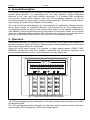
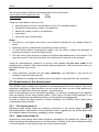
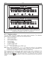
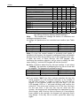
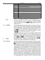
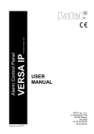
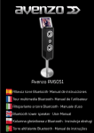
Fig. 1. View of the VERSA-LED-GR keypad.
The LED type keypad provides information on the alarm system status by means of 36 LEDs
and audible signals.
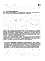
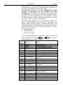
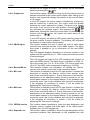
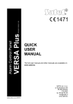
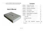
The LCD type keypad provides information on the alarm system status by means of a liquidcrystal display (2x16 characters), 6 LEDs and audible signals.
4
User Manual
VERSA
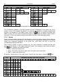
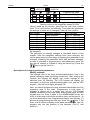
Backlighting of the keys and display in the LCD keypad may be permanent or automatically
activated by a keystroke or violation of the indicated zone of the control panel during the
armed mode. Operation mode of the backlight is specified by the installer.
Fig. 2. View of the VERSA-LCD-GR keypad.
5.1
LED functions
The LEDs provide information on the alarm system status and are designated by the
following symbols:
ALARM (red color) – alarm indicator, separate for each partition.
• Lit – indicates burglary alarm in the partition, goes off after the alarm is cleared.
• Lit with short extinguishments – burglary alarm occurred in the partition (alarm
memory).
• Blinking at a uniform rate (0.5s/0.5s) – fire alarm.
• Short blinks every 2s – fire alarm memory.
• Blinking at a uniform rate (1s/1s) – tamper alarm, tamper alarm memory.
• Blinking rapidly (0.25s/0.25s) – warning alarm; signal duration 30s.
• Blinking twice every 2s – indicates countdown of warning alarm time in partial
armed mode, if the time is longer than 30 seconds.
The ALARM LED for partition II lights up together with the TROUBLE LED after entering
the programming of service function settings (the first stage of programming).
ARMED
(green color) – armed mode indicator, separate for each partition.
• Lit – the partition is armed (optionally, the LED can be extinguished by the control
panel after the set time from 1 to 255 seconds after arming has elapsed – service
setting).
• Blinking – countdown of the partition exit delay.
VERSA
SATEL
TROUBLE
5
(yellow color) – trouble indicator.
• Blinking slowly – indicates that a trouble has occurred in the alarm system. The
LED goes off on arming one or two partitions, on clearing the cause of trouble or
after executing the current trouble check function (user function no. 7) and
clearing the trouble memory.
• Blinking rapidly – the control panel has entered the user function / service
function menu.
• Lit – programming the function settings or checking the armed mode.
(blue color) – indicator of the control panel operation in service mode.
• Lit – service functions available from the given keypad.
• Blinking – the control panel is in service mode, programming available from
another keypad.
SERVICE
1…30
(red color, LED type keypad only) – status indicators for the system zones.
Detailed information is given in the next section of this manual.
ZONE
5.2 LCD display functions
At its basic status, the LCD keypad can display date and time (format to be selected by the
installer) or keypad name. The following system statuses can also be indicated (the order as
per the display priority – from highest to lowest):
1. auto-arming delay countdown;
2. entry delay countdown;
3. exit delay countdown;
4. alarm from zone;
5. alarm in partition;
6. message service " System tamper, call service".
The messages on alarms from zones or partitions are displayed at the control panel
emergency status. If the alarm has been triggered from several zones, you can review the
names of those zones, using the arrow keys. Information on the alarm source is visible until
the alarm is cleared. The message content includes the name of zone or partition. The
installer decides whether such messages will be displayed.
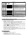
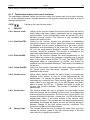
The LCD keypad will display the status of control panel zones after you press and hold down
the
key for approx. 3 sec. Numbers from 1 to 30, indicating the fields assigned to
individual system zones, are situated around the LCD display. Shown below are symbols
which can be displayed in those positions, as well as their meaning. The column next to the
symbols contains description of the lighting mode for LEDs representing individual zones on
the LED keypad. The order in the table indicates the event priority (from highest to lowest) –
the highest priority symbol is always displayed for the zone.
Note:
• If, when the control panel is in armed mode, a delayed zone is violated as the first one,
and then alarm is triggered by another zone, the first alarm memory will be assigned to
the zone which was violated first.
• If, after violation of a delayed zone, the armed mode is disabled without triggering alarm,
then the first alarm (violation) memory will be automatically cleared.
6
User Manual
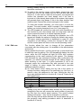
Priority
LCD
symbol
LED blinking mask
– OFF, – ON
VERSA
1
b
zone bypassed *)
2
D
long violation trouble *)
3
X
4
!
5
no violation trouble *)
memory of first violation in armed mode (the
zone triggered alarm in the partition or was
violated as first, but is no longer violated), the
first zone is indicated individually for each
partition,
violated tamper circuit of 2EOL zone
6
¦
7
s
8
a
Description
zone violated
zone triggered tamper alarm (tamper memory of
2EOL zone)
zone triggered alarm (alarm memory)
zone free (not violated)
(blank field) no detector type programmed for
the zone – no detector
*) States to be skipped (not displayed), if the partition to which the zone belongs is armed.
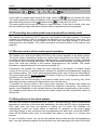
Table 1. Description of signaling the status of control panel zones on the keypad.
9
5.3 States signaled acoustically on the keypad
The keypad can generate the following beeps:
• one short – confirmation of a keystroke;
• two short – confirmation of entering the user function programming mode;
• three short – waiting for the code after partition armed mode is selected, disabling the
chime signaling on keypad (key
), disabling the controllable output;
• one long (duration approx. 1.5 s) – an attempt of arming, when the control panel is
not ready for supervision (some zones with the "priority" option enabled are violated or
[TROUBLE] LED lights up at the same time;
tampered); the
• two long – invalid code, unavailable function, canceled function or wrong function
data, exiting the timer programming function;
• three long – code recognized, but the function called is unavailable or execution of
the function is for some reason impossible at the moment;
• four short, one long – arming/disarming, exiting the service mode, correct
termination of the programming function, enabling the chime signaling on keypad,
activating the control panel controllable output.
Event signaling in the system:
• continuous beep – alarm;
• intermittent beep (0.25s/0.25s) – warning alarm;
• intermittent beep (0.5s/0.5s) – fire alarm;
• one long beep every 3 sec – signaling the exit delay countdown;
• two short beeps every 1.5 sec – signaling the entry delay countdown;
VERSA
SATEL
7
•
•
•
two short beeps every 2.5 sec – signaling a new trouble;
five short beeps – violation of a zone with "CHIME" option;
a series of beeps with diminishing duration every 5 sec – auto-arming delay
countdown.
The installer decides which events are to be acoustically signaled on the keypad.
Note : The last 10 seconds of exit delay countdown is signaled by a series of short beeps
ended by one long beep. The purpose of this way of signaling is to indicate the
moment of the countdown completion to the user.
5.4 Events signaled on alarm outputs
If the control panel armed mode is remotely controlled (e.g. by means of key fob), the
installer can enable the arming/disarming and alarm clearing signals on the siren control
outputs. If the output controls operation of a siren, the latter will generate short sounds (in
much the same way as in the car alarm systems). The signals have the following meaning:
• one short sound – arming;
• two short sounds – disarming;
• four short sounds – alarm clearing or disarming and alarm clearing.
Additionally, the alarm outputs signal the typical situations for the alarm system:
• continuous signal – burglary alarm;
• intermittent signal 1 s/1 s – fire alarm.
5.5 Signaling tamper alarm
Since the alarm installation is watched 24 hours a day, whether the system is armed or not,
violation of any component of the installation will trigger tamper alarm in the partition to which
the given component is assigned. Such an alarm may be signaled only on selected sirens,
which may be activated only when the control panel is in armed mode. The loud signaling
mode should be set by the installer of the system.
[ALARM] LED lights up and the
[TROUBLE] LED starts blinking
On the LED keypad, the
during the tamper alarm. On the LCD keypad, a message can be displayed, indicating the
alarm source. The alarm can be caused by:
• opening the enclosure (of control panel, expander, detector, siren or keypad);
• tearing off the enclosure from the wall (mounting surface);
• damaged cable, etc.
As each of the above situations can pose a threat to the security of protected premises, the
installer should be notified about the existing situation, so as to carry out inspection of the
installation and repair the faults, if any.
In order to encourage the user to take action, the installer can optionally enable the options
TROUBLE MEMORY UNTIL REVIEW and SERVICE MESSAGE AFTER TAMPER ALARM. In this case, the
"System tamper, call service" message will be displayed and the
[TROUBLE] LED will
start blinking when the alarm is cleared on the LCD keypad. The LED keypad will also signal
a trouble in the system and some LEDs may be blinking on it, if the tamper affects defined
zones of the control panel. The alarm source can be determined by viewing the log of current
troubles (user function no. 7).
The administrator (master) or an ordinary user can clear the alarm, but he cannot clear the
service message and the trouble memory. The message after tamper alarm can only be
cleared by means of the service code after the current troubles are reviewed and the trouble
memory cleared by using the
key when exiting the view function. If the cause of
8
User Manual
VERSA
reported tamper is not cleared, the trouble signaling will continue and the message will not
disappear.
If the SERVICE MESSAGE AFTER TAMPER ALARM option is not enabled by the installer, only the
[TROUBLE] LED will be blinking after the tamper alarm is cleared, and the date and time
will be displayed on the LCD keypad. The user with INSPECTION privilege will be able to clear
the trouble memory.
If the TROUBLE MEMORY UNTIL REVIEW is not enabled by the installer either, the trouble
signaling will end on clearing the tamper signal cause.
5.6 Signaling warning alarm
The installer can activate the WARNING ALARM function in the control panel. The warning alarm
function is aimed at limiting the number of false alarms caused mistakenly by the user when
disarming the system or moving around the premises where partial armed mode is activated.
The warning alarm is especially important in systems in which suppression of armed mode
information is used. If the user misses the time for disarming the system during the ENTRY
DELAY countdown or violates the indicated zone which is armed in the (night or day) partial
armed mode of the partition, the control panel can trigger the warning alarm. The warning
alarm, which is signaled on the keypad and, optionally, on the indoor siren, does not activate
reporting, messaging and/or outdoor signaling.
The warning alarm procedure is as follows. On violating the entry zone, the control panel will
start the ENTRY DELAY countdown. If the user fails to disarm the system, the control panel will
trigger acoustic signaling on the keypad (provided the signaling is active) by an intermittent
[ALARM] LED.
signal (0.25 s/0.25 s) for 30 seconds, as well as optical signaling by the
Next, the burglary alarm signaling will be set off. If the user can manage to disarm the
system, the burglary alarm will not be signaled.
In case of the warning alarm in partial armed mode, the installer sets the zones which, when
violated, can trigger the warning alarm in the same way as the entry zone. Different warning
alarm times can be programmed for each partition (up to 255 s). If the time is not
programmed, the warning alarm will last 30 seconds, as in the case of entry zone violation.
Irrespective of programmed time duration, the acoustic warning alarm on keypad will last for
the first 30 seconds.
Note: The warning alarm is generated only once after the system has been armed.
5.7 User codes
For everyday operation of the control panel, it is necessary to know the user code (the code
is a sequence of 4 to 8 digits from the 0–9 range). Entering the code should be completed
by pressing the key which corresponds to the operation you want to carry out. Details are
described below in this manual.
When entering the code, the keypad may show the number of entered characters of the
code. In the LCD keypad, asterisks are displayed in the lower line, illustrating the subsequent
code characters, while in the LED keypad, LEDs light up in succession, starting from number
16.
The code can control one or two partitions, can have different authority levels (user
schedules) and assigned name, depending on the selection made when entering a new user
or editing an existing one.
To each user code (except for the service code), it is possible to assign a proximity card or
another passive transponder and a key fob, which are used to control the alarm system
(arm/disarm; using the key fob, you can also control the control panel outputs, trigger special
alarms, activate the alarm signaling delay).
VERSA
SATEL
9
The following factory defaults are programmed in the control panel:
USER CODE NO. 30 (ADMINISTRATOR)
1111
SERVICE CODE
12345
Using any of the above codes you can:
• arm the system (in one or two partitions, in one of 3 available modes);
• change the armed mode in one or two partitions;
• disarm the system in one or two partitions;
• clear alarm;
• call up the user function menu.
Notes:
•
The SERVICE CODE
MODE).
•
•
Disarming can be combined with simultaneous alarm clearing.
To clear alarm without disarming the system, use the code to repeat the operation of
arming the system in one of the three modes.
The user menu gives access to number of functions described below in this manual. The
user has access to the functions which he is authorized to execute at the moment.
•
opens next menus and functions intended for the installer (SERVICE
Using the administrator's (master's) or service code enables 29 next user codes to be
programmed or deleted, if they have already been programmed. Using the service code, you
can delete all the user codes.
Notes:
•
•
Code properties, grouped into the user schedules, are described in the section on
creating a new user (see page 24).
The installer can change the authority level and names of the particular user schedules.
5.8 Armed mode of the control panel
The VERSA system enables two separate or overlapping partitions to be created. The zones
(detectors) belonging to both partitions can be armed as soon as one of the partitions is
armed or only after both of them are armed – service setting.
Each of the partitions can be controlled separately, i.e. arming or disarming of one partition
does not depend on the other partition status. If the code is to control both partitions, it can
be used to arm/disarm the selected partition or both partitions simultaneously.
In order to adjust the alarm system to various situations, the VERSA control panel offers
a few partition armed modes.
5.8.1
Full armed mode (1)
Operating mode during which the detectors connected to the control panel control the
indicated partition, and violation of the protected areas is signaled by the control panel with
all available means (monitoring, messaging, sirens, keypad).
5.8.2
Night armed mode (2)
Supervision mode during which some detectors indicated by the installer are inactive (e.g.
those monitoring the sleeping room or one floor area). Violation of the active detectors results
in normal reaction of the control panel, as in the full armed mode.
10
User Manual
5.8.3
VERSA
Day armed mode (3)
Supervision mode during which some detectors indicated by the installer are inactive (e.g.
those monitoring the interior of the whole apartment). Violation of the active detectors results
in normal reaction of the control panel, as in the full armed mode. Usually, the area within
which movement is possible inside the protected premises (partition) with activated day
armed mode is larger than with activated night armed mode.
5.8.4
Partition time parameters
Armed mode of the control panel is connected with the partition ENTRY DELAY and EXIT DELAY
times. The installer sets these time values separately for each partition.
After the partition has been armed, the user should leave the protected area. Depending on
the armed mode, different areas and elements of the premises are protected. The installer
should instruct the user, where he can move around after the given armed mode is activated.
From the moment of arming (irrespective of the type of armed mode), the control panel starts
signaling the EXIT DELAY countdown. The card readers and keypads may generate
appropriate sounds, and the
[ARMED] LEDs on the keypad start blinking. The LCD type
keypad will display information on the time left before arming the delayed zones (the instant
zones become active at once). If the exit delay countdown is running in both partitions, the
keypad shows the partition in which the countdown will be finished first, and then displays the
exit delay time for the partition which is not armed yet. The LED type keypad shows
symbolically the time before the partition is armed, by means of LEDs. The LEDs with
numbers 1-15 refer to the partition I, and the LEDs 16-30 – to the partition II. If the time
before arming is longer than 30 seconds, all LEDs are lit. If the time is reduced to below 30
seconds, then one LED goes out every 2 seconds, starting from number 15 for the partition I
and number 30 for the partition II.
Violation of the entry zone during the armed mode will start the ENTRY DELAY countdown.
Unless the partition is disarmed before expiry of the delay time, then after completion of the
countdown the control panel will start signaling the warning alarm or the regular alarm, if the
warning alarm function is not enabled. Violation of the instant zones, despite the ENTRY DELAY
countdown, may trigger the alarm. Signaling of the alarm may be delayed by the WARNING
ALARM TIME, if the warning alarm function is enabled.
The ENTRY DELAY countdown can be signaled, similarly as the EXIT DELAY countdown, by
a suitable acoustic signal and information on the LCD keypad display. In the LED keypad, by
contrast, all the LEDs (1-15 or 16-30) are blinking simultaneously during the ENTRY DELAY
countdown, symbolizing the time left until the partition I or II is disarmed.
Notes:
•
•
•
•
During arming, the exit delay countdown can be finished and the delays disabled. If
this is the case, violation of any armed zone (including the entry/exit and delayed ones) will
trigger instant alarm. In order to activate the armed mode with disabled entry delay, enter
the code and then press and hold down for approx. 3 seconds the key indicating the type of
armed mode. This function is mainly used when activating the day or night armed mode.
It is possible to change over between the control panel armed modes without disarming.
If, prior to changing over the armed mode, the control panel was signaling alarm, then
after change-over to another armed mode using the code, the alarm will be cleared. The
alarm signaling can also be cleared by "re-starting" the same armed mode in which the
control panel was before.
Changing over the armed mode will start signaling of the partition EXIT DELAY time, if it was
programmed and was not disabled by holding down the key. The user who remains in the
premises can disable the acoustic signaling in the keypad for approx. 60s by pressing any
numerical key.
VERSA
5.9
SATEL
11
Code arming
In order to arm the system, enter the code and press the key indicating the armed mode. If
you make a mistake when entering the code, press the
key and re-enter the code.
Enter the code carefully. Entering an invalid code 3 times may trigger an alarm (option
ALARM: 3 INCORRECT CODES enabled).
If the code is correct and the arming is possible, the control panel will confirm acceptance of
the command by four short beeps and one long beep and become armed. If the EXIT DELAY
has been programmed by the installer, the
[ARMED] LED will start blinking, the buzzer will
generate periodical beeps, indicating that the delay time countdown has started. The
ENTRY/EXIT and DELAYED zones will be armed after completion of the countdown, while the
INSTANT zones will be armed immediately.
The installer defines duration of the EXIT DELAY and the operating mode of acoustic signaling.
Example: arming by "VERSA" user code (digits: 83772).
Press in turn:
to activate full armed mode.
Press in turn:
to activate full armed mode.
Press in turn:
to activate night armed mode.
Press in turn:
to activate day armed mode.
Note : Using the sequence [CODE]
will only arm the system, when no partition is
armed and the control panel is not signaling alarm. If any of these situations occurs,
the sequence [CODE]
will disarm the system and/or clear the alarm.
If the code controls both partitions, the above mentioned method will arm both partitions in
the same mode. In order to arm just one partition or activate different types of armed mode in
different partitions using such a code (which controls both partitions), press in turn the key
with partition number and the key with armed mode type. After the partition and armed mode
are selected, the backlight of keypad keys will start flashing, which indicates that the code
should be entered now and the same armed mode confirmed.
Example:
Arm the second partition by the "VERSA" code in the night armed mode. The
code controls both partitions.
Press in turn:
In order to change the armed mode, if it is already activated, proceed exactly in the same
way as during the ordinary arming.
Note : The above described method for arming a single partition is only used when the quickarming function is not activated in the keypad. If this function has been started, then
arming a single partition or changing the partition armed mode need not be confirmed
by code.
The control panel may fail to arm the system, if:
• The control panel is not ready for arming: there are some installer defined zones,
which cannot be violated when arming ("priority" option) and one of such zones is
violeted – which is signaled by the control panel by one long beep, lighting up the
[TROUBLE] LED and displaying the names of violated zones on the LCD keypad.
If this is the case, wait a minute until all zones are free (in the LED keypad, the zone
status indicator LEDs go out; in the LCD keypad, the violation symbols disappear) and
reenter the code.
12
User Manual
VERSA
If some of the zones remain violated all the time (in the LED keypad, one of the LEDs
is always lit, and in the LCD keypad, the symbol denoting zone violation is displayed –
which may be caused e.g. by defective detectors), arming is possible after bypassing
that zone (by the user function no. 4).
Note:
When viewing the violated zones, the control panel enables such zones to be quickly
bypassed from the LCD keypad. In order to bypass the zone, press the
key. If
the zone can be bypassed by the user, the keypad will display a message with the
prompt whether the given zone is to be bypassed. Press the
key to bypass the
zone, and then the control panel will display information on the next violated zone, or
will arm the system, if all violated zones have already been bypassed.
• A tamper has occurred in at least one of the 2EOL zones.
• The code is wrong – this situation is signaled by two long beeps.
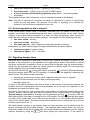
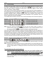
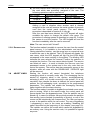
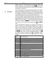
5.10 Quick arming
Provision is made for a quick arming, without any code, by pressing in turn two keypad keys.
It is possible to arm the first partition, the second partition or both partitions at the same time.
The first key selects the partition, the second one – the type of armed mode.
PARTITION I
PARTITION II
PARTITION I and II
FULL ARMED MODE
or
NIGHT ARMED MODE
or
DAY ARMED MODE
or
Table 2. Arming without code.
Using the quick arming procedure you can change the armed mode without disarming the
system. The armed mode can be changed to another one in each partition separately.
Note: Changing the armed mode without code will not clear alarm in the partition. Alarm can
only be cleared, when the armed mode is changed with the use of code.
The control panel may fail to arm the system, if:
• The control panel is not ready for arming (see: description in previous section of this manual);
• the function is disabled by the installer.
5.11 Disarming and alarm clearing
If one of the partitions is armed (the
[ARMED] LED is lit or blinking), alarming (the
[ALARM] LED is lit or blinking) or armed and alarming at the same time, entering the given
partition user code and confirming it with the
or
key will disarm the partition
and/or clear the alarm. The code controlling both partitions will disarm and clear alarm in both
partitions simultaneously (provided they are active). In order to disarm just one partition using
such a code, entering the code must be preceded by pressing in turn the key with partition
number and the
disarming key.
Example:
Disarm both partitions with "VERSA" code controlling both partitions.
Press in turn:
or
VERSA
SATEL
13
Example : Disarm partition II only with "VERSA" code controlling both partitions.
Press in turn:
If you make a mistake when entering the code, press the
key and reenter the code.
The control panel will confirm acceptance of the command by four short beeps and one long
beep and extinguishment of the
[ARMED] and/or
[ALARM] LED (if it is lit).
The control panel will not arm the system or clear the alarm, if the code is invalid or the user
has no suitable privilege. Refusal to clear the alarm is signaled by three long beeps.
5.12 Controlling the control panel armed mode with proximity cards
The installer can install the INT-IT proximity card reader in the alarm system. The device
enables one proximity card for controlling the partitions to be assigned to each user. The
control extent is limited by the privileges of the given user code and settings of the device
programmed by the installer. The control procedure is described below in this manual (see
page 36).
5.13 Remote control of the control panel operation
The installer can install the 433MHz INT-RX key fob control expander in the alarm system.
The device makes it possible to assign one remote control transmitter (key fob) to each user,
to enable remote arming and disarming, clearing alarms, triggering panic, auxiliary (medical)
or fire alarms, and controlling the outputs. The control extent is limited by the privileges of the
given user code and settings of the module, programmed by the installer. The control
procedure is described below in this manual (see page 37).
Furthermore, the installer can install any radio controller in the system, to enable remote
control of the key fob, or special buttons, intended for simplified arming/disarming, triggering
and clearing alarms. The control panel programmable zones can be used for this purpose.
The armed mode will be always activated by means of the key fob, irrespective of the status
(violation) of the control panel zones.
The installer can limit functionality of the armed mode control zone to arming only, while
disarming and alarm clearing will require that a user code be used.
To facilitate the remote control of the control panel operation, the installer can enable the
arm/disarm signaling by the acoustic or optical siren installed in the system. The method of
remote control depends on the installed devices and settings programmed by the installer.
The installer should instruct the user how the alarm system can be controlled by means of
the key fob.
5.14 Using timers in the alarm system
The user has access to programming four TIMERS. The timer ON/OFF time is programmed
separately for each day of the week and, additionally, the daily ON/OFF time is programmed.
Thus each timer can have two periods of activity per 24 hours. The modules can
automatically control the armed status of partitions or operation of the control panel
controlling outputs. 4 time exceptions can be programmed for each timer, when the ON/OFF
times will be different than usual. An exception can apply to one day or to a longer time
interval.
In case of partition control, you can set the partition armed mode and the arming/disarming
time. You may optionally program the arming time only, with disarming by the user or the other
14
User Manual
VERSA
way round. The timer can control one or two partitions. The installer will set the so-called TIMER
PRIORITY option for each partition. If the option is enabled, disarming will be always done by the
timer. If the option is disabled, partition will only be disarmed by the timer, if it was armed by the
timer. If it was armed by the user, it will remain armed until disarmed by user.
In case of output control, the user can only change the output (timer) ON/OFF time. The
numbers of controlled outputs and their operating modes are set by the installer. The output
can be active throughout the entire period of timer activity, can become active for a
programmed period of time or permanently (until deactivated by the user). The details of
timer programming are described on page 30.
5.15 Auto-arming deferment
Automatic control of the partition armed mode is connected with the arming deferment
function. The user who remains in the premises can defer the automatic arming for the time
programmed by the installer, using the suitable user function (see page 30).
The installer can program the AUTO-ARMING DELAY and the SIMPLE DEFERMENT option for the
partition. In such a situation, the control panel warns by a suitable acoustic signal that the
moment of arming is near, and the user can, during the delay time countdown, defer the
arming by pressing the
key twice. Arming can be deferred for time programmed by the
installer. The simple deferment can be limited to one-time use. If further deferments are
necessary, user code and the [6 1 #] user function must be used.
6. User Functions of "PRESS AND HOLD DOWN" Type
These functions are available to each user of the protected premises (without using the
code). To call them up, press and hold down the appropriate key for about 3 sec (until
acoustic signaling is triggered in the keypad).
6.1 Enabling/disabling the chime signal
Using this function (press and hold down the
key), you can enable or disable the chime
signal in the keypad (signaling violation of selected zones, when the control panel is disarmed).
If execution of the function is confirmed by four short beeps and one long beep, the signaling is
enabled, and if it is confirmed by three short beeps, the signaling in the keypad is disabled.
The LCD keypad will additionally display a message to confirm the operation.
The installer defines which zones will generate the chime signal when violated.
6.2 Changing the display mode
The function is only available in the LCD keypad. It can switch the LCD keypad display
modes between the date and time display and the graphical display of control panel zone
status. Meaning of the symbols describing the status of zones is shown on page 5.
6.3
Fire alarm
The function enables fire alarm to be triggered from the keypad. The control panel initiates
signaling on the keypad and on the FIRE ALARM, INTERNAL SIREN, EXTERNAL SIREN outputs and
sends the appropriate code to the monitoring station. The function may be disabled by the
installer.
6.4
Auxiliary (Medical) alarm
The meaning of this alarm can be defined, depending on the needs. The function can be
used for sending auxiliary alarm information to the monitoring station (it can be, for example,
a signal of calling for medical assistance, as adopted in the "Contact ID" monitoring format).
VERSA
SATEL
15
The function may be disabled by the installer.
6.5
Panic alarm
The function enables panic alarm to be triggered from the keypad. The control panel initiates
signaling on the alarm output, in the keypad and sends the appropriate code to the
monitoring station. The function may be disabled by the installer or limited only to the LCD
keypad (text message), monitoring and "PANIC alarm" output type (so-called silent panic
alarm).
6.6
Checking the armed mode
The function enables checking the partition status. It is particularly useful, when the function
extinguishing partition status indicator LEDs is enabled. On activating the function, the
keypad will light up the
[TROUBLE] LED and display information on armed / disarmed
mode.
In the LCD keypad, the message in the upper line of display refers to the partition I, and that
in the lower line – to the partition II. Similarly, in the LED keypad, information referring to
armed mode of the partition I is displayed in the upper line on LEDs 1-3, and the partition II –
in the lower line on LEDs 16-18. The full armed mode is shown by LEDs 1 and 16, the night
armed mode – by LEDs 2 and 17, and the day armed mode – by LEDs 3 and 18. If none of
the LEDs 1-3 or 16-18 is lit, the corresponding partition is disarmed. Press the
key to
reset the armed mode information. The function may be disabled by the installer.
7. Direct Control of Outputs
The installer can activate the so-called "QUICK CONTROL" function, which allows the user, by
means of keypad keys and without using any code, to easily control the functioning of control
panel outputs, and consequently, the functioning of electrical devices. One output to be
controlled can be assigned to individual keypad keys from
to
.
Press a numerical key and the
key to enable the output assigned to the given key,
permanently or for a programmed time period (up to 100 minutes 39 seconds). Press the
key to deactivate the output, if it was active.
numerical key and the
Example :
Deactivate the output 9 assigned to the key 9 and activate the output 10
assigned to the key 0.
Press in turn:
to deactivate the output 9;
to activate the output 10.
8. User Functions Available After Entering Code
The users (including the service) have access to functions useful during everyday operation
of the alarm system. For example, the timer settings or changing the service code are only
available from the user function level. Having entered the service mode, the installer can
program the user functions without any need for quitting this mode (service function 9).
To open the user function menu, described in this section, enter the USER CODE and confirm it
with the
key. The control panel will confirm entering the user function mode (the main
menu) by two short beeps and rapid blinking of the
[TROUBLE] LED. The functions are
numbered, so they can be called up by entering the number from the keypad (both LED and
LCD type). Having entered the user mode, press first the key with function number from the
main menu, and then the key with function number from the submenu (if any). After the key is
16
User Manual
VERSA
pressed, the LCD keypad will display the submenu name for two seconds, and then will open
the list of functions available in the submenu. Also the LED keypad will wait 2 seconds and
then it will enter the submenu.
Calling up the menu, submenu or function is acknowledged with two short beeps. In order to
enter the function settings and check or change the parameter values, select the function
number in the menu / submenu and press the
or
key. Generally, the possibility to
[ALARM] LED for the
change the settings of selected function is signaled by lighting up the
partition II and the
[TROUBLE] LED. For multi-stage functions on the LEDs designated
[ARMED] and
[ALARM] for the partition I and II, the next stage number is shown in binary mode.
The user function menu is dynamic and changes depending on the user's authority level.
Some functions are only available to the service, and some to the administrator only. The
LCD keypad does not display the names of functions which are not available. An attempt to
call up the number of function which is not available will be signaled by two long beeps, and
the keypad will remain in the recently called submenu. In such a situation, by pressing the
key you will enter the first available function from the given submenu. Therefore, pay
special attention to the keypad audible signals during the programming.
If a parameter value you have entered during programming is too high, press the
key
and the keypad will display the maximum permissible value and will remain in the function
waiting until the parameter is changed or re-confirmed. If, for whatever reason, the settings of
the given function cannot be changed, the control panel will signal it by two long beeps and
return to the basic mode.
Programming by means of the LCD keypad is easier, because of the display and the
capability of text presentation. The arrow keys enable a function to be selected from the list.
When you navigate through the user function menu, you can see a cursor on the left-hand
side of the display, which changes, depending on the indicated menu item:
- indicates submenu name;
- indicates function name.
Having entered a submenu, you will open a next selection list, while having entered
a function, you will be able to change its settings.
or
- scroll through list
or
- enter submenu or function
or
- exit function without changing the settings
- confirm the changes and exit the function
The way of changing the settings is described further in this manual. After exiting
the function, the keypad returns to its basic mode. To call up a next function, you must
reenter the CODE and confirm it with the
key.
If, having entered the function, the user will make no change or will make a change, but will not
confirm it, the keypad will return to the basic mode after 2 minutes (without saving any changes).
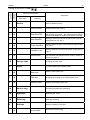
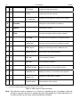
Shown below is a table with function numbers, function names in the LCD keypad, and
a short description. The # character at the function number means that after selection of the
function number you must press the
key to start the function or enter the settings
change menu.
VERSA
SATEL
17
Submenu
number
Main menu
number
Calling up the menu: CODE
0
Name in LCD keypad
Description
Main menu
Submenu
Service
Service related functions
0
0#
Service mode
Entering the service mode *)
0
1#
Start DwnlTEL
Starting telephone connection between the control panel
and the service computer – the control panel will call the
programmed telephone number of the service computer
0
3#
Start DwnlRS
Starting programming the control panel with computer
through RS-232 TTL port *)
0
4#
Finish DwnlRS
Ending programming the control panel through RS-232
TTL port *)
0
5#
Perman.sv.ac
Setting permanent access to the system for the service
code **)
0
6#
Access time
Time interval within which the installer can call up the
user functions and start the service mode by means of
the service code **)
1#
2
Change code
Changing the user code
Users
Functions related to the system users
2
1#
New user
Adding a new system user
2
2#
Edit user
Changing the settings of an existing system user
2
3#
Remove user
Deleting an existing system user
3#
Abort v.msg.
Canceling the telephone messaging
4#
Bypasses
Bypassing the zones
5#
Event log
Event log reviewing
6
Settings
Settings available to the users
6
1#
A-arm defer.
Deferment of auto-arming
18
User Manual
VERSA
6
2#
RTC clock
Programming the date and time
6
3#
Timers
Programming the timer settings
6
4#
Tel. numbers
Programming the telephone numbers to be notified
7#
Troubles
Viewing the current troubles or trouble log
8#
Control
Controlling the outputs
Tests
Functions for testing the alarm system operation
9
9
1#
Zone test
Functional test of the detectors connected to zones
9
2#
Output test
Functional test of the devices controlled by outputs
9
3#
ABAX sig.lvl.
Reading the radio signal level for ABAX devices
9
4#
Manual MS tst
Manual start of the test transmission
9
5#
MS1 test
Test of reporting to station 1
9
6#
MS2 test
Test of reporting to station 2
9
7#
VERSA version
Reading the version of control panel program
9
8#
Expander ver.
Reading the version of connected module program
9
9#
Supply volt.
Viewing the module supply voltages
9
0#
Outputs reset
Deactivating the active outputs
*)
**)
Functions available after entering the SERVICE CODE
Functions available after entering the ADMINISTRATOR CODE
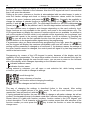
Table 3. Main menu of user functions.
Note : The refusal to enter a submenu or a function is signaled by two long beeps, while the
refusal to execute a function is signaled by three long beeps (e.g. when the function 21
is called up after all the users have already been entered).
VERSA
SATEL
19
8.1 Entering changes to the user functions
8.1.1
Options
Depending on the function, the control panel will make available for modification a single
option or a set of options (so-called multiple choice list).
In the LCD keypad, the option status is indicated by means of a special character in the right
upper corner of the display:
- option active (enabled),
- option inactive (disabled).
) to toggle the option status to the opposite one. Use
Press any numerical key (
the
keys to scroll through the list (if any) with text description. Pressing the
keys will take you to the graphical mode of option display, and also will move the
cursor indicating the number of option, the status of which can be changed.
In the LED keypad, the option status is indicated:
• for a single option – by brightness of the blinking LED no. 1
strong light - option active (enabled)
dim light
- option inactive (disabled)
• for a set of options (lists) – by lighting of the LED with number corresponding to the
option number in the list:
lit
- option active (enabled)
extinguished
- option inactive (disabled)
The
keys move the blinking cursor, indicating the number of option, the status of
which can be changed. The option status changes after any numerical key is pressed.
Having made the change, confirm the settings by pressing the
key.
8.1.2
Numerical data
Depending on the type of function, the data can be entered in the form of decimal or
hexadecimal numbers or alphanumeric characters.
LCD KEYPAD
Data can be edited on the LCD keypad by inserting a character with simultaneous shift of all
characters to the right of the insertion point. This mode is to be used when editing telephone
numbers and names. Another editing mode consists in overwriting, i.e. replacing the
indicated character by another one, entered from the keypad. The other characters do not
change their place. Such a mode is used for editing the code, time, etc.
• the
key delete the digit to the left of the cursor
• the
keys shift the cursor to the right or to the left
• numerical key inserts or overwrites the character at the cursor point (depending on
editing mode)
Note : When editing in the insertion mode, the last character of the number or name can be
deleted, if the total number of characters, after inserting the character in the middle,
exceeds the permissible number.
The DECIMAL NUMBERS are entered by pressing the corresponding numerical key.
20
User Manual
VERSA
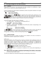
The HEXADECIMAL NUMBERS consist of digits 0-9 and characters A-F (see: Table 5). To enter
the digits 0-9, use the keys in the same way as for the decimal numbers, while to enter the
characters A-F, use the
or
key, pressing it (2, 3 or 4 times) until the required
character is displayed.
Key
Number of
keystrokes
1
2
3
4
2
A
B
C
3
D
E
F
Table 4. Way of entering the hexadecimal characters.
LED KEYPAD
In the LED keypad, you cannot correct the values of parameter being entered. If you have
made a mistake, exit the function and reenter it, so that the correct value can be entered.
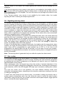
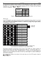
Three-digit numbers are displayed on LEDs 1-12, while the next digits in the longer numbers
are displayed on LEDs 16-27.
LED status
Digits and characters
0
1
2
3
4
5
6
7
8
9
– LED OFF
– LED ON
A
B
C
D
E
F
Table 5. Binary mode of presentation of decimal numbers (0-9)
and hexadecimal characters (0-F) by means of LEDs.
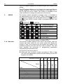
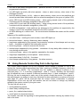
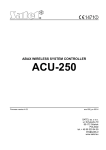
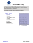
Each digit or character is presented in binary mode on four LEDs (see: Table 5). LEDs 1-4
present the first digit of the value being programmed, LEDs 5-8 – the second, LEDs 9-12 –
the third, 16-19 – the fourth, 20-23 – the fifth and 24-27 – the sixth one. The LED keypad can
display up to 6 first characters and does not show any further digits in numbers consisting of
more than 6 characters.
The HEXADECIMAL NUMBERS are entered in the same way as on the LCD keypad, using the
or
key.
VERSA
SATEL
21
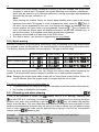
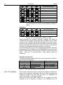
A
0
3
0
1
6
0
B
Fig. 3. Examples of presenting decimal values by means of LEDs in VERSA-LED-GR
keypad. In both examples, 3-digit values are programmed. Value 30 (030) has been
programmed in example A, value 160 - in example B.
8.1.3
Telephone numbers
The tone dialed TELEPHONE NUMBERS may contain special characters. The characters
programmed in the telephone number have the following meaning:
B
- switch to pulse dialing
C
- switch to tone dialing
D
- wait for additional signal
E
- 3-second pause
F
- 10-second pause
¾
- ¾ signal in DTMF mode
#
- # signal in DTMF mode
a, b, c, d
- other signals generated in DTMF mode
Note : Some special characters (#, *, a, b, c, d) occupy two positions in the telephone
number, thus reducing the maximum number of digits that can be programmed. The
character A (end of telephone number) is not to be programmed.
When programming the number, the special character input mode is displayed in the
upper right-hand corner. The [ABC] mode makes it possible to enter the upper case
letters, while the [abc] mode – the lower case letters. To change the mode of entering
characters, press the
key. Shown in Table 6 are characters entered in the particular
modes.
22
User Manual
VERSA
Characters available after next keystroke
mode [ABC]
key
#
1
key
1
2
B
C
3
D
E
F
mode [abc]
#
2
a
3
d
4
5
6
7
8
9
4
5
6
7
0
0
b
c
8
Table 6. Method of programming digits and special characters in telephone numbers.
The TELEPHONE NUMBERS in the LED keypad can be programmed in the same way as by
means of the LCD keypad. By default, on entering the telephone number programming
function, the keypad is in the [ABC] mode. Press the
key to change the mode from
[ABC] to [abc] and vice versa, however this type of keypad does not show in which mode it
currently is. It does not show characters entered in the lower case mode [abc] either.
8.1.4
Names
Some functions enable entering the text data (e.g. names of users, timers). Such data are
entered in much the same way as in the mobile phone. Subsequent keystrokes will display
letters and characters assigned to the given key. Hold down the key to enter the
corresponding digit into the name.
After making a pause or going to another key, the next character is entered into the next
position of the display. In the upper right-hand corner, the character input mode is shown.
key changes the letter input mode:
The
• [abc] – lower-case letters only
• [Abc] – first letter in the word: upper-case; the other ones: lower-case
• [ABC] – upper-case letters only
By default, editing starts in the [Abc] mode. Confirm the new name, using the
key.
Key
!
?
'
`
a
d
g
j
m
b
e
h
k
n
c
f
i
l
o
2
3
4
5
6
p
q
r
s
t
u
v
w
x
y
Characters available after next keystroke
"
{
}
$ % & @ \
^
|
#
1
]
0
7
8
z
9
.
,
:
;
+
/
= _ < >
(
)
Table 7. Characters entered by means of the keypad keys.
[
VERSA
SATEL
23
Name editing function is not available in the LED keypad.
8.1.5
Detailed description of the user functions
The description indicates, before the function name, the access path to the given function,
i.e. all the characters which must be pressed on the keypad to start the function or enter its
settings editing mode.
CODE
Calling up the user function menu.
0
SERVICE
0 0 # Service mode
0 1 # Start DwnlTEL
0 3 # Start DwnlRS
0 4 # Finish DwnlRS
0 5 # Perman.sv.ac
0 6 # Access time
1#
Change code
Calling up the function makes the control panel enter the service
mode, where the alarm system parameters can be programmed
by the installer. To quit this operating mode, call up the 0 0 # (QUIT
SRVMOD) service function. The function is only available after
entering the service code.
Calling up the function initiates the procedure of establishing
connection between the control panel and the service computer
via telephone line for remote programming of the alarm system
parameters and downloading of the event log. The control panel
will call the programmed telephone number under which the
computer should be available. The function is available to the
users with administrator and service authority level.
Calling up the function initiates the local programming of the
control panel by means of the computer connected with a special
cable to the control panel RS-232 TTL port. The DB9FC/RJ-KPL
designated cable is manufactured by SATEL and should be
available from the hardware distributor. The function is available to
the service.
Calling up the function terminates the local connection between
the control panel and the service computer. The function is
available to the service.
Option which defines whether the alarm system is permanently
available to the service, or only for a time programmed by the
administrator. To change the option status, call up the function
and press any numerical key. Press the key again to change the
option status to the opposite one. In the LED keypad, the option
status is shown by LED no. 1. Disable this option to make the
ACCESS TIME function available. The function is available to the
administrator.
The function allows the user to program the time length during
which the access will be available to the service for programming
and servicing the control panel. The time count is running from the
moment of exiting the function. Values from 1 to 255 hours can be
programmed. Value 0 will block access to the service. After
entering the function, if the access time has been preprogrammed
beforehand, the keypad will display the time left until the access is
blocked. Change of the time values must be confirmed. The
function is available to the administrator.
The function allows the user to change the code. After you have
entered the function, press in turn the numerical keys of the new
code (from 4 to 8 digits) and confirm it.
24
2
User Manual
USERS
The LCD keypad displays all the entered digits and enables code
editing.
The LED keypad displays up to 6 digits of the code and offers no
editing capability. If the new code consists of more digits, the 7th
and 8th digit will not be visible. The function is available to the
users authorized to change the code and to the service.
The function makes it possible to manage users. It is available to
the administrator and to the service. When entering a new user
and editing an existing user, the keypad shows on the
[ARMED]
and
[ALARM] LEDs at which stage of programming the user
currently is.
– LED OFF;
I
– LED ON.
Programming stage
II
Schedule number
1
2
3
4
5
Name
Simple
Arms only
Duress
Master
Select user for editing
Enter user code
Select schedule
Select partitions to control
Add key fob
Add proximity card
Edit user name
Table 8. Indication of consecutive stages of programming the
USER SETTINGS by means of keypad LEDs.
The function enables adding a new user to the system. After the
function has been called up, the control panel will display the
number of user to be entered into the system (the lowest of the
available numbers) and wait until the code is entered. The next
items describe the procedure of programming parameters
characterizing the particular user:
a) Enter the code and confirm it.
b) Select the user schedule number according to Table 9 data
(the LED with appropriate number will start blinking on the LED
keypad) and confirm.
Normal
2 1 # New user
VERSA
9
9
9
9
9
9
9
9
9
9
9
9
9
9
9
9
9
9
9
9
Right
Arming
Disarming
Alarm clearing
Tel. messaging cancel
Auto-arming defer
Zones bypassing
Change access code
9
9
VERSA
SATEL
25
9
Users editing
9
9
9
Control
9
9
Programming
9
DOWNLOAD/SERVICE
9
9
Inspection
9
9
Tests
9
DURESS
Key fob button functions (see: Table 12)
Button 1
39
39
39
43
39
Button 2
42
42
40
43
42
Button 3
53
53
41
43
53
Button 4
54
54
44
54
Buttons 1 and 2
44
Buttons 1 and 3
44
Table 9. Privilege assignment to particular user schedules and
key fob key functions (factory default settings).
Note:
The installer can change the names of schedules and
privileges assigned to them.
c) Assign the partition/s to be controlled and confirm (see Table
10).
Key number
Scope of control
LED indication
Partition I
LED no. 1 blinking
1
Partition II
LED no. 2 blinking
2
Partition I and II
LED no. 3 blinking
3
Table 10.
Note: If a key fob control module or proximity card reader is
installed in the system, the keypad in subsequent steps will enable
the key fob and then the proximity card to be assigned to the user.
If there are none of these devices, the LCD keypad, after
confirming the partition selection, will go over to editing the user
name (item j) ), and the LED keypad will exit the function.
d) Make a decision about the key fob and confirm. If you select
"nothing", the operation of assigning the key fob to a user will
be skipped. The keypad will proceed to item f).
Key number
Selection meaning
LED indication
Add
LED no. 1 blinking
1
nothing
LED no. 1 lit
2-9, 0
Table 11.
e) If you select "Add" (key fob), indicate whether the key fob
serial number is to be entered manually, or by means of
the INT-RX module. In order to read in the key fob by
means of the module, press the key with digit 1 (in the
LED keypad, LED no. 1 will start blinking) and confirm the
selection. The press and release one of the key fob keys
for the first time. If the key fob can be read into the
system, the keypad will acknowledge the operation by two
short beeps, and if the key fob is incorrect or it has already
been added to the system, the keypad will generate three
long beeps. If the key fob is correct, press the same key
again.
26
User Manual
VERSA
If the number is entered manually, you should only press the
confirmation key, enter the key fob number serial (which can
be found on the packing) and confirm it again.
The keypad will proceed to the stage of assigning the control
function to particular key fob buttons and their
combinations. The installer can program default functions of
the added key fob for each of the user schedules. When
editing a user, the default settings can be changed. To select
the function button number, use the numerical keys / arrow
keys (see: Table 12). Confirm the selection.
The LCD keypad displays the function names and allows the
user to scroll through the list to make his selection. If the
installer enters his own names of zones and outputs, the
keypad will display the entered names for the functions from 1
to 30 and from 51 to 102. The symbol of operation is shown
next to the output name:
1 - activate output
0 - deactivate output
/ - switch over output
The LED keypad displays the function number (from 001 to
102) on LEDs 1-12. Using the
and
keys, you can
scroll through list of function numbers.
Key
function
number
Name in LCD
keypad
0
1
2
…
30
31
32
33
nothing
Zone 1
Zone 2
…
Zone 30
Arm part.1 full
Arm part.1 night
Arm part.1 day
34
Dis/Clr part.1
35
36
37
Arm part.2 full
Arm part.2 night
Arm part.2 day
38
Dis/Clr part.2
39
40
41
Arm p.1&2 full
Arm p.1&2 night
Arm p.1&2 day
42
Dis/Clr part.1&2
43
44
45
46
51
Panic alarm
Silent panic
Fire alarm
Medical alarm
Output 1
:1
Notes
Button inactive
Function assigned to zone 1
Function assigned to zone 2
…
Function assigned to zone 30
Full arming in partition I
Night arming in partition I
Day arming in partition I
Disarming / Alarm clearing in
partition I
Full arming in partition II
Night arming in partition II
Day arming in partition II
Disarming / Alarm clearing in
partition II
Full arming in partition I and II
Night arming in partition I and II
Day arming in partition I and II
Disarming / Alarm clearing in
partitions I and II
Activating output 1
VERSA
SATEL
Activating output 2
…
: 1 Activating output 12
: 0 Deactivating output 1
: 0 Deactivating output 2
…
: 0 Deactivating output 12
Toggling output 1 (changing output
Output 1
:/
91
status to opposite)
Output 2
: / Toggling output 2
92
…
…
…
Output 12
: / Toggling output 12
102
Table 12. List of key fob button functions.
The control panel does not recognize whether the key fob has
2 or 4 buttons and will always require that 6 positions be
confirmed. The LED keypad does not indicate which key is
being programmed at the moment. The key fob buttons should
be programmed in the following order:
Key fob button
Key fobs
Key fobs
LCD keypad text
number
P-4, T-4
P-2, T-2
9
9
Buttn.1 fun. …:
1
9
9
Buttn.2 fun. …:
2
9
Buttn.3 fun. …:
3
9
Buttn.4 fun. …:
4
9
9
Buttn.5 fun. …:
1+2
9
Buttn.6 fun. …:
1+3
Table 13. Order of programming the key fob buttons.
After confirmation of the key 6 function (key fob buttons 1+3),
the control panel will proceed to editing the proximity card
(item f)).
key before
Note: Quitting the function by pressing the
confirmation of the last keystroke on the key fob means canceling
addition of the key fob.
f) Make a decision about the proximity card and confirm it.
If you have selected "nothing", the operation of assigning the
card to the user will be skipped. The LED keypad will terminate
the function and the LCD keypad will go to item j).
Key number
Selection meaning
LED indication
Add
LED no. 1 blinking
1
nothing
2-9, 0
Table 14.
g) If you have selected "Add" (the card), you should indicate,
using the arrow keys, the card reader to be used for reading
the card number, or proceed to entering the number manually.
In the LCD keypad, the reader should be selected from the list
of expanders by name (either entered or factory default one).
In the LED keypad, selection should be made from among the
LEDs representing the readers (the LED number corresponds
to the reader address on the expander bus). The following
numbers can be selected: 16, 17, 18, 19, 20, 21. The LED
which corresponds to the selected reader is blinking. Lack of
52
…
62
71
72
…
82
Output 2
…
Output 12
Output 1
Output 2
…
Output 12
27
:1
28
2 2 # Edit user
User Manual
VERSA
blinking means entering the number manually. The selection
should be confirmed.
h) To read in the card by means of the reader, present the card
briefly (for 0.5 s) to the reader face for the first time and then
remove it. If card can be read into the system, the keypad will
confirm the operation two short beeps, and if the card is
incorrect or it has already been added to the system, the keypad
will generate three long beeps. If this is the case, another card
must be read. Present the correct card again to the reader.
To enter the number manually, you must type it in from the
keypad. The card number, which is saved in the hexadecimal
format, can include characters from A to F (see page 19).
i) The LED keypad will confirm the card red-in and completion of
the function by four short beeps and one long beep, and the
control panel will return to its normal operating mode.
j) After reading in the card or skipping this operation, the LCD
keypad will enable the option to change the default user name.
The name entering procedure is described on page 22. After
completion of the editing, confirm the change of user name,
and the control panel will return to its normal operating mode.
The function allows the user to change all the parameters
connected with the existing user. It is available to the administrator
and service.
Having started the function, use the arrow keys or numerical keys
to select the user for editing. The LCD keypad will display the user
name, while the LED keypad will light up LEDs with numbers
corresponding to the users existing in the system. The blinking
LED indicates the user selected for editing. After confirmation the
selection, you should proceed through all the editing stages as
when entering a new user. If a given parameter is not to be
changed, press the confirmation key and proceed to the next
stage of editing. At some stages the control panel provides
additional selection options:
a) An extra feature when editing the key fob is the option to
change functions assigned to the particular key fob keys, or
remove a key fob assigned to the user. Editing the key fob
keys was described above in function 2 1, item e). Press one of
the keypad keys:
Key number
Selection meaning
LED indication
Add
LED no. 1 blinking
1
Edit keys
LED no. 2 blinking
2
Delete
LED no. 3 blinking
3
nothing
4-9, 0
Table 15.
Adding a key fob in situation when another key fob is already
assigned to the user will remove the serial number of previous
key fob from the control panel memory. The control related
settings will remain – they can be changed or confirmed.
After the key fob has been deleted, the control panel will go to
the proximity card editing procedure which is described in
function 2 1, item f).
VERSA
SATEL
29
b) An extra feature when editing the card is the option to remove
the card which was previously assigned to the user. The
following operations can be carried out
Key number
Selection meaning
LED indication
Add
LED no. 1 blinking
1
nothing
2, 4-9, 0
Delete
LED no. 3 blinking
3
Table 16.
Adding a card in situation when another card is already
assigned to the user will remove the serial number of previous
card from the control panel memory. The card adding
procedure is described in function 2 1, item g).
After the card has been deleted, the LCD keypad will make
available the option to change the default user name. The
procedure of entering names is described on page 22. Confirm
the names to end the function. The LED keypad will end the
function immediately after the card is removed.
Note: The user cannot edit "himself".
2 3 # Remove user
3#
ABORT V.MSG.
4#
BYPASSES
The function makes it possible to remove the user from the control
panel memory. It is available to the administrator and service.
Having started the function, use the arrow keys or numerical keys
to select the user to be deleted. The LCD keypad will display the
user name, while the LED keypad will light up the LEDs which
correspond to the users existing in the system. The blinking LED
indicates the user selected for removal. Confirm the selection to
complete the function. The user cannot delete himself. The service
can delete all users – in such a situation the SERVICE CODE has
permanent access to the system and is the only code that can
control the system. The service has also permanent access in the
situation, when all users with the DOWNLOAD / SERVICE right
will be removed.
Starting the function will cancel (terminate) the telephone
messaging which is currently under way. The messaging can be
started by triggering alarm in the system, arming/disarming,
activating a zone, or a trouble occurring in the system. If it is not
cancelled, then, despite the alarm is cleared, the control panel will
perform the full messaging cycle, according to the programmed
parameters. The installer can enable the messaging canceling
option together with the alarm clearing.
The function makes it possible to bypass the selected zones once,
prior to arming. When in the armed mode, the control panel will
ignore signals from the bypassed zones. Thus the partition can be
armed e.g. in case of a detector failure which prevents the partition
from arming (zone checked for possibility of arming), or one of the
rooms can be intentionally left unsupervised. The user can bypass
a zone in the partition which he can control. The way of bypassing
/ unbypassing a zone is the same as enabling / disabling the
option described at the beginning of this chapter (see page 19).
The installer can define the zones which cannot be bypassed by
an ordinary user. Using the service code, it is possible to bypass
any zone.
30
5#
User Manual
EVENT LOG
6
SETTINGS
6 1 # A-arm defer.
6 2 # RTC clock
6 3 # Timers
VERSA
Calling up this function will enable (re)viewing the event log. The
function is only available from the LCD keypad. The events are
sorted chronologically by date and time of their occurrence. Using
the
arrow keys you can go to the previous/next event
saved in the control panel memory. To display additional
information (e.g. name of user, zone, partition, module, etc.) for
some events, press the
or
key. Keypad will also
automatically display the additional information, if no key is
pressed for 5 seconds. To quit the function, press the
key.
The function makes it possible to defer the auto-arming when the
partition is controlled by timer. The DEFERMENT TIME is
programmed by the installer. The user can defer the arming not
later than when the AUTO-ARMING DELAY is being signaled by the
keypad. Calling the function again during the DEFERMENT TIME
countdown will restart the deferment time countdown.
The function makes it possible to program the current time and
date indicated by the keypad. Correct indications of the clock are
important, so that the actual course of events in the protected
building can be reconstructed, if necessary.
After starting the function, the LCD keypad will display the current
settings and prompt by text messages which parameters should
be entered. In the first step, the time should be programmed, in
the second – the date. The change of data should be confirmed.
The LED keypad, after the function has been started, will display 6
decimal digits, indicating the time at the moment of calling up the
function. The data are displayed in the following format:
HHMMSS (HH – hours, MM – minutes, SS – seconds), of which
the first three digits are displayed on LEDs 1-12, and the next
three digits on LEDs 16-27 (see page 19). To change the hour
settings, enter 6 digits and confirm the change. After
confirmation, the keypad will display the next 6 digits with the
following meaning:
YYMMDD (YY – two last digits of the year, MM – month, DD –
day). Now you can enter the next 6 digits and change the date or
exit the function without changing the date.
The function allows the user to change the settings of timers
controlling the partition armed mode and/or operation of control
panel control outputs. Armed mode can be programmed for each
partition as well as timer/armed mode activation and deactivation
time.
In the timer settings, it is possible to program only e.g. the arming/
disarming times which control the partition armed mode. Entering
the numbers 99:99 in the time positions will disable the given
function of the timer.
When programming the timer settings, the keypad indicates on the
LEDs designated
[ARMED] and
[ALARM] at which stage of
the programming the user currently is.
VERSA
SATEL
– LED OFF;
I
31
– LED ON.
II
Programming stage
Select timer for editing
What is to be changed?
Change parameter settings
Table 17. Indication of successive stages of programming the
TIMER SETTINGS on the keypad by means of LEDs.
Having called up the function, press the key with timer number
(from 1 to 4) and confirm the selection. Then select the parameter
the settings of which are to changed (Table 18) and confirm.
Key number
Selection meaning
LED indication
Week schedule
LED no. 1 blinking
1
Exception 1
LED no. 2 blinking
2
Exception 2
LED no. 3 blinking
3
Exception 3
LED no. 4 blinking
4
Exception 4
LED no. 5 blinking
5
Arm. mode part. 1
LED no. 6 blinking
6
Arm. mode part. 2
LED no. 7 blinking
7
Table 18. Selection of timer parameter to be changed (What is to
be changed?).
The procedure of entering changes is described further in this
chapter. After the parameter settings have been changed, the
control panel returns to the stage of selecting the parameter to be
changed, indicating the parameter which has just been changed.
In order to proceed to programming a next parameter, press the
key with its number or indicate it using the arrow key. Press the
key to quit the function.
Description of changing particular parameters:
Weekly schedule
The settings refer to the timer activation/deactivation time in the
normal operating mode (excluding exceptions). After entering the
function, the keypad will display the current settings of the
selected timer for Monday. The LCD keypad will display full
information on the timer activation/deactivation time, and the LED
keypad – only the first 6 digits (see page 20).
Next, you should program the timer activation/deactivation time for
respective days of the week. Programming in both types of
keypads is carried out in a similar way, but the LCD keypad
enables corrections to be made when entering data, while the LED
keypad does not. Enter 8 digits in the HHMMHHMM format, the
first 4 of which refer to the timer activation time, and the next 4 – to
the timer deactivation time. Programming begins from Monday. To
proceed to programming the next day, press the
key. If the
timer is to be active everyday in the same period of time, you can
program only the last position of the calendar ("DAILY") and
confirm it.
32
User Manual
I
Table 19.
VERSA
II
Programming stage
Monday
Tuesday
Wednesday
Thursday
Friday
Saturday
Sunday
Daily
Indication of successive stages of programming TIMER
ACTIVATIONS/DEACTIVATIONS on the keypad by means of
LEDs.
Exception
I
II
Programming stage
Begin exception (date)
End exception (date)
Exception arm/disarm
Table 20. Indication of successive stages of programming
EXCEPTION on the keypad by means of LEDs.
Having entered the exception settings, program two dates to
indicate the time interval during which the exception is to be valid.
6 digits in the YYMMDD format (two last digits of the year, month,
day) are to be programmed. Each of the dates must be confirmed.
On the other days, beyond the set interval, the basic timer settings
will apply, as programmed within the WEEKLY SCHEDULE.
In the next step, the time of timer activation/deactivation should be
programmed. Enter 8 digits in the HHMMHHMM format, where the
first four digits mean the time of timer activation, and the next four
digits – the time of its deactivation. The settings should be
confirmed.
Partition armed mode
To select the armed mode, press the key as described in Table 21
and confirm the selection.
Key number
Selection meaning
LED indication
Full armed mode
LED no. 1 blinking
1
Night armed mode
LED no. 2 blinking
2
Day armed mode
LED no. 3 blinking
3
Nothing
4-9, 0
Table 21. Selecting the partition armed mode.
6 4 # Tel. numbers
The function allows the user to change the telephone numbers to
which voice message notifications are sent. When changing the
telephone number, the user has the option to reprogram the
control panel without calling the installer.
After the function has been called up, the keypad will make
available a list of telephone numbers to be changed (up to 8
VERSA
7#
SATEL
TROUBLES
33
items). Using the numerical keys or arrow keys, select the
telephone number to be changed and press
. Then, enter
the new telephone number and confirm the change. If the number
requires entering special characters, program them according to
the description on page 22.
The LED keypad will only display the first 6 digits of the number
selected for change, and also the first 6 digits of the new number.
The function enables reviewing the current troubles and clearing
the trouble log. The installer can program the control panel so that
it can display information on troubles even after they have been
cleared until making a review and clearing the trouble log.
In the LCD keypad, using the arrow keys you can scroll through
the trouble log and familiarize with the details. Descriptions of the
stored troubles, the cause of which has already been cleared, are
designated with the letter "P" in the right-hand upper corner of the
display. On pressing the
key, the control panel will display
the message "Clear trouble memory? 1=Yes". Press the key
[TROUBLE]
to clear the trouble memory and extinguish the
LED.
In the LED keypad, the troubles are presented symbolically by
means of LEDs. The LED number corresponds to the type of
trouble. A permanently lit LED denotes current trouble, a blinking
LED – trouble memory. The meaning of LEDs is described in
Table 22. Some of the LEDs serve as common trouble indicators
(e.g. for zones, key fobs, expanders). To exit the function, press
the
key. Once the key has been pressed, the
[TROUBLE] LED on the keypad will start blinking rapidly. To clear
. Pressing another
the trouble memory, press the key
numerical key will exit the function without clearing the trouble
memory.
LED
Trouble description
number
1
230 V AC loss
2
Control panel battery trouble
3
Telephone line voltage loss
4
Telephone line signal trouble
5
OUT1 trouble
6
OUT2 trouble
7
KPD power trouble
8
AUX power trouble
9
Reporting trouble – monitoring station 1
10
Reporting trouble – monitoring station 2
11
Wireless system jamming
12
Communication bus short circuit
13
Clock loss
14
RAM memory error
15
Mainboard TMP open
16
Zones – tamper
17
Zones – long violation
34
User Manual
18
19
20
21
22
23
24
25
26
27
28
29
30
Table 22.
VERSA
Zones – no violation
Zones – masking
Wireless device battery low
Wireless device communication loss
Module tamper
No presence (module)
AC loss (module)
Battery trouble (module)
Power output overload (module)
Low battery (key fobs)
Module restart
Control panel restart
HSE (processor) system trouble
Meaning of individual LEDs during trouble review.
Note:
In order to end signaling trouble no. 30 it is necessary to restart
the control panel. To do so, terminate the trouble reviewing
function by pressing in turn the
and
keys. If, after the
restart, the keypad is still signaling a trouble, you must clear the
trouble memory.
8#
CONTROL
9
TESTS
The function enables changing the status of "CONTROLLED" type of
outputs. After the function is started, the LCD keypad will display
the list outputs which can be controlled. Using the arrow keys you
can scroll through list and select the output to be controlled. Press
the
key to activate the output permanently or for a
preprogrammed time (up to 100 minutes 39 seconds). Pressing
the
key will deactivate the output, if it is active.
In the LED keypad, the output to be controlled is shown by the
blinking indicator. The arrow keys make it possible to move the
indicator to another position to be controlled. Activating and
deactivating is performed in the same way as in the LCD keypad,
(keys
and
). The lit LED denotes active output, and
the extinguished LED - inactive. To exit the function, press
.
A group of functions, available to the users with TESTS right. Only
the ZONE TEST function is available to the installer only.
A function facilitating the start-up and control of the alarm system.
After the function is called, the keypad will light up permanently the
[TROUBLE] LED. In the other keypads, this LED will be blinking.
Indicate duration of the test (from 01 to 15 min.) and confirm. The
LCD keypad will display in graphical mode the current status of
zones, whereas the LED keypad will start blinking with its LEDs
corresponding to the system zones. For the violated zones, the
LEDs will be lit permanently. Then, proceed to carrying out the by
walking around the protected premises, opening the doors,
windows, etc., in order to verify the correct functioning of particular
detectors and zones of the control panel. The keypad will signal
each zone violation by 5 short beeps, and a symbol of given zone
violation will light up on the LCD display. The symbol will be visible
until the end of the test. The LED keypad will light up permanently
the corresponding LED. Violation of the 24H ALARM zones during
9 1 # Zone test
VERSA
9 2 # Output test
9 3 # ABAX sig.lvl.
9 4 # Manual MS tst
9 5 # MS1 test
9 6 # MS2 test
9 7 # VERSA version
9 8 # Expander ver.
SATEL
35
the test will not trigger any alarm. The function can be terminated
earlier by pressing the
key.
The function makes it possible to carry out the functional check of
devices connected to the control panel outputs. After calling up the
function, the keypad will display information on the current status
of 12 outputs.
In the LCD keypad, the active output is indicated by a large dot,
and the inactive by a small one. The cursor under the symbol
indicates the output selected for testing. The arrow keys enable
the cursor to be moved to the next position. Pressing the
key activates the selected output, and pressing the
key
deactivates. Moving the cursor the next position or terminating the
function with the
key will restore the initial status of the
tested output.
In the LED keypad, the blinking LED means that the output with
the given number is active (enabled). The blinking LED indicated
the number of output which can be tested.
The function enables the user to check the level of radio signal
received from particular devices of the ABAX system. The arrow
keys make it possible to go to information on the next ABAX
devices.
The LCD keypad displays information on the zone number in the
system and the signal level in %. 100% means the maximum level
of received signal.
The LCD keypad will light up the LED indicating the number of
zone with ABAX device. The signal level is indicated on LEDs 1630 for the zones from 1 to 15, or on LEDs 1-15 for the zones from
16 to 30. The 100% level corresponds to lighting up 15 LEDs.
This function initiates the procedure of sending the MANUAL
TRIGGER TEST REPORT event code to the monitoring station.
The function is available from the LCD type keypad. It initiates the
procedure of sending the MANUAL TRIGGER TEST REPORT event
code to the monitoring station 1. During execution of the function,
descriptions of the operations being currently carried out by the
control panel appear on the keypad display. If any problems with
monitoring occur, this function enables their cause to be detected.
If the progress of monitoring is correct, it will be ended by
displaying the "Event sent" message.
The function is available from the LCD type keypad. It initiates the
procedure of sending the MANUAL TRIGGER TEST REPORT event
code to the monitoring station 2. During execution of the function,
descriptions of the operations being currently carried out by the
control panel appear on the keypad display. If any problems with
monitoring occur, this function enables their cause to be detected.
If the progress of monitoring is correct, it will be ended by
displaying the "Event sent" message.
The function makes it possible to check the type designation and
firmware version (number and build date) of the control panel.
Available from the LCD keypad only.
The function makes it possible to check the type designation of the
connected modules, their addresses on the expander bus and
36
9 9 # Supply volt.
9 0 # Outputs reset
User Manual
VERSA
firmware version (number and build date). The arrow keys enable
the user to scroll through the list of modules identified in the
system. Available from the LCD keypad only.
The function makes it possible to check the supply voltage for the
connected modules. The keypad will display the symbol of device,
its address on the modules bus and the value of measured supply
voltage. Available from the LCD keypad only.
The function makes it possible to deactivate the so-called LATCH
outputs (without limitation of cut-off time) which cannot be reset by
entering the CODE and
(e.g. the outputs of CHIME, ZONE
VIOLATION, CONTROLLED, “DURESS” ALARM type).
If the output of FIRE DETECTOR POWER SUPPLY type is used in the
system, using the function will deactivate such an output for 16
seconds in order to clear the alarm memory of fire detectors.
9. Using Proximity Cards for System Control
The control panel can work in conjunction with the INT-IT proximity card reader. By using
a proximity card or another passive transponder working at frequency 125 kHz, it is possible
to arm or disarm partitions and clear alarms. The reader can control one or two
partitions, and a different type of armed mode can be activated for each partition (full, night,
day).
Built in the reader are three LEDs (red, green and yellow) and a buzzer for audible signaling,
which provide information on the system status. Operating mode of the device is
programmed by the installer, who should instruct the user how to use the proximity card.
Using the reader consists in presenting the card to the reader face for a short-time (0.5 s) or
longer (min. 2 s), and then removing the card from the reader. After the card is presented and
held for about 2 s, the reader will light up the red LED, then after the next 2 s it will extinguish
the red LED and light up the green one, then after the next 2 s it will extinguish the green
LED and light up the yellow one, then after the next 2 s it will extinguish the yellow LED.
Removing the card when one of the LEDs is lit will activate the armed mode according to the
schedule assigned to the given LED. Removing the card when none of the LEDs is lit will not
change the partition armed mode status.
Short presentation – disarming, alarm clearing
Long presentation – arming in one of the three schedules set by the installer (assigned to
the LED color):
1. red LED – one or two partitions fully armed
2. green LED – one or two partitions armed in the mode set by the installer
3. yellow LED – one or two partitions armed in the mode set by the installer
Note: In the green or yellow LED mode you can also program disarming any partition, if it
was armed before presenting the card to the reader.
Meaning of the light signaling:
• red LED lit – partitions armed according to the schedule assigned to the red LED
• red and green LEDs lit - partitions armed according to the schedule assigned to the green
LED
• red and yellow LEDs lit - partitions armed according to the schedule assigned to the yellow
LED
VERSA
SATEL
37
• red LED lit with short extinguishments – partitions armed in a mode inconsistent with the
programmed schedules
• red LED lights up briefly with short pauses – alarm or alarm memory, when none of the
partitions is armed
• red LED blinking slowly (1s/1s) – alarm or alarm memory, when one or two partitions are
armed (armed mode inconsistent with the schedules assigned to the green or yellow LED)
• green LED lit and red LED blinking slowly – alarm during armed mode of the partitions,
consistent with the schedule assigned to the green LED
• yellow LED lit and red LED blinking slowly – alarm during armed mode of the partitions,
consistent with the schedule assigned to yellow LED
• all LEDs extinguished – both partitions are disarmed or the partition not supported by the
reader in none of the schedules assigned to the LED is armed
• all LEDs blinking at a uniform rate – no communication between the reader and the control
panel
Meaning of the audible signaling:
• one short beep – reading the card number; a next LED lights up
• three short beeps – arming / disarming, alarm clearing
• long beeps separated by long pauses, terminated by a series of short beeps and one long
beep – countdown of partition exit delay after arming
• three long beeps – refusal to execute the function
• double beeps separated by long pauses – countdown of entry delay after violation of entry
zone during armed mode
• continuous beep – alarm in the partition operated by the reader
• long beeps separated by a short pause – alarm memory
• intermittent beep (0.5s/0.5s) – fire alarm
• short beeps separated by a long pause – fire alarm memory
10. Using Remote Control Key Fob in the System
The control panel supports the INT-RX expander which makes it possible to use in the
system the remote control transmitters (key fobs), working at 433MHz frequency, which are
manufactured by SATEL. The four-button key fob enables 6 different functions to be
executed (keys 1, 2, 3, 4 and key combinations: 1 and 2, 1 and 3). Similarly, the two-button
key fob allows the user to execute 3 different functions (keys 1, 2 and combination 1 and 2).
One key fob can be assigned to each user of the system, except the service. The installer or
the administrator can assign to each key fob button/ button combination a number of function
(see page 27) which will be executed after the button/ button combination is pressed.
Replacement of the user key fob with another one will not delete or change any settings
related to the system control by the given user.
The key fob can serve as:
• arming/disarming switch,
• alarm delay enabling button,
• panic, fire, medical alarm button,
• on/off switch for electrical devices.
The installer can start the signaling of arming/disarming and alarm clearing by means of key
fob on the siren.
38
User Manual
VERSA
11. Short Description of Keypads
armed (supervision)
lit – partition armed
blinking – exit delay countdown
alarm
lit – alarm in partition
blinking – alarm memory
service – signaling control panel operation in service mode:
lit – service mode available on this keypad
blinking – service mode available on another keypad
LCD display – date and time / status of supervision
zones
HASŁO+
- czuwanie pełne (1)
- czuwanie nocne (2)
- czuwanie dzienne (3)
- wyłączenie czuwania,
skasowanie alarmu
trouble – signaling
detection of a technical
problem in the system –
check by means of user
function no. 7
VERSA-LCD-GR
– hold down for 3 sec to switch
the display to indicating status of
control panel supervision zones:
b – zone bypassed
L – long violation trouble
N – no violation trouble
! – first alarm memory
– violated tamper circuit of 2EOL
zone
¦ – zone violated
t – tamper circuit of 2EOL zone
triggered alarm (tamper memory)
a – zone triggered alarm (alarm
memory)
– zone free (not violated)
– (nothing) detector type not
programmed – no detector
VERSA-LED-GR
LEDs 1÷30 – lighting mode indicates
status of control panel supervision
zones ( – OFF, – ON):
– zone
bypassed
– long violation
trouble
– no violation
trouble
– first alarm
memory
– violated
tamper circuit of 2EOL zone
– zone
violated
– memory of
2EOL zone tamper
– zone
triggered alarm (alarm memory)
– zone free
(not violated)
VERSA
SATEL
– hold down for 3 sec to trigger
PANIC ALARM
– hold down for 3 sec to trigger
AUX (MEDICAL) ALARM
– hold down for 3 sec to trigger
FIRE ALARM
CODE+
– user functions:
0 Service
00# – Service mode
01# – Start telephone connection
03# – Start RS connection
04# – Finish RS connection
05# – Permanent service access
06# – Service access time
1# Change code
2 Users
21# – New user
22# – Edit user
23# – Delete user
3# Abort tel. messaging
4# Bypasses
5# Event lon
6 Settings
61# – Auto-arming deferment
62# – RTC clock
63# – Timers
64# – Telephone numbers
7# Troubles
8# Control
9 Tests
91# – Zone test
92# – Output test
93# – ABAX signal level
94# – Manual test transmission
95# – Test monitoring station no. 1
96# – Test monitoring station no. 2
97# – VERSA version
98# – Expander versions
99# – Supply voltage
90# – Reset outputs
39
Control of partitions assigned to code:
CODE+
- full armed mode
- night armed mode
- day armed mode
- disarming, alarm clearing
Quick arming partition I:
+
- full armed mode
- night armed mode
- day armed mode
Quick arming partition II:
+
- full armed mode
- night armed mode
- day armed mode
Quick arming partition I and II:
+ lub
+
- full armed mode
- night armed mode
- day armed mode
– press twice to defer auto-arming
– hold down for 3 sec to display information on
armed mode
VERSA-LED-GR:
Partition I
LED 1 ON – full armed mode
LED 2 ON – night armed mode
LED 3 ON – day armed mode
LED 1,2,3 OFF – disarmed
Partition II
LED 16 ON – full armed mode
LED 17 ON – night armed mode
LED 18 ON – day armed mode
LED 16,17,18 OFF – disarmed
– hold down for 3 sec to enable / disable
chime signaling
SATEL sp. z o.o.
ul. Schuberta 79
80-172 Gdańsk
POLAND
tel. + 48 58 320 94 00
[email protected]
www.satel.pl