1
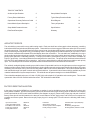
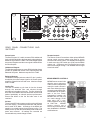
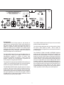
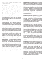
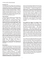
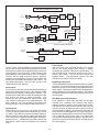
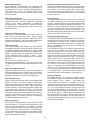
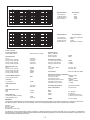
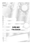
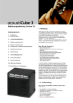
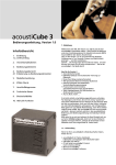
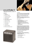
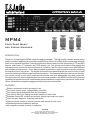
MPM4
Four Zone Music
and Paging Manager
INTRODUCTION
Thank you for selecting the MPM4 music and paging manager. This high quality, versatile device can be
used in countless applications to provide comprehensive control of multiple audio sources and distribute
them to four separate locations. Features include four stereo inputs for audio connection of CD and MP3
players, radio tuners, TV receivers and DVD players, etc.; four priority inputs which allow paging and
automatic music override for announcements or a jukebox, and four mono output zones with balanced
and unbalanced connections. A four-band equalizer is provided on each input and output for enhancing
the overall sound of the system. The simple and intuitive front panel displays the source routing to each
zone with metering to indicate signal levels and presence. Front panel pushbuttons and volume controls,
or a remote control in each zone, make source selection and level adjustments easy and convenient.
Occupying two rack spaces and designed for continuous operation, the MPM4 includes all the features
necessary to operate most multi-zone sound system installations in night clubs, sports bars, health clubs,
offices, restaurants or anywhere paging and/or priority inputs are required.
FEATURES
Simple, convenient controls are easy to use
Four mono output zones, independently controlled
Four source inputs assignable from the front panel
Four priority inputs for paging and audio insertion to each zone
Separate 4-band EQ on each source input, priority input and zone output
Input trim gain stages for matching input levels
Optional remote control of source selection and volume in each zone
Password protected installation settings
No computer required for setup or operation
whirlwind
99 Ling Road - Rochester, NY 14612
800-733-9473 / 585-663-8820 Fax: 585-865-8930
Website: http://www.whirlwindusa.com
TABLE OF CONTENTS
Architects Specifications
2
Setup Modes Description
8
Factory Reset Initialization
2
Typical Setup Procedure Guide
9
Operational Summary Reference Guide
3
Block Diagram
10
Normal Mode System Description
4
Theory of Operation
10
Setup Mode Password Access
5
Specifications
12
Rear Panel Description
6
Warranty
12
ARCHITECTS SPECS
The unit shall be a monaural four zone audio routing matrix. Each zone shall have a front panel volume attenuator, controlling
both balanced XLR and unbalanced RCA output jacks. There shall be an eleven segment LED meter and a clip LED to monitor
the audio output level. The unit shall have four stereo source inputs, via unbalanced RCA jacks, summed to mono and assigned
to the zones through a front panel four by four switching matrix. Routing assignments shall be made by an “input first” or “zone
first” selection method and illuminated LEDs shall display the active connections. The unit shall have, additionally, four mono
priority audio inputs whose signal can override or mix with source inputs in any zone to which the priority input is assigned. The
priority inputs shall have a cascading hierarchy. Priority Input 4 shall be overridden by Priority 3, both 3 and 4 overridden by
Priority 2, and Priority 1 overrides all others that are assigned to the same Zone. The priority inputs shall have balanced female
XLR and TRS, and unbalanced RCA connections. Input select, pad and ducking switches shall be provided on each priority
input. The unit shall provide connection to optional remote control accessories for volume and source selection.
The unit shall use digital signal processing to provide functions of input audio level trim on all eight inputs, maximum output level
setting on all four outputs, twelve four band equalizers, priority signal output gain and zone assignment with ducking, LED meter
monitoring of all functions, four by four source routing matrix, and four zone volume attenuators. All functions shall be adjusted
and controlled through front panel controls and rear panel switches. A password lockout feature shall be available to prevent
unauthorized alteration of system setup functions. The unit shall store all system settings in non-volatile EEPROM.
The unit shall be standard rack mount, 19” wide 3.5”(2RU) high, with a depth of 10” behind the rack mounting ears. The unit shall
operate with 100 to 250 VAC 50/60Hz and be fan cooled. The unit shall be model MPM4.
FACTORY RESET INITIALIZATION
In the event of moving the MPM4 from one installation to another, it may be desirable to return the settings of the unit to their
factory default condition. Disconnect the power from the unit and locate the two-pin shorting jumper on the back of the display
circuit board behind the LED matrix inside the MPM4. (See diagram on page 5.) Remove the jumper plug and push it onto the
Factory Reset pins #1 and #2 located on the three-pin reset header to the left. Apply power, wait for the turn on sequence to
complete and remove power. Return the two-pin jumper plug to it's storage pins. This will restore the following initial factory
settings.
Input Trim Controls
In and Zone EQ Controls
Zone Max Level Controls
Priority Trim Controls
Priority EQ Controls
Minimum
Flat
Minimum
Minimum
Flat
Password
Zone Volume Controls
Source Inputs to Zone Outputs
Priority Assign Controls
2
Unlocked, Set to (Z1,Z2,Z3,Z4)
Maximum
No Routing Assignments
No Assignments, Minimum Level
MPM4 NORMAL MODE CONTROL SUMMARY
MODE
NORMAL
MODE
PRIORITY
ACTIVE
MODE
MATRIX AREA ACTIONS
ENCODER/METER AREA ACTIONS
There are two methods to assign an input to an output, Input First or
Zone First. Press an 'In' button first and it will light. Then press all
'Zone' buttons that you want that input assigned to. Repeat for other
inputs. Press the lit input to exit this mode. Press a 'Zone' button
first and it will light, then press an 'In' button to assign it to that Zone.
This also disconnects any other input assigned to that Zone. Press
the lit Zone to exit this mode. The matrix LEDs light to show
assignments.
Encoders act as Zone Master Volume Attenuators. The Meters
display output level into each Zone normalized to Zone Max
Level. Clip LED monitors zone output or the active input to the
Zone.
An incoming priority signal lights the corresponding Priority Input
LED. Routing LEDs in the Zones that have this Priority Input
assigned to them flash while the Priority Input is active. Any Source
Input routed to this Zone is affected by the setting of the rear panel
Ducking Level switch. Multiple Priority Inputs assigned to the same
Zone operate with cascading hierarchy within that Zone.
Control Range
Meter Range
-80dB to 0dB
-36dB to +12dB
Same as normal mode, except for Priority Input 1 and 2 Zone
Level Override switches On. In this case their audio is sent
directly to the Zone at the Zone Max Level setting and the
Volume Controls are inactive.
Control Range
Meter Range
-80dB to 0dB
-36dB to +12dB
MPM4 SETUP MODE CONTROL SUMMARY
SETUP
PASSWORD
ACCESS
INPUT TRIM
MODE
MATRIX AREA ACTIONS
ENCODER/METER AREA ACTIONS
To gain access to Setup Mode, press and hold the Mode Select
button until the In and Zone buttons on the left illuminate. Enter the
password code sequence on them and then press and release the
Mode Select button. To change the password, simultaneously push
and release the Zone 1, Zone 4 and Mode Select buttons. Push the
desired combination of buttons and enter it by pushing the Mode
Select button, which will begin flashing. The password sequence
must be correctly repeated and entered with the Mode Select button
to validate it.
Encoders act as Zone Master Volume Attenuators. The Meters
display output level into each Zone normalized to Zone Max
Level. Clip LED monitors zone output or the active input to the
zone.
All four 'In' buttons light and stay on until mode is exited. It is not
possible to assign anything in this mode
Encoders are input level controls for source inputs 1-4. Meters
measure preamp outputs. Clip LED monitors source input only.
Control Range
Meter Range
Control Range
Meter Range
IN & ZONE
EQ MODE
The flashing 'In' or Zone button indicates which 4 band Equalizer is
active through the encoders.
Assign the loudest desired Source or Priority Input to the Zone and
set the maximum level by optimizing the output gain of the MPM4 to
the inputs of the zone power amps.
All four 'In' buttons flash while this mode is active. It is not possible to
assign anything in this mode. Line level inputs will require the rear
panel Pad switches to be on.
-15dB to +15DB
-15dB to +15dB
Encoders are output gain stage controls for each Zone. Meters
show output level. 0 LED is 0dBv at the XLR. Clip LED
monitors Zone Output or the active Input to the Zone.
Control Range
Meter Range
PRIORITY
TRIM MODE
-20dB to +20DB
-36dB to +12dB
Encoders become four band EQ controls. Meters show the
amount of cut or boost. Center LED is flat. Clip LED monitors
zone output or the active input to the zone.
Control Range
Meter Range
ZONE MAX
LEVEL
MODE
-80dB to 0dB
-36dB to +12dB
-60dB to +20DB
-36dB to +12dB
Encoders are input level controls for Priority inputs 1-4. Meters
measure preamp outputs. Clip LEDs monitor Priority Inputs
only.
Control Range 0dB to +60DB
Meter Range
-36dB to +12dB.
PRIORITY
EQ MODE
The flashing 'In' button indicates which Priority Input 4 band
Equalizer is active through the encoders.
Encoders become four band EQ controls. Meters show the
amount of cut or boost. Center LED is flat. Clip LED monitors
zone output or the active input to the zone.
Control Range
Meter Range
PRIORITY
ASSIGN MODE
The flashing 'In' button designates which Priority Input has been
activated and can be assigned to any or all Zones by pressing the
'Zone' buttons. While that Input is active, its level can be set in any
Zones that it has been assigned to. In unassigned zones the
Control Position Indicator LED is set to minimum. Select other
Priority Inputs and repeat the assignment and level setting process.
3
-15dB to +15DB
-15dB to +15dB
Encoders are level controls for the active priority input into the
zones that it is assigned to. The meters display output level
into each zone normalized to zone max level. Clip LED
monitors Zone Output or the active Input to the Zone.
Control Range
Meter Range
-20dB to +20DB
-36dB to +12dB
Routing
Priority Inputs
In 1
1
In 2
2
3
4
Input Trim
In & Zone EQ
In 3
Setup
Mode
Zone Max Level
In 4
Normal Mode
ZONE 1
ZONE 2
ZONE 3
ZONE 4
MODE SELECT
On the right side of the control surface are the Level Meters
and Volume Controls for adjusting the level in the four
Zones. The Level Meters monitor the current amplitude of
the audio, relative to the Zone Maximum Level that was
preset in the Setup procedure. The Volume Controls, in
Normal Mode, are signal attenuators with a range of 0dB to
80dB of attenuation. Turned all the way up, the output
level of the MPM4 is determined by the setting of the Zone
Max Level control. (See Setup Mode.) When the Volume
Controls are moved, the LED meter display dims and a
single LED showing the relative position of the Control
illuminates brightly. Under each Volume Control is a Clip
LED that displays signal clipping at the Zone Output or of
any input assigned to that Zone Output.
NORMAL MODE SYSTEM DESCRIPTION
The MPM4 takes advantage of its comprehensive setup
functions to provide the system operator with a simple and
intuitive set of controls for selecting audio sources and
setting system volumes in any of the four output zones.
Normal Mode
On the left side of the control surface is the Routing section
with pushbuttons for each of the four Source Inputs on the
left side and each of the four Zone Outputs across the
bottom. The Matrix of green LEDs displays the current
Input to Output signal connections. Only one In may be
assigned to any Zone at a time. Assignments can be made
in one of two ways, by first selecting an Input or first
selecting a Zone.
In the center of the control surface are the Priority Input
LEDs and the Setup Mode LEDs. The Setup Mode LEDs
are off in Normal Mode.
Input First
Depress any In button and it will light. This input can
now be assigned to any Zone by depressing the
desired Zone buttons. Pushing the Zone button a
second time will disconnect the In from that Zone.
Depress other In buttons for further connections.
Depress the lit button a second time to exit this mode.
Priority Active Mode
Priority Inputs replace, or mix with, the Source Inputs in
any Zone to which they are assigned. When a Priority
Input signal is received, the corresponding Priority Input
LED illuminates. The Routing Matrix LEDs in the Zones
that have this Priority Input assigned to them flash while
the Priority Input is active. Any Source Input routed to this
Zone is affected by the setting of the corresponding rear
panel Ducking Level switch. There are four Priority Inputs
that operate with cascading hierarchy within each Zone.
Priority Input 4 is overridden by Priority 3, both 3 and 4 are
overridden by Priority 2, and Priority 1 overrides all others
that are assigned to the same Zone. Typical Priority Inputs
could be prerecorded announcements, a particular music
source, such as a jukebox, or a paging microphone.
Paging microphones used with the MPM4 should have an
ON/OFF switch.
Zone First
Depress any Zone button and it will light. Any In can
now be assigned to this Zone by depressing the
desired In button. Pushing the In button a second
time will disconnect it from that Zone. Depress other
Zone buttons for further connections. Depress the lit
button a second time to exit this mode.
4
+12
+6
+12
+6
+15
+3
0
-3
-6
-12
flat
+3
ZONE
1 -12
-18
0
-3
-6
flat
ZONE
2 -12
Level Low EQ
Clip
-6
flat
ZONE
3 -12
-15
Level
Lo Mid
Clip
-6
flat
ZONE
4
-24
-30
-36
0
-3
-18
-24
-30
-15
0
-3
+15
+3
-18
-24
-30
+12
+6
+15
+3
-18
-24
-36
+12
+6
+15
MPM4
-30
-36
-15
Level
Hi Mid
Clip
-36
-15
Level
Hi EQ
Clip
MUSIC-PAGING
MANAGER
SETUP MODE PASSWORD PROTECTION
ACCESS
The MPM4 is equipped with a lockout function to prohibit
unauthorized modification of the system setup
parameters. Setup Mode is accessible to the system
installer in new units and the Mode Select button is
illuminated to indicate this condition. A default password
sequence (Zone 1, Zone 2, Zone 3, Zone 4) is encoded in
the unit, but only becomes effective when the Mode Select
button is held in for four seconds, which activates the
password and denies access to the Setup mode. The
Mode Select light goes out and only Normal Mode is
available to the system operator.
In the event Setup Mode adjustments are required and the
password is unknown, it is possible to reset the MPM4
back to the default password. Disconnect the power from
the unit and locate the two-pin shorting jumper on the back
of the display circuit board behind the LED matrix inside
the MPM4. Remove the jumper plug and push it onto the
Password Reset pins #2 and #3 located on the three-pin
reset header to the left. (See diagram.)
Unlocking Setup Mode
To gain access to Setup Mode, press and hold the Mode
Select button until the In and Zone buttons on the left
illuminate. Enter the password code sequence on them
and then press and release the Mode Select button. The
Routing display will blink once if the correct code sequence
has been entered, and the Mode Select button will
illuminate to indicate that the Setup Mode functions are
unlocked. Entering an incorrect code will return the MPM4
to Normal Mode.
Changing the Password
Custom passwords can be created by the system installer
to protect the settings of the Setup Mode. Passwords can
be from 0 to 8 characters long and are created from
pushing a pattern of the In and Zone buttons.
RESET JUMPER VIEW
CAUTION: CONFIRM POSITION OF THE JUMPER PLUG
BEFORE REPOWERING WHEN DOING A PASSWORD
RESET. IF THE PLUG IS MISTAKENLY PUT ONTO THE
FACTORY RESET PINS #1 AND #2, ALL SYSTEM
SETTINGS WILL BE RESET TO FACTORY DEFAULTS
AND THE CURRENT SETUP WILL BE LOST.
To change the password, simultaneously push and
release the Zone 1, Zone 4 and Mode Select buttons. The
In and Zone buttons on the left all illuminate. Push the
desired sequence of buttons and then activate it by
pushing the Mode Select button, which will begin flashing.
The password sequence must then be correctly repeated,
followed by pushing the Mode Select button to validate it.
Successful reentry will cause the Routing display to flash
twice and the Mode Select button to be fully illuminated.
An incorrect verification sequence will cause the MPM4 to
exit the Password Change mode. Setup Mode is still
accessible and the previous valid password is still
recognized by the MPM4.
Apply power, wait for the turn on sequence to complete and
remove power. Return the two-pin jumper plug to its storage
pins. The password is now reset to (Zone 1, Zone 2, Zone 3,
Zone 4) and Setup Mode is automatically unlocked.
5
PAD
REMOTE CONTROLS
XLR/
RCA
REAR PANEL CONNECTIONS AND
SWITCHES
Source Inputs
The Source Inputs 1,2,3 and 4 are stereo RCA unbalanced
jacks, which feed signal to the front panel routing switches.
Maximum signal level is +24dB. The Left and Right signals
are summed together and the mono signal is distributed to
the Zone Outputs.
Remote Controls
The Remote Control Connections allow optional MPM4R
remote control accessory plates to be used for source
selection and volume control. One MPM4R can be placed
in each zone using CAT5 cable up to 1500' from the MPM4
master unit. Connectors are 8 pin RJ45 plugs on both
ends wired straight through. The MPM4R uses all eight
wires in the cable.
Unbalanced Outputs
The Unbalanced Outputs are mono RCA jacks that always
provide an unbalanced version of the output signal at the
balanced XLR jacks. Maximum output level is +16dB.
Balanced Outputs
The Balanced Output jacks are male XLR, pin 2 positive,
that deliver the master output signal to the sound system
amplifiers. Signal is line level and mono. Maximum output
level is +22dB.
MPM4R REMOTE CONTROLS
MPM4R remote control units
allow the user to select any
of the four Source Inputs and
control the audio volume in
each Zone without having to
access the main MPM4 unit.
One MPM4R can be used in
each of the four Zones.
Connections between the
MPM4R and the main unit
are made through RJ-45
jacks using CAT 5 wire.
Cable length can be as long
as 1500 feet.
MPM4R
remote controls use a
Decora style insert plate for
easy installation in standard
electrical boxes.
Cooling Fan
The Fan is installed to pull clean air into the chassis
through the attached filter and exhaust through
perforations in the sides of the unit. The filter helps keep
the inside of the MPM4 clean and should be removed and
washed periodically to maintain optimum performance.
Ensure that airflow to the fan and side vents is not
restricted.
AC Inlet
The universal IEC inlet connects to the incoming AC line to
the Power Supply. The MPM4 operates with 100-250VAC
and is rated at 25 Watts. All settings of the MPM4 are
saved in non-volatile memory through power cycling. The
MPM4 powers up with the same settings that it had when
power was removed. All settings are recorded ten
seconds after any control change is made.
6
FOUR ZONE MUSIC & PAGING MANAGER
MODEL MPM4 MADE IN USA
WHIRLWIND - ROCHESTER, NY USA
www.whirlwindusa.com
PAD
PAD
XLR/RCA
ON
XLR
OFF
RCA
C
PAD
PAD
US
PRIORITY
ZONE
VOLUME
OVERRIDE
ON
XLR/ XLR/
RCA RCA
XLR/
RCA
Priority Inputs
The MPM4 has four Priority Inputs for the insertion of
paging, music, announcement or other audio signals into
the Zone Outputs. The audio from the Priority Inputs is
added to or replaces Source Input audio in any Zone to
which the Priority Input is assigned. The Priority Inputs
assigned within each Zone have a cascading hierarchy
with signal input on P3 muting P4; input on P2 mutes P3
and P4; and input on P1 mutes all three.
OFF
The XLR/RCA Switch selects which input connector feeds
audio to the priority signal chain.
The PAD Switch attenuates the incoming audio of either
the XLR or RCA inputs by 20dB. This is useful for
controlling high level signals that could clip the electronic
preamp stages.
The PRIORITY ZONE VOLUME OVERRIDE Switches
select how the Priority Input signals from P1 and P2 are
delivered to the Zone Outputs. In the OFF condition, the
audio from all four Priority Inputs is delivered to the Zone
Outputs identically: prior to the current setting of the Zone
Volume Controls. This means that the priority signal level
will be no louder than the current setting of the Volume
Control in each Zone. When the Override switches are on,
the Priority Input 1 and 2 audio is fed to the Zone Outputs at
the level determined by the setting of the Zone Max Level.
This bypasses the current setting of the Zone Volume
Control and sets the Ducking Level of any Source Input to
70dB, regardless of the Ducking Level switch position.
The MIC/LINE female XLR Input accepts balanced mic or
line signals with levels up to +24dB. Phantom power is
automatically supplied at +15VDC to power most
commercial condenser microphones. Paging mics with
ON/OFF switches are recommended to prevent the
Priority Input from triggering accidentally.
The stereo RCA Inputs accept unbalanced line audio up to
+24dB. The Left and Right signals are summed together
and the mono signal is distributed to the Zone Outputs.
The DUCKING LEVEL Switch sets the amount of volume
reduction of the Source Input in the Zone Outputs when the
Priority Input is active. In the 0 position, the source signal
and the priority signal are mixed together with no change in
the source signal level. At -20 the source signal is reduced
by 20dB and at -70 the source signal is effectively turned
off leaving only the priority audio signal.
7
Zone Max Level. An appropriate maximum volume for the
listening environment can be established by setting the
audio level going to each Zone Output. This feature allows
the installer to determine the maximum level of all audio
inputs into each zone by coordinating the output gain of the
MPM4 to the inputs of the Zone power amps. This is an
analog final output gain stage with 20dB of gain and 60dB
of attenuation, adjustable in 1dB steps. Each encoder
detent equals 1dB. Unity Gain is at the 0 position of the
Control Position Indicator LED.
Output gain, in
conjunction with the of gain and attenuation in the Input
Trim controls and the Priority Assign function allow
manipulation of the signal levels to achieve balance
throughout the system.
SETUP MODE SYSTEM DESCRIPTION AND
USER INTERFACE
The MPM4 is a powerful, feature-filled audio
router and controller. Using the available control
functions, the system installer can make all the
adjustments necessary to provide a transparent,
simple audio manager for the system operator.
Once the system has been properly adjusted, a
password lockout code can be enabled to protect
the setup from unauthorized alterations.
Parameters that can be adjusted include:
Priority Input Level Trim. The audio level at the Priority
Inputs can be adjusted to compensate for varying output
levels from different types of sources. The Trim level
adjustment range is 0dB to +60dB. Each encoder detent
equals 1dB. The available gain is used to increase paging
mic signals to line level. Line level inputs will require the
use of the Input Pad. This is activated by pushing the rear
panel switch associated with each Priority Input.
Source Input Level Trim. By trimming all of the Source
Inputs to the same level, the volume in the zones remains
uniform when switching between them. The Trim level
adjustment range is ±20dB in 1dB steps. Each encoder
detent equals 1dB.
Source Input EQ. A four-band equalizer with a ±15dB
range of adjustment is available on each Source Input for
optimizing its sound. The Lo Mid center frequency is
600Hz and the Hi Mid is 2.5kHz. These are peaking filters.
The Low and Hi frequency bands are shelving types with
different characteristics in boost or cut mode. The Low EQ
boost curve is a shelving type filter with a nominal roll-off
frequency of 80Hz. The Low EQ cut curve has a 12dB per
octave slope with a sliding roll-off frequency. As the
amount of cut is increased, the frequency shifts upward.
Nominal frequency points are 20Hz to 250Hz. The Hi EQ
boost curve is a shelving type filter with a nominal roll-off
frequency of 8kHz. The Hi EQ cut curve has a 12dB per
octave slope with a sliding roll-off frequency. As the
amount of cut is increased, the frequency shifts downward.
Nominal frequency points are 15kHz to 2.5kHz. The EQ
Controls make changes in 1dB increments that are
displayed on the Control Position Indicator LEDs. Each
1dB detent in the Control corresponds with a change in the
display providing precise adjustment throughout the
±15dB range.
Priority Input EQ. A four-band equalizer with a ±15dB
range of adjustment is available on each Priority Input for
optimizing its sound. The Lo Mid center frequency is
600Hz and the Hi Mid is 2.5kHz. These are peaking filters.
The Low and Hi frequency bands are shelving types with
different characteristics in boost or cut mode. The Low EQ
boost curve is a shelving type filter with a nominal roll-off
frequency of 80Hz. The Low EQ cut curve has a 12dB per
octave slope with a sliding roll-off frequency. As the amount
of cut is increased, the frequency shifts upward. Nominal
frequency points are 20Hz to 250Hz. The Hi EQ boost
curve is a shelving type filter with a nominal roll-off
frequency of 8kHz. The Hi EQ cut curve has a 12dB per
octave slope with a sliding roll-off frequency. As the amount
of cut is increased, the frequency shifts downward.
Nominal frequency points are 15kHz to 2.5kHz. The EQ
Controls make changes in 1dB increments that are
displayed on the Control Position Indicator LEDs. Each
1dB detent in the Control corresponds with a change in the
display providing precise adjustment throughout the
±15dB range.
Zone Output EQ. A four-band equalizer is available on
each of the mono Zone Outputs. The range of all four
bands is ±15dB. The Lo Mid and Hi Mid are peaking filters
with frequency centers at 250Hz and 1.6kHz. The Low
and Hi are shelving filters with corner frequencies of 20Hz
and 10kHz. The Lo Mid frequency control peaks at 250Hz,
which enhances upper bass in ceiling/wall mount type
speakers. The Hi Mid frequency control was chosen at
1.6kHz to enhance voice frequencies. The EQ Controls
make changes in 1dB increments that are displayed on the
Control Position Indicator LEDs. Each 1dB detent in the
Control corresponds with a change in the display providing
precise adjustment throughout the ±15dB range.
Priority Assign. This feature assigns the Priority Inputs to
the Zone Outputs, using the Input First method, and sets
the level of each channel of priority audio within each zone.
The Routing Matrix is used to make the assignments and
the rotary controls are used to set the priority level relative
to the Source Inputs. The adjustment range is ±20dB in
1dB steps. Each encoder detent equals 1dB. In
unassigned zones, the Control Position Indicator LED on
the level controls is set to minimum. Priority Input 1 and
Priority Input 2 have an extra switch on the rear panel that
allows the Priority Input signal to bypass the current setting
of the Zone Volume Controls. With the switches on,
Priority Input 1 and 2 audio is sent directly to the Zone
Outputs at the level determined by the Zone Max Level
setting and all other inputs will be ducked to –70dB
regardless of the position of the Ducking Switch.
8
TYPICAL SETUP PROCEDURE
Installation Tip
To facilitate the most expedient setup experience, it
may be desirable to do the initial setup with the MPM4
unit physically in each Zone. If a paging mic is to be
used in the zone, that wire can be used with adapters
to send the output of the MPM4 back to the power
amps in the system equipment location. Pulling a
shielded audio pair along with the CAT 5 wire for the
remotes would also make this possible. After the
initial setup and EQ with the paging mic in each Zone,
the MPM4 can be installed in the equipment location
and each input adjusted as required.
Select the Priority Assign mode and clear all Priority
Assignments (all Routing LEDs off) in the desired
Zone. Assign Priority In 1 to the Zone and set the level
control to minimum. Connect the paging mic to
Priority Input 1. Select the XLR with the XLR/RCA
switch and switch the Pad Off. Depress the Priority
Zone Level Override P1 switch to On. Select Priority
Trim Mode and turn on the mic. Adjust the Priority
Trim level, leaving enough headroom to avoid
clipping with maximum level peaks. Return to Priority
Assign mode and make sure that the In 1 Switch is
flashing. Slowly bring up the Volume Control in the
desired Zone until the microphone audio is at a
moderate level. Go to Priority EQ mode and make
sure that the In 1 Switch is flashing. The sound of the
microphone can be optimized with the 4-band
equalizer.
System Startup
Connect the power amplifiers to the speakers and to
the Zone Outputs of the MPM4. LEAVE THE
POWERS AMPS OFF. Connect a known reference
audio source to one of the Source Inputs. Apply
power to the MPM4, turn the Zone Volume Attenuator
Controls fully up and enter the Setup Mode. If the
Mode Select switch is not illuminated, press and hold
it for approximately four seconds to enter the
Password Unlock function. Enter the password and
press the Mode Select switch again. The switch
should illuminate and allow selection of the various
Setup Mode functions. Select the Input Trim mode
and turn all four level controls down to minimum.
Check the settings of the In and Zone EQ, adjust
them to flat if they are not. Enter the Zone Max Level
mode and adjust the Volume Controls to minimum.
Turn on the power amps and turn their input levels up
to a desired starting position. Turn on the reference
audio source, select Input Trim and set the input level
of the to a nominal level, about –6dB. Return to Zone
Max Level mode, select the Source Input and slowly
bring up the Volume Control for each Zone toward
unity gain as indicated by the Control Position
Indicator LED. Unity Gain is at the Flat or –6,
position. Adjust the amplifier input controls to
establish an initial appropriate volume for the
coverage area. Use the Zone EQ to optimize the
speakers to the listening area. Turn off the Source
Input audio.
Fully optimizing a paging mic involves properly
structuring the gain stages of the MPM4. It is
desirable to have a paging mic that operates only
when spoken directly into and not be triggered by
ambient noise. The Priority Trim gain stage is before
the Priority Threshold Trigger.
This allows
adjustment of the trigger level required to activate the
Priority Input. In the Priority Assign mode, the
Volume Controls set the level of the Priority Input
signal feeding into the Zone Max Level gain stage.
Balance the gain between these two stages to
achieve adequate headroom and sufficient system
drive level. If a hotter drive signal is desired from the
MPM4, select Zone Max Level and boost the signal
above unity. This process establishes Zone Max
Level and all other inputs can now be set up in relation
to it.
Source Inputs can be added and balanced at a lower
volume. Turn off the Priority Zone Level Override P1
switch on the rear panel. Return to Normal Mode and
reduce the Zone Volume Controls. Assign Source
Inputs to the desired Zones. Select Input Trim and
the turn up the controls from minimum to set the
balance of the Source Inputs using the paging mic
level as a reference. Other Priority Inputs can be
added by balancing the Priority Trim levels with the
Priority Assign Volumes to achieve the proper system
volume hierarchy. Only the Priority Input being
optimized should be routed to that Zone during setup.
Use the Input EQ and Priority Input EQ to enhance
the sound of each source. With line level signals, the
idle noise level (like a jukebox with no music playing)
must be well below the fixed detector threshold of 30dB to prevent false triggering.
Priority Setup
Priority Inputs replace the Source Inputs in any Zone
to which they are assigned. The maximum system
volume required by the listening environment should
be determined by the most important audio source to
be heard in each Zone. This could be from a
prerecorded announcement, a particular music
source or a paging microphone.
If a paging
microphone is to be used, the system gain structure
should be adjusted to optimize the operation of the
paging function. For this installation a paging mic is
plugged into Priority Input 1. All paging microphones
used with the MPM4 should have an ON/OFF switch.
9
MPM4 SIGNAL FLOW
IN
1-4
4
SOURCE
TO ZONE
ROUTING
4 BAND EQ
A-D
+24dBV MAX
METERS
+ CLIP
DETECT
INPUT
TRIM
-20 TO +20dB
PRIORITY
ROUTING
and
DUCKING
4
PRIORITY
IN
1-4
PAD
4
4 BAND EQ
A-D
4
4 BAND EQ
+24dBV MAX
PHANTOM POWER
METERS
+ CLIP
DETECT
PRIORITY
TRIM
0 TO +60dB
METERS
+ CLIP
DETECT
ZONE
OUTPUTS
1-4
2
METERS
+ CLIP
DETECT
4
D-A
+24dBV MAX
METERS
+ CLIP
DETECT
ZONE
MAX
LEVEL
-60 to +20dB
REMOTE
CONTROLS
1-4
ZONE
VOLUME
DIGITAL SIGNAL PROCESSOR
FRONT PANEL PROCESSOR
CONTROLS + DISPLAYS
100-250VAC
25W
ZONE VOLUME
PRIORITY OVERRIDE
1
REAR PANEL DUCK
LEVEL SWITCHES
-20, 0, -70
POWER
SUPPLY
THEORY OF OPERATION
Zone Outputs
After conversion from the Digital domain to the analog
domain, the output signals pass through a digitally
controlled gain amplifier, followed by output buffers. As
with the Audio Inputs, the device used for Level Trims is
made by Burr Brown. The XLR and RCA outputs use
separate buffers. This allows both outputs to be used
simultaneously without concern for loading.
The U.S. Audio / Whirlwind MPM4 is designed to present
the user with a simple and intuitive analog style interface
while employing state of the art digital signal processing for
implementation of the signal path. Audio interfacing and
user interaction is familiar and easy to use no computer is
required, and the digital processing assures precision,
consistency and the ability to perform functions that would
be difficult or impossible with analog circuitry alone. For
the following discussion, it may be useful to refer to the
“MPM SIGNAL FLOW” diagram.
Digital Signal Processor
The Whirlwind MPM4 features an Analog Devices SHARC
processor. This processor features very high performance
and allows the use of 32 bit floating point representation of
audio signals. This assures that there is no degradation of
audio signals as a result of digital processing. Any artifacts
are kept well below the noise levels already present in the
source signals.
Audio Inputs
The Line Level input connections combine the left and right
signals into a single mono channel. After buffering, signal
passes through a digitally controlled gain amplifier. This
provides gain or attenuation to allow normalizing the audio
level prior to the Analog to Digital conversion. This
assures that the input maintains a wide dynamic range
over a range of audio levels up to +24dB maximum. The
device used for Level Trims is made by Burr Brown and
features precision, very low distortion and minimal noise.
DSP Metering and Clip detectors
Level detection is done within the DSP and provides
accurate and consistent level metering and perfect
matching between channels and measurement points.
Clip detectors use separate level detectors with very fast
response to allow clip detection that recognizes even the
shortest periods of clipping. Note that in normal mode, the
Zone clip detectors will display not only output clipping, but
also any input clipping that is routed to the Zone indicated.
This is especially useful during setup. Any clipping that
occurs will be displayed and, the operator may then select
Input Trim or Priority Input Trim modes to see if they are the
sources of clipping.
Priority Inputs
Priority inputs are universal, they can accept microphone
or line level signals, balanced or unbalanced up to a level
of +24dB. The balanced microphone preamp features a
discrete transistor front end with digitally adjustable gain.
This is followed by a digitally controlled gain amplifier for
precise level trim. A 20dB pad is provided to handle line
level signals, and the XLR input features 15V phantom
power.
10
DSP Input Equalization
By the application of digital filters for equalization, the
MPM4 achieves perfect matching and repeatability of
equalization that cannot be achieved with analog filters.
The equalization curves are modeled after analog
equalizers to give the smooth response expected from
analog equalizers.
DSP Priority Output Levels and Priority Override
Priority Levels may be adjusted in Priority Assign mode to
set the level of each channel of priority audio within each
zone relative to the Source Inputs. When Priority Zone
Level Override has been turned on for P1 or P2, the Zone
Volume Controls are bypassed and inactive, but Zone Max
Level is still in effect.
DSP Output Equalization
The output equalizers are similar to the input in design, yet
with different curves. The curves chosen for the output are
models of the analog equalization in Whirlwind's
acclaimed MPM1. The bass curve is especially effective
for adding bass to small speakers such as those used
typically in ceilings.
Remote Control
The MPM4 provides Remote control inputs for each of its
four zones. A low power 12V source is provided for each
Remote. Communication to the remotes is handled with
half duplex communication over RS485 at 9600 baud. The
protocol for communicating with remotes is proprietary.
The main unit polls each of the remotes and waits for a
response. Remotes never initiate communication. This
very conservative design allows the remotes to work with a
range of up to 1500 ft of CAT-5 cable.
DSP Source To Zone Routing
Source to Zone routing behaves like a selector switch for
each Zone to select the chosen input. Unlike a simple
switch, the MPM4 always switches signals with fades
instead of hard switching. This removes any artifacts such
as clicks or pops when a different input is selected.
Non-Volatile Settings Memory.
The MPM4 employs a small EEPROM to store front panel
settings in the event power is lost. When the unit sits with
no interaction for a period of time, it checks to see if any
controls have changed since the last time settings were
saved. If changes have occurred, the new settings are
saved in the EEPROM.
The EEPROM is divided in to 2 regions, system and user.
As described, the MPM4 saves user settings whenever
there are changes and an inactivity period times out.
These are stored in the user memory region. The second
region is used only for storing setup parameters and is only
written to when the installer locks the unit. The concept is
that the system region is used infrequently, where as the
user region is used as frequently as every time the user
changes a zone source or level. EEPROMs have a limited
life. However, even with the user region frequency of
writes, it is expected that the EEPROM will last 30 years
minimum. In the event that there is a failure reading from
the user region, the system will load the last settings saved
in the system region. This assures that the system will
always have a set of useful settings to use on power up.
DSP Priority Chain
The Priority handling of the MPM4 is one of the features
that makes the system unique and versatile. Each Priority
is handled separately and independently. Higher priority
inputs will duck both input sources as well as lower priority
signals. Zones that are not selected for a given priority
remain unaffected when a priority is active. Lower
numbered Priorities have the highest priority. The ducking
hierarchy is:
P1 > P2 > P3 > P4 > Program Source
so that higher priority inputs duck the program source and
any lower priorities that are active when the higher priority
occurs.
DSP Priority Signal Detection
Signal level detection for Priority Inputs is independent of
the signal detectors used for clipping and level detection.
This allows different time constants, optimized for each
application to be used in each of the signal detectors.
Power and Thermal
The MPM4 employs a universal input switching supply.
This allows the system to operate over a wide variety of
power voltages, 100 to 250VAC. This supply also
produces less heat because of its efficiency as well as
reducing weight compared to a non-switching supply. A 2speed fan is employed to assure that the system remains
cool. At room temperature with no signals present, the
fans will generally remain off, or at low speed. For most
environments and applications, the fan will only need to
run at its low speed. In high ambient temperatures, the
high-speed mode may activate. Keeping the system in a
cool environment and keeping the fan inlets and vent
openings unobstructed helps assure a long uninterrupted
service life for the MPM4.
DSP Priority Ducking
When a Priority input becomes active, any program signal
present (or lower active priority signal) is faded down
quickly and smoothly to the duck attenuation level where it
remains while the priority is active. When the Priority
becomes inactive, the ducked signal returns slowly and
smoothly back to its level prior to ducking. The delay and
slow release means there will be no chattering or other
artifacts as a result of the Priority switching off, even when
the priority itself may turn on and off due to the source not
changing cleanly, for example, noises due to handling a
microphone after an announcement.
DSP Priority Gating
Priority Inputs with levels below their threshold of being
active are gated off. This keeps any noise from the Priority
Input sources from bleeding to the outputs. If, during
setup, the installer desires to hear un-gated Priorities, this
may be done in Priority Assign mode. In Priority Assign,
the selected Priority Input is forced on, and, other priorities
are forced off. This means that the Priority signal is routed
through to the outputs un-gated.
11
MPM4 Output EQ
25
20
15
Equalizer Bands
Zone Output
Low Frequency
Lo Mid Frequency
Hi Mid Frequency
High Frequency
20Hz
250Hz
1.6kHz
10kHz
10
5
0
-5
-10
-15
-20
-25
10
100
1000
10000
100000
MPM4 Input EQ
25
20
15
Equalizer Bands
In and Priority In
Low Frequency
Lo Mid Frequency
Hi Mid Frequency
High Frequency
80Hz boost, variable cut
600Hz
2.5kHz
8kHz boost, variable cut
10
5
0
-5
-10
-15
-20
-25
10
100
1000
10000
100000
SPECIFICATIONS
Frequency Response
20Hz to 20kHz All I/O
20Hz to 20kHz +/- 0.25dB
Input Impedance
IN 1-4
Priority In RCA, Pad ON
Priority In RCA, Pad OFF
Priority In XLR, Pad ON
Priority In XLR, Pad OFF
10k Ohms
5.3k Ohms
10k Ohms
2.2k Ohms
3.4k Ohms
Maximum Input Level
IN 1-4
Priority In RCA, Pad ON
Priority In RCA, Pad OFF
Priority In XLR, Pad ON
Priority In XLR, Pad OFF
+24dBV
+22dBV
+8dBV
+24dBV
+4dBV
Common Mode Rejection
Priority In XLR, Pad Off
60dB
Crosstalk
Any 2 outputs
-89dB
Output Impedance
RCA
XLR
100 Ohms
200 Ohms
Maximum Output Level
RCA
XLR
+16dBV
+22dBV
Priority Ducking
Threshold (from 0dB on Meter)
Ducking Release Time
-30dB
4 seconds
Dynamic Range
0dBV In, 0dBV Out
Noise Level Out
Dynamic Range:
-82dBV
98dB
Equivalent Input Noise
In 1-4(Z source 150 ohms)
Priority In, XLR Pad Off
Priority In, RCA Pad Off
-98dBV
-125dBV
-119dBV
THD
In 1-4, 20Hz - 20kHz
Priority In
Less than .01%
Less than .01%
Clip Indicator
Illuminates 1dB below 0dBfs
Encoder Control Range (1dB/detent)
-80dBV to 0dBV
Zone Volume Controls
+/-20dBV
Input Trim Controls
0dBV to +60dBV
Priority Trim Controls
+/-20dBV
Priority Assign Level Controls
-60dBV to +20dBV
Zone Max Level Controls
+/-15dBV
All EQ Band Level Controls
AC Voltage Requirement
100-250VAC 50/60Hz
Power Consumption
Less than 25W
Size
Width
Height
Depth
Weight
19" (483mm)
3.5" (89mm)
10” (254mm) behind ears,
1” (25.4mm) in front of ears
10.2 lbs (4.63kg)
WARRANTY
This product is guaranteed to be free from defects in materials and workmanship to the original purchaser for a period of 5 years from
the date of purchase. Should service be required, return the unit postage prepaid along with the original sales receipt to:
Whirlwind
Attention - Repair
99 Ling Road
Rochester, New York 14612
The warranty on this product shall not apply to defects or damage resulting from abuse, abnormal use or from repairs or modifications
performed by anyone other than Whirlwind. If it is determined a manufacturing defect has occurred, Whirlwind will repair or replace the unit at
our option and pay the postage back to you.
12