1
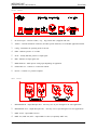
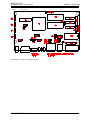
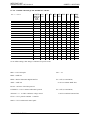
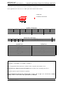
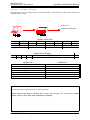
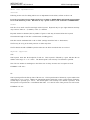
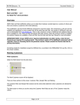
I/F 501
INTERFACE UNIT
INSTALLATION AND OPERATION GUIDE
Software Revision 1.05, Version A
INTRODUCTION
The I/F 501 interface unit allows a variety of comunication protocals used in NSI and other industrial equipment
to be translated between one another. In addition the I/F 501 can serve as an independent, programmable lighting
controller. The I/F 501 also serves as the interface between NSI’s Luma-net network and a personal computer.
SPECIFICATIONS:
Microplex Input (I/O)
3 pin XLR male
Microplex Ouput (I/O)
3 pin XLR female
DMX 512 Input
5 pin XLR male (USITT spec)
DMX 512 Output
5 pin XLR female (USITT spec)
AMX 192 Output (optional, replaces 512)
4 pin XLR female (USITT spec)
RS-232 I/O
9 pin ‘‘D’’ connector
MIDI input / Analog input
5 pin din 180 degree connector
Luma-net I/O
Modular style telephone connector
Power requirements
+15VDC 200ma (power supply included)
IMPORTANT
Although many different connectors are present on this unit, in most configurations, one or more of the connectors
may serve no function. It is important that the installer verify that the required inputs and outputs operated in the
mode required for the application. Please read the appropriate application sheets in this manual carefully before
installing.
INTERFACE UNIT
Software Revision 1.05, Version A
Front Panel
Front Panel
1
DC Power input - Connect 15VDC (+ tip, - ring) 250ma here. (Supplied with unit.)
2
Address - Controls translation of adresses (and other special functions). See individual applications details.
3
Config - Determines the operating mode of the unit.
4
PWR - Indicates presence of +15VDC
5
STAT - Usually indicates presence of input signal.
6
ERR - Indicates an input signal error.
7
MIDI/ANALOG - Midi input or analog input depending on application.
8
LUMA-NET I/O - Connects to a Luma-net network.
9
RS-232 - Connects to a personal computer.
Rear Panel
1
MICROPLEX IN - Input Microplex here. Also may serve as pass- through I/O in some applications.
2
MICROPLEX OUT - Output Microplex here. Also may serve as pass-through I/O in some applications.
3
DMX 512 IN - Input DMX 512 here.
4
DMX 512 (AMX 192) OUT - Output DMX 512 here (or optionally AMX 192).
NSI CORPORATION
2
INTERFACE UNIT
Software Revision 1.05, Version A
JUMPER
JUMPER LOCATIONS
LOCATIONS
PCB locations of jumpers / internal connectors
NSI CORPORATION
3
INTERFACE UNIT
Software Revision 1.05, Version A
JUMPER LOCATIONS
I/F 501 JUMPER CHANGE QUICK REFERENCE CHART
INPUT -> OUTPUT
DEFAULT SETTINGS
MPX -> DMX
MPX -> AMX
DMX -> MPX
MIDI -> MPX/DMX
MIDI -> AMX
RS-232 -> MPX/DMX
RS-232 -> AMX
LUMANET/MPX/DMX -> MPX
LUMANET/MPX -> DMX
LUMANET/MPX -> AMX
MPX/DMX/ANALOG -> MPX/DMX
MPX/DMX/ANALOG -> AMX
AUTO-CHASE -> MPX
RS-232 AUTO-CUEING -> MPX/DMX
IF-501 (AS 404CP) -> LUMANET
RS-232 -> LUMANET
CONFIG P4
P7 JP1
SWITCH P5
d-down
u-up
1234
dddd
OFF ON
6
dddd
uddd
OFF
dudd
ON
uudd
2
ddud
OFF
2
udud
duud
OFF
uuud
ON
2
dddu
2
uddu
OFF
2
dudu
uudu
OFF
dduu
uduu
duuu
uuuu
JP6
JP7
JP8 JP10 JP11 JP12 DMX
JP9
OUT
CONN
2-3
2-3
2-3
2-3
1-2
JP4
JP3
1-2
1-2
1-2
1-2
2-3
2-3
1-2
1-2
JP3
JP3
JP3
JP3
1-2
1-2
1-2
1-2
1-2
1-2
Set to default settings, then change as indicated for specific mode.
MPX = N.S.I. Microplex
JP13 = 2-3
DMX = DMX-512
MIDI = Musical Instrument Digital Interface
AMX = AMX-192
P6 = OFF (no termination)
or ON to terminate DMX lines
RS-232 = RS-232C Serial data protocol
LUMANET = N.S.I. Lumanet architectural protocol
ANALOG = 0 - 10 VDC continuous voltage control
P8 = OFF (no termination)
or ON to terminate Lumanet lines
IF-501 = N.S.I. protocol translator / controller
404CP = N.S.I. architectural control panel
NSI CORPORATION
4
INTERFACE UNIT
Software Revision 1.05, Version A
PINOUTS
PINOUTS
Pinouts of the various connectors
NSI CORPORATION
5
INTERFACE UNIT
Software Revision 1.05, Version A
MICROPLEX TO DMX 512
MICROPLEX TO DMX 512
In this application, Microplex is converted to DMX-512. The Microplex is then retransmitted.
P4 & 5
OPEN
P7
CLOSED
JP6 & 7
N/A
P6
N/A
C1
DN
C2
DN
C3
DN
C4
DN
JUMPER LOCATIONS
JP8 & 9
JP10
JP11
N/A
2-3
2-3
P8
JP1
N/A
N/A
JP12
JP13
N/A
2-3
DMX OUT CABLE
JP4
DIPSWITCH POSITIONS
ADDRESS 1 - 7
NOT USED
CONNECTOR
Microplex IN
Microplex OUT
DMX IN
DMX out
MIDI / Analog
Luma-net
RS-232
A8
DN:64
OPERATION
Input Microplex
Retransmitting Microplex (64 or 128)
Not used
Output DMX 512
Not used
Not Used
Not Used
Microplex is converted channel to channel so address is not used.
DMX output is sent as either 64 or 128 channels, depending on the setting of switch A8.
NSI CORPORATION
6
INTERFACE UNIT
Software Revision 1.05, Version A
MICROPLEX TO AMX 192
MICROPLEX TO AMX 192
In this application, Microplex is converted to AMX-192. The 5 pin XLR may be replaced with a 4 pin XLR
(USITT) if desired.
P4 & 5
OPEN
P7
OPEN
JP6 & 7
N/A
P6
N/A
C1
UP
C2
DN
C3
DN
C4
DN
CONNECTOR
Microplex IN
Microplex OUT
DMX IN
*DMX out
MIDI / Analog
Luma-net
RS-232
JUMPER LOCATIONS
JP8 & 9
JP10
JP11
N/A
2-3
2-3
P8
JP1
N/A
N/A
JP12
JP13
N/A
2-3
DMX OUT CABLE
JP3
DIPSWITCH POSITIONS
ADDRESS 1 - 7
N/A
A8
DN:64
OPERATION
Input Microplex
Not Used
Not used
Output AMX 192 (64 or 128 channels)
Not used
Not Used
Not Used
Microplex is converted channel to channel so address is not used.
AMX output is sent as either 64 or 128 channels, depending on the setting of switch A8.
*IMPORTANT - Move AMX output connector jumper from JP4 to JP3.
NSI CORPORATION
7
INTERFACE UNIT
Software Revision 1.05, Version A
DMX 512 TO MICROPLEX
DMX 512 TO MICROPLEX
In this application, DMX 512 is converted to Microplex..
P4 & 5
CLOSED
P7
CLOSED
JP6 & 7
N/A
P6
*CLOSE TO TERM
DMX
C1
DN
C2
UP
C3
DN
C4
DN
JUMPER LOCATIONS
JP8 & 9
JP10
JP11
N/A
2-3
2-3
P8
JP1
N/A
N/A
JP12
JP13
N/A
2-3
DMX OUT CABLE
JP4
DIPSWITCH POSITIONS
ADDRESS 1 - 7
A8
STARTING DMX CHANNEL FOR MICROPLEX BY 16 INCR. DN:64
CONNECTOR
Microplex IN
Microplex OUT
DMX IN
DMX out
MIDI / Analog
Luma-net
RS-232
OPERATION
Not used
Output Microplex (64 or 128)
Input DMX 512
Pass through DMX 512
Not used
Not Used
Not Used
Microplex channel 1 is equal to starting DMX channel. Address switch 1 - 6 sets starting DMX channel in
increments of 16. See chart at the end of this manual.
Microplex output is sent as either 64 or 128 channels, depending on the setting of switch A8.
*DMX should only be terminated internally if IF501 will be always last unit at end of DMX line. A better way
to terminate is to connect 120ohm resistor to a female DMX cable end (pins 2-3) and plug it into the pass-through
of the last unit on the DMX line.
NSI CORPORATION
8
INTERFACE UNIT
Software Revision 1.05, Version A
MIDI TO MICROPLEX and DMX 512
MIDI TO MICROPLEX and DMX 512
In this application, MIDI note commands are converted to Microplex and DMX 512 dimmer levels.
P4 & 5
OPEN
P7
CLOSED
JP6 & 7
N/A
P6
N/A
C1
UP
C2
UP
C3
DN
C4
DN
JUMPER LOCATIONS
JP8 & 9
JP10
JP11
1-2
1-2
2-3
P8
JP1
N/A
POSITION 2
JP12
JP13
2-3
2-3
DMX OUT CABLE
JP4
DIPSWITCH POSITIONS
ADDRESS 1 - 7
A1-4 SELECTS MIDI CHAN, 5 UP SETS IGNORE NTOFF
CONNECTOR
Microplex IN
Microplex OUT
DMX IN
DMX out
MIDI / Analog
Luma-net
RS-232
A8
DN:64
OPERATION
Not Used
Output Microplex (64 or 128)
Not Used
Output DMX 512
Input MIDI
Not Used
Not Used
MIDI Channel 1 - 16 can be selected with switch A1-4 (see chart at end).
Velocity of MIDI Note On messages set respective dimmer levels. C0 = dimmer channel 1.
Note Off (or Note On = 0) will turn off channel unless A5 is in the up position.
DMX or Microplex output is sent as either 64 or 128 channels, depending on the setting of switch A8.
NSI CORPORATION
9
INTERFACE UNIT
Software Revision 1.05, Version A
MIDI TO AMX-192
MIDI TO AMX-192
In this application, MIDI is converted to AMX 192.
P4 & 5
OPEN
P7
OPEN
P6
N/A
C1
DN
C2
DN
C3
UP
JUMPER LOCATIONS
JP6 & 7
JP8 & 9
JP10
JP11
N/A
1-2
1-2
2-3
P8
JP1
N/A
POSITION 2
C4
DN
JP12
JP13
2-3
2-3
DMX OUT CABLE
JP3
DIPSWITCH POSITIONS
ADDRESS 1 - 7
A1-4 SELECTS MIDI CHAN, A5 UP SETS IGNORE NTOFF
CONNECTOR
Microplex IN
Microplex OUT
DMX IN
*DMX out
MIDI / Analog
Luma-net
RS-232
A8
DN:64
OPERATION
Not used
Not Used
Not used
Output AMX 192 (64 or 128 ch)
MIDI Input
Not Used
Not Used
MIDI Channel 1 - 16 can be selected with switch A1-4 (see chart at end).
Velocity of MIDI Note On messages set respective dimmer levels. C0 = dimmer channel 1.
Note Off (or Note On = 0) will turn off channel unless A5 is in the up position.
AMX output is sent as either 64 or 128 channels, depending on the setting of switch A8.
*IMPORTANT - Move AMX output connector jumper from JP4 to JP3.
NSI CORPORATION
10
INTERFACE UNIT
Software Revision 1.05, Version A
RS-232 to MICROPLEX and DMX 512
RS-232 to MICROPLEX and DMX 512
In this application, a computer may send simple ASCII commands to operate individual dimmer channels.
P4 & 5
OPEN
P7
CLOSED
JP6 & 7
1-2
P6
N/A
C1
UP
C2
DN
C3
UP
C4
DN
CONNECTOR
Microplex IN
Microplex OUT
DMX IN
DMX out
MIDI / Analog
Luma-net
RS-232
JUMPER LOCATIONS
JP8 & 9
JP10
JP11
N/A
2-3
2-3
P8
JP1
N/A
POS 5 OR 6 (BELOW)
JP12
JP13
1-2
2-3
DMX OUT CABLE
JP4
DIPSWITCH POSITIONS
ADDRESS 1 - 7
N/A
A8
DN:64
OPERATION
Not Used
Output Microplex (64 or 128)
Not used
Output DMX 512 (64 or 128)
Not used
Not Used
RS-232 Input
Baudrate is either 9600 (JP1 - 6) or 2400 (JP1 - 5) with 8 data bits, 1 stop bit, no parity
Dimmer channels 1 to 100 can be controlled with these simple ASCII commands:
ASCII characters supported: F D G R - @ + : . 0-9
Fxx:xx.x (FADERATE, x=fade time in minutes : seconds . tenths),
Dccc-ccc@xxx (DIMMER LEVEL, c=channel number, -=to, +=and, x= level)
G (EXECUTE) R (RESET or BLACKOUT)
Carriage return after each command. Max fade time is 50 minutes.
DMX and Microplex output is sent as either 64 or 128 channels, depending on the setting of switch A8.
NSI CORPORATION
11
INTERFACE UNIT
Software Revision 1.05, Version A
RS-232 TO AMX 192
RS-232 TO AMX 192
In this application, a personal computer may send ascii commands to operate individual dimmer channels.
P4 & 5
OPEN
P7
OPEN
JP6 & 7
1-2
P6
N/A
C1
DN
C2
UP
C3
UP
C4
DN
CONNECTOR
Microplex IN
Microplex OUT
DMX IN
*DMX out
MIDI / Analog
Luma-net
RS-232
JUMPER LOCATIONS
JP8 & 9
JP10
JP11
N/A
2-3
2-3
P8
JP1
N/A
POS 5 OR 6 (BELOW)
JP12
JP13
1-2
2-3
DMX OUT CABLE
JP3
DIPSWITCH POSITIONS
ADDRESS 1 - 7
N/A
A8
DN:64
OPERATION
Not Used
Not Used
Not used
Output AMX 192 (64 or 128)
Not used
Not Used
Input RS-232
Baudrate is either 9600 (JP1 - 6) or 2400 (JP1 - 5) with 8 data bits, 1 stop bit, no parity
Dimmer channels 1 to 100 can be controlled with these simple ASCII commands:
ASCII characters supported: F D G R - @ + : . 0-9
Fxx:xx.x (FADERATE, x=fade time in minutes : seconds . tenths),
Dccc-ccc@xxx (DIMMER LEVEL, c=channel number, -=to, +=and, x= level)
G (EXECUTE) R (RESET or BLACKOUT)
Carriage return after each command. Max fade time is 50 minutes.
Max fade time is 50 minutes.
AMX output is sent as either 64 or 128 channels, depending on the setting of switch A8.
*IMPORTANT - Move AMX output connector jumper from JP4 to JP3.
NSI CORPORATION
12
INTERFACE UNIT
Software Revision 1.05, Version A
LUMA-NET to MICROPLEX
LUMA-NET to MICROPLEX
In this application, Microplex or DMX is mixed with LUMA-NET and transmitted as Microplex.
P4 & 5
CLOSED
P7
CLOSED
JUMPER LOCATIONS
JP8 & 9
JP10
JP11
N/A
2-3
2-3
P8
JP1
CLOSE TO TERM
POSITION 2
LUMA
JP6 & 7
2-3
P6
*CLOSE TO TERM
DMX
C1
UP
C2
UP
C3
UP
C4
DN
CONNECTOR
Microplex IN
Microplex OUT
DMX IN
DMX out
MIDI / Analog
Luma-net
RS-232
JP12
JP13
1-2
2-3
DMX OUT CABLE
JP4
DIPSWITCH POSITIONS
ADDRESS 1 - 7
STARTING ADDR OF LUMA-NET IN 16 INCREMENT
A8
DN:64
OPERATION
Input Microplex
Retransmitting Microplex (64 or 128)
Input DMX 512
Pass through DMX-512
Not used
Luma-net network
Not Used
Allows 128 channels of Luma-net to be merged with microplex in a ‘‘last action takes precedence’’ fashion.
Terminate DMX or Luma-net by closing jumper P6 or P8 only if last device on line.
*DMX should only be terminated internally if IF501 will be always last unit at end of DMX line. A better way
to terminate is to connect 120ohm resistor to a female DMX cable end (pins 2-3) and plug it into the pass-through
of the last unit on the DMX line.
See operator’s manual of Luma-net device for additonal information.
Microplex output is sent as either 64 or 128 channels, depending on the setting of switch A8.
NSI CORPORATION
13
INTERFACE UNIT
Software Revision 1.05, Version A
LUMA-NET to DMX-512
LUMA-NET to DMX-512
In this application, Microplex or DMX is mixed with LUMA-NET and transmitted as DMX 512.
P4 & 5
OPEN
P7
N/A
JUMPER LOCATIONS
JP8 & 9
JP10
JP11
N/A
2-3
2-3
P8
JP1
CLOSE TO TERM
POSITION 2
LUMA
JP6 & 7
2-3
P6
CLOSE
C1
DN
C2
DN
C3
DN
C4
UP
JP12
JP13
1-2
2-3
DMX OUT CABLE
JP4
DIPSWITCH POSITIONS
ADDRESS 1 - 7
STARTING ADDR OF LUMA-NET IN 16 INCREMENT
CONNECTOR
Microplex IN
Microplex OUT
DMX IN
DMX out
MIDI / Analog
Luma-net
RS-232
A8
OPERATION
Input Microplex
Not Used
Input DMX 512
Output new DMX-512
Not used
Luma-net network
Not Used
Allows 128 channels of Luma-net to be merged with DMX 512 in a ‘‘last action takes precedence’’ fashion.
Terminate Luma-net by closing jumper P8 only if last device on line.
Input of IF 501 is always last device at end of source DMX line.
See operator’s manual of Luma-net device for additional information.
DMX output is sent as either 64 or 128 channels, depending on the setting of switch A8.
NSI CORPORATION
14
INTERFACE UNIT
Software Revision 1.05, Version A
LUMA-NET to AMX - 192
LUMA-NET to AMX - 192
In this application, Microplex or DMX is mixed with LUMA-NET and transmitted as AMX-192.
P4 & 5
OPEN
P7
OPEN
P6
CLOSE
C1
UP
C2
DN
C3
DN
JUMPER LOCATIONS
JP8 & 9
JP10
JP11
N/A
2-3
2-3
P8
JP1
CLS TO TERM LUMA
POS 2
JP6 & 7
2-3
C4
UP
JP12
JP13
1-2
2-3
DMX OUT CABLE
JP3
DIPSWITCH POSITIONS
ADDRESS 1 - 7
STARTING ADDR OF LUMA-NET IN 16 INCREMENT
CONNECTOR
Microplex IN
Microplex OUT
DMX IN
*DMX out
MIDI / Analog
Luma-net
RS-232
A8
DN:64
OPERATION
Input Microplex
Not Used
Input DMX 512
Output AMX-192
Not used
Luma-net network
Not Used
Allows up to 128 channels of Luma-net to be merged with DMX or Microplex and output as AMX 192 in a ‘‘last
action takes precedence’’ fashion.
Terminate Luma-net by closing jumper P8 only if last device on line.
IF 501 is always last device at end of DMX line.
See operator’s manual of Luma-net device for additonal information.
AMX output is sent as either 64 or 128 channels, depending on the setting of switch A8.
*IMPORTANT - Move AMX output connector jumper from JP4 to JP3.
NSI CORPORATION
15
INTERFACE UNIT
Software Revision 1.05, Version A
ANALOG
ANALOG TO / MERGED WITH DMX 512 and MICROPLEX
TO / MERGED WITH DMX 512 and MICROPLEX
In this application, 0 to 10VDC is converted to Microplex or and DMX 512..
P4 & 5
OPEN
P7
CLOSED
JP6 & 7
N/A
P6
*CLOSE TO TERM
DMX
C1
DN
C2
UP
C3
DN
C4
UP
JUMPER LOCATIONS
JP8 & 9
JP10
JP11
2-3
2-3
2-3
P8
JP1
N/A
N/A
JP12
JP13
N/A
2-3
DMX OUT CABLE
JP4
DIPSWITCH POSITIONS
ADDRESS 1 - 7
A8
STARTING ADDR OF ANALOG CHAN 1 BY 1 INCREMENT DN:64
CONNECTOR
Microplex IN
Microplex OUT
DMX IN
DMX out
MIDI / Analog
Luma-net
RS-232
OPERATION
Input Microplex
Output Microplex (64 or 128)
Input DMX 512
Output new DMX 512
0-10VDC input
Not Used
Not Used
Four analog 0-10V channels are merged with DMX-512 or Microplex and output as DMX-512 and Microplex.
Channel number of first analog channel is determined by A1-7.
DMX and Microplex output is sent as either 64 or 128 channels, depending on the setting of switch A8.
*Close P6 if inputting DMX. IF 501 is always last device at end of DMX line.
NSI CORPORATION
16
INTERFACE UNIT
Software Revision 1.05, Version A
ANALOG
ANALOG TO AMX-192
TO AMX-192
In this application, 0 - 10VDC is converted to AMX 192.
P4 & 5
OPEN
P7
OPEN
JP6 & 7
N/A
P6
*CLOSE TO TERM
DMX
C1
UP
C2
UP
C3
DN
C4
UP
JUMPER LOCATIONS
JP8 & 9
JP10
JP11
2-3
2-3
2-3
P8
JP1
N/A
N/A
JP12
JP13
N/A
2-3
DMX OUT CABLE
JP3
DIPSWITCH POSITIONS
ADDRESS 1 - 7
STARTING ADDR OF ANALOG CHAN 1 BY 1 INCREMENT
CONNECTOR
Microplex IN
Microplex OUT
DMX IN
**DMX out
MIDI / Analog
Luma-net
RS-232
A8
OPERATION
Input Microplex
Not Used
Input DMX 512
Output AMX 192
0-10VDC input
Not Used
Not Used
Four analog 0-10V channels are merged with DMX-512 or Microplex and output as AMX-192.
Channel number of first analog channel is determined by A1-7.
AMX output is sent as either 64 or 128 channels, depending on the setting of switch A8.
*Close P6 if inputting DMX. IF 501 is always last device at end of DMX line.
**IMPORTANT - Move AMX output connector jumper from JP4 to JP3.
NSI CORPORATION
17
INTERFACE UNIT
Software Revision 1.05, Version A
AUTOCHASE TO MICROPLEX AND DMX 512.
AUTOCHASE TO MICROPLEX AND DMX 512.
In this application, the unit serves as a stand alone chaser.
P4 & 5
N/A
P7
CLOSED
JP6 & 7
N/A
P6
N/A
C1
DN
C2
DN
C3
UP
C4
UP
CONNECTOR
Microplex IN
Microplex OUT
DMX IN
DMX out
MIDI / Analog
Luma-net
RS-232
JUMPER LOCATIONS
JP8 & 9
JP10
JP11
N/A
2-3
2-3
P8
JP1
N/A
N/A
JP12
JP13
N/A
2-3
DMX OUT CABLE
JP4
DIPSWITCH POSITIONS
ADDRESS 1 - 7
SETS CHASE PATTERN AND SPEED
A8
DN:64
OPERATION
Not Used
Output Microplex (64 or 128)
Not Used
Output DMX 512 (64 or 128)
Not Used
Not Used
Not Used
See chase speed and pattern chart at then end of the guide for settings of A1-7.
DMX and Microplex output is sent as either 64 or 128 channels, depending on the setting of switch A8.
NSI CORPORATION
18
INTERFACE UNIT
Software Revision 1.05, Version A
RS-232
RS-232 AUTO-CUEING TO MICROPLEX AND DMX.
AUTO-CUEING TO MICROPLEX AND DMX.
In this application, the unit serves as a stand alone programmable memory lighting controller with precise timed
crossfading. Optionally contact closures serve for manual control.
P4 & 5
N/A
P7
CLOSED
JP6 & 7
1-2
P6
N/A
C1
UP
C2
DN
C3
UP
C4
UP
JUMPER LOCATIONS
JP8 & 9
JP10
JP11
2-3
2-3
1-2
P8
JP1
N/A
SETS BAUD RATE
JP12
JP13
1-2
2-3
DMX OUT CABLE
JP4
DIPSWITCH POSITIONS
ADDRESS 1 - 7
N/A
CONNECTOR
Microplex IN
Microplex OUT
DMX IN
DMX out
MIDI / Analog
Luma-net
RS-232
A8
N/A
OPERATION
Not Used
Output Microplex (16 channels)
Not Used
Output DMX 512 (16 channels)
Contact Closures
Not Used
Personal Computer or Melange (for
programming).
Use analog input for optional contact closures:
1-2 STOP NOW, 4-2 STOP AT END OF CHAIN, 5-2 REWIND AND B/O, 3-2 STOP AT END OF CUE.
Only the first 16 channels are sent. 20 ASCII cues max. can be down loaded via the RS-232 port of a PC or
Melange.
Cue numbers are ignored, cues execute in the order they are down loaded.
Baudrate = 9600 baud (JP1 pos 6) or 2400 baud (JP1 pos 5), 8 bits, no parity, 1 stop bit, DTR-DSR handshake.
See chart at end of guide for ASCII CUE systax accepted.
NSI CORPORATION
19
INTERFACE UNIT
Software Revision 1.05, Version A
LUMA-NET 404CP EMULATION WITH EXTERNAL CONTACTS.
LUMA-NET 404CP EMULATION WITH EXTERNAL CONTACTS.
In this application, the unit serves as a 404CP panel with external contact closures.
LUMA-NET
LIGHTING NETWORK
P4 & 5
OPEN
P7
N/A
P6
N/A
C1
DN
C2
UP
C3
UP
JUMPER LOCATIONS
JP8 & 9
JP10
JP11
2-3
2-3
1-2
P8
JP1
CLS TO TERM LUMA
N/A
JP6 & 7
1-2
C4
UP
JP12
JP13
N/A
2-3
DMX OUT CABLE
JP4
DIPSWITCH POSITIONS
ADDRESS 1 - 8
LUMANET NETWORK ID
CONNECTOR
Microplex IN
Microplex OUT
DMX IN
DMX out
MIDI / Analog
Luma-net
RS-232
OPERATION
Not Used
Not Used
Not Used
Not Used
Contact Closures
Luma-net Network
Not Used
Use analog input for contact closures:
1-2 SCENE 1, 4-2 SCENE 2, 5-2 SCENE 3, SCENE 4.
Must be programmed from Luma-net PC Software and in conjuction with another IF 501.
IF-501 must has a different Network ID number than any other device (including other 501’s).
See 404CP operator’s guide for details on operation.
Caution Lumanet IF cable must be connected pin 1 to pin 1, pin 2 to pin 2, ect. Do not use a standard
telephone cable to connect units unless polarization is confirmed.
NSI CORPORATION
20
INTERFACE UNIT
Software Revision 1.05, Version A
LUMA-NET
LUMA-NET SOFTWARE INTERFACE.
SOFTWARE INTERFACE.
This application is for use with the Luma-net Computer Software. This unit serves as the interface between the
computer and the network.
LUMA-NET
LIGHTING NETWORK
P4 & 5
OPEN
P7
N/A
P6
N/A
C1
UP
C2
UP
C3
UP
JUMPER LOCATIONS
JP8 & 9
JP10
JP11
N/A
2-3
1-2
P8
JP1
CLS TO TERM LUMA
BAUD RATE
JP6 & 7
1-2
C4
UP
JP12
JP13
1-2
2-3
DMX OUT CABLE
JP4
DIPSWITCH POSITIONS
ADDRESS 1 - 8
NETWORK ID
CONNECTOR
Microplex IN
Microplex OUT
DMX IN
DMX out
MIDI / Analog
Luma-net
RS-232
OPERATION
Not Used
Not Used
Not Used
Not Used
Not Used
Luma-net Network
Personal Computer
Baudrate = 9600 baud (JP1 pos 6) or 2400 baud (JP1 pos 5), 8 bits, no parity, 1 stop bit, DTR-DSR handshake.
See Luma-net Software Operation Guide for more information.
Caution: Lumanet cable must be connected pin 1 to pin 1, pin 2 to pin 2, ect. Do not use a standard
telephone cable to connect units unless polarization is confirmed.
NSI CORPORATION
21
INTERFACE UNIT
Software Revision 1.05, Version A
Lumanet Channel number codes / dipswitch settings.
Lumanet Channel number codes / dipswitch settings.
Multiply channel listed by increment required. Subtract one for Luma-net network ID no.
0 - switch down, 1 - switch up.
Lumanet
Channel
1
2
3
4
5
6
7
8
9
10
11
12
13
14
15
16
17
18
19
20
21
22
23
24
25
26
27
28
29
30
31
32
Dipswitch
1234567
0000000
1000000
0100000
1100000
0010000
1010000
0110000
1110000
0001000
1001000
0101000
1101000
0011000
1011000
011100
1111000
0000100
1000100
0100100
1100100
0010100
1010100
0110100
1110100
0001100
1001100
0101100
1101100
0011100
1011100
0111100
1111100
NSI CORPORATION
Lumanet
Channel
33
34
35
36
37
38
39
40
41
42
43
44
45
46
47
48
49
50
51
52
53
54
55
56
57
58
59
60
61
62
63
64
Dipswitch
1234567
0000010
1000010
0100010
1100010
0010010
1010010
0110010
1110010
0001010
1001010
0101010
1101010
0011010
1011010
0111010
1111010
0000110
1000110
0100110
1100110
0010110
1010110
0110110
1110110
0001110
1001110
0101110
1101110
0011110
1011110
0111110
1111110
Lumanet
Channel
65
66
67
68
69
70
71
72
73
74
75
76
77
78
79
80
81
82
83
84
85
86
87
88
89
90
91
92
93
94
95
96
Dipswitch
1234567
0000001
1000001
0100001
1100001
0010001
1010001
0110001
1110001
0001001
1001001
0101001
1101001
0011001
1011001
0111001
1111001
0000101
1000101
0100101
1100101
0010101
1010101
0110101
1110101
0001101
1001101
0101101
1101101
0011101
1011101
0111101
1111101
Lumanet
Channel
97
98
99
100
101
102
103
104
105
106
107
108
109
110
111
112
113
114
115
116
117
118
119
120
121
122
123
124
125
126
127
128
Dipswitch
1234567
0000011
1000011
0100011
1100011
0010011
1010011
0110011
1110011
0001011
1001011
0101011
1101011
0011011
1011011
0111011
1111011
0000111
1000111
0100111
1100111
0010111
1010111
0110111
1110111
0001111
1001111
0101111
1101111
0011111
1011111
0111111
1111111
22
INTERFACE UNIT
Software Revision 1.05, Version A
DMX 512 Channel number codes / dipswitch settings.
DMX 512 Channel number codes / dipswitch settings.
0 - switch down, 1 - switch up
1st DMX
Channel
1
17
33
49
65
81
97
113
Dipswitch
1234567
0000000
1000000
0100000
1100000
0010000
1010000
0110000
1110000
NSI CORPORATION
1st DMX
Channel
129
145
161
177
193
209
225
241
Dipswitch
1234567
0001000
1001000
0101000
1101000
0011000
1011000
0111000
1111000
1st DMX
Channel
257
273
289
305
321
337
353
369
Dipswitch
1234567
0000100
1000100
0100100
1100100
0010100
1010100
0110100
1110100
1st DMX
Channel
385
401
417
433
449
465
481
497
Dipswitch
1234567
0001100
1001100
0101100
1101100
0011100
1011100
0111100
1111100
23
INTERFACE UNIT
Software Revision 1.05, Version A
ASCII Cues Implementation
ASCII Cues Implementation
Overview
Following are the rules for editing ASCII Cues as implemented on the IF501, software revision 1.00:
If you use a word processor for editing ASCII Cues you must set WORD WRAP OFF and the margin should
be set to 80 characters per line. DO NOT use any ‘‘special’’ features; such as BOLD or UNDERLINING.
Format
Each line of an ASCII Cues file must begin with a keyword. Keywords may be up to eight characters and may
only consist of letters A - Z, numbers, or the ‘‘$’’ character.
Keywords cannot be shortened, but any number of spaces or tabs may be inserted before the keyword.
The maximum length of each line is 80 characters (including spaces).
Each line must be terminated with a CR or CR/LF (carriage return/line feed or ‘‘hard return’’).
The file may be as big as the word processor or editor may allow.
The file should end with a $END keyword to make sure the IF501 records the last cue received.
Keywords Supported.
CUE
This keyword must start the description of each cue. This keyword is followed by a space and then the cue
number in the range of ‘‘.1" to ’’999.9". The decimal point is not necessary if no decimal is specified.
Note: The Cue number is meaningless to the IF501 since it always executes cues in sequence received.
EXAMPLE: CUE 238.5
UP
This keyword specifies the fade up time of the new cue. This keyword must be followed by a space and the time
in the range of ‘‘0" to ’’9:59.9". Minutes are optional but must be followed by a colon. In the absence of minutes,
seconds may be specified up to ‘‘999.9". The decimal point is not necessary if no decimal is specified. If the
UP keyword is not specified in a cue definition then either ’’0" or the UP value of the previous cue will be used.
EXAMPLE: UP 10.5
NSI CORPORATION
24
INTERFACE UNIT
Software Revision 1.05, Version A
Keywords Supported.
DOWN
This keyword specifies the fade down time of the previous cue. This keyword must be followed by a space and
the time in the range of ‘‘0" to ’’9:59.9". Minutes are optional but must be followed by a colon. In the absence
of minutes, seconds may be specified up to ‘‘999.9". The decimal point is not necessary if no decimal is specified.
If the DOWN keyword is not specified in a cue definition then either ’’0" or the DOWN value of the previous
cue will be used.
EXAMPLE: DOWN 1:30
DELAY
This keyword specifies the time delay before the downfade of the previous cue. This keyword must be followed
by a space and the time in the range of ‘‘0" to ’’9:59.9". Minutes are optional but must be followed by a colon.
In the absence of minutes, seconds may be specified up to ‘‘999.9". The decimal point is not necessary if no
decimal is specified. If the DELAY keyword is not specified in a cue definition then either ’’0" or the DELAY
value of the previous cue will be used.
EXAMPLE: DELAY 30
WAIT
This keyword specifies the time delay before the execution of a linked cue. This keyword must be followed by
a space and the time in the range of ‘‘0" to ’’9:59.9". Minutes are optional but must be followed by a colon. In
the absence of minutes, seconds may be specified up to ‘‘999.9". The decimal point is not necessary if no decimal
is specified. If the WAIT keyword is not specified in a cue definition then a automatic link will not be performed,
and the GO button must be pressed to execute the cue specified.
EXAMPLE: WAIT 1.1
CHANNEL
This keyword is used to specify the channel levels (in percent) of each non-zero channel of the cue. This keyword
must be followed by a space and the channel levels in the format of ‘‘channel,level’’. As many channel/level pairs
may be included on a line as will fit. Each channel/level pair must be separated by a space. Each additional line
specifying channel levels must also begin with the keyword. Full level is represented by ‘‘100" ,’’FF", or ‘‘FL’’.
Any channel not specified will be zero.
EXAMPLE: CHANNELS 1,50 20,25 21,25 22,100
NSI CORPORATION
25
INTERFACE UNIT
Software Revision 1.05, Version A
NSI Corporation Limited Warranty
WARRANTY
NSI Corporation Limited Warranty
NSI Corporation warrants new electronics products to be free from defective materials and workmanship for a
period of one (1) year from the date of purchase to the original owner when purchased from an authorized NSI
dealer.
The purchaser is responsible for completing and mailing to NSI, within 15 days of purchase, the warranty registration
card enclosed with each product. NSI products that have been subject to accident, alteration, abuse, or defacing
of the serial number are not covered by this warranty. The normal wear and tear of items such as knobs, jacks,
and switches are not covered under this warranty.
If your NSI product requires service during the warranty period, NSI will repair or replace, at its option, defective
materials provided you have identified yourself as the original owner of the product to NSI or any authorized NSI
dealer. Transportation charges to and from an authorized dealer or the NSI factory for repair shall be the responsibility
of the owner. All products returned to NSI must have factory authorization for return prior to shipping.
NSI Corporation is not liable for any incidental or consequential damages resulting from defect or failure other
than repairs of the NSI product subject to the terms of this warranty. This warranty gives you specific legal rights,
and you may have other rights which vary from state to state. This warranty is expressly in lieu of all other
agreements and warranties expressed or implied except as may be otherwise required by law.
NSI CORPORATION
26