1
BAR CODE MANUAL
ICR 803
Bar Code Scanner
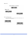
Using This Manual
This manual contains bar codes used to program the ICR803.
For initial setup, product identification, and general product information, please refer to
the following manuals:
ICR803 Quick Start Manual
ICR803 Command & Communication Guide
Plug and Play Bar Codes
Plug and Play bar codes provide instant engine set up for commonly used interfaces. Please note
that the ICR803 interfaces are configured by the factory at time of order. These bar codes are
therefore used to default the scanner to get back to the factory setup.
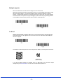
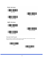
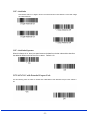
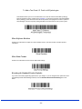
RS-232
The RS-232 Interface bar code is used when connecting to the serial port of a PC or terminal. The
following RS-232 Interface bar code also programs a carriage return (CR) and a line feed (LF)
suffix, baud rate, and data format as indicated below:
Option Setting
Baud Rate 115200 bps
Data Format 8 data bits, no parity bit, 1 stop bit
RS-232 Interface
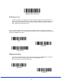
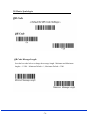
USB HID
Scan the following code to default the USB version of the ICR803 for USB HID bar code
imagers. Scanning this code changes the terminal ID to 131.
USB HID Bar Code Imager
ICR803 Bar Code Manual – Rev A – 04/2007
-2-
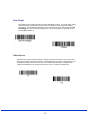
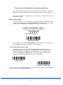
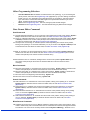
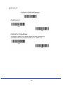
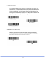
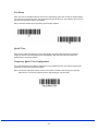
USB COM Port Emulation
Scan the following code to program the USB version of the ICR803 to emulate a regular RS-232 based
COM port. If you are using Microsoft Windows, you will need to install the USB Driver for the scanner.
ICR803 Bar Code Manual – Rev A – 04/2007
-3-
ICR803 Bar Code Manual – Rev A – 04/2007
-4-
ICR803 Bar Code Manual – Rev A – 04/2007
-5-
ICR803 Bar Code Manual – Rev A – 04/2007
-6-
Good Read Indicators
ICR803 Bar Code Manual – Rev A – 04/2007
-7-
.
ICR803 Bar Code Manual – Rev A – 04/2007
-8-
Reread Delay
This sets the minimum amount of time before the imager can read the same bar code a second time.
Setting a reread delay protects against accidental rereads of the same bar code. Longer delays are
effective in minimizing rereads in POS (Point Of Sale) applications. Use shorter delays for applications
where repetitive scanning is required. (Default = Medium)
ICR803 Bar Code Manual – Rev A – 04/2007
-9-
User-Specified Good Read Delay
If you want to set your own length for the good read delay, scan the bar code below, then set the delay (from
0-30,000 milliseconds) by scanning digits from Appendix D, then scanning Save.
Trigger Modes
Manual/Serial Trigger
You can activate the imager either by providing an external hardware trigger, or using a serial
trigger command. When in manual trigger mode, the imager scans until a bar code is read, or until
the hardware trigger is released.
When in serial mode, the imager scans until a bar code has been read or until the deactivate
command is sent. In serial mode, the imager can also be set to turn itself off after a specified time
has elapsed (see Read Time Out, which follows).
Read Time Out
Use this selection to set a time out (in milliseconds) of the imager’s trigger when using serial
commands to trigger the imager, or if the imager is in manual trigger mode. Once the imager has
timed out, you can activate the imager either by pressing the trigger or using a serial trigger
command. After scanning the Read Time Out bar code, set the time out duration (from 0-300,000
milliseconds) by scanning digits from Appendix D, then scanning Save. Default = 0 (infinite, or no
time out).
ICR803 Bar Code Manual – Rev A – 04/2007
- 10 -
Manual Trigger, Low Power
The imager powers down until the trigger is pulled. When the trigger is pulled, the imager powers
up and operates until there is no triggering for the time set with the Low Power Time Out bar code
below. There is a delay of up to one second in operation when the imager is first triggered, but
there is no delay when operating in low power timeout mode.
Low Power Time Out Timer
Scan the Low Power Time Out bar code to change the time out duration (in seconds). Then scan
the time out duration (from 0-300 seconds) from Appendix D, and Save. Default = 120 seconds.
If the unit remains idle during the low power time out interval, the unit goes into low power mode.
Whenever the trigger is enabled, the low power time out timer is reset.
Note: This timeout does not begin until the imager timeout setting has expired.
Scan Stand Mode
When a unit is in Scan Stand mode, it remains idle as long as it sees the Scan Stand symbol. (See
Scan Stand Symbol that follows.) When a different code is presented, the Imager is triggered to
read the new code.
Note:The imager automatically adjusts the illumination LEDs to the lowest light level possible to
maintain a good lock on the Scan Stand symbol. When a symbol is presented, the imager’s light
levels adjust to the saved LED power setting.
Scan Stand Symbol
When a unit is in Scan Stand mode, the LEDs shine at the Scan Stand symbol on the base of the
stand which tells it to remain idle. When the Scan Stand symbol is covered, the imager turns the
LEDs on at the configured power level (Default High) and attempts to find and decode bar codes in
its field of view.
ICR803 Bar Code Manual – Rev A – 04/2007
- 11 -
Presentation Mode
This programs the imager to work in Presentation mode. The LEDs are either off or at the lowest power for
ambient conditions until a bar code is presented to the imager. Then the LEDs turn on automatically to read
the code. Presentation Mode uses ambient light to detect the bar codes. If the light level in the room is not
high enough, Presentation Mode may not work properly.
Presentation LED Behavior after Decode
When an imager is in presentation mode, the LEDs remain on and continue scanning for a short time after a
bar code is decoded. If you wish to turn the LEDs off immediately after a bar code is decoded, scan the
LEDs Off bar code, below. Default = LEDs On.
* LEDs On
LEDs Off
Presentation Sensitivity
Presentation Sensitivity is a numeric range that increases or decreases the imager's reaction time to bar
code presentation. To set the sensitivity, scan the Sensitivity bar code, then scan the degree of sensitivity
(from 0-20) from the inside back cover, and Save. 0 is the most sensitive setting, and 20 is the least
sensitive. Default = 1.
Sensitivity
Hands Free Time Out
The Scan Stand and Presentation Modes are referred to as “hands free” modes. If the imager’s
trigger is pulled when using a hands free mode, the imager changes to manual trigger mode. You
can set the time the imager should remain in manual trigger mode by setting the Hands Free Time
Out. Once the time out value is reached, (if there have been no further trigger pulls) the imager
reverts to the original hands free mode.
Scan the Hands Free Time Out bar code, then scan the time out duration (from 0-300,000
milliseconds) from Appendix D, and Save. Default = 5,000 ms.
ICR803 Bar Code Manual – Rev A – 04/2007
- 12 -
LED Power Level
This selection allows you to adjust LED and aimer brightness. Off is used when no illumination is
needed. Low is used if low illumination is sufficient. High (the default) is the brightest setting. If you
have an aimer delay programmed (see Aimer Delay), the aimer will be at 100% power during the
delay, regardless of the LED Power Level.
Note: If you scan the Off bar code, both the aimer and illumination lights turn off, making it impossible to
scan bar codes in low light. To turn the LED Power Level back on, move to a brightly lit area and scan either
the Low or the High bar code below.
Illumination Lights
If you want the illumination lights on while reading a bar code, scan the Lights On bar code, below.
However, if you want to turn just the lights off, scan the Lights Off bar code.
Note: This setting does not affect the aimer light.
- 13 -
Imager Time Out
Imager Time Out powers down the imager after the unit has been idle for the specified time. To
prevent the imager from powering down, set this time out to 0. Scan the bar code below, then set
the time out by scanning digits (from 0 - 999,999 ms) from Appendix D, then scanning Save.
Aimer Delay
The aimer delay allows a delay time for the operator to aim the imager before the picture is taken.
Use these codes to set the time between when the trigger is pulled and when the picture is taken.
During the delay time, the aiming light will appear, but the LEDs won’t turn on until the delay time is
over.
Aimer Mode
This feature allows you to lower peak current during scanning by alternating the aimer and
illumination LEDs. When the Interlaced bar code is scanned, the aimer and illumination LEDs are
not allowed to be on at the same time. While this does limit peak current during scanning, the
scanner performance may be slower. When the Concurrent bar code is scanned, the aimer and
illumination LEDs are allowed to light at the same time. Select Off if you don’t want to use either
aimer mode.
- 14 -
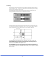
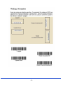
Centering
Use Centering to narrow the imager’s field of view to make sure the imager reads only those bar
codes intended by the user. For instance, if multiple codes are placed closely together, centering
will insure that only the desired codes are read.
In the example below, the gray area is the full imager field of view and the white area is the
centering window. Bar Code 1 will not be read, while Bar Code 2 will be.
The default centering window is a 60 pixel square area in the center of the imager’s field of view.
The following diagram illustrates the default top, bottom, left, and right pixel positions, measured
from the top and the left side of the imager’s field of view, which is 640 by 480 pixels.
40% 60% 100%
The centering window must intersect the center of the image. If a bar code is not within the
predefined window, it will not be decoded or output by the imager. If centering is turned on by
scanning Centering On, the imager only reads codes that intersect the centering window you
specify using the Top, Bottom, Left, or Right bar codes.
Scan Centering On, then scan one of the following bar codes to change the top, bottom, left, or
right of the centering window. Then scan the percent you want to shift the centering window using
digits in Appendix D of this manual. Scan Save. Default Centering = 40% for Top and Left, 60% for
Bottom and Right.
- 15 -
- 16 -
Decode Search Mode
There are three selectable decode (scanning) modes:
Full Omnidirectional (default) - Searches for bar code features beginning at the center of an
image, and searches to the image’s limits. This mode reads all symbologies (including OCR), in
any orientation. The Full Omnidirectional search is very thorough which may slow performance
time.
Quick Omnidirectional - This is an abbreviated search for bar code features around the center
region of an image. This mode quickly reads all symbologies in any orientation. The Quick
Omnidirectional mode may miss some off-center symbols, as well as larger Data Matrix and QR
Code symbols.
Advanced Linear Decoding - Performs quick horizontal linear scans in a center band of the
image. This mode is not omni-directional, but does quickly read linear and stacked bar codes.
Advanced Linear Decoding cannot read 2D, OCR, or Postal symbols.
- 17 -
Output Sequence Overview
Require Output Sequence
When turned off, the bar code data will be output to the host as the Imager decodes it. When turned
on, all output data must conform to an edited sequence or the Imager will not transmit the output
data to the host device.
Note: This selection is unavailable when the Multiple Symbols Selection is turned on.
Output Sequence Editor
This programming selection allows you to program the Imager to output data (when scanning more
than one symbol) in whatever order your application requires, regardless of the order in which the
bar codes are scanned. Reading the Default Sequence symbol programs the Imager to the
Universal values, shown below. These are the defaults. Be certain you want to delete or clear all
formats before you read the Default Sequence symbol.
Note: To make Output Sequence Editor selections, you’ll need to know the code I.D., code length,
and character match(es) your application requires. Use the Alphanumeric symbols (in Appendix D)
to read these options.
To Add an Output Sequence
1.
2.
3.
4.
5.
Scan the Enter Sequence symbol.
Code I.D. On the Symbology Chart (Appendix A), find the symbology to which you want to apply
the output sequence format. Locate the Hex value for that symbology and scan the 2 digit hex
value from the Programming Chart (Appendix D).
Length Specify what length (up to 9999 characters) of data output will be acceptable for this
symbology. Scan the four digit data length from the Programming Chart. (Note: 50 characters is
entered as 0050. 9999 is a universal number, indicating all lengths.)
Character Match Sequences On the ASCII Conversion Chart (Appendix B), find the Hex value
that represents the character(s) you want to match. Use the Programming Chart to read the
alphanumeric combination that represents the ASCII characters. (99 is the Universal number,
indicating all characters.)
End Output Sequence Editor Scan F F to enter an Output Sequence for an additional symbology,
or Save to save your entries.
Other Programming Selections
• Discard
This exits without saving any Output Sequence changes.
- 18 -
Output Sequence Example
In this example, you are scanning Code 93, Code 128, and Code 39 bar codes, but you want the imager to
output Code 39 1st, Code 128 2nd, and Code 93 3rd, as shown below.
Note: Code 93 must be enabled to use this example.
You would set up the sequence editor with the following command line:
SEQBLK62999941FF6A999942FF69999943FF
The breakdown of the command line is shown below:
SEQBLK sequence editor start command, 62 code identifier for Code 39, 9999 code length that must match
for Code 39 (9999 = all lengths), 41 start character match for Code 39 (41h = “A” ), FF termination string for
first code, 6A code identifier for Code 128, 9999 code length that must match for Code 128 (9999 = all
lengths), 42 start character match for Code 128 (42h = “B”), FF termination string for second code, 69 code
identifier for Code 93, 9999 code length that must match for Code 93 (9999 = all lengths), 43 start character
match for Code 93 (43h = “C”), FF termination string for third code
- 19 -
Output Sequence Editor
Require Output Sequence
When an output sequence is Required, all output data must conform to an edited sequence or the
imager will not transmit the output data to the host device. When it’s On/Not Required, the imager
will attempt to get the output data to conform to an edited sequence, but if it cannot, the imager
transmits all output data to the host device as is.
When the output sequence is Off, the bar code data is output to the host as the imager decodes it.
Note: This selection is unavailable when the Multiple Symbols Selection is turned on.
- 20 -
Multiple Symbols
Note: This feature does not work when the Imager is in Low Power mode.
When this programming selection is turned On, it allows you to read multiple symbols with a single
pull of the Imager’s trigger. If you press and hold the trigger, aiming the Imager at a series of
symbols, it reads unique symbols once, beeping (if turned on) for each read. The imager attempts
to find and decode new symbols as long as the trigger is pulled. When this programming selection
is turned Off, the Imager will only read the symbol closest to the aiming beam.
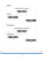
No Read
With No Read turned On, the Imager notifies you if a code cannot be read. If using a Quick*View
Scan Data Window, an “NR” appears when a code cannot be read. If No Read is turned Off, the
“NR” will not appear.
The default no read message of ‘NR’ can be changed to ‘No Read’ by scanning the barcode below:
Output
“No Read”
Default back
to ‘NR’ message
If you want a different notation, for example, “Error,” or “Bad Code,” you can edit the output
message using the Data Formatter. The hex code for the No Read symbol is 9C.
- 21 -
Print Weight
Print Weight is used to adjust the way the imager reads Matrix symbols. If a imager will be seeing
consistently heavily printed matrix symbols, then a print weight of 6 may improve the reading
performance. For consistently light printing, a print weight of 2 may help. After scanning the Set
Print Weight bar code, set the print weight (from 1-7) by scanning digits from Appendix D, then
scanning Save. Default = 4.
Video Reverse
Video Reverse is used to allow the imager to read bar codes that are inverted. The “Off” bar code
below is an example of this type of bar code. If additional menuing is required, Video Reverse must
be disabled to read the menu bar codes and then re-enabled after menuing is completed. Note:
Images downloaded from the unit will not be reversed. This is a setting for decoding only.
- 22 -
- 23 -
Data Editing
Prefix/Suffix Overview
When a bar code is scanned, additional information is sent to the host computer along with the bar
code data. This group of bar code data and additional, user-defined data is called a “message
string.” The selections in this section are used to build the user-defined data into the message
string.
Prefix and Suffix characters are data characters that can be sent before and after scanned data.
You can specify if they should be sent with all symbologies, or only with specific symbologies. The
following illustration shows the breakdown of a message string:
1-11 variable length 1-11 alpha numeric alpha numeric characters characters
Points to Keep In Mind
•
•
•
•
•
It is not necessary to build a message string. The selections in this chapter are only used if
you wish to alter the default settings. Default prefix = None. Default suffix = None.
A prefix or suffix may be added or cleared from one symbology or all symbologies.
You can add any prefix or suffix from the ASCII Conversion Chart (Appendix B), plus Code I.D.
and AIM I.D.
You can string together several entries for several symbologies at one time.
Enter prefixes and suffixes in the order in which you want them to appear on the output.
To Add a Prefix or Suffix:
Step 1. Scan the Add Prefix or Add Suffix symbol
Step 2. Determine the 2 digit Hex value from the Symbology Chart (included in Appendix A) for
the symbology to which you want to apply the prefix or suffix. For example, for Code 128, Code ID
is “j” and Hex ID is “6A”.
Step 3. Scan the 2 hex digits from the Programming Chart (Appendix D) or scan 9, 9 for all
symbologies.
Step 4. Determine the hex value from the ASCII Conversion Chart (Appendix B), for the prefix or
suffix you wish to enter.
Step 5. Scan the 2 digit hex value from the Programming Chart (Appendix D)
Step 6. Repeat Steps 4 and 5 for every prefix or suffix character.
Step 7. To add the Code I.D., scan 5, C, 8, 0.
To add AIM I.D., scan 5, C, 8, 1.
- 24 -
To add a backslash (\), scan 5, C, 5, C.
Note: To add a backslash (\) as in Step 7, you must scan 5C twice
– once to create the leading backslash and then to create the
backslash itself.
Step 8. Scan Save to exit and save, or scan Discard to exit without saving. Repeat
Steps 1-6 to add a prefix or suffix for another symbology.
Example: Add a Suffix to a specific symbology
To send a CR (carriage return)Suffix for UPC only: Step 1. Scan Add Suffix.
Step 2. Determine the 2 digit hex value from the Symbology Chart for UPC.
Step 3. Scan 6, 3 from the Programming Chart Step 4. Determine the hex
value from the ASCII Conversion Chart , for the CR (carriage return). Step 5.
Scan 0, D from the Programming Chart Step 6. Scan Save, or scan Discard
to exit without saving.
To Clear One or All Prefixes or Suffixes:
You can clear a single prefix or suffix, or clear all prefixes/suffixes for a symbology. When you Clear One
Prefix (Suffix), the specific character you select is deleted from the symbology you want. When you Clear
All Prefixes (Suffixes), all the prefixes or suffixes for a symbology are deleted.
Step 1. Scan the Clear One Prefix or Clear One Suffix symbol.
Step 2. Determine the 2 digit Hex value from the Symbology Chart (included in Appendix A) for the
symbology from which you want to clear the prefix or suffix.
Step 3. Scan the 2 digit hex value from the Programming Chart in Appendix D of this manual or scan 9, 9 for
all symbologies.
Your change is automatically saved.
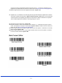
To Add a Carriage Return Suffix to all Symbologies
Scan the following bar code if you wish to add a carriage return suffix to all symbologies at once. This action
first clears all current suffixes, then programs a carriage return suffix for all symbologies.
- 25 -
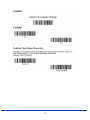
Function Code Transmit
When this selection is enabled and function codes are contained within the scanned data, the imager
transmits the function code to the terminal. Default = Enable.
- 26 -
Intercharacter, Interfunction, and Intermessage Delays
Some terminals drop information (characters) if data comes through too quickly. Intercharacter,
interfunction, and intermessage delays slow the transmission of data, increasing data integrity.
Each delay is composed of a 5 millisecond step. You can program up to 99 steps (of 5 ms each)
for a range of 0-495 ms.
Intercharacter Delay
An intercharacter delay of up to 495 milliseconds may be placed between the transmission of each
character of scanned data. Scan the Intercharacter Delay bar code below, then scan the number
of milliseconds and the SAVE bar code using the Programming Chart (Appendix D)
To remove this delay, scan the Intercharacter Delay bar code, then set the number of steps to 0.
Scan the SAVE bar code using the Programming Chart (Appendix D).
User Specified Intercharacter Delay
An intercharacter delay of up to 495 milliseconds may be placed after the transmission of a
particular character of scanned data. Scan the Delay Length bar code below, then scan the
number of milliseconds and the SAVE bar code using the Programming Chart (Appendix D).
Next, scan the Character to Trigger Delay bar code, then the 2-digit hex value for the ASCII
character that will trigger the delay ASCII Conversion Chart (Appendix B).
To remove this delay, scan the Delay Length bar code, and set the number of steps to 0. Scan the SAVE
bar code using the Programming Chart (Appendix D).
- 27 -
Interfunction Delay
An interfunction delay of up to 495 milliseconds may be placed between the transmission of each
segment of the message string. Scan the Interfunction Delay bar code below, then scan the
number of milliseconds and the SAVE bar code using the Programming Chart (Appendix D)
Interfunction Delays
To remove this delay, scan the Interfunction Delay bar code, then set the number of steps to 0.
Scan the SAVE bar code using the Programming Chart (Appendix D).
Intermessage Delay
An intermessage delay of up to 495 milliseconds may be placed between each scan transmission.
Scan the Intermessage Delay bar code below, then scan the number of milliseconds and the
SAVE bar code using the Programming Chart (Appendix D).
To remove this delay, scan the Intermessage Delay bar code, then set the number of steps to 0.
Scan the SAVE bar code using the Programming Chart (Appendix D).
- 28 -
Data Formatting
Data Format Editor Introduction
You may use the Data Format Editor to change the imager’s output. For example, you can use the
Data Format Editor to insert characters at certain points in bar code data as it is scanned. The
selections in the following pages are used only if you wish to alter the output. Default Data Format
setting = None.
Normally, when you scan a bar code, it gets outputted automatically; however when you do a
format, you must use a “send” command (see Send Commands on page 28) within the format
program to output data.
Multiple formats may be programmed into the imager. They are stacked in the order in which they
are entered. However, the following list presents the order in which formats are applied:
1. Specific Term ID, Actual Code ID, Actual Length
2. Specific Term ID, Actual Code ID, Universal Length
3. Specific Term ID, Universal Code ID, Actual Length
4. Specific Term ID, Universal Code ID, Universal Length
5. Universal Term ID, Actual Code ID, Actual Length
6. Universal Term ID, Actual Code ID, Universal Length
7. Universal Term ID, Universal Code ID, Actual Length
8. Universal Term ID, Universal Code ID, Universal Length
If you have changed data format settings, and wish to clear all formats and return to the factory
defaults, scan the Default Data Format code.
To Add a Data Format
Step 1. Scan the Enter Data Format symbol.
Step 2. Primary/Alternate Format
Determine if this will be your primary data format, or one of 3 alternate formats. (Alternate
formats allow you “single shot” capability to scan one bar code using a different data
format. After the one bar code has been read, the imager reverts to the primary data
format. If you are programming the primary format, scan 0 using the Programming Chart
(Appendix D) If you are programming an alternate format, scan 1, 2, or 3, depending on
the alternate format you are programming.
Step 3. Terminal Type
Scan three numeric bar codes from Appendix D for your terminal ID: 0 0 0 = RS232,
Note: The wildcard for all terminal types is 0 9 9.
Step 4. Code I.D.
In Appendix A, find the symbology to which you want to apply the data format. Locate the
Hex value for that symbology and scan the 2 digit hex value from the Programming Chart
(Appendix D).
Step 5. Length
Specify what length (up to 9999 characters) of data will be acceptable for this symbology.
Scan the four digit data length from the Programming Chart (Appendix D). Note: 50
characters is entered as 0050. 9999 is a universal number, indicating all lengths.
Step 6. Editor Commands
Refer to Data Format Editor Commands. Scan the symbols that represent the command
you want to enter. 94 alphanumeric characters may be entered for each symbology data
format.
Step 7. Scan Save from the Programming Chart (Appendix D)
- 29 -
Other Programming Selections
•
•
•
Clear One Data Format This deletes one data format for one symbology. If you are clearing the
primary format, scan 0 from the Programming Chart (Appendix D). If you are clearing an alternate
format, scan 1, 2, or 3, depending on the alternate format you are clearing. Scan the Terminal
Type and Code I.D. and the bar code data length for the specific data format that you want to
delete. All other formats remain unaffected.
Save from the Programming Chart. This exits, saving any Data Format changes.
Discard from the Programming Chart. This exits without saving any Data Format changes.
Data Format Editor Commands
Send Commands
F1 Send all characters followed by “xx” key or function code, starting from current cursor position. Syntax =
F1xx(xx stands for the hex value for an ASCII code, see ASCII Conversion Chart (Appendix B).
F2 Send “nn” characters followed by “xx” key or function code, starting from current cursor position. Syntax
= F2nnxx(nn stands for the numeric value (00-99) for the number of characters and xx stands for the
hex value for an ASCII code. See ASCII Conversion Chart (Appenix B).
F3 Send up to but not including “ss” character (Search and Send) starting from current cursor position,
leaving cursor pointing to “ss” character followed by “xx” key or function code. Syntax = F3ssxx(ss and
xx both stand for the hex values for ASCII codes, see ASCII Conversion Chart (Appendix B).
F4 Send “xx” character “nn” times (Insert) leaving cursor in current cursor position. Syntax = F4xxnn (xx
stands for the hex value for an ASCII code, see ASCII Conversion Chart (Appendix B) and nn is the
numeric value (00-99) for the number of times it should be sent.)
E9 Send all but the last “nn” characters, starting from the current cursor position. Syntax = E9nn (nn is
the numeric value (00-99) for the number of characters that will not be sent at the end of the
message.)
Move Commands
F5 Move the cursor ahead “nn” characters from current cursor position. Syntax = F5nn (nn stands for the
numeric value (00-99) for the number of characters the cursor should be moved ahead.)
F6 Move the cursor back “nn” characters from current cursor position. Syntax = F6nn (nn stands for the
numeric value (00-99) for the number of characters the cursor should be moved back.)
F7 Move the cursor to the beginning of the data string. Syntax = F7.
EA Move the cursor to the end of the data string. Syntax = EA
Search Commands
F8 Search ahead for “xx” character from current cursor position, leaving cursor pointing to “xx” character.
Syntax = F8xx (xx stands for the hex value for an ASCII code, see see ASCII Conversion Chart
(Appendix B)
F9 Search back for “xx” character from current cursor position, leaving cursor pointing to “xx” character.
Syntax = F9xx (xx stands for the hex value for an ASCII code, see see ASCII Conversion Chart
(Appendix B).
E6 Search ahead for the first non “xx” character from the current cursor position, leaving cursor pointing
to non “xx” character. Syntax = E6xx (xx stands for the hex value for an ASCII code, see ASCII
Conversion Chart (Appendix B).
E7 Search back for the first non “xx” character from the current cursor position, leaving cursor pointing to
non “xx” character. Syntax = E7xx (xx stands for the hex value for an ASCII code, see ASCII
Conversion Chart (Appendix B).
Miscellaneous Commands
FB Suppress all occurrences of up to 15 different characters, starting at the current cursor position, as the
cursor is advanced by other commands. When the FC command is encountered, the suppress function
is terminated. The cursor is not moved by the FB command. Syntax = FBnnxxyy . .zz where nn is a
- 30 -
count of the number of suppressed characters in the list and xxyy .. zz is the list of characters to be
suppressed. (xx stands for the hex value for an ASCII code, see ASCII Conversion Chart (Appendix B)
FC Disables suppress filter and clear all suppressed characters. Syntax = FC.
E4 Replaces up to 15 characters in the data string with user specified characters. Replacement continues
until the E5 command is encountered. Syntax = E4nnxx1xx2yy1yy2...zz1zz2 where nn is the total count
of both characters to be replaced plus replacement characters; xx1 defines characters to be replaced
and xx2 defines replacement characters, continuing through zz1 and zz2.
E5 Terminates character replacement. Syntax = E5.
FE Compare character in current cursor position to the character “xx.” If characters are equal, increment
cursor. If characters are not equal, no format match. Syntax = FExx (xx stands for the hex value for an
ASCII code, see ASCII Conversion Chart (Appendix B).
EC Check to make sure there is an ASCII number at the current cursor position. If character is not numeric,
format is aborted. Syntax = EC.
ED Check to make sure there is a non-numeric ASCII character at the current cursor position. If character
is numeric, format is aborted. Syntax = ED.
- 31 -
- 32 -
Symbologies
This programming section contains the following menu selections.
- 33 -
All Symbologies
If you want to decode all the symbologies allowable for your imager, scan the All Symbologies On
code. If on the other hand, you want to decode only a particular symbology, scan All Symbologies
Off followed by the On symbol for that particular symbology.
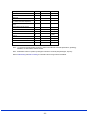
Message Length Description
You are able to set the valid reading length of some of the bar code symbologies. If the data length
of the scanned bar code doesn’t match the valid reading length, the imager will issue an error beep.
You may wish to set the same value for minimum and maximum length to force the imager to read
fixed length bar code data. This helps reduce the chances of a misread.
EXAMPLE: Decode only those bar codes with a count of 9-20 characters. Min. length = 09
Max. length = 20 EXAMPLE: Decode only those bar codes with a count of 15
characters. Min. length = 15 Max. length = 15
For a value other than the minimum and maximum message length defaults, scan the bar codes
included in the explanation of the symbology, then scan the digit value of the message length and
Save bar codes on the Programming Chart (Appendix D). The minimum and maximum lengths and
the defaults are included with the respective symbologies.
- 34 -
- 35 -
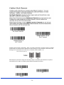
Codabar Concatenation
Codabar supports symbol concatenation. When you enable concatenation, the imager looks for a Codabar
symbol having a “D” start character, adjacent to a symbol having a “D” stop character. In this case the two
messages are concatenated into one with the “D” characters omitted. Default = On.
Character Start Stop Start Stop
Select Require to prevent the imager from decoding a single “D” Codabar symbol without its companion.
This selection has no effect on Codabar symbols without Stop/Start D characters.
- 36 -
Codabar Message Length
Scan the bar codes below to change the message length. Minimum and Maximum lengths = 2-60.
Minimum Default = 4, Maximum Default = 60.
- 37 -
- 38 -
Code 39 Message Length
Scan the bar codes below to change the message length. Minimum and
Maximum lengths = 0-48. Minimum Default = 0, Maximum Default = 48.
Code 39 Append
This function allows the imager to append the data from several Code 39 bar codes together before
transmitting them to the host computer. When this function is enabled, the imager stores those
Code 39 bar codes that start with a space (excluding the start and stop symbols), and does not
immediately transmit the data. The imager stores the data in the order in which the bar codes are
read, deleting the first space from each. The imager transmits the appended data when it reads a
Code 39 bar code that starts with a character other than a space. Default = Off.
- 39 -
Code 32 Pharmaceutical (PARAF)
Code 32 Pharmaceutical is a form of the Code 39 symbology used by Italian pharmacies. This
symbology is also known as PARAF.
Note: Trioptic Code must be turned off while scanning Code 32 Pharmaceutical codes.
- 40 -
FULL ASCII
Full ASCII Code 39 decoding is enabled, certain character pairs within the bar code symbol will be
interpreted as a single character. For example: $V will be decoded as the ASCII character SYN,
and /C will be decoded as the ASCII character #. Default = On.
NUL
%U
SOH
$A
STX
$B
ETX
$C
EOT
$D
ENQ
$E
ACK
$F
BEL
$G
BS
$H
HT
$I
LF
$J
VT
$K
FF
$L
CR
$M
SO
$N
SI
$O
DLE
$P
DC1
$Q
DC2
$R
DC3
$S
DC4
$T
NAK
$U
SYN
$V
ETB
$W
CAN
$X
EM
$Y
SUB
$Z
ESC
%A
FS
%B
GS
%C
RS
%D
US
%E
p
+P
q
+Q
SP
SPACE
0
0
@
%V
P
P
‘
%W
!
/A
1
1
A
A
Q
Q
a
+A
“
/B
2
2
B
B
R
R
b
+B
r +R
s
+S
#
/C
3
3
C
C
S
S
c
+C
$
/D
4
4
D
D
T
T
d
+D
%
/E
5
5
E
E
U
U
e
+E
&
/F
6
6
F
F
V
V
f
+F
‘
/G
7
7
G
G
W
W
g
+G
(
/H
8
8
H
H
X
X
h
+H
)
/I
9
9
I
Y
Y
i
+I
*
/J
:
/Z
J
J
Z
Z
j
+J
+
/K
;
%F
K
K
[
%K
k
+K
,
/L
<
%G
L
L
\
%L
l
+L
-
-
=
%H
M
M
]
%M
m
+M
.
.
>
%I
N
N
^
%N
n
+N
/
/O
?
%J
O
O
%O
o
+O
I
_
t +T
u
+U
v
+V
w
+W
x
+X
y
+Y
z
+Z
{
%P
|
%Q
}
%R
~
%S
DEL
%T
Character pairs /M and /N decode as a minus sign and period respectively. Character
pairs /P through /Y decode as 0 through 9.
- 41 -
Interleaved 2 of 5 (or I 2 of 5)
Check Digit
No Check Digit indicates that the imager reads and transmits bar code data with or without a
check digit.
When Check Digit is set to Validate, but Don’t Transmit, the unit only reads Interleaved 2 of 5
bar codes printed with a check digit, but will not transmit the check digit with the scanned data.
When Check Digit is set to Validate and Transmit, the imager only reads Interleaved 2 of 5 bar
codes printed with a check digit, and will transmit this digit at the end of the scanned data. Default =
No Check Digit.
- 42 -
Interleaved 2 of 5 Message Length
Scan the bar codes below to change the message length. Minimum and Maximum lengths = 2-80. Minimum
Default = 4, Maximum Default = 80.
- 43 -
Code 93
Code 93 Message Length
Scan the bar codes below to change the message length. Minimum and Maximum lengths = 0-80. Minimum
Default = 0, Maximum Default = 80.
- 44 -
Code 2 of 5
Code 2 of 5 Message Length
Scan the bar codes below to change the message length. Minimum and Maximum lengths = 1-48. Minimum
Default = 4, Maximum Default = 48.
- 45 -
IATA Code 2 of 5
IATA Code 2 of 5 Message Length
Scan the bar codes below to change the message length. Minimum and Maximum lengths = 1-48. Minimum
Default = 4, Maximum Default = 48.
- 46 -
Matrix 2 of 5
Matrix 2 of 5 Message Length
Scan the bar codes below to change the message length. Minimum and Maximum lengths = 1-80.
Minimum Default = 4, Maximum Default = 80.
- 47 -
Code 11
Check Digits Required
This option sets whether 1 or 2 check digits are required with Code 11 bar codes. Default = Two
Check Digits.
Code 11 Message Length
Scan the bar codes below to change the message length. Minimum and Maximum lengths = 1-80.
Minimum Default = 4, Maximum Default = 80.
- 48 -
Code 128
ISBT 128 Concatenation
In 1994 the International Society of Blood Transfusion (ISBT) ratified a standard for communicating
critical blood information in a uniform manner. The use of ISBT formats requires a paid license.
The ISBT 128 Application Specification describes 1) the critical data elements for labeling blood
products, 2) the current recommendation to use Code 128 due to its high degree of security and its
space-efficient design, 3) a variation of Code 128 that supports concatenation of neighboring
symbols, and 4) the standard layout for bar codes on a blood product label. Use the bar codes
below to turn concatenation on or off. Default =Off.
- 49 -
Code 128 Message Length
Scan the bar codes below to change the message length. Minimum and Maximum lengths = 0-80.
Minimum Default = 0, Maximum Default = 80.
- 50 -
Telepen
Telepen Output
Using AIM Telepen Output, the imager reads symbols with start/stop pattern 1 and decodes them
as standard full ASCII (start/stop pattern 1). When Original Telepen Output is selected, the imager
reads symbols with start/stop pattern 1 and decodes them as compressed numeric with optional full
ASCII (start/stop pattern 2). Default = AIM Telepen Output.
Telepen Message Length
Scan the bar codes below to change the message length. Minimum and Maximum lengths = 1-60.
Minimum Default = 1, Maximum Default = 60.
- 51 -
UPC-A
UPC-A Check Digit
This selection allows you to specify whether the check digit should be transmitted at the end of the
scanned data or not. Default = On.
UPC-A Number System
The numeric system digit of a U.P.C. symbol is normally transmitted at the beginning of the
scanned data, but the unit can be programmed so it will not transmit it. Default = On.
- 52 -
UPC-A Addenda
This selection adds 2 or 5 digits to the end of all scanned UPC-A data. Default = Off for both 2 Digit
and 5 Digit Addenda.
UPC-A Addenda Required
When Required is scanned, the imager will only read UPC-A bar codes that have addenda. You must then
turn on a 2 or 5 digit addenda. Default = Not Required.
UPC-A Addenda Separator
When this feature is on, there is a space between the data from the bar code and the data from
the addenda. When turned off, there is no space. Default = On.
UPC-A/EAN-13 with Extended Coupon Code
Use the following codes to enable or disable UPC-A and EAN-13 with Extended Coupon Code. Default =
On.
- 53 -
UPC-E0
UPC-E0 Expand
- 54 -
UPC-E0 Addenda Required
When Addenda Required is set to on, the imager will only read UPC-E bar codes that have
addenda. Default = Not Required.
UPC-E0 Addenda Separator
When this feature is on, there is a space between the data from the bar code and
the data from the addenda. When turned off, there is no space.
Default = On.
UPC-E0 Check Digit
Check Digit specifies whether the check digit should be transmitted at the end of the scanned data or not.
Default = On.
- 55 -
EAN/JAN-13
- 56 -
- 57 -
ISBN Translate
This selection causes EAN-13 Bookland symbols to be translated into their equivalent ISBN number format.
Default = Off.
EAN/JAN-8
- 58 -
- 59 -
- 60 -
- 61 -
- 62 -
- 63 -
- 64 -
Code 49 Message Length
Scan the bar codes below to change the message length. Minimum and Maximum lengths = 1-81. Minimum
Default = 1, Maximum Default = 81.
- 65 -
PDF417
PDF417 Message Length
Scan the bar codes below to change the message length. Minimum and Maximum lengths = 1-2750.
Minimum Default = 1, Maximum Default = 2750.
- 66 -
MicroPDF417
- 67 -
UPC/EAN Version
Scan the UPC/EAN Version On bar code to decode EAN•UCC Composite symbols that have a
UPC or EAN linear component. (This does not affect EAN•UCC Composite symbols with a
UCC/EAN-128 or RSS linear component.)
EAN•UCC Composite Code Message Length
Scan the bar codes below to change the message length. Minimum and Maximum lengths = 12435. Minimum Default = 1, Maximum Default = 2435.
- 68 -
EAN•UCC Emulation
The imager can automatically format the output from any EAN•UCC data carrier to emulate what
would be encoded in an equivalent UCC/EAN-128 or RSS and Composite symbol. EAN•UCC data
carriers include UPC-A and UPC-E, EAN-13 and EAN-8, ITF-14, UCC/EAN-128, and EAN•UCC
RSS and Composites. Data from 2D symbols such as Aztec Code, Data Matrix, or QR Code,
which encode a leading FNC1, also invoke EAN•UCC emulation. If UCC/EAN-128 Emulation is
selected, the AIM Symbology Identifier is reported as “]C1”. If RSS Emulation is selected, the AIM
Symbology Identifier is reported as “]e0.” Any application that accepts EAN•UCC data can be
simplified since it only needs to recognize one data carrier type. Default = No Emulation.
TCIF Linked Code 39 (TLC39)
This code is a composite code since it has a Code 39 linear component and a MicroPDF417
stacked code component. All bar code readers are capable of reading the Code 39 linear
component. The MicroPDF417 component can only be decoded if TLC39 On is selected. The
linear component may be decoded as Code 39 even if TLC39 is off.
- 69 -
Postal Symbologies
Postal Codes
Note: For best performance when reading a postal symbology, all other postal symbologies should be
turned off.
- 70 -
- 71 -
China Post
China Post Message Length
Scan the bar codes below to change the message length. Minimum and Maximum lengths = 0-80.
Minimum Default = 4, Maximum Default = 80.
- 72 -
Korea Post
Korea Post Message Length
Scan the bar codes below to change the message length. Minimum and Maximum lengths = 2-80.
Minimum Default = 4, Maximum Default = 48.
- 73 -
2D Matrix Symbologies
QR Code
QR Code Message Length
Scan the bar codes below to change the message length. Minimum and Maximum
lengths = 1-3500. Minimum Default = 1, Maximum Default = 3500.
- 74 -
Data Matrix
Data Matrix Message Length
Scan the bar codes below to change the message length. Minimum and Maximum lengths = 1-1500.
Minimum Default = 1, Maximum Default = 1500.
- 75 -
MaxiCode
MaxiCode Message Length
Scan the bar codes below to change the message length. Minimum and Maximum lengths = 1-150.
Minimum Default = 1, Maximum Default = 150.
- 76 -
Aztec Code
Aztec Code Message Length
Scan the bar codes below to change the message length. Minimum and Maximum lengths = 1-3750.
Minimum Default = 1, Maximum Default = 3750.
Aztec Runes
Select Enable Runes if you are scanning Aztec runes, which are the smallest type of Aztec Code symbol
with the ability to encode a very short license plate message.
- 77 -
OCR Programming
- 78 -
OCR
Default All OCR Settings turns off all OCR capability in the imager, so the imager will be able to scan
linear, stacked, matrix, and composite bar codes, but not OCR fonts. In addition, any OCR templates you
have created are erased. The 8 digit default templates are reinstated for any future use of the OCR On
codes listed below.
OCR
Note: OCR symbols can misread when scanned sideways or upside down. Use Working Orientation if your
OCR symbols will not usually be presented upright to the scanner.
Only one OCR symbology can be read at a time.
OCR-A On allows you to scan characters in the OCR-A font. The default setting allows you to scan any 8
digit combination. If you have created an OCR template, character combinations that fit the template can be
scanned (see Creating an OCR Template, page 82).
OCR-B On allows you to scan characters in the OCR-B font. The default setting allows you to scan any 8
digit combination. If you have created an OCR template, character combinations that fit the template can be
scanned (see Creating an OCR Template, page 82).
- 79 -
U.S. Currency
U.S. Currency On allows you to scan characters in the font used on U.S. currency. The default setting
allows you to scan any 8 digit combination. If you have created an OCR template, character combinations
that fit the template can be scanned.
MICR E13 B
MICR E13 B On allows you to scan MICR characters on a bank check. The default setting allows you to
scan any 8 digit combination. If you have created an OCR template, character combinations that fit the
template can be scanned.
SEMI Font
SEMI Font On allows you to scan the SEMI font used in the semiconductor industry.
All OCR Off turns off all OCR capability in the imager, so the imager will be able to scan linear, stacked,
matrix, and composite bar codes, but not OCR fonts. However, any OCR templates you have created will
be retained in memory.
- 80 -
Creating OCR Templates
You can create a custom “template,” or character string that defines the length and content of OCR strings
that will be read with your imager. There are several choices when creating a custom template for your
application. You can create a template for a single format, you can string together several formats, and you
can create a template for a user-defined variable. These choices are described in detail below.
Creating an OCR Template
A single template allows you to program the imager to read any combination of characters in the order you
specify. Refer to examples that follow the Template Characters table below.
Template Characters
a
represents any alphanumeric character (digit or letter)
c
represents a check character position
d
represents any digit
e
represents any available OCR character
g
represents character from user-defined variable “g”
h
represents character from user-defined variable “h”
l
represents any uppercase letter
t
marks the start of a new template
r
multi row indicator
All other characters represent themselves. Spaces can be used.
To Add an OCR Template
1.
2.
Begin building the template. Scan the Enter OCR Template symbol.
Scan the characters for the string. Use the Template Characters chart above to determine what
characters you need to create your format. Use the OCR Programming Chart (after the Sample
Codes in Appendix D) to scan the characters for your template.
Example A: You need to read any combination of 8 digits. The template would be:
dddddddd
To create this template, you would scan the Enter OCR Template symbol, then scan the d from the
OCR Programming Chart after the Sample Codes (in Appendix D) 8 times. Scan Save OCR Template.
This would let you read any string of 8 digits, for example:
37680981
3. Character Match Sequences On the ASCII Conversion Chart (Appendix B), find the Hex value that
represents the character(s) you want to match. Use the Programming Chart (Appendix D) to scan the
numbers that represent these characters.
Example B: You need to read 3 digits, 3 specific characters (ABC), 3 digits. The template would be:
ddd414243ddd
- 81 -
}
hex codes for
letters A, B, and C
To create this template, you would scan the Enter OCR Template symbol, scan the d from the Sample
Symbols (see Appendix D) 3 times, scan 414243 from Appendix D (the hex characters for “A,” “B,” and
“C”), then scan the d from Appendix D 3 more times. Scan Save OCR Template. This would let you read
any string of 3 digits, “ABC,” then any string of 3 digits, for example:
551ABC983
4. Adding Spaces You may also need to put spaces in your template.
Example C: You need to read 3 digits, space, 3 specific characters (ABC), space, 3 digits. The template
would be:
ddd2041424320ddd
hex code for a space
To create this template, you would scan the Enter OCR Template symbol, scan the d from the OCR
Programming Chart after the Sample Codes in the back of this manual 3 times, scan 2041424320 from the
Programming Chart in Appendix D (the hex characters for “space,” “A,” “B,” “C,” “space”), then scan the d
from Appendix D 3 more times. Scan Save OCR Template (page 80). This would let you read any string of
3 digits, space, “ABC,” space, then any string of 3 digits, for example:
551 ABC 983
Note: If using Quick*View to program, use the space bar to designate a space and not the hex value of 20.
5. Exit OCR Template Editor Scan Save OCR Template to save your entries. Discard OCR Template exits
without saving any OCR Template changes.
Stringing Together Multiple Formats (Creating “Or” Statements)
You may want to program the imager to accept many OCR formats. To do this, you would string together
each format with a “t.” This tells the imager to read optical characters that match any one of the formats in
the template.
Example D: You need to read any combination of 8 digits, ora combination of 4 digits, 2 uppercase
letters, and 2 digits. The template would be:
ddddddddtddddlldd
To create this template, you would scan the Enter OCR Template symbol (page 80), scan the d from the
OCR Programming Chart after the Sample Codes in the back of this manual 8 times, then scan the t to
create the “or” statement. Then you would scan the characters for the 2nd template. Scan the d 4 times,
scan l 2 times, then scan d 2 more times. Scan Save OCR Template (page 80). This would let you read
either type of format, for example:
99028650
or
- 82 -
9902XZ50
You can string together as many templates as you need.
Creating a User-Defined Variable
You can create up to two of your own user variables for an OCR template. These variables will represent
any OCR readable characters. The user-defined variables are stored under the letters “g” and “h.” Creating
a user variable follows the same steps as creating a template, but instead of scanning the Enter OCR
Template symbol, you scan the Enter User-Defined Variable symbol . The letters g and h can then be
used in an OCR template to define the variable you specified.
Example E: You need a variable to represent the letters “A,” “B,” or “C.” The template for this variable
would be:
414243
To create the template, you would scan the Enter User-Defined Variable g symbol. Scan 414243 from
Appendix D (the hex characters for “A,” “B,” and “C”). Scan Save OCR Template. This will let you read
either A or B or C in any position where you place the g. For example, you could create the following
template:
ddddddggg
This template would then let you read data that began with 6 digits, and had an A, B, or C trailing. So you
would be able to read:
654321ABC
or
654321BAC
or
654321CCC
Reading Multi-Row OCR
The OEM Engine is capable of decoding multi-row OCR text. Consider the following example. This example
shows serial commands as would be entered using Quick*View.
Example G: You need to read multiple rows of OCR data as shown below:
12345678 ABCDEFGH
To read the first row of OCR data, you would menu the following template:
OCRTMP"dddddddd".
This template is the default OCR template. If you wanted to read the second line of data, you would use
the following template:
OCRTMP"llllllll".
To read both lines of OCR at one time, use the variable rto indicate the start of a new row. All of the other
templating variables for the individual rows work the same as previously described. For instance, in the
above example, you would use the following template to read both rows:
OCRTMP"ddddddddrllllllll".
To read the three rows below, you would use the template command
"OCRTMP"ddddddddrllllllllrlllldddd".
- 83 -
Adding an OCR Check Character
You may want to print and verify a check character in order to enhance the security of your OCR
application. The OEM Engine can be programmed for almost any type of check character. A number of
presets are provided for common check character uses (e.g., modulo 10 and modulo 36).
Scan the OCR Modulo 10 or OCR Modulo 36 Check Character bar code to specify the type of check
character used in the OCR strings you’re scanning. The imager will then only read OCR character strings
with a valid check character. The OEM Engine transmits the OCR data without the check character data.
You must specify the location of the check character in the template with a c.
Example F: You need to read any combination of 7 digits, with a modulo 10 check character in the 8th
position. The template would be:
dddddddc
To create this template, you would scan the Modulo 10 Check Character symbol. Then scan the Enter
OCR Template symbol, scan the d from Appendix D 7 times, and scan the c once. Scan Save OCR
Template. This template will let you read any combination of 6 digits with a correct check character after.
(If the check character is invalid, the imager will issue an error beep.) For example, the following string
could be scanned:
01234569
and the output would be: 0123456
OCR Modulo 10 Check Character
Scan this symbol to program the OCR template for a simple modulo 10 checksum of the digits 0
through 9.
- 84 -
OCR Modulo 36 Character Set
Scan this symbol to program the OCR template for a simple modulo 36 checksum of
the digits 0 through 9 and the letters A through Z.
OCR Modulo 36 Check Character
OCR Template Codes
Note: Reading more than three rows of OCR is not recommended. Contact the factory if you have an
application that requires reading 4 or more rows of OCR.
† One or more two-digit numbers and Save are required after reading this programming symbol. Refer to
the Programming Chart in Appendix D of this manual.
Exit Selections
- 85 -
To Add a Test Code I.D. Prefix to All Symbologies
This selection allows you to turn on transmission of a Code I.D. before the decoded symbology.
(See the Symbology Chart, included in the Appendix A, for the single character code that identifies
each symbology.) This action first clears all current prefixes, then programs a Code I.D. prefix for
all symbologies. This is a temporary setting that will be removed when the unit is power cycled.
Show Software Revision
Scan the bar code below to output the current software revision, unit serial number, and other product
information.
Show Data Format
Scan the bar code below to show current data format settings.
Resetting the Standard Product Defaults
If you aren’t sure what programming options are in your imager, or you’ve changed some options and want
the standard product default settings restored, scan the Standard Product Default Settings bar code
below.
- 86 -
Test Menu
When you scan the Test Menu On code, then scan a programming code in this manual, the imager displays
the content of a programming code. The programming function will still occur, but in addition, the content of
that programming code is output to the terminal.
Note: This feature should not be used during normal imager operation.
Quick*View
Quick*View is a Microsoft Windows program that displays decoded symbol messages and captures
images (for instance, ID photographs) from the OEM Engine. Bar code information and images are
displayed in the Quick*View window.
Temporary Quick*View Configuration
For a quick download communication configuration, scan the Quick*View bar code and the imager will be
temporarily configured for Quick*View settings.
Note: Scan the bar code below and the unit will communicate in RS-232 mode, allowing it to work with
Quick*View. To convert the imager back to the original settings, cycle the power.
- 87 -
APPENDIX A: Symbology Chart
Symbology
AIM ID
Possible AIM
ID Modifiers
(m)
All Symbologies
HHP Code
ID (hex)
(0x99)
Australian Post
]X0
Aztec Code
]zm
British Post
]X0
B (0x42)
Canadian Post
]X0
C (0x43)
China Post
]X0
Q (0x51)
Codabar
]Fm
0-1
Codablock F
]Om
0, 1, 4, 5, 6
Code 11
]H3
Code 128
]Cm
0, 1, 2, 4
j (0x6A)
Code 16K
]Km
0, 1, 2, 4
o (0x6F)
Code 32 Pharmaceutical (PARAF)
]X0
Code 39
]Am
Code 49
]Tm
Code 93 and 93i
]Gm
A (0x41)
0-9, A-C
z (0x7A)
a (0x61)
q (0x71)
h (0x68)
< (0x3C)
0, 1, 3, 4, 5, 7
0, 1, 2, 4
0-9, A-Z, a-m
b (0x62)
l (0x6C
i (0x69
Data Matrix
]dm
EAN- 13
]E0
d (0x64)
EAN- 8
]E4
D (0x44)
0-6
w (0x77)
EAN•UCC Composite
]em
EAN-13 with Extended Coupon Code
]E3
Interleaved 2 of 5
]lm
Japanese Post
]X0
J (0x4A)
KIX (Netherlands) Post
]X0
K (0x4B)
Korea Post
]X0
? (0x3F)
Matrix 2 of 5
]X0
m (0x6D)
MaxiCode
]Um
0-3
x (0x78)
AIM ID
Possible AIM
ID Modifiers
(m)
HHP Code
ID (hex)
Symbology
0-3
y (0x79)
d (0x64)
0, 1, 3
e (0x65)
MICR E 13 B
]ZE
MicroPDF417
“ (0x22)
]Lm
3-5
R (0x52)
MSI
]Mm
0
g (0x67)
OCR-A
]o1
O (0x4F)
OCR-B
]o2
O (0x4F)
OCR US Money Font
]o3
O (0x4F)
SEMI Font
]o3
O (0x4F)
PDF417
]Lm
Planet Code
]X0
0-2
r (0x72)
L (0x4C)
- 88 -
Plessey Code
]P0
PosiCode
]pm
Postnet
]X0
QR Code
]Qm
0-6
s (0x73)
Reduced Space Symbology (RSS14, RSS Limited, RSS Expanded)
]em
0
y (0x79)
Straight 2 of 5 IATA (two-bar start/
stop)
]Rm
0, 1, 3
f (0x66)
TCIF Linked Code 39 (TLC39)
]L2
Telepen
]Bm
Trioptic Code
]X0
= (0x3D)
UCC/EAN-128
]C1
I (0x49)
UPC-A
]E0
c (0x63)
UPC-A with Extended Coupon Code
]E3
c (0x63)
UPC-E
]E0
E (0x45)
VeriCode
]X0
v (0x76)
n (0x6E)
0, 1, 2
W (0x57)
P (0x50)
T (0x54)
0, 1, 2, 4
t (0x74)
Note: “m” represents the AIM modifier character. Refer to International Technical Specification, Symbology
Identifiers, for AIM modifier character details.
Note: Prefix/Suffix entries for specific symbologies override the universal (All Symbologies, 99) entry.
Refer to Data Editing and Data Formatting for information about using Code ID and AIM ID.
- 89 -
APPENDIX B: ASCII Conversion Chart
Dec
Hex
Char
Dec
Hex
Char
Dec
Hex
Char
Dec
Hex
Char
0
00
NUL
32
20
SOH
33
21
!
64
40
@
96
60
‘
65
41
A
97
61
a
STX
34
22
“
66
42
B
98
62
b
ETX
35
EOT
36
23
#
67
43
C
99
63
c
24
$
68
44
D
100
64
d
ENQ
ACK
37
25
%
69
45
E
101
65
e
38
26
&
70
46
F
102
66
f
BEL
39
27
‘
71
47
G
103
67
g
BS
40
28
(
72
48
H
104
68
h
HT
41
29
)
73
49
l
105
69
i
0A
LF
42
2A
*
74
4A
J
106
6A
j
0B
VT
43
2B
+
75
4B
K
107
6B
k
0C
FF
44
2C
,
76
4C
L
108
6C
l
0D
CR
45
2D
-
77
4D
M
109
6D
m
0E
SO
46
2E
.
78
4E
N
110
6E
n
0F
SI
47
2F
/
79
4F
O
111
6F
o
10
DLE
48
30
0
80
50
P
112
70
p
11
DC1
49
31
81
51
Q
113
71
q
12
DC2
50
32
82
52
R
114
72
r
13
DC3
51
33
83
53
S
115
73
s
14
DC4
52
34
84
54
T
116
74
t
15
NAK
53
35
85
55
U
117
75
u
16
SYN
54
36
86
56
V
118
76
v
17
ETB
55
37
87
57
W
119
77
w
18
CAN
56
38
88
58
X
120
78
x
19
EM
57
39
89
59
Y
121
79
y
1A
SUB
58
3A
:
90
5A
Z
122
7A
z
1B
ESC
59
3B
;
91
5B
[
123
7B
{
1C
FS
60
3C
<
92
5C
\
124
7C
|
1D
GS
61
3D
=
93
5D
]
125
7D
}
1E
RS
62
3E
>
94
5E
7E
~
US
63
3F
?
95
5F
^
_
126
1F
127
7F
- 90 -
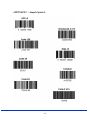
APPENDIX C – Sample Symbols
- 91 -
- 92 -
APPENDIX D – Programming Charts
- 93 -
APPENDIX D – Programming Charts
- 94 -
APPENDIX D – Programming Charts
- 95 -
8012076/2007-04 ∙ HaWa <PM6.5/Word/PDF>/VD ∙ Printed in Germany ∙ Subject to change without notice ∙ The specified product features and technical data do not represent any guarantee ∙ 05 Pre int61
Australia
Phone+61 3 9497 4100
1800 33 48 02 – tollfree
E-Mail [email protected]
Belgium/Luxembourg
Phone +32 (0)2 466 55 66
E-Mail [email protected]
Brasil
Phone+55 11 3215-4900
E-Mail [email protected]
Ceská Republika
Phone+420 2 57 91 18 50
E-Mail [email protected]
China
Phone+852-2763 6966
E-Mail [email protected]
Danmark
Phone+45 45 82 64 00
E-Mail [email protected]
Deutschland
Phone+49 211 5301-270
E-Mail [email protected]
España
Phone+34 93 480 31 00
E-Mail [email protected]
France
Phone+33 1 64 62 35 00
E-Mail [email protected]
Great Britain
Phone+44 (0)1727 831121
E-Mail [email protected]
India
Phone+91–22–4033 8333
E-Mail [email protected]
Israel
Phone+972-4-999-0590
E-Mail [email protected]
Italia
Phone+39 02 27 43 41
E-Mail [email protected]
Österreich
Phone+43 (0)22 36 62 28 8-0
E-Mail [email protected]
Polska
Phone+48 22 837 40 50
E-Mail [email protected]
Republic of Korea
Phone+82-2 786 6321/4
E-Mail [email protected]
Republika Slowenija
Phone+386 (0)1-47 69 990
E-Mail [email protected]
România
Phone+40 356 171 120
E-Mail [email protected]
Russia
Phone+7 495 775 05 34
E-Mail [email protected]
Schweiz
Phone+41 41 619 29 39
E-Mail [email protected]
Singapore
Phone+65 6744 3732
E-Mail [email protected]
Suomi
Phone+358-9-25 15 800
E-Mail [email protected]
Sverige
Phone+46 10 110 10 00
E-Mail [email protected]
Taiwan
Phone+886 2 2365-6292
E-Mail [email protected]
Türkiye
Phone+90 216 587 74 00
E-Mail [email protected]
USA/Canada/México
Phone+1(952) 941-6780
1 800-325-7425 – tollfree
E-Mail [email protected]
Japan
Phone+81 (0)3 3358 1341
E-Mail [email protected]
Nederlands
Phone+31 (0)30 229 25 44
E-Mail [email protected]
Norge Phone+47 67 81 50 00
E-Mail [email protected]
SICK AG | Waldkirch | Germany | www.sick.com
More representatives and agencies
in all major industrial nations at
www.sick.com