1
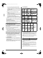
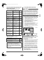
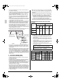
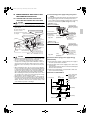
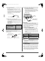
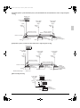
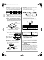
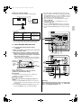
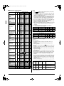
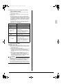
00_3P130768-1B_CV.fm Page 1 Friday, April 1, 2005 8:39 AM
INSTALLATION MANUAL
Total Heat Exchanger
HRV (Heat Reclaim Ventilation) -with DX CoilMODELS
(Ceiling mounted duct type)
With DX coil & Humidifier
English
Deutsch
Français
With DX coil
Español
VKM50GMV1
VKM80GMV1
VKM100GMV1
VKM50GV1
VKM80GV1
VKM100GV1
HRV
HRV;Heat Reclaim Ventilation
Please read this installation manual carefully and install the unit properly to keep it at full capacity for a long time.
Please provide some necessary parts, for example round hoods, air suction/discharge grilles etc., before the installation of the unit.
Italiano
ΕλληνικÜ
Nederlands
HRV;Wärmerückgewinnungslüftung
Lesen Sie dieses Installationshandbuch bitte sorgfältig durch, und installieren Sie die Einheit korrekt, so daß sie ihre Leistungsfähigkeit noch lange
Zeit behält.
Einige erforderliche Teile wie z. B. Rundkappen, Luftansaug-/Lufausblasgitter müssen bereits vor der Installation der Einheit vorhanden sein.
Portugues
HRV;Ventilation avec récupération de chaleur
Veuillez lire attentivement ce Manuel d’installation et installer correctement l’appareil de manière à ce qu’il puisse être utilisé pendant une longue
période de temps sans aucun dérangement.
Veuillez vous procurer certains éléments nécessaires, tels que des capuchons de formes arrondies, des grilles d’aspiration/évacuation d’air.,avant
l’installation de cette unité.
HRV;Ventilación con recuperación de calor
Por favor lea cuidadosamente el manual de instalacion e instale correctamente la unided para que pueda conservar su plena capacidad durante un
largo periodo.
Por favor, antes de proceder a la instalacion de la unidad, proporcione las piezas necesarias, por ejemple tapas redondas, rejillas de aspiracion y de
impulsion de aire, etc.
HRV;Ventilazione per recupero del calore
Leggere attentamente questo mauale ed installare correttamente l’unit in modo da farla funzionare a lungo al massimo delle sue capacita.
Prima dell’installazione, è opportuno disporuno delle partinec-essarie, come ganci arrotondati, griglie di aspirazione/di mandata, ecc.
HRV;Αερισìüò ìε ανÜκτηση θερìüτηταò
ÄιαβÜστε προσεκτικÜ το παρüν εγχειρßδιο εγκατÜστασηò και εγκαταστÞστε σωστÜ τη ìονÜδα για να διατηρÞσετε την πλÞρη απüδοσÞ τηò
για πολý καιρü.
Προìηθεìτεßτε ìερικÜ απαραßτητα εξαρτÞìατα π.χ. κυκλικÜ καλýììατα, εσχÜρεξ αναρρüφησηò/κατÜθλιψηò κ.τ.λ. πριν εγκαταστÞσετε τη
ìονÜδα.
HRV;Hergebruik van warmte
Lees eerst zorgvuldig deze installatiehandleiding en installeer de unit op de juiste manier, zodat deze gedurende lange tijd zijn volledige vermogen
kan leveren.
Zorg dat alle componenten aanwezig zijn, zoals ronde kappen, luchtaan-en afvoerroosters etc. voordat u de unit gaat installeren.
HRV;Ventilação de Recuperação Térmica
Leia atentamente este manual e instale correctamente esta unidade para que esta funcione inteiramente durante um longo período de tempo.
Adquira algumas peças necessárias, por exemplo, tampas redondas, grelhas de aspiração/exaustão, etc., antes da instalação da unidade.
HRV;Вентиляция с реãенерацией тепла
Внимательно ознаêомьтесь с данным рóêоводством и óстановите блоê надлежащим образом, чтобы он работал на полнóю
мощность в течение долãоãо времени.
Перед óстановêой блоêа подãотовьте необходимые детали, например êолпаê оêрóãлой формы, решетêи всасывания/выпóсêа
воздóха и т.п.
Рóссêий
EN60335-2-40,
VKM100GMV1, VKM100GV1
VKM80GMV1, VKM80GV1
VKM50GMV1, VKM50GV1
DAIKIN INDUSTRIES, LTD.
3P155750-1
Yoshiaki Hirata
Manager Quality Control Department
Sakai, 1st of Feb. 2005
Umeda Center Bldg., 4-12, Nakazaki-Nishi 2-chome,
Kita-ku, Osaka, 530-8323 Japan
59277-KRQ/ECM95-4303
KEMA
DAIKIN.TCF.009
01_3P130768-1A_En.fm Page 1 Wednesday, March 23, 2005 7:00 PM
With DX coil &Humidifier
VKM50GMV1
VKM80GMV1
VKM100GMV1
With DX coil
VKM50GV1
VKM80GV1
VKM100GV1
CONTENTS
1
2
3
4
5
6
7
8
9
10
SAFETY CONSIDERATIONS ........................................ 1
BEFORE INSTALLATION ............................................... 2
SELECTING INSTALLATION SITE ................................ 3
PREPARATIONS BEFORE INSTALLATION................... 4
THE METHOD OF INSTALLATION ................................ 4
DRAIN PIPING AND WATER SUPPLY WORK .............. 5
REFRIGERANT PIPING WORK .................................... 6
DUCT CONNECTION .................................................... 7
ELECTRIC WIRING WORK ........................................... 8
WIRING EXAMPLE AND HOW TO SET
THE REMOTE CONTROLLER ...................................... 9
11 FIELD SETTING AND TEST RUN ............................... 13
12 WIRING DIAGRAM ...................................................... 16
1
SAFETY CONSIDERATIONS
Please read these “SAFETY CONSIDERATIONS” carefully
before installing HRV and be sure to install it correctly.
The safety precautions listed here are divided into two categories.
In either case, important safety information is listed which must
be read carefully.
WARNING ............. Failure to observe a warning may
result in death or serious injury.
CAUTION ............... Failure to observe a caution may result
in injury or damage to the equipment.
These too might lead to serious injury
depending on the circumstances.
After completing the installation, make sure that the unit operates properly during the start-up operation. Please instruct the
customer on how to operate the unit and keep it maintained.
Also, inform customers that they should store this installation
manual along with the operation manual for future reference.
WARNING
• Ask your dealer or qualified personnel to carry out installation
work. Do not try to install the machine yourself.
Improper installation may result in water leakage, electric
shocks or fire.
• Installation should be done following the installation manual
and no changes should be made to the unit.
Incorrect installation may cause leaking, electric shocks, or
fire. Injuries may result if the HRV falls.
• Install the unit on a foundation strong enough to withstand
the weight of the unit.
A foundation of insufficient strength may result in the equipment falling and causing injuries.
• Do not allow exhaust air to enter the outside air intake vent.
This may cause the air of the room to become contaminated,
harming the health.
• Locate the outside air intake vent so that it does not take in
exhaust air which contains combustion air, etc.
Incorrect installation may cause a loss of oxygen in the room,
leading to serious accidents.
• Make sure that a separate power supply circuit is provided for
this unit and that all electrical work is carried out by qualified
personnel according to local laws and regulations and this
installation manual.
An insufficient power supply capacity or improper electrical
construction may lead to electric shocks or fire.
Insufficient power supply capacity or incorrect wiring may
cause electrical shocks or fire.
English
Total Heat Exchanger
HRV(Heat Reclaim Ventilation) -with DX Coil-
Installation
manual
• Use only accessories and manufacturer-specified parts
when installing.
The use of parts other than specified may cause drop of the
unit, water leakage, electric shock, fire or other accidents.
• Be sure to ground.
Do not connect the ground wire to gas or water pipes, lightning rod or a telephone ground wire.
Incomplete grounding may result in electric shocks.
• Make sure that all wiring is secured, the specified wires are used,
and no external forces act on the terminal connections or wires.
Improper connections or installation may result in overheating or fire.
• When wiring the power supply and connecting the remote
controller wiring and transmission wiring, position the wires
so that the electric parts box lid can be securely fastened.
Improper positioning of the electric parts box lid may result in
electric shocks, fire or the terminals overheating.
• When installing the unit in a small room, take measures
against to keep refrigerant concentration from exceeding
allowable safety limits in the event of refrigerant leakage.
Contact the place of purchase for more information.
Excessive refrigerant in a closed ambient can lead to oxygen
deficiency.
• If the refrigerant gas leaks during installation, ventilate the
area immediately.
Toxic gas may be produced if the refrigerant gas comes into
contact with fire.
• After completing the installation work, check that the refrigerant gas does not leak.
Toxic gas may be produced if the refrigerant gas leaks into
the room and comes into contact with a source of fire, such
as a fan heater, stove or cooker.
• Do not directly touch any refrigerant which has leaked out of
refrigerant piping connections, etc.
This may cause frostbite.
CAUTION
• Be sure to install an earth leakage breaker.
Failure to install an earth leakage breaker may result in electric shocks or fire.
• Install the indoor and outdoor units, power supply wiring and
connecting wires at least 1 meter away from televisions or
radios in order to prevent image interference or noise.
(Depending on the radio waves, a distance of 1 meter may
not be sufficient enough to eliminate the noise.)
• While following the instructions in this installation manual,
install drain piping in order to ensure proper drainage and
insulate piping in order to prevent condensation.
Improper drain piping may result in water leakage and property damage.
• Install the two outdoor ducts with down slope to prevent rainwater from entering the unit.
If this is not done completely, water may enter the building,
may damage furniture, and cause electric shocks and fire.
• Insulate the two outdoor ducts and the supply air duct to prevent condensation.
If this is not done completely, water may enter the building,
may damage furniture, etc.
• Insulate the duct and the wall electrically when a metal duct
is to be penetrated through the metal lattice and wire lattice
or metal lining of a wooden structure wall.
Inproper duct work may cause electric shocks or fire.
• Do not install the unit in the following locations:
a. Place subjected to high temperature or direct flame.
May result in fire or overheating.
b. Where a mineral oil mist or an oil spray or vapor is produced, for example in a kitchen.
This may cause fire.
1
01_3P130768-1A_En.fm Page 2 Wednesday, March 23, 2005 7:00 PM
c. Place such as machinery plant and chemical plant
where gas, which contains noxious gas or corrosive
components of materials such as acid, alkali organic solvent and paint, is generated. Place where combustible
gas leakage is likely.
Copper piping and brazed joints may corrode, causing
refrigerant to leak or poisoning and fire due to leaked
gas.
d. Place such as bathroom subjected to moisture.
Electric leak or electric shocks and other failure can be
caused.
e. Locations below freezing point.
Using the unit at temperatures below 0°C may cause the
drain pan the supply and discharge piping, the humidifying element, the solenoid valves, and other parts to
freeze, which can cause accidents.
f. Near machinery emitting electromagnetic waves.
Electromagnetic waves may disturb the operation of the
control system and result in a malfunction of the equipment.
• Make sure the temperature and humidity near the unit and
the air suction/discharge air grille is within limit dictated by
the usage conditions.
Do not install in refrigerated truck or other locations with low
temperatures or near heated pools.
This may cause fires or short circuits.
• Make sure that a snow protection measure is taken. If no protection snow may enter through the outdoor ducts, and cause
damaging furniture and electric shock and fire.
2
BEFORE INSTALLATION
The accessories needed for installation must be retained in
your custody until the installation work is completed. Do
not discard them!
After carrying in the unit, protect it with packing materials to prevent it from scratching until installation work is done.
2. 2 ACCESSORIES
Check the following accessories are included with your unit.
Name
Duct connecting
flange
M4 tapping
screw (For
connecting
duct)
Quantity
4 pcs.
24 pcs.
Hold the unit by the hanger brackets (4) when opening the
crate and moving it, and do not lift it holding on to any other
part (especially the refrigerant piping, the drain piping, the
water supply piping, and the duct connecting flange).
• Be sure to check the type of R410A refrigerant to be used
before installing the unit. (Using an incorrect refrigerant will
prevent normal operation of the unit.)
• For the installation of an outdoor unit, refer to the installation manual attached to the outdoor unit.
VKM-GMV1:
VKM-GV1:
1 pc.
0 pc.
Shape
Name
Quantity
Half-union
joint
(Copper
piping joint)
Flare nut
(Copper
piping joint)
Refrigerant piping
insulation cover
VKM-GMV1:1 pc. VKM-GMV1:1 pc.
VKM-GV1: 0 pc. VKM-GV1: 0 pc.
1 set
Shape
I.D.: φ35
Name
Water supply piping Sealing
insulation material
cover
VKM-GMV1:
1 pc.
Quantity
VKM-GV1:
0 pc.
[1] Decide upon a line of transport.
[2] Leave the unit inside its packaging while moving, until reaching the installation site. Where unpacking is unavoidable,
use a sling of soft material or protective plates together with
a rope when lifting, to avoid damage or scratches to the unit.
Water supply piping
with strainer
Shape
1 pc.
I.D.: φ26
Clamp
(Other)
VKM-GMV1:
8 pcs.
• Installation
VKM-GV1:
manual
6 pcs.
• Operation
manual
I.D.: φ15
2. 3 OPTIONAL ACCESSORIES
• This unit can be made a part of two different systems: as part
of the combined operation system used together with VRVII
SYSTEM Air Conditioners, and as the independent system
using only the HRV. An operating remote controller is
required for this unit when using the unit as an independent
system.
Select a suitable remote controller from below table according to customer request and technical materials.
2. 1 PRECAUTIONS
• Be sure to instruct customers how to properly operate the
unit (especially maintenance of air filter, and operation procedure) by having them carry out operations themselves while
looking at the manual.
• Where the air contains high levels of salt such as that near
the ocean and where voltage fluctuates greatly such as that
in factories. Also in vehicles or vessels.
2
Table
Remote controller type
BRC1A62, BRC1D527
NOTE) 1
If you use the remote controller which is not listed in above
table, please consult your dealer.
NOTE) 2
We recommend the remote controller “BRC1D527” especially when the unit is used as independent system. Because
it displays the ventilation mode and can be selected ventilation fan mode with the button.
• When installing the unit, have ready the round shape hood,
the air discharge grille and the air suction grille, and other
parts needed for the installation.
Consult your Daikin dealer when selecting optional accessories.
English
01_3P130768-1A_En.fm Page 3 Wednesday, March 23, 2005 7:00 PM
FOR THE FOLLOWING ITEMS, TAKE SPECIAL CARE
DURING CONSTRUCTION AND CHECK AFTER
INSTALLATION IS FINISHED.
a. Items to be checked after completion of work
Items to be checked
If not properly done,
what is likely to occur
Are the indoor and
outdoor unit fixed
firmly?
The units may drop,
vibrate or make noise.
Is the outdoor duct
installed to outside
with down slope?
(Refer to page 8 Fig. 16)
Condensate water
may drip.
Is the gas leak test
finished?
It may result in insufficient cooling.
Is the unit fully insulated?
Condensate water
may drip.
Does drainage flow
smoothly?
Condensate water
may drip.
Does the power supply voltage correspond to that shown
on the name plate?
The unit may malfunction or the components burn out.
Are wiring and piping
correct?
The unit may malfunction or the components burn out.
Is the unit safely
grounded?
Dangerous at electric
leakage.
Is wiring size according to specifications?
The unit may malfunction or the components burn out.
Is something blocking
the air outlet or inlet of
either the indoor or
outdoor units?
It may result in insufficient cooling.
Are refrigerant piping
length and additional
refrigerant charge
noted down?
The refrigerant
charge in the system
is not clear.
Is water supplied with
the water supply piping connected?
Not humidified.
Check
CAUTION
• When moving the unit during or after unpacking, make sure
to lift it by holding its hanger brackets. Do not exert any pressure on other parts, especially the refrigerant piping, drain
piping, water supply piping and duct connecting flange.
• If you think the humidity inside the ceiling might exceed 30°C
and RH80%, reinforce the insulation on the inter-unit piping.
Use glass wool or polyethylene foam as insulation so that it is
no thicker than 10mm and fits inside the ceiling opening.
• Use glass wool or polyethylene form of 10mm or more thick
which fit into ceiling opening as insulation material.
Unit (mm)
Electric parts box
600
or more
Maintenance
space
minimum hight
∗H
Check
Did you explain about operations while showing
the operation manual to your customer?
Did you hand the operation manual and warranty
over to your customer?
c. Points for explanation about operations
The items with
WARNING and
CAUTION marks in
the operation manual are the items pertaining to
possibilities for bodily injury and material damage in
addition to the general usage of the product. Accordingly, it
is necessary that you make a full explanation about the
described contents and also ask your customers to read the
operation manual.
English
SELECTING INSTALLATION SITE
(1) Select an installation site where the following conditions
are fulfilled and that meets with your customer’s approval.
• Install in a place which has sufficient strength and stability. (Beams, ceiling, and other locations capable of fully
supporting the weight of the unit.)
Insufficient strength is dangerous. It may also cause
vibration and unusual operating noise.
• Where piping between indoor and outdoor units is possible within the allowable limit. (Refer to the installation
manual for the outdoor unit.)
• Where nothing blocks air passage.
• Where condensate can be properly drained.
• Install in a location where the air around the unit or taken
into the humidifier will not drop below 0°C.
• Do not install the unit directly against a ceiling or wall.
(If the unit is in contact with the ceiling or wall, it can
cause vibration.)
• Where sufficient clearance for maintenance and service
can be ensured. (Refer to Fig. 1)
Please check all items listed in the “SAFETY CONSIDERATIONS” above once again.
b. Items to be checked at time of delivery
Items to be checked
3
20 or more
the ∗H dimension such that a downward slope Fig. 1
of at least 1/100 is ensured as indicated in “6 DRAIN
PIPING AND WATER SUPPLY WORK”.
lSelect
[PRECAUTION]
• Install the indoor and outdoor units, power supply wiring and
connecting wires at least 1 meter away from televisions or
radios in order to prevent image interference or noise.
Depending on the radio waves, a distance of 1 meter may
not be sufficient enough to eliminate the electric noise.
• The bellows may not be able to be used in some disctricts, so exercise caution. (Contact your local government office or fire department for details.)
• When discharging exhaust air to a common duct, the
Building Standard Law requires the use of fire-proof
materials, so attach a 2m copper plate standing duct.
(2) Use suspension bolts for installation. Check whether
the ceiling is strong enough to support the weight of
the unit or not. If there is a risk, reinforce the ceiling
before installing the unit.
(Installation pitch is mentioned as follow. Refer to it to check
for points requiring reinforcing.)
3
01_3P130768-1A_En.fm Page 4 Wednesday, March 23, 2005 7:00 PM
4
PREPARATIONS BEFORE INSTALLATION
(1) Confirm the positional relationship between the unit
and suspension bolts. (Refer to Fig. 2)
Leave space for servicing the unit and include inspection
hatches. (Always open a hole on the side of the electric
parts box so that the air filters, heat exchange elements,
fans, and humidifier elements can easily be inspected and
serviced.)
Exhaust air to
outdoors (EA)
Fresh air from
outdoors (OA)
Return air from
room (RA)
Supply air to
room (SA)
360(If the inspection
hatch is 450)
140(If the inspection
hatch is 600)
(Suspension bolt pitch )
Unit (mm)
A
B
1764
1688
(Suspension
bolt pitch)
Electric parts box
Inspection hatches
Fig. 2
(mm)
Model
A
B
VKM50GMV1, VKM50GV1
832
878
VKM80GMV1, VKM80GV1
VKM100GMV1, VKM100GV1
1214
1262
(2) Make sure the range of the unit’s external static pressure is not exceeded.
(See the fan-strength and static performance characteristic
drawings as well as the general catalog for the range of the
external static pressure setting.)
(3) Open the installation hole. (Pre-set ceilings)
• Once the installation hole is opened in the ceiling where
the unit is to be installed, pass refrigerant, drain piping,
transmission wiring, and remote controller wiring to the
unit’s piping and wiring holes.
See “6 DRAIN PIPING AND SUPPLY WATER WORK”,
“7 REFRIGERANT PIPING WORK”, and
“10 WIRING EXAMPLE AND HOW TO SET THE
REMOTE CONTROLLER”.
• After opening the ceiling hole, make sure ceiling is level if
needed. It might be necessary to reinforce the ceiling
frame to prevent shaking.
Consult an architect or carpenter for details.
5
THE METHOD OF INSTALLATION
CAUTION
underside of the unit or hanger bracket without
〈〈Hold
〈〈
putting force on other parts when unpacking or moving
the unit.〉〉
〉〉
〈〈As
for the parts to be used for installation work, be sure to
〈〈
use the provided accessories and specified parts designated by our company.〉〉
〉〉
(1) Install the unit temporarily.
• Attach the hanger bracket to the suspension bolt. Be sure
to fix it securely by using nuts and washers (locally procured) from the upper and lower sides of the hanger
bracket. (Refer to Fig. 4)
Hanger bracket
Nut
Washer
Transportation
anchors
Double nut
Screw
Fig. 4
(2) If unnecessary, remove the four transportation
anchors.
• Loosen the screws.
• Slide upward and remove the transportation anchors.
• Securely tighten the screws as before.
CAUTION
• The screws shouldn’t be removed from the unit and should
be tightened in order to prevent air from escaping.
• Check that foreign objects such as plastic or paper are not
contained in the unit when installing.
• Install the unit after checking the indoor (SA/RA) and outdoor (EA/OA) in accordance with the figure duct layout
precaution label.
• Do not turn the unit upside down.
(3) Adjust the height of the unit.
(Tighten the double nuts securely.)
(4) Install the suspension bolts.
(Use M10 to M12 suspension bolts.)
Use a hole-in-anchor, sunken insert, sunken anchor for
existing ceilings, or other part to be procured in the field to
reinforce the ceiling to bearing the weight of the unit.
(Refer to Fig. 3)
Ceiling slab
Anchor bolt
Antivibration lifting
lug or turn buckle
Suspension bolt
Indoor unit
Note: All the above parts are locally procured.
Fig. 3
4
English
01_3P130768-1A_En.fm Page 5 Wednesday, March 23, 2005 7:00 PM
(4) Check the unit is horizontally level.
CAUTION
Use a level to make sure that the unit is level and that
the tilt (downward slope) to the drain piping connection
is within 1°. (Refer to Fig. 5)
(One thing to watch out for in particular is if it is installed so
that the slope is not in the direction of the drain piping, as
this might cause leaking.)
Level
10 or less Level
10 or less
CAUTION
Do not connect the drain piping directly to sewage pipes
that smell of ammonia. The ammonia in the sewage might
enter the indoor unit through the drain pipes and corrode
the heat exchanger (Direct expantion coil).
• Keep the drain pipe short and sloping downwards at a
gradient of at least 1/100 to prevent air pockets from
forming. (Refer to Fig. 7-2)
• If converging multiple drain pipes, install according to the
procedure shown below. (Install a drain trap for each
indoor unit.)
Drain hole
Dact connecting
flange
Horizontal line
100mm
or more
Central drain piping
Drain hole
(Install with a downward slope of at least 1/100)
Fig. 7-2
Fig. 5
(5) Tighten the upper nut.
(6) Attach the accessory duct connecting flanges using
the included screws to the outlet and intake holes
(a total of four).
When attaching, make sure the alignment markings on the
unit match up with the triangle on the each duct connecting
flange. (Refer to Fig. 6)
Screws (accessory)
(6pcs.×4, total 24pcs.)
Duct connecting flange marking
Unit alignment
(RA is a φ3 indentation)
Fig. 6
6
Duct connecting
flange
Duct connecting flange
DRAIN PIPING AND WATER SUPPLY
WORK
(1) Install the drain piping.
• Make sure the drain works properly.
• In case of the direct duct connection system,
there is negative pressure inside the unit relative to atmospheric pressure when the unit is running, so be sure to
provide drain frap on the drain outlet. (See Fig. 7-1)
CAUTION
Water accumulating in the drain piping can cause the
drain to clog.
• The diameter of the drain pipe should be greater than or
equal to the diameter of the connecting pipe.
(pipe size: PT3/4B)
• When piping passes indoors, always insulate it all the
way to the base of the drain socket.
• In areas where freezing may occur, always take steps to
prevent the pipes from freezing.
• Make sure water doesn’t leak from the drain pipes.
• Avoid bends and curves in the pipes to prevent them
getting clogged.
• If you are using central drain piping, follow the procedure
outlined in the figure 7-2.
• Select central drain pipes of proper size according to the
capacity of the connected unit.
• Make sure the tip of the drain pipes opens out into a location where the drainage can be safely processed.
(2) After piping work is finished, check drainage flows
smoothly.
• Test the drainage by pouring around 1000cc of water into
the drain pan through the inspection hole by removing the
maintenance cover (10 screws) or through the outlet duct
joint of supply air to room (SA). (Refer to Fig. 8)
Supply air to room (SA)
Duct connecting flange
(accessory)
Maintenance cover
Portable pump
(Locally procured)
Attached drain hose
50 mm 50 mm
or more or more
Bottom of unit
Fig. 7-1
English
Drain piping
(Locally procured)
Drain outlet
Fig. 8
Bucket
(Locally procured)
(Figure shows VKM-GMV1)
(3) Make sure that heat insulation work is executed on the
following 2 spots to prevent any possibility water leakage due to dew condensation.
• Indoor drain piping
• Drain outlet
5
01_3P130768-1A_En.fm Page 6 Wednesday, March 23, 2005 7:00 PM
(4) Install the water supply piping. 〈VKM-GMV1 series only〉〉
• Also, if the supply water is hard water, use a water softener because of short life.
∗ Life of humidifying element is about 3 years (4,000
hours), under the supply water conditions of hardness:
150mg/l.
(Life of humidifying element is about 1 year (1,500
hours), under the supply water conditions of hardness:
400mg/l.)
Annual operating hours: 10 hours / day × 26 days /
month × 5 month = 1,300 hours
CAUTION
When installing the water supply piping, wash the pipes with
tap water so that all dirt is removed from them or install a
drain valve somewhere along the piping and drain the pipes
thoroughly until the water flowing through them is clear.
Make sure no cutting oils or detergents get into the pipes.
• Connect the water supply piping with strainer (accessory), other pipings and valves (locally procured) to the
indoor unit as shown in the figure at below.
(5) Insulate all piping that passes indoors.
After checking that the water supply piping connections do no
leak, insulate them using the included insulation as shown in
Fig. 10. (Tighten both edges with clamping material.)
(Refer to Fig. 10)
Clamp
(accessory)
Water supply piping
with strainer
(accessory)
Insulation
(for water supply piping)
Cap
Water supply shut-off
valve
(Locally procured)
Water supply pipe
(Locally procured)
(Locally procured)
(Locally procured)
Drain valve
[PRECAUTION]
• When installing the water supply piping, do not pass piping in front of the maintenance cover, as this will make it
impossible to remove the humidifier element.
• Include the water supply piping with strainer (included), a
water supply shut-off valve, and a drain valve (both locally
procured) somewhere along the water supply piping that
can be reached from the inspection hole.
• It is impossible to connect the water supply piping directly
to public piping. Use a cistern tank (of the approved type)
if you need to get your water supply from public piping.
• When using copper piping for the water supply connections, replace the included half-union joints.
(Refer to Fig. 9)
Replacement of joints when using copper connections
Water
supply
piping
side
Flare nut
(accessory)
Half-union joint
(accessory)
Unit
side
Copper piping
Y-shaped
strainer
Fig. 9
Remove
Exchange the included half-union joint
• Use two spanners when attaching or removing pipes to
the half-union joints.
• Secure the water supply piping without applying pressure
[PRECAUTIONS]
• Use pure water (city water, tap water or equivalent) that
satisfies the standard regulated by the law of each country for water supply to the humidifier when performing
anti-sweat work.
• Dirty water may cause valves to clog, dirt to accumulate
in water tanks, and resulting in poor humidifier performance. (Never use water from a cooling tower or warm
water for heating.)
• Make sure the supply water is between 5°C and 40°C in
2
temperature and 0.02MPa to 0.49MPa (0.2kg/cm to
2
5kg/cm ) in pressure. Include a pressure release valve
between the humidifier and the strainer if the water pressure will be higher than this range.
• Use city water or clean water and take steps to prevent
condensation from forming.
6
(accessory)
Fig. 10
• Wrap the water supply piping with insulation to prevent condensation from forming.
• In areas where freezing may occur, always take steps to prevent the pipes from freezing.
7
REFRIGERANT PIPING WORK
〈 For refrigerant piping of outdoor units, see the installation
manual attached to the outdoor unit.〉〉
〈 Execute heat insulation work completely on both sides of
the gas piping and the liquid piping. Otherwise, a water
leakage can result sometimes.
Use insulation that can withstand temperatures of at least
120°C. Improve insulation of refrigerant piping according
to the installation environment. Condensation may form on
the surface of the insulation.〉〉
〈 Before refrigerant piping work, check the type of R410A
refrigerant is used. (Proper operation is not possible if the
types of refrigerant are not the same.)〉〉
CAUTION
This product must use a new refrigerant (R410A).
Obey the following items.
• Use a pipe cutter and flare suitable for the type of
refrigerant (R410A).
• Apply ester oil or ether oil around the flare portions
before connectioning.
• Only use the flare nuts included with the unit. Using
different flare nuts may cause the refrigerant to leak.
• To prevent dust, moisuture or other foreign matter
from infiltrating the tube, either pinch the end or
cover it with tape.
• Do not allow anything other than the designated
refrigerant to get mixed into the refrigerant circuit,
such as air, etc. If any refrigerant gas leaks while
working on the unit, ventilate the room thoroughly
right away.
• The outdoor unit is charged with refrigerant.
• Be sure to use both a spanner and torque wrench together,
as shown in the drawing, when connecting or disconnecting
pipes to the unit. (Refer to Fig. 11)
• Refer to the “Table 1” for the dimensions of flare nut spaces.
English
01_3P130768-1A_En.fm Page 7 Wednesday, March 23, 2005 7:00 PM
Table 1
Pipe
Flare dimenTightening torque
gauge
sion A (mm)
0
16.2 – 16.6
0
45 Ⳳ2
49.5–60.3 N·m
R0.4-0.8
A
φ12.7
0
8.7 – 9.1
0
14.2–17.2 N·m
90 Ⳳ2
φ 6.4
CAUTION
Be sure to insulate any field piping all the way to the piping
connection inside the unit. Any exposed piping may cause
condensation or burns if touched.
Flare shape
• Connect refrigerant piping and branching according to the
attached installation manuals that come with the outdoor unit.
• When connecting the flare nut, coat the flare section (both
inside and outside) with ester oil or ether oil, rotate three or
four times first, then screw in. (Refer to Fig. 12)
Torque wrench
Ester oil or ether oil
Spanner
Flare nut
Piping union
Fig. 11
Model
Gas piping
diameter
Liquid piping
diameter
VKM50GMV1, VKM50GV1
VKM80GMV1, VKM80GV1
VKM100GMV1, VKM100GV1
φ 12.7
φ 6.4
• When brazing the refrigerant piping, perform nitrogen
replacement first, or perform the brazing (note 2) while
feeding nitrogen into the refrigerant piping (note 1), and
finally connect the indoor unit using the flare connections.
(Refer to Fig. 14)
Pressurereducing valve
Fig. 12
• Refer to the “Table 1” for tightening torque.
Part to be
brazed
CAUTION
Over-tightening may damage the flare and cause a
refrigerant leakage.
Nitrogen
Further tightening angle
Recommended arm
length of tool
φ 6.4 (1/4”)
60 to 90 degrees
Approx. 150mm
φ 12.7 (1/2”)
30 to 60 degrees
Approx. 250mm
CAUTION
• When brazing a pipe while feeding nitrogen inside the pipe,
make sure to set the nitrogen pressure to 0.02 MPa
2
(0.2 kg/cm ) or less using the pressure reducing valve.
(This pressure is such that breeze is blown to your cheek.)
• Do not use a flux when brazing the refrigerant pipe joints.
Use phosphor copper brazer (BCuP-2: JIS Z 3264/BCu93P-710/795: ISO 3677) which does not require flux.
(Using a flux containing chlorine may cause the piping to
corrode. Using a welding flux containing fluorine may
cause the refrigerant lubricant to deteriorate, and affect
adversely the refrigerant piping system.)
• Do not use anti-oxidants or other similar agent when brazing the pipe joints.
Residue can clog the pipes and may cause breakdown of
parts.
• After the work is finished, make sure to check that there is no
gas leak.
• After checking the pipe-connection for gas leakage, be sure
to insulate the liquid and gas piping. (Refer to Fig. 13)
Gas Piping Insulation Procedure
Piping insulation
material
(main unit)
Attach to base
Insulation for fitting
(accessory)
Flare nut
connection
8
Turn seams up
Main unit
Clamp
(accessory)
Piping insulation material
(locally procured)
Mid sealing pad
(accessory)
Wrap over the
top of the flare
nut connection.
Nitrogen
Fig. 14
Table 2
Pipe size
hands
valve
Refrigerant piping
• If a torque wrench is not available, tighten the nut in the following manner. Once work is complete, make sure there is
no gas leaking. As the flare nut is tightened with the wrench,
the torque will suddenly increase. From that position, tighten
the nut to the angle shown on “ Table 2 ”.
Taping
DUCT CONNECTION
〈 Perform duct work keeping the following things in mind〉〉
• Do not connect the ducts as shown in Fig. 15.
(a) Exterme bend
(Do not bend the
duct over 90˚)
(b) Multi bend
(c) Reduce the
diameter of the
duct to be
connected.
(d) a bend right
next to the
outlet
Liquid Piping Insulation Procedure
Piping insulation
material
(main unit)
Gas pipe Attach to base
Liquid
pipe
Fig. 13
Insulation for fitting
(accessory)
Flare nut
connection Turn seams up
Main unit
Clamp
(accessory)
Piping insulation
material
(Locally procured)
Fig. 15
(Do not reduce the duct
diameter halfway.)
• The minimal radius of bends for flexible ducts are as follows.
200-mm duct : 300 mm diameter
250-mm duct : 375 mm diameter
• To prevent air leakage, wind aluminum tape round the section after the duct connecting flange and the duct are connected. (Refer to Fig. 16)
• To prevent short circuit, install the opening of the indoor air
intake as far as from the opening of the exhaust suction.
English
7
01_3P130768-1A_En.fm Page 8 Wednesday, March 23, 2005 7:00 PM
• Use the duct applicable to the model of unit used (Refer to
the installation drawing.)
• Install the two outdoor ducts with down slope (slope of 1/30
or more) to prevent entry of rain water. Also, provide insulation for three ducts (Outdoor ducts and Indoor supply air
duct) to prevent dew condensation.
(Material : Glass wool of 25 mm thick) (Refer to Fig. 16)
• If the level of temperature and humidity inside the ceiling
is always high, install a ventilation equipment inside the
ceiling.
• Insulate the duct and the wall electrically when a metal duct
is to be penetrated through the metal lattice and wire lattice
or metal lining of a wooden structure wall.
• Using flexible or silent ducts can be effective in reducing the
air discharge sound of the supply air to room (SA). Select
materials keeping in mind the fan strength and operating
sound of the unit. Consult your Daikin dealer for selection.
• Set the pitch between the exhaust air outlet (EA) and the outside air intake (OA) to 3 times the duct diameter.
• Do not use a bent cap or a round hood as the outdoor hood
if they might get rained on directly. (We recommend using a
deep hood (optional accessory).)
• When using a deep hood, make sure the duct from the deep
hood (outer wall) to the unit is at least 1m long.
• Make sure the ground resistance is no greater than 100Ω .
This value can be as high as 500Ω when using a ground fault
circuit interrupter since the protective ground resistance can
be applied.
• Do not let the ground wire should come in contact with gas
pipes, water pipes, lighting rods, or telephone ground wires.
• Gas pipes: gas leaks can cause explosions and fire.
• Water pipes: cannot be grounded if hard vinyl pipes are used.
• Telephone ground and lightning rods: the ground potential when struck by lightning gets extremely high.
• Do not turn on the power supply (switch, wiring interrupter or
ground fault circuit interrupter) until all other works are done.
SPECIFICATIONS FOR FIELD SUPPLIED FUSES
AND WIRE
Power supply wiring
Model
Field
fuses
Size
Wire
Size
VKM50GMV1,
VKM50GV1
VKM80GMV1,
VKM80GV1
Outdoor duct
Wire
Remote controller wiring
Transmission wiring
15A
H05VVU3G
Follow Sheathed
local
wire
standards (2 wire)
0.75-1.25
2
mm
VKM100GMV1,
VKM100GV1
Slope:
Aluminum tape
(Locally procured)
Over 1/30
Make sure there
is no slack in the duct.
Insulation material
(Locally procured)
Duct connecting
flange
Fig. 16
Aluminum tape
(Locally procured)
• The change of air discharge grill's location should be examined when the cold draft from air discharge grill is feared.
The fan is driving while defrost operation, and the cold air is
often blowing.
• When connecting the indoor unit directly to the duct, always
use the same system on the indoor unit as with the outdoor
unit, perform group-linked operation, and make the direct
duct connection settings from the remote controller (Mode
No. “17 (27)” – FIRST CODE NO. “5” – SECOND CODE NO.
“06”) Also, do not connect to the outlet side of the indoor unit.
Depending on the fan strength and static pressure, the unit
might back up.
9
ELECTRIC WIRING WORK
• Shut off the power before doing any work.
• All field supplied parts and materials, electric works must
conform to local codes.
• Use copper wire only.
• All wiring must be performed by an authorized electrician.
• See also the “Electrical Wiring Diagram label” attached to the
electric parts box lid when laying electrical wiring.
• Wire the outdoor unit and remote controller as shown in the
electric wiring diagram label. See the “Remote Controller
Installation Manual” for details on how to install and lay the
wiring for the remote controller.
• This system consists of multiple indoor units. Mark each
indoor unit as unit A, unit B..., and be sure the terminal board
wiring to the outdoor unit and BS unit are properly matched.
If wiring and piping between the outdoor unit and an indoor
unit are mismatched, the system may cause a malfunction.
• Install a wiring interrupter or ground-fault circuit interrupter
for the power wiring.
8
NOTE
• If the wiring is in a place where people it can be easily
touched by people, install a leak interrupter to prevent
electric shock.
• When using a ground-fault circuit interrupter, make sure
to select one useful also to protection against overcurrent
and short-circuit.
If you use a leak interrupter which is designed for protecting again ground faults, be sure to combine it with a wiring interrupter or an load switch that has a fuse.
• The length of the transmission wiring and remote controller wiring are as follows.
Length of outdoor-indoor transmission
wiring … max 1000m (total wiring length 2000m)
Length of remote controller wiring between indoor
unit and remote controller … max 500m
ELECTRICAL CHARACTERISTICS
Units
Power supply
Volts
Voltage
range
VKM80GMV1,
22050
240V
VKM80GV1
Max.
264V
Min.
198V
Model
Hz
VKM50GMV1,
VKM50GV1
VKM50GMV1,
VKM50GV1
Fan motor
MCA
MFA
kW
FLA
4.3
15
0.28×2
1.9×2
4.3
15
0.28×2
1.9×2
4.3
15
0.28×2
1.9×2
MCA: Min. Circuit Amps (A);
MFA: Max. Fuse Amps (A)
kW: Fan Motor Rated Output (kW); FLA: Full Load Amps (A)
English
01_3P130768-1A_En.fm Page 9 Wednesday, March 23, 2005 7:00 PM
10 WIRING EXAMPLE AND HOW TO SET
THE REMOTE CONTROLLER
10. 1 OPENING AND SHUTTING THE ELECTRIC
PARTS BOX AND CONNECTING THE WIRING
CAUTION
Be sure to power off before opening the electric parts box.
10. 2 Connecting power supply wiring and ground
wiring
• Pass the power supply wiring and the ground wiring through
the wiring through-hole into the electrical parts box and
secure with the included clamping material after connecting
the wires to terminal blocks. (Refer to Fig. 17-1, 17-2)
〈 VKM-GMV1 series 〉
Terminal block (X1M) details
Grounging terminal
• Remove the electric parts box lid and wire as shown in the
figure below.
SS1
SS1 is the switch for setting
Do not change the switch settings.
the remote controller.
The unit will not run if the settings
Factroy setting
are changed.
Space for installation of
NOR.
adapter PC board (KRP2A1)
H
M
Space for
A2P
installation of
A3P
adapter PC board
(KRP50-2)
A1P
X1M
Electric parts Power supply wiring
and Ground wiring
box lid
X3M
Clamp
(accessory)
Resin Clamp parts
(M4 screws, spring
washers, cup washers)
1 2 L N
Short-circuit wire
Resin Clamp parts
Remove when installing
the humidistat
(locally procured). Clamp
(accessory)
Fig. 17-1
Power supply wiring
Ground wiring
Wiring for the
humidistat
〈 VKM-GV1 series 〉
Terminal block (X1M) details
Grounging terminal
(M4 screws, spring
washers, cup washers)
Transmission wiring
through-hole
L N
Resin Clamp parts
Power wiring through-hole
NOTE) A3P: VKM-GMV1 series only
Fig. 17-2
CAUTION
• See “Electrical Wiring Diagram label” on the backside of the
lid of the electric parts box for electric wiring work.
• Be sure to attach the sealing material or putty (locally procured) to hole of wiring to prevent the infiltration of water as
well as any insects and other small creatures from outside.
Otherwise a short-circuit may occur inside the electric parts
box.
• When clamping the wires, be sure no pressure is applied to
the wire connections by using the included clamping material
to make appropriate clamps. Also, when wiring, make sure
the lid on the electric parts box fits snugly by arranging the
wires neatly and attaching the electric parts box lid firmly.
When attaching the electric parts box lid, make sure no wires
get caught in the edges. Pass wiring through the wiring
through holes to prevent damage to them.
• Make sure the remote controller wiring, the wiring between
the units, and other electrical wiring do not pass through the
same locations outside of the unit, separating them by at least
50mm, otherwise electrical noise (external static) could
cause mistaken operation or breakage.
Clamp
(accessory)
Power supply wiring
Ground wiring
〈 Precautions when laying power supply wiring〉
[PRECAUTIONS]
[1] A circuit breaker capable of shutting down power supply to
the entire system must be installed.
[2] A single switch can be used to supply power to units on the
same system.
However branch switches, branch overload circuit interrupter
must be selected carefully.
[3] Fit the power supply wiring of each unit with a switch and
fuse as shown in the drawing.
COMPLETE SYSTEM EXAMPLE
Power supply
VRV
Outdoor unit
Power supply wiring
Sheathed cable
(H05VV-03G)
Transmission wiring
Sheathed cable
Switch
Fuse
VRV
Indoor unit
VRV
Indoor unit
HRV (VKM)
HRV (VKM)
Remote controller
English
9
01_3P130768-1A_En.fm Page 10 Wednesday, March 23, 2005 7:00 PM
[4] Use round crimp-style terminals for connecting wires to the
power supply terminal block.
If unavailable, observe the following points when wiring.
• Do not connect wires of different gauge to the same
power supply terminal.
(Looseness in the connection may cause overheating.)
• Use the specified electric wire. Connect the wire securely
to the terminal. Lock the wire down without applying
excessive force to the terminal. (Tightening torque:
131N·cm ±10 %)
10. 3 Remote power supply wiring, transmission wiring, computerised control wire
• Pass the remote control wiring, the transmission wiring,
and the computerised control wire into the electric
parts box through the through-hole and connect to the
terminals on the X3M terminal block. After connection,
secure with the included cramping material.
(Refer to Fig. 18)
Detail of terminal block (X3M)
Attach insulation sleeve
P1 P2 F1 F2 T1 T2
REMOTE
CONTRL
TRANSMISSION
WIRING
FORCED
OFF
Clamp
(accessory)
Round crimp-style terminal
Electric wire
[5] Tightening torque for the terminal screws.
• Use the correct screwdriver for tightening the terminal
screws. If the blade of screwdriver is too small, the head
of the screw might be damaged, and the screw will not be
properly tightened.
• If the terminal screws are tightened too hard, screws
might be damaged.
• Refer to the table below for the tightening torque of the
terminal screws.
Tightening torque (N·m)
Treminal block for remote controller/
Transmission wiring (X3M)
Power supply terminal block
(X1M)
Ground terminal
(M4)
0.79 – 0.97
1.18 – 1.44
1.44 – 1.94
Remote controller wiring
Transmission wiring
Fig. 18
[PRECAUTIONS]
• Refer to the “Remote Controller Installation Manual” on how
to install and lay the wiring for the remote controller.
• Do not, under any circumstances, connect the power wiring
to the remote controller or transmission wiring terminal block.
Doing so can destroy the entire system.
• Connect the remote controller and transmission wiring their
respective terminal blocks.
10. 4 Wiring for the humidity regulator
(locally procured) 〈VKM-GMV1
series only〉〉
〈
• Pass into the electric parts box together with the power
wire through the power wiring through-hole.
• Remove the short-circuit wires (1 and 2) on the X1M
terminal block and connect the wiring for the humidity
regulator.
• Secure with cramping material together with the power
wire. (Refer to Fig. 17-1)
〈Precautions when connecting the ground〉〉
When pulling the ground wire out, wire it so that it comes
through the cut out section of the cup washer.
(An improper ground connection may prevent a good ground
from being achieved.)
Round crimp-style terminal
Cup washer
Spring washer, flat washer
Ground screw
Cut out section
Wiring specifications Sheathed wire (2 wire)
Size
0.75 - 1.25mm2
Length
MAX. 100m
External contact
specifications
Normally closed contact
(Current tolerance 10mA – 0.5A)
CAUTION
〈 VKM-GMV1 series only〉〉
• If using humidistat, install one per HRV unit.
Controlling more than one HRV unit with a single humidity
controller may prevent normal humidity operation and cause
water leakage, etc.
10. 5 WIRING EXAMPLE
• This unit can be used as part of the combined operation system used together with indoor units (VRVII system air conditioners), or as a independent system for processing outside
air.
• When connecting with a cooling free building multi type and
bringing the RA (exhaust gas intake) of this unit directly in
from the ceiling, connect to a BS unit identical to the building
multi indoor unit (master unit), and use group-linked operation. (See the Engineering Data for details.)
10
English
01_3P130768-1A_En.fm Page 11 Wednesday, March 23, 2005 7:00 PM
〈Combined operation system with VRVII system (connected with HRV units and standard indoor units in a single refrigerant
circuit)〉〉
Outdoor unit
Electric parts box
IN/D
OUT/D
F1 F2 F1 F2
Power supply
220-240V
~
50 Hz
Power supply
220-240V
~
50 Hz
Power supply
220-240V
~
50 Hz
Switch
Switch
Switch
Fuse
Fuse
Fuse
Transmission wiring
Remote controller
Remote controller wiring
Remote controller
R S P1 P2 F1 F2 T1 T2
L N P1 P2 F1 F2 T1 T2
Standard indoor
unit A
Earth
HRV A
(outside air
processing type)
Earth
L N P1 P2 F1 F2 T1 T2
HRV B
(outside air
processing type)
Earth
〈Independent system (connected only with a HRV unit in a single refrigerant circuit)〉〉
Outdoor unit
Electric parts box
IN/D
OUT/D
F1 F2 F1 F2
Power supply
220-240V
~
50 Hz
Power supply
220-240V
~
50 Hz
Power supply
220-240V
~
50 Hz
Switch
Switch
Switch
Fuse
Fuse
Fuse
Transmission wiring
Remote controller wiring
Remote controller
L N P1 P2 F1 F2 T1 T2
Earth
HRV A
(Outside air
processing type)
L N P1 P2 F1 F2 T1 T2
Earth
HRV B
(Outside air
processing type)
Earth
L N P1 P2 F1 F2 T1 T2
HRV C
(Outside air
processing or
standard type)
NOTE)
NOTE) Standard type ........ VAM series
〈When including a BS unit〉〉
Outdoor unit
Power supply
Electric parts box
IN/D
OUT/D
220-240V
F1 F2 F1 F2
~
50 Hz
Transmission wiring
Remote
controller
BS unit
Switch
Electric parts box
Fuse
OUT/D
IN/D
F1 F2 F1 F2
R S P1 P2 F1 F2 T1 T2
Earth
English
HRV A
(outside air
processing type)
11
01_3P130768-1A_En.fm Page 12 Wednesday, March 23, 2005 7:00 PM
[PRECAUTIONS]
There is not need to set the indoor unit address when using
group control. (It is automatically set when the power is turned
on. ) However, since the HRV (outside air processing type) uses
two remote control addresses per unit, the number of units
which can be group controlled is as follows.
No. of indoor air
0 1 2 3 4 5 6 7 8 9 10 11 12 13 14
conditioner units
No. of
HRV units
[PRECAUTIONS]
• Crossover wiring is needed when using group control and
2 remote controllers at the same time.
• Connect the indoor unit at the end of the crossover wire
(P1, P2) to remote controller 2 (slave).
Indoor unit 1
Max. No. of
indoor units
Indoor unit 2
8 7 7 6 6 5 5 4 4 3 3 2 2 1 1
10. 6 CONTROL BY 2 REMOTE CONTROLLERS
(Controlling 1 indoor unit by 2 remote controllers)
• When using 2 remote controllers, one must be set to “MAIN”
and the other to “SUB”.
MAIN / SUB CHANGEOVER
(1) Insert a
screw driver into the recess between the
upper and lower part of remote controller and, working
from the 2 positions, pry off the upper part.
(The remote controller PC board is attached to the upper
part of remote controller.)
Crossover wire (P1.P2)
Remote controller 1
(MAIN)
Remote controller 2
(SUB)
10. 7 COMPUTERISED CONTROL
(FORCED OFF AND ON/OFF OPERATION)
• Wire specifications and how to perform wiring
Connect the input from outside to terminals T1 and T2 of the
terminal block for remote controller.
F2
Upper part of remote
controller
T1
T2
FORCED
OFF
Input A
Lower part of
remote controller
Insert the screwdriver here and gently work
off the upper part of remote controller.
(2) Turn the MAIN/SUB changeover switch on one of the
two remote controller PC boards to “S”.
(Leave the switch of the other remote controller set to “M”.)
(Factory setting)
Only one remote controller
needs to be changed
if factory settings have
remained untouched.
S
M
Remote controller
PC board
S
M
Wire specification
Sheathed wire (2 wire)
Gauge
0.75 - 1.25 mm
Length
Max. 100 m
External terminal
Contact that can ensure the minimum
applicable load of 15 V DC, 1 mA.
2
• Actuation
The following table explains FORCED OFF and ON/OFF
OPERATIONS in response to Input A.
FORCED OFF
ON/OFF OPERATION
Input “ON” stops operation (impossible by remote controllers.)
Input OFF → ON turns
ON unit.
Input OFF enables control by
remote controller.
Input ON → OFF turns
OFF unit.
• How to select FORCED OFF and ON/OFF OPERATION
Enter the FORCED OFF and ON/OFF OPERATION selection
using the local “external start/stop input” settings based on
“11 FIELD SETTING AND TEST RUN”
10. 8 Central control
〈Wiring Method〉〉 (See ‘‘ELECTRIC WIRING WORK’’)
(1) Remove the electric parts box lid.
(2) Add remote controller 2 (slave) to the terminal block for
remote controller (P1, P2) in the electric parts box.
(There is no polarity.)
P1 P2 F1 F2 T1 T2
REMOTE
CONTRL
TRANSMISSION
WIRING
FORCED
OFF
Remote controller wiring
terminal block
Remote
controller 1
(MAIN)
12
Remote
controller 2
(SUB)
If control is performed with a central device (central management controller, etc.), group number needs to be set with the
remote controller. See the manual of each central device for
detail.
10. 9 FRESH-UP OPERATION BY EXTERNAL INPUT
(HRV UNIT)
PURPOSES AND FUNCTIONS
When the operation is interlocked with the local ventilating
fan(such as the one for toilet or kitchen), the HRV unit performs
the over-supply operation to prevent inflow of the odor from outside.
The flow rate of supply air becomes higher than that of exhaust
air.
Both the excessive supply mode(Supply Fresh-up)and the
excessive exhaust mode (Exhaust Fresh-up) are selectable.
In details, contact your dealer.
English
01_3P130768-1A_En.fm Page 13 Wednesday, March 23, 2005 7:00 PM
EXAMPLE OF CONTROL WIRING
Connecting line can be extended up to 50m maximum.
J1 J2 JC
F1 F2
(4) Press the top section of the TIMER button to select the
“FIRST CODE NO.”
(Terminal for local connection)
P1 P2
(3) To make settings for individual units under group control
(when mode No. 27, 28 or 29 is selected), press the TIMER
SETTING ON/OFF button to select the “unit No.” for which
the settings are to be made. (This process is not necessary
when settings are made for the entire group.)
(5) Press the lower section of the TIMER button to select
“SECOND CODE NO.”
(6) Press the PROGRAM/CANCEL button once to enter the
settings. (The code display will stop blinking and light up.)
HRV unit
(7) Press the INSPECTION/TRIAL button to return to normal
mode.
P1 P2
Remote controller
• Local wiring
Operation of
HRV unit
Terminal for local
connection
Fresh-up
Short-circuit
Normal
Open circuit
Capacity of connecting terminal
No-voltage normally open contact
for micro-current
12V, 1mA
UNIT No.
GROUP
Note:
The connecting wiring between HRV unit and the terminal for
local connection can be extended up to 50m maximum.
11 FIELD SETTING AND TEST RUN
11. 1 Perform field settings with the remote
controller.
(1) Make sure the electric parts box lids are closed on the
indoor and outdoor units.
(2) Depending on the type of installation, make the field
settings from the remote controller after the power is
turned on, following the “Field Settings” manual which
came with the remote controller.
Lastly, make sure the customer keeps the “Field Settings”
manual, along with the operating manual, in a safe place.
SECOND
CODE NO.
FIRST
CODE
NO.
Mode No.
SETTING
FIELD
SET MODE
11. 1. 1 Field setting
Using the remote controller of the VRV-system air
conditioner to make HRV unit settings
62
〈Initial setting〉〉
• “Mode No.” 17,18 and 19: Group control of HRV units.
• “Mode No.” 27, 28 and 29: individual control
〈Operating procedure〉〉
The following describes the operating procedure and
settings.
(1) Press the INSPECTION/TRIAL button for more than four
seconds with the unit in the normal mode to enter the local
setting mode.
(2) Use the TEMPERATURE ADJUSTMENT button to select
the desired “Mode No.” (The code display will blink.)
English
〈 Example〉〉
When adjusting the ventilation air flow to low setting in the
group setting mode, enter the Mode No., “19” FIRST CODE
NO., “0” and SECOND CODE NO., “01”.
13
01_3P130768-1A_En.fm Page 14 Wednesday, March 23, 2005 7:00 PM
■Settings and setting numbers
SECOND CORD NO.
Mode FIRST
CORD
Description of setting No.
NO. 01 02 03 04 05 06
∗1
App- AppFilter cleaning time
No
rox. rox.
0
setting
coun- – – –
2500 1250
NOTE) 5
ting
hours hours
Nighttime free cooling
operation setting
2
4
6
8
(Time after air condi1 OFF hours hours hours hours –
tioning is stopped.)
later later later later
NOTE) 5
Nor- Ultra
Fan speed initial
– – – –
4
mal high
setting
17
(27)
Not
Not
With
direct With
direct
direct
Direct duct connecduct direct
duct
tion with VRV
(Air duct – (Air – duct
5
(fan
setting
flow (fan
flow
off)
set- off)
setting)
ting)
Setting for cold areas
Air Air
(Fan operation selecflow flow
Fan
Fan
5
–
–
tion for heater thermo
set- setL
L
OFF) NOTE) 6
ting ting
Ventilation air flow
Ultsetting when
17
6 High ra- – – – –
Nighttime free cooling (27)
High
setting
ON/OFF input from
ON/
ForOutside
OFF
12
(Set when ON/OFF is
– – – –
1 ced
con(22)
off
to be controlled from
trol
outside)
No
Power faillure
Equequ12
5
automatic reset
ipp- – – – –
ipp(22)
ed
(Auto Restart)
ed
Humidification on/off
15
when heating thermo
1
No Yes – – – –
(25)
is off
No
Indication of
IndiIndiventilation mode/Not
4 cat– – – –
catindication
ion
ion
No
Indication
Fresh up air supply/
Indication
7
– –
exhaust setting
18
Supply Exhaust Supply Exhaust
External input termi- (28)
Air flow
Fresh- Overall
nal function selection
8
– – – increup alarm
(between J1 and JC)
ase
NOTE) 7
KRP50-2 output
Fan Abnoswitching selection
9
– – – –
on/off rmal
(between 1 and 3)
Ventilation air flow
0 Low Low Low Low High High
setting
19
(29)
Ventilation mode
Auto- Ex- By2
setting
matic change pass
Fresh-up operation
1A
Off On – – – –
Forced fan on
43
Unit no. allocation
45
NOTE)
07
–
–
–
1. The
inside the frame indicates the second code no.
set when shipped from factory.
2. The settings are applied to the entire group, but if the mode
no. inside the parentheses is selected, the settings can be
applied to individual indoor units.
However, it is only possible to check any changes made to
the settings inside the parentheses in individual mode. (For
group batch operation, the changes are made but the display remains as it was when shipped from the factory.)
3. Do not set anything not shown above. If the applicable functions are not available, they will not be displayed.
4. When returning to normal mode, the remote controller is initialized, so the display might show “88.”
5. When “Filter cleaning time setting” or “Nighttime free cooling
operation setting” is changed, explain set contents to the
customer.
6. See below for details on the settings for cold areas.
– : operate at the set fan strength
–
Heating thermo off
Defrost
Oil return
–
–
–
–
–
–
–
–
–
Air conditioner fan
Operation
Stop
Stop
01
–
–
–
02
–
Stop
Stop
04
L
Stop
Stop
06
L
Stop
Stop
01
–
–
–
02
–
–
–
04
L
Stop
Stop
06
L
Stop
Stop
In case of Independent operation
Heating thermo off
Defrost
Oil return
Air conditioner fan
Operation
Stop
Stop
– : operate at the set fan strength
L : operate at the weak fan strength
S : Stop
Defrost operation
• In heating operation, freezing of the outdoor unit’s coil
increases.
Heating capability decreases and the system goes into
defrost operation.
• The remote controller will read “
” until the hot air starts
blowing.
• It returns to the heating operation again after 6 to 8 minutes
(10 at the longest).
• During defrost operation, the fans of the unit continues driving (factory setting).
The purpose of this is to maintain the amount of ventilation
and humidifying.
• The change of air discharge grill’s location should be examined when the cold draft from air discharge grill is feared.
• Though the fan can be stopped by the setting of remote
controller.
Do not stop the fan in the place where no ventilation by stopping the fan may cause the influence of diffusion of air which
it is dirty and moisture into another room, or the inflow from
outside the room.
(outflow such as viruses from the sickroom, or smell leakage
from the rest room, etc.)
7. See below for details on the external input terminal function.
SECOND
Input
CODE
contact
NO.
01
a
Fan
Operation
operation lamp
Operation
On
–
02
a
Operation
On
06
a
Operation
On
Fresh-up operation
Malfunction code “60”
is displayed
Fan strength up (Low to High,
High to Ultra-High)
∗SECOND CODE NO. “04” does not function when in air conditioner linked mode.
14
English
01_3P130768-1A_En.fm Page 15 Wednesday, March 23, 2005 7:00 PM
11. 2 Perform a test run according to the outdoor
unit’s installation manual.
(1) Make sure the electric parts box of the unit is closed
before turning on power.
(2) Make a test run following the operation manual of the
outdoor unit.
• The operation lamp of the remote controller will flash
when an malfunction occurs. Check the malfunction code
on the liquid crystal display to identify the point of trouble.
An explanation of malfunction codes and the corresponding trouble is provided in “CAUTION FOR SERVICING” of
the outdoor unit.
If the display shows any of the following, there is a possibility that the wiring was done incorrectly or that the
power is not on, so check again.
Remote controller display
Content
“
” is display
• There is a short circuit at the FORCED
OFF terminals (T1, T2)
“
” is display
• The test-run has not be performed.
“
” is display
“
” is display
“
” is display
No display
• The power on the outdoor unit is off.
• The outdoor unit has not been wired for
power supply.
• Incorrect wiring for the transmission
wiring and the wiring 〈the remote controller wiring or FORCED OFF wiring.〉
• The transmission wiring is cut.
• “MAIN/SUB” setting of the remote
controller is wrong.
• The power on the indoor unit and HRV
is off.
• The indoor unit and HRV has not been
wired for power supply.
• Incorrect wiring for the remote controller wiring and the wiring 〈the transmission wiring or the FORCED OFF
wiring.〉
• The remote controller wiring is cut.
11. 3 Next, run the humidifier.
〈VKM-GMV1 series only〉〉
(1) Check that the water supply piping is connected securely.
(2) Open the water supply shut-off valve. (No water will be
supplied at this time.)
(3) Run the HRV unit in heating mode.
(See the operating manual included with the indoor unit
for details on how to run the unit in heating mode.)
The water supply will start and the humidifier will begin
operation.
(4) After starting heating (humidifying), the sound of the
water supply solenoid valve will be heard every
3 or 4 minutes (a clicking sound), so listening for that
clicking sound let the unit run for 30 minutes to make
sure that humidifying operation is normal.
CAUTION
• If carpentry work is not completed when a test run is finished, tell the customer not to run the humidifier for the protection of indoor unit and HRV until it is completed.
• If the humidifier is run, paint, particles generated from
adhesive and other materials used for carpentry work may
cause HRV to get dirty, causing splash or leakage of water.
English
15
16
PRINTED CIRCUIT BOARD
PRINTED CIRCUIT BOARD
PRINTED CIRCUIT BOARD
(ADAPTOR FOR WIRING)
CAPACITOR (M1F, M2F)
FUSE ( B , 10A, 250V)(A1P)
FUSE ( B , 5A, 250V)(A2P)
FUSE ( B , 5A, 250V)(A3P)
THERMO SWITCH
(152˚C)(M1F, M2F BUILT-IN)
LIGHT EMITTING DIODE
(SERVICE MONITOR-GREEN)(A1P)
LIGHT EMITTING DIODE
(SERVICE MONITOR-GREEN)(A2P)
MAGNETIC RELAY (M1F)(A1P)
MAGNETIC RELAY (M2F)(A1P)
MAGNETIC RELAY (M1D)(A1P)
MAGNETIC RELAY (S1L)
MAGNETIC RELAY (A3P)
MAGNETIC RELAY (A3P)
MOTOR (DAMPER MOTOR)
MOTOR (SUPPLY AIR FAN)
MOTOR (EXHAUST AIR FAN)
THERMISTOR (INDOOR AIR)
THERMISTOR (OUTDOOR AIR)
THERMISTOR
(INLET AIR INTO COIL)
THERMISTOR
(LIQUID/GAS PIPE OF COIL)
FLOAT SWITCH (HUMIDIFIER)
LIMIT SWITCH
(DAMPER MOTOR)
SELECTOR SWITCH
(FOR ESPECIALLY USE )(A1P)
SELECTOR SWITCH
(HUMIDISTAT INPUT )(A3P)
TRANSFORMER
(220-240V/22V)
TRANSFORMER
(220-240V/22V)
3D047684-1
T2R
T1R
SS1
SS1
S1L
S1Q
R4T,R5T
K1R~K3R
K4R~K6R
K7R
K8R
KCR,KFR
KHR,KHuR
M1D
M1F
M2F
R1T
R2T
R3T
HAP
C1·C2
F1U
F1U
F1U,F2U
F1UT·
F2UT
HAP
A1P
A2P
A3P
OPTIONAL ACCESSORIES
WIRED REMOTE CONTROLLER
SS1 SELECTOR SWITCH
(MAIN/SUB)
ADAPTOR PC BOARD FOR WIRING
(KRP50-2)
Ry1 MAGNETIC RELAY
(OPERATION/STOP)
Ry2 MAGNETIC RELAY
(FOR HUMIDIFIER OPERATION)
Tes10 TERMINAL BLOCK
(FOR EXTERNAL OUTPUT)
CONNECTOR FOR
OPTIONAL PARTS
X11A CONNECTOR
(ADAPTER POWER
SUPPLY)(A1P)
X18A CONNECTOR
(WIRING ADAPTER FOR
ELECTRICAL APPENDICES)(A2P)
LOCAL SUPPLIED PARTS
S1H HUMIDISTAT
X1M TERMINAL BLOCK
(POWER SUPPLY)
X1M,X2M TERMINAL BLOCK
(CONTROL)(A3P)
X2M TERMINAL BLOCK
(CONTROL)(A1P)
X3M TERMINAL BLOCK
(CONTROL)
X17A,X19A CONNECTOR
(RELAYING WIRE)
X20A CONNECTOR
(RELAYING WIRE)
Y1E ELECTRONIC EXPANSION
VALVE
Y2S FEED WATER SOLENOID
VALVE
: TERMINAL BLOCK,
CONTROL BOX
: TERMINAL,
,
Note) 5
INPUT
FROM
OUTSIDE
: CONNECTOR,
CONTACT
CAPACITY
EXTERNAL OUTPUT
TERMINALS
Note) 8
Note) 7
WIRED REMOTE CONTROLLER
(OPTIONAL ACCESSORIES)
Note) 3
TO CONNECTION WIRING AND
CENTRAL REMOTE
CONTROLLER UNIT
Note) 6
INPUT FROM OUTSIDE
Note) 7
: SHORT CIRCUIT CONNECTOR
Note) 9
VKM50·80·100GMV1
2.
: FIELD WIRING
3. IN CASE USING CENTRAL REMOTE CONTROLLER, CONNECT IT TO THE UNIT IN ACCORDANCE WITH THE ATTACHED
INSTRUCTION MANUAL.
4. IN CASE USING WIRING ADAPTER, CONNECT IT TO THE UNIT IN ACCORDANCE WITH THE ATTACHED INSTALLATION
MANUAL.
5. WHEN CONNECTING THE INPUT WIRES FROM OUTSIDE, FRESH UP CONTROL OPERATION CAN BE SELECTED BY
REMOTE CONTROLLER, IN DETAILS, REFER TO THE INSTALLATION MANUAL ATTACHED THE UNIT.
6. WHEN CONNECTING THE INPUT WIRES FROM OUTSIDE, FORCED OFF OR ON/OFF CONTROL OPERATION CAN BE
SELECTED BY REMOTE CONTROLLER, IN DETAILS, REFER TO THE INSTALLATION MANUAL ATTACHED THE UNIT.
7. IN CASE INSTALLING A HUMIDISTAT S1H (LOCALLY PROCURED), REMOVE THE SHORT CIRCUIT WIRING BETWEEN (1)
AND (2) AS SHOWN IN THE FIGURE RIGHT.
8. DO NOT REMOVE THE SHORT CIRCUIT CONNECTORS OF X8A AND X9A, THE UNIT WILL NOT RUN IF THEY ARE
REMOVED.
9. SS1 (A3P) HAS ALREADY BEEN SET TO OFF AT FACTORY SET. HUMIDIFYING BECOMES IMPOSSIBLE, IF THE SETTING
ARE CHANGED.
10. SS1(A1P) HAS ALREADY BEEN SET TO “NOR.” AT FACTORY SET. THE UNIT WILL NOT RUN IF THE SETTING ARE
CHANGED.
11. SYMBOLS SHOW AS FOLLOWS. (PNK: PINK WHT: WHITE YLW: YELLOW ORG: ORANGE BLU:BLUE
BLK: BLACK RED: RED GRN: GREEN)
12. USE COPPER CONDUCTORS ONLY.
Notes)
1.
Note) 4
WIRING DIAGRAM
ADAPTER PC BOARD FOR WIRING
(OPTIONAL ACCESSORIES)
POWER SUPPLY
220-240V
~
50Hz
01_3P130768-1A_En.fm Page 16 Wednesday, March 23, 2005 7:00 PM
12 WIRING DIAGRAM
English
English
PRINTED CIRCUIT BOARD
PRINTED CIRCUIT BOARD
CAPACITOR (M1F, M2F)
FUSE ( B , 10A, 250V)(A1P)
FUSE ( B , 5A, 250V)(A2P)
THERMO SWITCH
(152˚C)(M1F, M2F BUILT-IN)
LIGHT EMITTING DIODE
(SERVICE MONITOR-GREEN)(A1P)
LIGHT EMITTING DIODE
(SERVICE MONITOR-GREEN)(A2P)
MAGNETIC RELAY (M1F)(A1P)
MAGNETIC RELAY (M2F)(A1P)
MAGNETIC RELAY (M1D)(A1P)
MOTOR (DAMPER MOTOR)
MOTOR (SUPPLY AIR FAN)
MOTOR (EXHAUST AIR FAN)
THERMISTOR (INDOOR AIR)
THERMISTOR (OUTDOOR AIR)
THERMISTOR
(INLET AIR INTO COIL)
THERMISTOR
(LIQUID/GAS PIPE OF COIL)
LIMIT SWITCH
(DAMPER MOTOR)
SELECTOR SWITCH
(FOR ESPECIALLY USE)(A1P)
TRANSFORMER
(220-240V/22V)
TRANSFORMER
(220-240V/22V)
3D048372-1
T2R
T1R
SS1
S1Q
R4T,R5T
K1R~K3R
K4R~K6R
K7R
M1D
M1F
M2F
R1T
R2T
R3T
HAP
A1P
A2P
C1·C2
F1U
F1U
F1UT·
F2UT
HAP
OPTIONAL ACCESSORIES
WIRED REMOTE CONTROLLER
SS1 SELECTOR SWITCH
(MAIN/SUB)
ADAPTOR PC BOARD FOR WIRING
(KRP50-2)
Ry1 MAGNETIC RELAY
(OPERATION/STOP)
Ry2 MAGNETIC RELAY
(FOR HUMIDIFIER OPERATION)
Tes10 TERMINAL BLOCK
(FOR EXTERNAL OUTPUT)
CONNECTOR FOR
OPTIONAL PARTS
X11A CONNECTOR
(ADAPTER POWER
SUPPLY)(A1P)
X18A CONNECTOR
(WIRING ADAPTER FOR
ELECTRICAL APPENDICES)(A2P)
X1M TERMINAL BLOCK
(POWER SUPPLY)
X2M TERMINAL BLOCK
(CONTROL)(A1P)
X3M TERMINAL BLOCK
(CONTROL)
X17A,X19A CONNECTOR
(RELAYING WIRE)
X20A CONNECTOR
(RELAYING WIRE)
Y1E ELECTRONIC EXPANSION
VALVE
: TERMINAL BLOCK,
: TERMINAL,
Note) 8
,
CONTACT
CAPACITY
EXTERNAL OUTPUT
Note) 4 TERMINALS
: CONNECTOR,
Note) 5
INPUT
FROM
OUTSIDE
WIRED REMOTE CONTROLLER
(OPTIONAL ACCESSORIES)
Note) 3
TO CONNECTION WIRING AND
CENTRAL REMOTE
CONTROLLER UNIT
Note) 6
INPUT FROM OUTSIDE
: SHORT CIRCUIT CONNECTOR
Note) 7
VKM50·80·100GV1
2.
: FIELD WIRING
3. IN CASE USING CENTRAL REMOTE CONTROLLER, CONNECT IT TO THE UNIT IN ACCORDANCE WITH THE ATTACHED
INSTRUCTION MANUAL.
4. IN CASE USING WIRING ADAPTER, CONNECT IT TO THE UNIT IN ACCORDANCE WITH THE ATTACHED INSTALLATION
MANUAL.
5. WHEN CONNECTING THE INPUT WIRES FROM OUTSIDE, FRESH UP CONTROL OPERATION CAN BE SELECTED BY
REMOTE CONTROLLER, IN DETAILS, REFER TO THE INSTALLATION MANUAL ATTACHED THE UNIT.
6. WHEN CONNECTING THE INPUT WIRES FROM OUTSIDE, FORCED OFF OR ON/OFF CONTROL OPERATION CAN BE
SELECTED BY REMOTE CONTROLLER, IN DETAILS, REFER TO THE INSTALLATION MANUAL ATTACHED THE UNIT.
7. DO NOT REMOVE THE SHORT CIRCUIT CONNECTORS OF X8A AND X9A, THE UNIT WILL NOT RUN IF THEY ARE
REMOVED.
8. SS1(A1P) HAS ALREADY BEEN SET TO “NOR.” AT FACTORY SET. THE UNIT WILL NOT RUN IF THE SETTING ARE
CHANGED.
9. SYMBOLS SHOW AS FOLLOWS. (PNK: PINK WHT: WHITE YLW: YELLOW ORG: ORANGE BLU:BLUE
BLK: BLACK RED: RED GRN: GREEN)
10. USE COPPER CONDUCTORS ONLY.
Notes)
1.
CONTROL BOX
ADAPTER PC BOARD FOR WIRING
(OPTIONAL ACCESSORIES)
POWER SUPPLY
220-240V
~
50Hz
WIRING DIAGRAM
01_3P130768-1A_En.fm Page 17 Wednesday, March 23, 2005 7:00 PM
17
00_3P130768-1B_CV.fm Page 2 Friday, April 1, 2005 8:39 AM
3P130768-1B EM03A096A (0504)
FS
HT