1
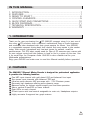
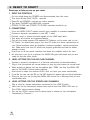
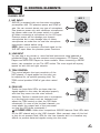
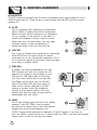
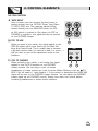
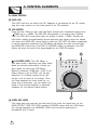
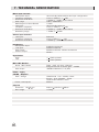
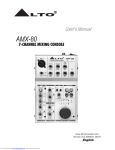
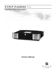
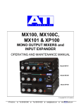
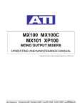
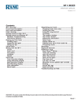
R
LTO
User's Manual
AMX-80
7-CHANNEL MIXING CONSOLE
www.altoproaudio.com
Version 2.0 MARCH 2007
English
IMPORTANT SAFETY INSTRUCTION
CAUTION
RISK OF ELECTRIC SHOCK
DO NOT OPEN
TO REDUCE THE RISK OF ELECTRIC SHOCK
PLEASE DO NOT REMOVE THE COVER OR
THE BACK PANEL OF THIS EQUIPMENT.
THERE ARE NO PARTS NEEDED BY USER
INSIDE THE EQUIPMENT. FOR SERVICE,
PLEASE CONTACT QUALIFIED SERVICE
CENTERS.
WARNING
To reduce the risk of electric shock
and fire, do not expose this equipment
to moisture or rain.
Dispose of this product should
not be placed in municipal waste
and should be separate collection.
11. Move this Equipment only with a cart,
stand, tripod, or bracket,
This symbol, wherever used, alerts you to the
specified by the
presence of un-insulated and dangerous voltages
manufacturer, or
within the product enclosure. These are voltages that
sold with the
may be sufficient to constitute the risk of electric
Equipment. When
shock or death.
a cart is used, use
This symbol, wherever used, alerts you to
caution when
important operating and maintenance instructions.
moving the cart /
Please read.
equipment
Protective Ground Terminal
combination to
AC mains (Alternating Current)
avoid possible
Hazardous Live Terminal
injury from tip-over.
ON: Denotes the product is turned on.
12. Permanent hearing loss may be caused by
OFF: Denotes the product is turned off.
exposure to \ extremely high noise levels.
CAUTION
The US. Government's Occupational Safety
Describes precautions that should be observed to
and Health Administration (OSHA) has
prevent damage to the product.
specified the permissible exposure to noise
1. Read this Manual carefully before operation.
level.
2. Keep this Manual in a safe place.
These are shown in the following chart:
3. Be aware of all warnings reported
with this symbol.
HOURS X DAY SPL EXAMPLE
4. Keep this Equipment away from water and
90 Small gig
8
moisture.
92 train
6
5. Clean it only with dry cloth. Do not use
95 Subway train
4
solvent or other chemicals.
97 High level desktop monitors
3
6. Do not damp or cover any cooling opening.
100 Classic music concert
2
Install the equipment only in accordance with
the Manufacturer's instructions.
102
1,5
105
1
7. Power Cords are designed for your safety. Do
110
0,5
not remove Ground connections! If the plug
does not fit your AC outlet, seek advice from
0,25 or less 115 Rock concert
a qualified electrician. Protect the power
According to OSHA, an exposure to high SPL in
cord and plug from any physical stress to
excess of these limits may result in the loss of
avoid risk of electric shock. Do not place
heat. To avoid the potential damage of heat, it is
heavy objects on the power cord. This could
cause electric shock or fire.
recommended that Personnel exposed to
equipment capable of generating high SPL use
8. Unplug this equipment when unused for long
hearing protection while such equipment is
periods of time or during a storm.
under operation.
9. Refer all service to qualified service personnel
The apparatus shall be connected to a mains
only. Do not perform any servicing other than
those instructions contained within the
socket outlet with a protective earthing
User's Manual.
connection.
10. To prevent fire and damage to the product,
use only the recommended fuse type as
indicated in this manual. Do not short-circuit
the fuse holder. Before replacing the fuse,
make sure that the product is OFF and
disconnected from the AC outlet.
The mains plug or an appliance coupler is used
as the disconnect device, the disconnect device
shall remain readily operable.
IN THIS MANUAL:
1. INTRODUCTION.....................................................................1
2. FEATURES............................................................................1
3. READY TO START ?................................................................4
4. CONTROL ELEMENTS............................................................5
5. QUICK START AND CONNECTIONS.........................................10
6. BLOCK DIAGRAMS...............................................................11
7. TECHNICAL SPECIFICATION...................................................12
8. WARRANTY .........................................................................13
1. INTRODUCTION
Thank you for your purchasing the LTO AMX-80 compact mixer. It is just one of
the many LTO products that a talented, multinational Team of Audio engineers
and musicians have developed with their great passion for Music. Your AMX-80
is a remarkable compact mixing desk that doesn't find many equals in the market
today. With enough microphone and Line-level inputs for serious, small live
performances, The 2TK input usually used for Tape of CD sources even comes with
its own volume control and this feature is hard to find in a mixer of this size. Use
it for small Gigs, for Computer Audio. AMX-80 is also a flexible tool for your
Multimedia presentations.
Enjoy your AMX-80 and make sure to read this Manual carefully before operation!
2. FEATURES
The AMX-80 7-Channel Mixing Console is designed for professional application.
It provides the following features:
One MIC input channel with gold plated XLR and balanced Line input.
Two stereo input channels with balanced TRS jack.
Ultra-low noise discrete MIC pre-amps with +15V Phantom power.
Extremely high headroom offering extra dynamic range.
Balanced inputs for highest signal integrity and low-noise operation.
Warm, natural 2-band EQ on mono channel.
Peak LEDs on each channel.
2-Track inputs with level control assignable to main mix, Headphone outputs.
Highly accurate 4-segment bar graph meters.
1
HOOK
SMALL GIG HOOKUP DIAGRAM
ACTIVE SPEAKER
UP
MICROPHONE
LTO
MIC 1
AM
R
7-CHANNEL MIXING CONSOLE
1
3
- 80
MAIN
OUTPUT
J.T.
2
LINE IN 2/3
LINE IN 4/5
LEFT (MONO)
LEFT (MONO)
LEFT
RIGHT
RIGHT
RIGHT
BAL OR
UNBAL
LINE IN 1
TRIM
+15dB
0dB
2-TRACK IN/OUT
TAPE
-30dB LINE
44dB MIC
L
HEADPHONE
0
RIGHT
LEFT
0
2TK TO
MIX
2TK TO
PHONES
BAL
EQ
PEAK
HI
12kHz
R
MAX
PHONES
TAPE IN
8
-15
0
+15
8
-
KEYBOARD
PAN
LEFT
L
-20
2/3
+15
+5
CLIP
PWR
BAL
RIGHT
DAT
RIGHT
LEFT
PEAK
-
LEVEL
-
4/5
1
DAT RECORDER
+15
LEVEL
+15
8
+15
8
8
0
R
PEAK
-
TAPE OUT
OUTPUT LEVEL
+15
LEVEL
LOW
80Hz
-15
PHONES
MAIN MIX LEVEL
CD PLAYER
DRUM MACHINE
HOOK
COMPUTER SET-UP DIAGRAM
UP
ACTIVE SPEAKER
MICROPHONE
LTO
MIC 1
2
AM
R
7-CHANNEL MIXING CONSOLE
LINE IN 2/3
LINE IN 4/5
MAIN
OUTPUT
LEFT (MONO)
LEFT (MONO)
LEFT
RIGHT
RIGHT
RIGHT
J.T.
1
3
- 80
BAL OR
UNBAL
LINE IN 1
PHONES
D/I BOX
TRIM
+15dB
0dB
BAL
2TK TO
MIX
2TK TO
PHONES
L
EQ
PEAK
HI
12kHz
R
MAX
PHONES
TAPE IN
8
0
+15
8
-
-15
PAN
LEFT
RIGHT
GUITAR
1
0
+5
CLIP
PWR
R
LINE
IN
LINE
OUT
BAL
MIC
IN
PEAK
-
8
8
+15
LEVEL
-20
RIGHT
LEFT
PEAK
-
L
2/3
+15
TAPE OUT
OUTPUT LEVEL
+15
LEVEL
LOW
80Hz
+15
LEVEL
4/5
-
+15
8
-15
HEADPHONE
0
RIGHT
LEFT
0
2-TRACK IN/OUT
TAPE
-30dB LINE
44dB MIC
MAIN MIX LEVEL
SOUND CARD
DRUM MACHINE
3
3. READY TO START?
Some tips to help you set up your mixer
1. ZERO THE CONTROLS
At this stage leave the POWER cord disconnected from the mixer.
Turn down all the GAIN, LEVEL controls.
Keep EQ and PAN/BAL controls on center position.
Turn down PHONES and MAIN MIX controls.
2TRACK TO MIX and 2TRACK TO PHONE switches should be up.
2. C0NNECTIONS
From the MAIN OUPUT socket connect your amplifier or powered speakers.
Connect a dynamic microphone to the MIC 1 input.
Connect mono or stereo line-level signals to the LINE input jacks.
Turn down all controls as suggested above.
Only at this stage connect the supplied AC Adaptor to the mixer and to the
AC Outlet. You should also plug in into the AC outlet the other components of
your Sound systems such as amplifiers, powered speakers, sound processors,
etc. Make sure that the AC outlet are properly grounded and able to deliver
enough current.
Now turn on all the power switches and leave the amplifier switch for last.
At this point turn up of a quarter the MAIN MIX giant blue knob and you are
ready to set the other levels.
3. LEVEL SETTING FOR THE MIC/LINE CHANNEL
Connect a dynamic microphone or a line-level instrument as described above.
Sing in the microphone at normal volume or play the instrument at normal level.
While singing or playing turn up the relative gain ( TRIM ) so that the PEAK LED
next to the LEVEL control starts blinking.
Now start to raise the channel LEVEL until you hear your noise comfortably.
If you like you can use the EQ on the MIC channel to adjust high and low frequencies.
Now you can turn up the big blue MAIN MIX control for a listening level you are
comfortable with.
4. LEVEL SETTING FOR THE STEREO LINE CHANNELS
Play a mono or stereo instrument connected to the LINE IN jacks.
Now turn up the instrument output level control until the PEAK LED next to
The LEVEL control starts blinking.
Turn up the LEVEL control until is about equal in volume to the microphone.
Connected to Channel 1.
4
SP
OT
L
4. CONTROL ELEMENTS
IG
HT
CHANNEL INPUT
1 MIC INPUT
AMX-80 is equipped with one low-noise microphone
pre-amplifier with 15V phantom power and 50dB of
gain. You can connect almost any type of microphone.
Use phantom power only with condenser microphones
but please make sure the power switch is turned
off before connecting a microphone to the XLR input.
Phantom power will not damage your dynamic
microphones but it may damage tube or ribbon
microphones so make sure to read the microphone
instructions manual before using.
NOTE: Never try to connect a line-level signal to the
XLR MIC input when the phantom power functions.
MIC 1
J.T.
2
1
3
1
BAL OR
UNBAL
2
LINE IN 1
2 LINE INPUT
You can plug in any stereo or mono line-level instrument using balanced or
unbalanced plugs. You can also connect sound processors, CD Players, Tape
Players and MP3-iPOD Players to these sockets. When connecting a MONO
device, just remember to use The LEFT socket. The mono signal will anyway
appear on both left and right outputs.
3 TRIM CONTROL
This control adjusts the input sensitivity of the
MIC1channel. A signal applied to this input can
be adjusted for an optimal operating level. The
TRIM control provides 50dB of gain when raised
fully.
TRIM
+15dB
0dB
-30dB LINE
44dB MIC
3
8
4 PEAK LED
Thanks to these little LEDs you know that the
PEAK
signals applied to the mixer are adjusted properly
4
and that they come into the mixer without
distortion. Perform a sound-check with a microphone
+15
or a line-level instrument such as keyboard and
LEVEL
adjust the TRIM control so that the LED blinks
occasionally ( In case of the line-level channels, you
must adjust the output level of the instrument
so that the LED blinks occasionally ).
A CLOSER LOOK: Unlike other competitors AMX-80 features Peak LEDs both
on the MIC channel and on the LINE channels. Most compact mixer of this kind
in fact do not present Peak LEDs for the Line channels and it is therefore very
difficult to prevent distorted signals coming into the mixer.
5
SP
OT
L
4. CONTROL ELEMENTS
IG
HT
EQUALIZATION
The MIC channel is provided with 2 bands of equalization each one providing for up to
15dB of boost and cut. There will be no signal change with the EQ control in centre
position (0).
5 HI EQ
This is a shelving filter operating on frequencies
above 12kHz. It means that all the frequencies
above this level will be boosted or cut depending
on the rotation of this control. If you want to
reduce the sibilance of human voice or reduce
Tape noise, turn the knob down. You can make
cymbals crispier or add transparency to
vocals and guitar if you turn the knob up.
0
HI
12kHz
5
-15
6 LOW EQ
This is also a shelving filter operating on frequencies
below 80Hz.Turn the control down to reduce
unwanted hum or low frequencies resonance. Turn it
up to add more punch to your bass drums and give
more body to a Bass Guitar.
7 PAN/BAL
It stands for Panoramic/Balance. For the
MIC channel and with the control on (0)
position the signal is sent equally to the
Left and to the Right side of the main
mix. Turn the Control all to the left and
the Signal will be sent only to the left
side of the Main Mix and vice versa. In
case of the stereo channels the BAL
control is pretty much like a balance
control in your home stereo. Turn the
control left and the right channel will be
attenuated and vice versa.
EQ
0
6
LOW
80Hz
-15
+15
PAN
LEFT
+15
RIGHT
BAL
LEFT
RIGHT
7
8
PEAK
8 LEVEL
This is the master level control for the relative
8
channel. If the MIC TRIM is set correctly,
+15
as well as the output level of the instruments
LEVEL
plugged into the line-level channels, the
LEVEL control will be positioned in between (0) and 3 o'clock. If you have to
turn the LEVEL control further up, it means that the TRIM ( and the instruments
output level ) is set too low and vice versa.
6
SP
OT
L
4. CONTROL ELEMENTS
IG
HT
THE TAPE SECTION
9 TAPE INPUT
Here is where you can connect line-level mono or
stereo devices such as DC-DVD Player, Tape Player,
TV, MP3, iPOD, etc. The incoming signals will be
routed directly into the MAIN MIX when the 2TK
to MIX switch is pushed in. But when the 2TK to
PHONES is pushed in, the signal will also be routed
to the PHONES Output.
10 2TK TO MIX
When you push in this switch, the signal applied to the
TAPE IN socket will be sent directly to the Main Mix
large blue Control knob. This is usually used in between
a gig and another when you stop for a beer ( or more )
and you want to give some reproduced music to the
Audience.
L
R
TAPE IN
TAPE OUT
9
TAPE
2TK TO
PHONES
2TK TO
MIX
11 2TK TO PHONES
When pushed in this switch, it will assign the signal
applied to the TAPE IN sockets to the PHONES
10
11
output sockets. You can plug in a pair of stereo
headphones to these sockets or a pair of active Studio Monitors such as LTO
M3A ( You will need a Y type Adapter ). If this switch is depressed the MAIN MIX
signal will be sent to the PHONES output sockets. You can adjust the PHONES
output signal via the PHONES control. Always turn down this control before
connecting headphones or active studio monitors.
11
7
SP
OT
L
4. CONTROL ELEMENTS
IG
HT
The MAIN SECTION
12 PWR LED
This LED will turn on when the AC Adaptor is connected to an AC outlet
and the main switch on the back panel is on ON position
13 LED METER
There are four LEDs for each Left and Right channel with thresholds ranging from
20dBu up to +18dBu. The 0dB LED corresponds to an output level of about
0dB. The CLIP LED comes alive when the output is about +18dBu. Actually we
have built a safety threshold before actual distortion and clipping occur but please
turn down the MAIN MIC control knob so that the CLIP LED only blinks occasionally.
In normal operating conditions the LED Meter will display the main mix level after
the MAIN MIX control but if the 2TK TO PHONES switch is pressed in the LED
Meter will show the level of the signal applied to the TAPE IN sockets.
13
OUTPUT LEVEL
L
-20
0
+5
CLIP
PWR
R
-
+15
8
A CLOSER LOOK: The LED Meter is
your best friend in adjusting the Mixer audio
levels for optimal performance. Usually you
get a good mix when the LED Meter
flashes in between -20dB and +6dB. If the
Meter flashes a lot at PEAK, you will get
distortion. If no Meter activity at all, you
will get a lot of noise at the output. Once
you have adjusted the mixer levels for no
noise and no distortion, you can adjust the
levels of the external amplifier or powered
speakers for the desired overall volume.
12
MAIN MIX LEVEL
14
14 MAIN MIX LEVEL
This large blue knob controls the final level of the main mix signal sent to the
MAIN OUTPUT, TAPE OUT (RCA sockets), PHONES output and the LED Meter.
For optimal operation the MAINMIX LEVEL knob should be positioned in
between(0) and 3 o'clock.
8
SP
OT
L
4. CONTROL ELEMENTS
IG
HT
O
THE OUTPUT CONNECTIONS
AM
R
OLE
15 MAIN OUT
Connecting these Left and Right Output to an
amplifier or a pair of powered speakers. You
may decide to plug in an equalizer or a dynamic
processor in between these outputs and your
amplifier/powered speakers.
- 80
MAIN
OUTPUT
15
LEFT
16 PHONES OUTPUT
The stereo signal at this output is controlled by
the PHONES control. Through this output (via
headphones of powered Studio Monitors) you can
listen either to the Main Mix or to the signal
applied to the TAPE IN sockets depending on the
positions of the 2TR to PHONES switch.
17 TAPE OUT
You can record your entire session into a Tape or
DAT Recorder connected to these outputs. The
level at these sockets will be affected by the MAIN
MIX control.
PHONES
RIGHT
16
L
17
R
REAR PANEL DESCRIPTION
OFF
ON
TAPE OUT
CAUTION
RISK OF ELECTRIC SHOCK
DO NOT OPEN
POWER
RATED POWER
CONSUMPTION: 8W
18
18VAC~
WARNING: SHOCK HAZARD DO NOT OPEN
AVIS: RISQUE DE CHOC ELECTRIQUE NE PAS OUVRIR
19
Connect the supplied AC Adaptor into this socket and then to the AC outlet.
18 POWER ON/OFF SWITCH
This switch is used to turn the main power ON and OFF.
A CLOSER LOOK: some Competitors do not offer a Power switch in similar
models. In such case the mixer will be permanently ON ( if the AC Adapter is
connected to an AC outlet. This may turn out in heat problems, power
consumption and damages to the unit in case of lightening ).
19 AC INPUT CONNECTOR
This connector is used to connect the 18VAC adapter supplied by
Company only.
LTO
9
5. QUICK START AND CONNECTIONS
OK. you have got to this point and you are now in the position to successfully operate
your AMX-80: However, we advise you to read carefully the following section to get
the best out of your AMX-80.
Not paying enough attention to the input signal level, to the routing of the signal and
the assignment of the signal will result in unwanted distortion, a corrupted signal or
no sound at all. So you should follow these procedures before operation:
1. Before connecting microphones or instruments, make sure that the power of all
your systems components including the AMX-80 is turned off. Also, make sure
that all input and output controls are turned down. This will avoid damage to your
speakers and excessive noise.
2. Properly connect all external equipment such as microphone, power amplifier,
speakers etc.
3. Now, turn on the power of any peripheral devices, then connect the 18VAC power
supply to your AMX-80 and to the AC socket.
NOTE: The power amplifier or powered monitors shall be turned ON after the
AMX-80 and OFF before the AMX-80 is turned OFF.
4. Set the output level of your AMX-80 or the connected power amplifier at no
more than 75%.
5. Set the PHONE level at no more than 50%.
6. Set HI, and LOW EQ controls on center position.
7. Set panoramic ( PAN / BAL ) control on center position.
8. While speaking into the microphone ( or playing the instrument ) at normal volume,
adjust the channel level control so that the input PEAK LED light-up only
occasionally; in this way you will maintain good headroom and proper dynamic range.
9. You can shape the tone of each channel by adjusting the equalizer controls as
desired.
10.Now repeat the same sequence for all input channels. The Main LED Meter could
move up into the red section. In this case you can adjust the overall output level
through the MAIN MIX control..
10
6.
6. BLOCK
BLOCK DIAGRAM
DIAGRAM
11
7. TECHNICAL SPECIFICATION
Mono input channels
Microphone input
Frequency response
Distortion (THD & N)
Gain range
SNR (Signal to Noise Rated)
Line input
Frequency response
Distortion (THD & N)
Sensitivity range
electronically balanced discrete input configuration
10Hz to 150kHz, +/ 1dB
0.005% @ +4dBu, 20 Hz-20kHz
0dB to 44dB (MIC)
115dB
electronically balanced
10Hz to 150kHz, +/ 1dB
0.005% @ +4dBu, 20 Hz-20kHz
+15dBu to 30dBu
Stereo input channels
Line input
Frequency response
Distortion (THD & N)
Balanced
10Hz to 55kHz, +/ 1dB
0.005% @ +4dBu, 20 Hz-20kHz
Impedances
Microphone input
Line input
Main output
Phones output
2.66kOhm balanced
20kOhm balanced
240Ohm (balanced) 120Ohm (unbalanced)
25Ohm
Equalization
High
Low
+/ 15dB @12kHz
+/ 15dB @80kHz
Main Mix Section
Noise (Bus Noise)
Max output
Power supply
(AC/AC Adaptor)
Main voltage
Power consumption
Physical
Dimension (W D H)
Net weight
12
Fader 0dB, all input channels
assigned and set to UNITY gain: -106dBr
+22dBu unbalanced, 1/4" jacks
USA/Canada 100~120VAC, 60Hz
Europe 210~230VAC, 50Hz
UK/Australia 240VAC, 50Hz
8Watts
204mm 126.5mm 38mm
0.74Kg
8. WARRANTY
1. WARRANTY REGISTRATION CARD
To obtain Warranty Service, the buyer should first fill out and return the enclosed
Warranty Registration Card within 10 days of the Purchase Date.
All the information presented in this Warranty Registration Card gives the
manufacturer a better understanding of the sales status, so as to purport a
more effective and efficient after-sales warranty service. Please fill out all the
information carefully and genuinely, miswriting or absence of this card will void
your warranty service.
2. RETURN NOTICE
2.1 In case of return for any warranty service, please make sure that the
product is well packed in its original shipping carton, and it can protect your
unit from any other extra damage.
2.2 Please provide a copy of your sales receipt or other proof of purchase with
the returned machine, and give detail information about your return address
and contact telephone number.
2.3 A brief description of the defect will be appreciated.
2.4 Please prepay all the costs involved in the return shipping, handling and
insurance.
3. TERMS AND CONDITIONS
3.1 LTO warrants that this product will be free from any defects in materials
and/or workmanship for a period of 1 year from the purchase date if you
have completed the Warranty Registration Card in time.
3.2 The warranty service is only available to the original consumer, who purchased
this product directly from the retail dealer, and it can not be transferred.
3.3 During the warranty service, LTO may repair or replace this product at its
own option at no charge to you for parts or for labor in accordance with the
right side of this limited warranty.
3.4 This warranty does not apply to the damages to this product that occurred
as the following conditions:
Instead of operating in accordance with the user's manual thoroughly, any abuse
or misuse of this product.
Normal tear and wear.
The product has been altered or modified in any way.
Damage which may have been caused either directly or indirectly by another
product / force / etc.
Abnormal service or repairing by anyone other than the qualified personnel or
technician.
And in such cases, all the expenses will be charged to the buyer.
3.5 In no event shall LTO be liable for any incidental or consequential damages.
Some states do not allow the exclusion or limitation of incidental or
consequential damages, so the above exclusion or limitation may not apply to
you.
3.6 This warranty gives you the specific rights, and these rights are compatible
with the state laws, you may also have other statutory rights that may vary
from state to state.
13
SEIKAKU TECHNICAL GROUP LIMITED
NO. 1, Lane 17, Sec. 2, Han Shi West Road, Taichung 40151, Taiwan
http://www.altoproaudio.com Tel: 886-4-22313737
email: [email protected] Fax: 886-4-22346757
All rights reserved to ALTO. All features and content might be changed
without prior notice. Any photocopy, translation, or reproduction of part of this
manual without written permission is forbidden. Copyright c 2007 Seikaku Group
NF02625-1.1