1
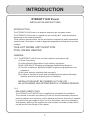
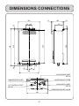
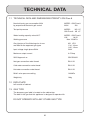
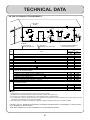
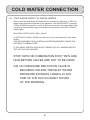
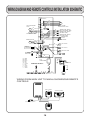
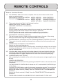
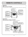
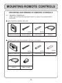
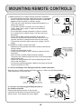
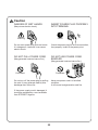
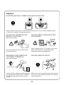
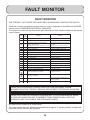
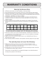
EXTERNAL GAS HOT WATER UNIT
INSTALLATION AND OPERATING
INSTRUCTIONS
MODELS G26 Pure 6
FOR ADVICE, REPAIRS AND
FAST SERVICE
1300 367 565
20637894 (K)
INDEX
INSTALLATION INSTRUCTIONS
PAGE NO.
Introduction
1
Dimensions Connections
2
Exploded Diagram
3
Technical Data
4-6
Gas Connection
7
Cold Water Connection
8
Hot Water Connection
9
Electrical Requirements
9
Wiring Diagram and Remote Controls Installation Schematic
10
Remote Controls
11-12
Mounting Remote Controls
13-15
User Instructions
16-17
Care of THE ETERNITY Hot Water Unit
Hints for Using THE ETERNITY Unit
18
19-23
Fault Monitor
24
Warranty Conditions
25
INTRODUCTION
ETERNITY G26 Pure 6
INSTALLATION INSTRUCTIONS
INTRODUCTION
The ETERNITY G26 Pure 6 is an external electronic gas hot water heater.
The ETERNITY G26 Pure 6 is supplied set at a constant 60℃ outlet temperature
depending on the model purchased.
Three optional remote controls can be provided for complete hot water temperature
selection and if this option is used an approved temperature limiting device must be
installed.
THIS HOT WATER UNIT IS NOT FOR
POOL OR SPA HEATING
GENERAL
1.0.1 The ETERNITY G26 Pure 6 must be installed in accordance with
(1) These instructions;
(2) Uniform Building Regulations Local authority regulations;
(3) AS / NZS 3500.4 "Plumbing and Drainage Heated Water Systems"
(4) The Gas Installations Standard AS 5601 for gas burning appliances and
equipment;
(5) Any other statutory regulation that may apply;
(6) A notice of intention to install shall be lodged with the relevant Municipal
Authority and local Gas Authority prior to installation.
INSTALLATION MUST BE CARRIED OUT ONLY BY
AN AUTHORISED AND APPROPRIATELY LICENSED PERSON.
1.0.2
DELIVERY INSPECTION
The ETERNITY HOT WATER unit is supplied fully assembled for installation.
The customer or installer upon delivery of the unit should immediately remove all
packing materials and inspect the unit for damage and ensure that the unit supplied
is correct for the gas supply to which it is to be connected, report any damage or
discrepancies quoting to the supplier the serial number and model number, which
can be found on the outside of the cabinet.
1
DIMENSIONS CONNECTIONS
350
165
15
122
569
25
585
8
50
575
35
623
13
50
12
84
308
COLD WATER INLET
R3/4 /20
WATER INLET FILTER
CABLE ENTRY POINT
GAS SUPPLY INLET
HOT WATER OUTLET
R3/4 /20
R3/4 /20
PRESSURE RELIEF VALVE
330
2
EXPLODED DIAGRAM
1
8
4
3
9
NOS. PARTS DESCRIPTION
2
5
6
7
3
1
FLUE OUTLET
2
GAS VALVE
3
CIRCUIT BOARD
4
BURNER CASE
5
HOT WATER OUTLET
6
COLD WATER INLET
7
GAS SUPPLY INLET
8
HEAT EXCHANGER
9
WATER VOLUME
PROPORTIONAL VALVE
TECHNICAL DATA
1.1 TECHNICAL DATA AND DIMENSIONS ETERNITY G26 Pure 6
Nominal hourly gas consumption MJ/h
by proportional electronic gas control
MODEL G26 Pure 6
MJ/H
200
Test point pressure
MODEL
NG LP
G26 Pure 6 .65 .67
Water heating capacity raised 40℃
MODEL G26 Pure 6
L/M
16.25
Max 1200kPa
Working pressure
Gas injectors of the following size in mm
are fitted for the approved gas types
Input voltage single phase 50Hz
NG LPG
1.34 1.0mm
1.65 1.2mm
240V
Maximum output current
0.47Amp
SAIG Approval no.
GSCS20021
Inlet gas connection male thread
R3/4 /20
Cold water connection male thread
R3/4 /20
Hot water connection male thread
R3/4 /20
Relief valve pressure setting
1400kPa
Weight dry
18kg
1.2 DATA PLATE
Left outside of cabinet
1.3 GAS TYPE
The temporary gas label is located on the cabinet top.
The label is the gas that this appliance is designed to operate with.
DO NOT OPERATE WITH ANY OTHER GAS TYPE.
4
TECHNICAL DATA
1.4 HEATER DIMENSIONS:
DEPTH
WIDTH
HEIGHT
165mm
350mm
575mm
1.5 WARNING LABELS
Located on the side of the cabinet.
PLEASE READ THESE LABELS CAREFULLY.
1.6 INSTALLATION POSITION
THIS HEATER IS APPROVED FOR OUTDOOR INSTALLATION
ONLY-IT IS NOT SUITABLE FOR INDOOR USE.
Refer AS 5601 for clearance details for flue terminal.
In addition, ensure that the appliance installation position permits easy access for
maintenance and operation.
For further information, please refer to the Gas Fitting Regulations.
1.7 POSITION FOR INSTALLATION
The heater must be installed by using a fixing method sufficient to hold the 18kg
weight of the unit (see the technical sheet for dimensions of mounting brackets and
positions).
5
TECHNICAL DATA
AS 5601 CLEARANCE REQUIREMENTS.
Openable
window
a
T
h
j
n
f
c
I
j
h
j
k
Ref.
M
P
d
P
d
T
g
See note2
LEGEND:
T Flue terminal
I Mechanical air inlet
e
h
Door
k
c
e
Gas meter
Electricity meter or fuse box
g
T
M
b
See note3
Shading indicates prohibited
areas for flue terminals
Minimum clearances
(mm)
Natural
Fan
draft
assisted
Item
a
Below eaves, balconies and other projections:
Appliances up to 50MJ/h input
300
200
Appliances over 50MJ/h input
500
300
b
From the ground, above a balcony or other surface
300
300
c
From a return wall or external corner
500
300
d
From a gas meter(M) (see 4.7.11 for vent terminal location of regulator)
1000
1000
e
From an electricity meter or fuse box (P)
500
500
f
From a drain pipe or soil pipe
150
75
g
Horizontally from any building structure or obstruction facing a terminal
500
500
h
From any other flue terminal, cowl, or combustion air intake
500
300
j
Horizontally from an openable window, door, non-mechanical air inlet, or any other opening into a building with the
exception of sub-floor ventilation:
Appliances up to 150MJ/h input
500
300
Appliances over 150MJ/h input up to 200MJ/h input
1500
300
Appliances over 200MJ/h input up to 250MJ/h input
1500
500
Appliances over 250MJ/h input
1500
1500
All fan-assisted flue appliances, in the direction of discharge
1500
k
From a mechanical air inlet, including a spa blower
1500
1000
n
Vertically below an openable window, non-mechanical air inlet, or any other opening into a building with the exception
of sub-floor ventilation:
Space heaters up to 50MJ/h input
150
150
Other appliances up to 50MJ/h input
500
500
Appliances over 50MJ/h input and up to 150MJ/h input
1000
1000
Appliances over 150MJ/h input
1500
1500
Unless appliance is certified for closer installation
NOTES:
1 All distances are measured to the nearest part of the terminal.
2 Prohibited area below electricity meter or fuse box extends to ground level.
3 See Clause 5.13.6.6 for restrictions on a flue terminal under a covered area.
4 See Appendix J, Figures J2(a) and J3(a), for clearances required from a flue terminal to an LP Gas cylinder, A flue
terminal is considered to be a source of ignition.
5 For appliances not addressed above acceptance should be obtained from the technical regulator
FIGURE 5.3(in part) MINIMUM CLEARANCES REQUIRED FOR BALANCED FLUE TERMINALS, FAN-ASSISTED
FLUE TERMINALS, ROOM-SEALED
APPLIANCE TERMINALS OR THE TERMINALS OF OUTDOOR APPLIANCES
6
GAS CONNECTION
1.8 GAS CONNECTION
(1) Fit a union to the water heater gas inlet for easy connection and removal. The thread
diameter is R3/4 /20
THIS DOES NOT INDICATE THE SIZE OF THE GAS SUPPLY refer to AS 5601
for guidance on pipe sizing.
(2) Fit an AGA approved isolating gas cock in the supply line adjacent to the water heater
gas connection.
(3) Ensure that the supply pipe and the gas pressure regulator (LPG or Natural Gas) has
sufficient flow capacity for this and other appliances connected to the fitting line.
(4) For LPG appliances ensure that gas cylinders are of sufficient size. The water heater
alone will require a regulator of 4KG per hour capacity.
(5) Before connecting the appliance to the gas service purge any debris or air from the gas
service. Venting of purged gas shall be an area free of sources of ignition.
Close the isolating gas cock prior to connection of the appliance.
(6) After connection check all joints for leaks with an approved leak tester.
Refer to AS 5601 Installations Standard for pipe sizing details. For your assistance we
have included the following pipe sizing from AS 5601 for copper tube using Natural Gas.
NOMINAL PIPE
SIZE IN mm
STRAIGHT LENGTH
OF PIPE METRES
HOURLY RATE
IN MJ/h
13
4
43.0
18
4
82.2
20
4
142.0
25
4
313.0
THE ETERNITY G26 Pure 6 REQUIRES A MINIMUM OF 200 MJ/h FOR
THE CUSTOMER TO GET THE FULL PERFORMANCE BENEFIT.
SERVICE CALLS ARE CHARGEABLE FOR
UNITS WITH INCORRECT GAS PIPE SIZES.
7
COLD WATER CONNECTION
1.9 COLD WATER SUPPLY TO WATER HEATER
Refer to the Technical Sheet for the position of connections. Minimum of R3/4 /20
copper tube should be connected to the appliance. The WATER INLET connection
is R3/4 /20 BSP and requires a union to allow for removal of the water heater. Pipe
sizing from the cold water supply should be sized according to local BY LAWS for
water supply.
ISOLATING GATE VALVE or BALL VALVE
A GATE VALVE or BALL VALVE must be used on the cold water inlet to the water
heater.
THIS REQUIREMENT IS AN AUSTRALIA WIDE REQUIREMENT UNDER THE
NATIONAL PLUMBING CODE.
IF THE ABOVE INSTRUCTION IS NOT CARRIED OUT ALL WARRANTIES ON
THE UNIT WILL BE INVOIDED.
STOP TAPS OR COMBINATION STOP TAPS AND
NON-RETURN VALVES ARE NOT TO BE USED!
N.B. NO PRESSURE REDUCTION VALVE IS
REQUIRED UNLESS THE INLET WATER
PRESSURE EXCEEDS 1400kPa AT ANY
TIME OF THE DAY. EG EARLY HOURS
OF THE MORNING.
8
HOT WATER CONNECTION
2.0 Refer to Technical sheet for position of connection. The outlet connection is R3/4 /20
male thread and requires an isolating union to allow for removal of the unit.
2.1 Install the hot water supply line to the unit in a minimum of R3/4 /20 copper tube.
For units set at 50℃ this must be a minimum of Four(4) Metres to the first outlet.
Refer to the instructions supplied with these models for full details.
2.2 Keep the pipe lengths to a minimum and make sure that the pipework is well insulated,
as correct performance of the appliance is dependent on properly insulated pipework.
2.3 DO NOT FIT ANY VALVES OR RESTRICTORS TO THE OUTLET OF THE WATER
HEATER.
2.4 DO NOT FIT ANY OBSTRUCTION TO THE PRESSURE RELIEF LOCATED ON THE
HOT WATER OUTLET CONNECTION.
BEFORE TURNING ON THE POWER SUPPLY TO THE WATER HEATER.
2.5 After purging the air from the system using the hot water supply taps, remove the water
inlet strainer located on the cold water supply inlet connection.
Remove any debris from the filter and replace. When replacing the filter do not over
tighten the "O"ring seal.
TESTING THE WATER HEATER AFTER INSTALLATION IS COMPLETED.
Turn on power supply to the heater and allow approximately 30 seconds for the computer
to perform a safety check on the CHOFU GK2621K.
Open a hot water tap and check the temperature of the hot water supplied.
IF THE UNIT FAILS TO OPERATE, CONSULT THE FAULT MONITOR ON PAGE 24.
ELECTRICAL REQUIREMENTS
3.0 The appliance is equipped with a three pinned earthed plug to be connected to a 220240V 50Hz power supply. The electrical rating of the appliance is 0.47Amp.
3.1 The appliance requires a 240V 50Hz weatherproof power outlet installed in a protected
position adjacent to the appliance.
3.3 IMPORTANT: The appliance should always be disconnected from the power supply
before any maintenance is carried out.
9
WIRING DIAGRAM AND REMOTE CONTROLS INSTALLATION SCHEMATIC
OFF ON
1
2
3
4
5
6
7
8
DIP SWITCH
R
1
2
MIN.
MIN MAX
GAS PROPORTIONAL
VALVE
BK
P
O
MIN.
W
WATER VOLUME
PROPORTIONAL VALVE
GC-140
1
W
W
TEMPERATURE SENSOR
(HEAT EXCHANGER TEMP.)
TEMPERATURE SENSOR
(INCOMING TEMP.)
W
W
TEMPERATURE SENSOR
(OUTGOING TEMP.)
W
W
2
R
R
WATER FLOW SENSOR
BL
3
W
Y
BL
W
TEMPERATURE
CUTOUT
Y
W
COMBUSTION FAN
FLAME SENSOR
R
Y
W
REMOTE
CONTROLLER
Y
G
10
GY
GY
R
BK
W
BL
BL
4
O
BL
GAS VALVE 2
Y
GY
GY
O
5
GAS VALVE 1
9
Y
IGNITOR
Y
BK
BK
SPARK
ELECTRODE
BK
BK
Y
Y
Y
Y
HI-TEMP FUSE
BK
8
G
W : White
BK : Black
BR : Brown
BL : Blue
GY : Grey
O : Orange
R : Red
G : Green
P : Purple
Y : Yellow
MAIN GAS VALVE
6
W
AUTO
TRANSFORMER
11
G
12
THERMOSTAT FOR FREEZE
PROTECTION HEATERS
SURGE
PROTECTOR
FUSE
(5A)
BK
BL
G
WW
W
W
W
W
W
W
W
W
BL
BR
FREEZE PROTECTION HEATERS
AC240V
WIRING FROM MAIN UNIT TO MAIN & SHOWER/SUB REMOTE
CONTROLS
MAIN CONTROL
SHOWER CONTROL
240volt POWER SUPPLY
SUB CONTROL
(ENSUITE)
10
REMOTE CONTROLS
Refer to Technical Sheets
4.0
The ETERNITY G26 Pure 6 comes complete, with one, two or three remote control
panels, as optional extras.
ONE REMOTE CONTROLS SYSTEM MODEL CMR-2251
MAIN CONTROLS
TWO OR THREE REMOTE
MODEL CMR-2251
MAIN CONTROLS
CONTROLS SYSTEM MODEL YST-2251
SHOWER CONTROLS
MODEL YST-2251S ENSUITE CONTROLS
4.1
These controls are to be fitted in the following locations:
*MAIN CONTROLS - kitchen or laundry
*SHOWER CONTROLS - main bathroom
IMPORTANT
DO NOT locate the remote controls where they may come into contact with water.
DO NOT position the remote controls in the vicinity of chemicals.
DO NOT position the remote controls over a cooker, grill oven or toaster.
DO NOT position the remote controls where materials may spill onto them.
4.2
MAIN REMOTE CONTROLS CMR-2251
The main remote controls is fitted using the mounting holes in the rear of the casing.
Wiring is from the rear using the wiring hole provided in the casing.
4.3
SHOWER REMOTE CONTROLS YST-2251 & ENSUITE REMOTE CONTROL YST-2251S
These controls must be wired from the rear, leave sufficient wire for disconnection and
removal.
4.4
CONNECTION OF WIRING TO THE ETERNITY
Remove the front cover from the unit.
Install the wiring to the ETERNITY G26 Pure 6 by concealing the wiring in the wall cavity.
Install the wiring into the cabinet through the wiring access adjacent to the power cable,
see the Technical Sheet.
4.5
Using the cable clamps provided on the plate adjacent to the terminal block attach the
wiring to the plate. Then attach the wires to the terminals for the remote controls. See
wiring diagram previous page. Replace the front cover and connect the power plug.
4.6
COMMISSIONING AND TESTING
After completing the installation of the unit, turn the water, power and gas supplies on to
the unit.
CONTROLS OPERATION
Turn the main remote controls ON by pressing the ON/OFF switch on the controls to the
ON position.
The MAIN REMOTE CONTROLS will indicate the 42℃ and the MAIN CONTROLS light
will be alight.
Using the UP/DOWN buttons select the hot water temperature required. Turn on the hot
water supply tap. The burner light glowing will indicate that hot water is being supplied.
Move to the shower controls (if fitted). Press the TRANSFER BUTTON and repeat the
procedure.
Move to the Ensuite controls (if fitted). Press the TRANSFER BUTTON and repeat the
procedure.
THERE ARE NO MINOR ADJUSTMENTS THAT CAN BE MADE TO THE UNIT.
11
REMOTE CONTROLS
CMR-2251
(Main remote Controller)
This remote controller is intended to be used in the kitchen, laundry room or utility area.
Digital Monitor
Indicates the selected
water temperature.
Error messages flash in
the event of a failure.
ON Indicator
Indicates power is on to
the system.
Flame Logo Indicator
Indicates that a hot water
faucet is open and that
control of the temperature
is taken at another
controller.
ON/OFF Button
Power switch to operate
this control.
UP/DOWN Button
Increase or decrease the
desired water temperature.
PRIORITY Indicator
Indicates this controller
has priority control over
the other controller.
YST-2251/S
(Bath remote controller / Ensuite)
This remote controller is intended for installation in the bathroom.
Flame Logo Indicator
Indicates that a hot water
faucet is open and that
control of the temperature
is taken at another
controller.
PRIORITY Indicator
Indicates this controller
has priority control over
the other controller.
ON Indicator
Indicates power is on to
the system.
ON/OFF Button
Power switch to operate
this control.
Digital Monitor
Indicates the selected
water temperature.
Error messages flash in
the event of a failure.
UP/DOWN Button
Increase or decrease the
desired water temperature.
12
PRIORITY Button
Priority button to set the
water temperature on
Bath remote controller.
MOUNTING ROMOTE CONTROLS
MOUNTING AND WIRING OF REMOTE CONTROLS
4.7
REMOTE CONTROLS
OPEN THE CARTON BOX AND MAKE SURE TO CHECK FOLLOWING PARTS
PROVIDED.
● MAIN CONTROLS MODEL CMR 2251
2PCS
REMOTE CONTROLS
WOOD SCREW
2PCS
CURL PLUG
WIRING
● SHOWER / SUB CONTROLS MODEL YST-2251 / YST-2251S
2PCS
REMOTE CONTROLS
WOOD SCREW
WIRING
CABLE CLAMP
13
2PCS
CURL PLUG
2PCS
CONNECTOR
MOUNTING REMOTE CONTROLS
1) Safety precautions on Main remote controller installation.
• Connect remote controller cable after heater is unplugged.
• Never install Main remote controller above a combustion
appliance like hot plate or a kitchen range.
• The heat will cause electrical component problems, or
deform the exterior.
• Install Main remote controller out of the reach of
steam, water drop, spray of water from tea kettle,
or electrical pot.
• Do not put Main remote controller in direct sunshine.
• It is convenient to install it where it will be used most
frequently.
• Do not install Main remote controller at the place
where any commercial chemicals like ammonia, sulfur,
chlorine, ethylenic compound and acids etc are used.
• The remote controller cables carry low voltage, 12VDC
digital.
2) Installation of Main remote controller.
• Detach the fitting bracket from Main remote controller by
sliding it down.
• Attach the fitting plate to wall.
• Install conduit inside of wall in advance and secure the
wiring box.
• Pass remote controller cables through conduit.
Then pass the cables through the hole of the fitting bracket
and pull them out.
• Attach the fitting bracket with screws adjusting the screw
hole to the wiring box.
• Connect the remote controller cables to the terminal for the
remote controller of PCB.
Chemicals
Do Not
Remote controller
Remote controller
fitting bracket
In case of installing of the fitting bracket for remote controller.
Align the slots of Main remote controller's back to 4 hooks on the fitting bracket.
Then slide them on from the top.
Slot
Remote controller
fitting bracket
Screw
Hook
Terminal
Hole for wiring
In case you are not using the fitting bracket of
the remote controller.
Detach right-and-left covers of the remote
controller and fix them to the wall directly with
wood screws. Then attach the covers again.
Remote controller
cables
Cover
Wood screw
Cover
14
MOUNTING REMOTE CONTROLS
1) Safety precautions on Bath remote controller / Ensuite installation.
• Before remote controller installation, check the hole position considering wall stud location.
• Note : Do not dismantle the remote controller due to water-proof design.
• Do not install remote controller where water will contact the remote controller directly.
• The remote controller cables carry low voltage, 12VDC digital.
2) Installation of Bath remote controller / Ensuite.
• Drill a hole (more than dia about 12mm) in a wall for the remote controller cables.
• After passing the remote controller cables through the hole, remove the packing's back
paper of remote controller. Then attach the remote controller to the wall.
• Detach both end covers of remote controller and fix the remote controller to the wall with
wood screws(2pcs) in the screw holes provided. Do not tighten the screws excessively,
as the screw hole may be damaged. In case of mounting the remote controller on tile,
cement or mortar, use an expansion bolt.
Remote controller cables
Expansion bolt
Wood screw
Remote controller
packing
Cover
Remote controller
cables
Cover
15
USER INSTRUCTIONS
Operation of Main / Bath remote controller / Ensuite.
Please read these instructions carefully before using this appliance.
1. Turn on the ON/OFF button. (refer to page 12.)
2. The temperature display will illuminate at 42℃.
3. The priority indicator will illuminate.
4. Select hot water temperature by pushing UP/DOWN button (
or
) on the controller.
5. Turn on the hot water faucet. Flame logo indicator will illuminate after a short delay.
This indicator will remain illuminated until the hot water faucet is turned off.
6. The hot water temperature can be altered at any time during the operation by pushing
UP/DOWN button ( or ) located on the controller.
or
PRIORITY control. (change)
The temperature can only be controlled by the remote controller which has the priority indication.
Priority button is only located on the Bath remote controller / Ensuite.
When the priority switch is turned on, priority control over the water temperature is changed
voluntarily.
Warning
Do not turn off the water heater or change the water temperature while someone is
bathing or washing. That may result in scalds or burns.
• In case of installation of both a Main remote controller and a Bath remote controller / Ensuite
with priority button ON, when pushing priority button on Bath remote controller / Ensuite, the
hot water temperature will read 42℃.
• In case of installation for Bath remote controller only, when pushing priority button on it, hot
water temperature will read 42℃.
• The priority mode of YST-2251/YST-2251S can't accept ON/OFF during the operation.
It doesn't matter whether the operation is working or not.
Please operate it after closing the tap.
16
HINTS FOR USING REMOTE CONTROLS
FOR SAFETY AND ENERGY SAVINGS
1. Set the MAIN CONTROL to 42℃ for normal household use and to prevent small children
from scalding.
2. For the dishwasher set the MAIN CONTROL to 60℃ or the temperature in the manufacturer's
instructions.
3. For showering use settings between 37℃-39℃ and no cold water will be needed to be mixed,
and if other hot or cold water taps are used the temperature will be maintained.
THE TEMPERATURE WILL INCREASE BY 1℃ WITH EACH PRESS OF
THE UP/DOWN BUTTONS. THE TEMPERATURE CAN BE ADJUSTED
CONTINUOUSLY BY KEEPING THE BUTTON PRESSED. OVER 50℃
UP TO 60℃, THE TEMPERATURE IS CONTROLLED BY 5℃ NOTCH.
PLEASE NOTE ABOVE 50℃ SCALDING CAN OCCUR WITHIN SECONDS
4. The MAIN REMOTE CONTROL is left switched on at all times for operation.
5. The MAIN REMOTE CONTROL is left switched on at all times and then change can be
made to the operation temperature at any time during operation of hot water taps.
17
CARE OF THE ETERNITY HOT WATER UNIT
1. DO NOT HANG WASHING OR OTHER MATERIALS ADJACENT TO THE UNIT.
2. DO NOT STORE INFLAMMABLE MATERIALS WITHIN 2 METERS OF THE UNIT.
3. DO NOT TOUCH THE FLUE OUTLET OF THE UNIT DURING OR IMMEDIATELY AFTER
OPERATION.
4. IF ANY GAS SMELL COMES FROM THE UNIT, DO
NOT USE NAKED FLAMES
TO TEST FOR GAS LEAKS.
5. TURN
OFF THE GAS SUPPLY AND POWER AND CONTACT YOUR GAS
SUPPLY COMPANY.
CLOSE
6. IF A POWER FAILURE OCCURS THE REMOTE CONTROLS WILL NOT FUNCTION AND
THE ETERNITY UNIT WILL NOT SUPPLY HOT WATER UNTIL POWER IS RESTORED.
PLEASE NOTE
WHEN POWER IS RESTORED THE REMOTE CONTROLS WILL
RESET AT 42℃ AS A SAFE TEMPERATURE.
18
HINTS FOR USING THE ETERNITY UNIT
POINTS NEEDED FOR YOUR SPECIAL ATTENTION
Danger
NO INSTALLATION INDOORS
(May cause oxygen deficiency accident or incomplete combustion.)
The unit is outdoor installation type. Never install indoor
or in the bathroom. It will be extremely dangerous since it
will cause oxygen deficiency and incomplete combustion.
Prohibited
Warning
WATCH FOR GAS LEAK
(May cause fire.)
No Fire
Prohibited
Close
When gas leak is noticed, stop using the unit immediately and close the gas valve,
then contact the shop you bought the unit from or the gas supply company.
CONFIRM TYPE OF GAS AND POWER SUPPLY
(May cause incomplete combustion, explosive ignition or fire.)
GK-2621K EXTERNAL GAS WATER HEATER
SAIG APPROVAL No.
GSCS20021
NAT.G
LPG
200
200
INPUT
MJ/h
44.4
44.4
OUTPUT
kW
0.65
0.67
TEST POINT PRESSURE HIGH kPa
0.10
0.10
TEST POINT PRESSURE LOW kPa
GAS INJECTORS
mm 1.34/1.65 1.0/1.2
WEIGHT
18
18
kg
1200
1200
MAX. WATER PRESSURE
kPa
210
210
MIN. WATER PRESSURE
kPa
WATER HEATING CAPACITY 16.25L/min RAISED 40℃
VOLTAGE 240Volts-50Hz 0.47AMPS
Check
SERIAL No.
Make sure to use the gas type as well as power supply (voltage / frequency) as
indicated on the RATING LABEL located on the cabinet side.
There are Natural Gas and Propane Gas on the GAS TYPE LABEL.
19
Warning
NO DISASSEMBLY, REPAIR OR
MODIFICATION
CAUTION FOR INFLAMMABLE
ITEMS
(May cause fire, electric shock or
other accidents.)
(May cause fire or explosion.)
No Disassemble
Warning
Do not disassemble or modify the units.
Never fail to ask professional assistance
from the dealer you have bought your
unit from for such a case as installation,
removing, auxiliary installation work or
connection to the solar units.
Do not place any inflammable items
such as gasoline or benzene nor use
them around the unit.
Take special care.
NO RUBBER TUBING
(May cause gas leakage or fire.)
Prohibited
Rubber tubing should never be used for
gas piping.
Freeze Prevention.
This unit comes equipped with electric heaters that discourage the water heater
from freezing.
To enable this freeze prevention system to operate there must be an electrical
power supply connected to the unit.
The freeze prevention devices will not operate if the electrical power source is
not connected.
Caution.
The electric heaters are installed inside the water heater only all External Hot
and Cold water supply pipes and fittings connected to the water heater should
be properly insulated.
20
Warning
CAUTION TO PREVENT SCALDING
Caution
Check the water temperature by hand first before using shower.
MEASURE TO BE TAKEN IN CASE OF EMERGENCY
When there is an emergency such as earthquake or fire, apply following procedure.
1. Close the hot water outlet.
Close
2. Close the gas valve and the main water valve.
Close
Close
3. Turn off the main power.
However, in case of gas leakage, first close the gas
valve then wait for the leaked gas to disperse then
turn off the main power supply.
Pull
No wet hand
4. Contact the dealer from whom you bought the unit.
21
Caution
DANGER OF WET HANDS
INSERT POWER PLUG PROPERLY
INTO TERMINAL
(May cause electric shock.)
Warning
Check
Do not touch power plug with wet hands.
It is dangerous, because it can cause
electric shock.
Check the power plug for dust accumulation,
then properly insert to the power point.
DO NOT PULL POWER CORD
DO NOT USE POWER CORD
BUNDLED
(May generate heat and cause fire.)
(May generate heat and cause fire.)
Prohibited
Prohibited
Do not turn off the power plug by pulling
the cord. It may generate heat by wire
breakage then cause fire.
If the power supply cord is damaged, it
should be replaced by a cord available
from ETERNITY Agents.
22
Never use power cord in a bundled
condition.
It will cause heat generation and fire.
Caution
CONFIRM IGNITION, COMBUSTION AND EXTINCTION
Check
Please always check ignition, combustion and extinction of the unit by the operation lamp
of the main or shower / sub remote controls.
DO NOT PUT WATER ON THE
REMOTE CONTROLS
DO NOT INSTALL NEAR ELECTRIC
APPLIANCES
(May cause failure.)
Check
Check
Do not put water on the remote controls.
It will cause failure.
MEASURE TO BE TAKEN FOR
LIGHTNING POSSIBILITY
When installed near to TV or radio, it may cause
picture disturbance or sound disturbance.
Install away from those appliances.
SECURE SERVICE SPACE
(May cause failure.)
Pull
No wet hand
Instant overflow voltage caused by lightning
can damage the electronic parts. Therefore,
turn off the main power when you have
thunder.
Check
Make sure to secure good enough space around
the unit to ensure space necessary for checking
and maintenance.
23
FAULT MONITOR
FAULT MONITOR
THE ETERNITY HOT WATER UNIT HAS A SELF DIAGNOSING FUNCTION FOR FAULTS.
When the unit does not operate correctly an error code is displayed on the MAIN and SHOWER
remote controls TEMPERATURE DISPLAY INDICATOR.
The cause of the fault can be determined after checking the fault numbers display on the remote
control display.
Error Number
of
Code Flashes
Problem
Remedy
-
-
Nothing operates.
000
-
Power recovery detection.
001
6
During power failure, remote controller
wiring is disconnected.
111
1
Gas burner fails to ignite.
Check gas supply.
121
3
Loss of combustion.
Check gas supply and pressure.
141
4
Temperature cutout activated.
Call service center.
321
5
Outgoing temperature sensor wire breakage. Call service center.
331
510
10
16
Heat exchanger temperature sensor wire breakage. Call service center.
Main gas valve failure.
Call service center.
511
17
Gas valve failure.
Call service center.
611
7
Combustion fan failure.
Call service center.
651
9
Water volume proportional valve failure.
Call service center.
721
2
False flame detection.
Call service center.
733
13
Number of connected units discrepancy.
Call service center.
734
14
PCB failure.
Call service center.
735
15
Cascade communication failure.
Call service center.
740
750
740
750
760
-
After power on, nothing operates, but the
error code displays in 1 minute.
Call service center.
8
Communication failure between remote
controllers and PCB.
Turn off power and turn on again.
990
12
Air supply or exhaust blockage failure.
Check that nothing is blocking the air
intake or exhaust.
LC
-
Scale build-up (in heat exchanger) failure.
Call service center.
Call service center.
Check power faillure.
(Alarm record can be indicated in calling mode.)
Turn off the hot water faucets and turn
on again.
(only applies when using remote controller before power failre.) (Alarm record can be indicated in calling mode.)
PLEASE NOTE REPLACENT POWER CORD FOR THIS APPLIANCE CAN BE
OBTAINED FROM THE ETERNITY SERVICE DEPARTMENT TELEPHONE 1300367565
PLEASE NOTE ONLY AUTHORISED PERSONS ARE TO PERFORM SERVICE WORK
ON THIS APPLIANCE FAILURE TO OBSERVE THIS CONDITION WILL VOID THE
WARRANTY AND COULD MAKE THE APPLIANCE UNSAFE.
SCHEDULED SERVICE PERIODS
This water heater requires scheduled maintenance at regular 12 monthly periods to obtain the
maximum service life and safe operation.
24
WARRANTY CONDITIONS
Eternity Continuous Flow
1. All Eternity water heaters must be installed by a Licensed installer.
2. Only Authorised personnel must Install, Commission or Service Eternity water heaters.
3. All Eternity water heaters must be installed in accordance with Manufacturer's Installation
Instructions and in Accordance with local regulations, municipal building codes and current
AS/NZS3000, AS/NZS3500, AS 3498 and AS5601.
4. If the Eternity water heater has not been installed in accordance with Manufacturer's
Installation Instructions or installed as to be easily accessable for servicing, a service
charge may apply.
5. Where a component may have failed under warranty and is replaced, the component
replaced will only be covered by the warranty for the balance of the appliance warranty
period.
6. Water Quality must be within limits specified in table below.
pH
Sodium
6.5 to 8.5
TDS
(Total Dissolved
Solids)
Chlorides
Up to 150 Up to 600 Up to 300
mg/litre
mg/litre
mg/litre
or ppm
or ppm
or ppm
Iron
Total
Alkalinity Dissolved Hardness
Magnesium (as
CaCO3) (free) CO2
CaCO3
Up to 1
mg/litre
or ppm
Up to 10 Up to 200 Up to 25 Up to 200
mg/litre
mg/litre
mg/litre
mg/litre
or ppm
or ppm
or ppm
or ppm
The warranty will be rendered void in the following circumstances:
1. Failure due to misuse, Acts of God, accidental damage, installation by an installer who is
not unauthorised to install an Eternity water heater or incorrect installation and attempts
to repair Eternity by an unqualified person.
2. Repairs and service carried out by a person who is not a Qualified Service Person or
Authorised Service Agent.
3. Faults caused by incorrect installation, water problems, electricity supply and or gas supply.
The warranty does not cover the following:
4. Subject to any statutory provisions to the contrary, claims for damages to walls,
foundations etc or any other consequential loss caused either directly or indirectly by
leakage from the water heater or any other faults.
5. Warranty does not cover any faults that may arise from connecting to a water source that
is unfiltered such as dams, bores, rivers etc.
Eternity does not accept liability for consequential damage or any incidental expenses
resulting from any breach of the Warranty.
25
Warranty Terms
Eternity Water Heaters are covered by Eternity for any cost of labour and parts in the event of
a component failure due to any defects that may arise either from workmanship and or faulty
material.
The Warranty commences on the date of Installation:
Domestic Appliance
Heat Exchanger
All Other Parts
Commercial Application
Heat Exchanger
All Other Parts
Eternity Product
Parts
10 Years
Labour
Parts
3 Years
3 Years
Labour
3 Years
Eternity Product
Parts
5 Years
Labour
Parts
1 Year
1 Year
Labour
1 Year
Definition of Domestic Use:
1. Units installed in any domestic dwelling.
2. Units installed in any gas boosted solar system in a domestic dwelling.
3. Units used in any household applications.
Definition of Commercial Use:
1. Units supplying kitchen areas used for bulk food preparation.
2. Units used in industrial or bulk heating processors and hydronic heating installations.
3. Units used as bulk central heating systems and flow and return systems.
Please contact your ETERNITY office for full warranty conditions
On 1300 367 565 for all Warranty and Service information.