1
aternit
hot water solutions by
CHRIMSIEN
EXTERNAL GAS HOT WATER UNIT
INSTALLATION AND OPERATING
INSTRUCTIONS
MODELS G16/G20/G26
FOR ADVICE, REPAIRS AND
FAST SERVICE
1300 367 565 20501072(K)
INDEX
INSTALLATION INSTRUCTIONS
PAGE NO.
Introduction
1
Dimensions Connections
2
Exploded Diagram
3
Technical Data
4-5
Gas Connection
6
Cold Water Connection
7
Hot Water Connection
8
Electrical Requirements
8
Remote Controls
9
Remote Controls Wiring Diagram
10
Main Remote Control
11
Shower Remote Control
12
Mounting Remote Controls
13-14
User Instructions
15-17
Care of THE ETERNITY Hot Water Unit
18
Hints for Using THE ETERNITY Unit
19-23
Fault Monitor
24
Warranty Conditions
25
INTRODUCTION
ETERNITY G16/G20/G26
INSTALLATION INSTRUCTIONS
INTRODUCTION
The E I ERNTTY 16/20/26 is an external electronic gas hot water heater.
The ETERNITY 16/20/26 is supplied set at a constant 60°C outlet temperature
depending on the model purchased. Three optional remote controls can be
provided for complete hot water temperature selection and if this option is
used an approved temperature limiting device must be installed.
THIS HOT WATER UNIT IS NOT FOR
POOL OR SPA HEATING
GENERAL
1.0.1 The ETERNITY 16/20/26 must be installed in accordance with
(1) These instructions;
(2) Uniform Building Regulations Local authority regulations;
(3) AS/NZS 3500.4"National Plumbing and Drainage Code, Part 4 Hot Water
Supply Systems",
(4) The Australian Gas Association installation code AS5601 for gas burning
appliances and equipment;
(5) Any other statutory regulation that may apply;
(6) A notice of intention to install shall be lodged with the relevant Municipal
Authority and local Gas Authority prior to installation.
INSTALLATION MUST BE CARRIED OUT ONLY BY
AN AUTHORISED AND APPROPRIATELY LICENSED PERSON.
1.0.2
DELIVERY INSPECTION
The ETERNITY HOT WATER unit is supplied fully assembled for installation.
The customer or installer upon delivery of the unit should immediately remove all
packing materials and inspect the unit for damage and ensure that the unit supplied
is correct for the gas supply to which it is to be connected, report any damage or
discrepancies quoting to the supplier the serial number and model number, which
can be found on the outside of the cabinet.
1
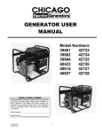
DIMENSIONS CONNECTIONS
Model : 16/20
COLD WATER INLET RP1/2/15
WATER INLET FILTER
CABLE ENTRY POINT
HOT WATER OUTLET 111M=1==All
RP1/2/15
PIFQ)
GAS SUPPLY INLET
RP3/4/20
PRESSURE RELIEF VALVE
330
Model : 26
12
165
15
COLD WATER INLET RP3/4/20
WATER INLET FILTER
CABLE ENTRY POINT
HOT WATER OUTLET 10111===YAN
RP3/4/20
[
GAS SUPPLY INLET
RP3/4/20
pi= Cr 25:
PRESSURE RELIEF VALVE
330
2
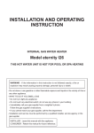
EXPLODED DIAGRAM
Model : 16/20
NOS. PARTS DESCRIPTION
1 FLUE OUTLET
2 GAS VALVE
3 CIRCUIT BOARD
4 BURNER CASE
5 HOT WATER OUTLET
6 COLD WATER INLET
7 GAS SUPPLY INLET
8 HEAT EXCHANGER
Model : 26
0
a
I
U
0
0
III J
/
NOS. PARTS DESCRIPTION
1 FLUE OUTLET
2 GAS VALVE
3 CIRCUIT BOARD
o0 igo
IN
4 BURNER CASE
0
5 HOT WATER OUTLET
MirMaCEMIVACIBil
0
11E111
0
-
0 0
3
6 COLD WATER INLET
7 GAS SUPPLY INLET
8 HEAT EXCHANGER
9 WATER VOLUME
PROPORTIONAL VALVE
2
TECHNICAL DATA
1.1 TECHNICAL DATA AND DIMENSIONS ETERNITY 16 / 20 / 26
Nominal hourly gas consumption MJ/h
by proportional electronic gas control
MODEL 16 20 26
125 160 200
MJ/h
Test point pressure
MODEL NG LP
.40 .40
16
.56 .61
20
26
.68 .70
MODEL 16 20 26
ML/M 10 12.5 16.25
Water heating capacity raised 40°C
Max 1200kPa
Working pressure
MODEL NG LPG MODEL NG LPG
16/20 1.35 1.35 mm 26
1.34 1.0mm
1.65 1.2 mm
1.65 1.65 mm
240V
Gas injectors of the following size in mm
are fitted for the approved gas types Input voltage single phase 50Hz
MODEL 16 20 26
Amp
0.37 0.45 0.47
Maximum output current
SAIG Approval certificate no.
MODEL 16/20 GSCS 20021
26 GSCS 20021
18mm
Inlet gas connection male thread
MODEL 16/20 13mm
26 18mm
MODEL 16/20 13mm
26 18mm
14001cPa
Cold water connection male thread
Hot water connection male thread
Relief valve pressure setting
MODEL 16/20 16kg
26 17kg
Weight dry
1.2 DATA PLATE
Left outside of cabinet
1.3 GAS TYPE
The temporary gas label is located on the cabinet top.
The label is the gas that this appliance is designed to operate with.
DO NOT OPERATE WITH ANY OTHER GAS TYPE.
4
TECHNICAL DATA
1.4
1.5
HEATER DIMENSIONS: DEPTH
WIDTH
HEIGHT
165mm
350mm
575mm
WARNING LABELS
Located on the side of the cabinet.
PLEASE READ THESE LABELS CAREFULLY.
1.6
INSTALLATION POSITION
THIS HEATER IS APPROVED FOR OUTDOOR INSTALLATION
ONLY-IT IS NOT SUITABLE FOR INDOOR USE.
Refer AS5601 for clearance details for flue terminal.
In addition,ensure that the appliance installation position permits easy access for
maintenance and operation.
For further infomation,please refer to the Gas Fitting Regulations.
1.7 POSITION FOR INSTALLATION
The heater must be installed by using a fixing method sufficient to hold the weight of
the unit (see the technical sheet for dimensions of mounting brackets and positions).
5
GAS CONNECTION
1.8 GAS CONNECTION
(1)
Fit a union to the water heater gas inlet for easy connection and removal. The thread
diameter is 18mm.
THIS DOES NOT INDICATE THE SIZE OF THE GAS SUPPLY refer to AS5601 for
guidance on pipe sizing.
(2)
Fit an AGA approved isolating gas cock in the supply line adjacent to the water heater gas
connection.
(3)
Ensure that the supply pipe and the gas pressure regulator(LPG or NaturalGas) has
sufficient flow capacity for this and other appliances connected to the fitting line.
(4)
For LPG appliances ensure that gas cylinders are of sufficient size.The water heater alone
will require a regulator of 4KG per hour capacity.
(5)
Before connecting the appliance to the gas service purge any debris or air from the gas
service. Venting of purged gas shall be an area free of sources of ignition.
Close the isolating gas cock prior to connection of the appliance.
(6)
After connection check all joints for leaks with an approved leak tester.
Refer to AS5601 Installation Code for pipe sizing details. For your assistance we have
included the following pipe sizing from AS5601 for copper tube using Natural Gas.
NOMINAL PIPE
SIZE IN mm
STRAIGHT LENGTH OF
PIPE METRES
HOURLY RATE
IN MJ/h
13
4
43.0
18
4
82.2
20
4
142.0
25
4
313.0
THE ETERNITY 16/20/26 REQUIRES A MINIMUM OF 125/160/200 MJ/h FOR
THE CUSTOMER TO OBTAIN THE FULL PERFORMANCE BENEFIT.
SERVICE CALLS ARE CHARGEABLE FOR
UNITS WITH INCORRECT GAS PIPE SIZES.
6
COLD WATER CONNECTION
1.9 COLD WATER SUPPLY TO WATER HEATER
Refer to the Technical Sheet for the position of connections. Minimum of 13mm for model
16/20 and 18mm for model 26 copper tube should be connected to the appliance . The
WATER INLET connection are 13mm BSP for model 16/20 and 18mm BSP for model
26 and requires a union to allow for removal of the water heater. Pipe sizing from the
cold water supply should be sized according to local BY LAWS for water supply.
ISOLATING GATE VALVE or BALL VALVE
A GATE VALVE or BALL VALVE must be used on the cold water inlet to the water
heater. THIS REQUIREMENT IS AN AUSTRALIA WIDE REQUIREMENT UNDER
THE NATIONAL PLUMBING CODE.
IF THE ABOVE INSTRUCTION IS NOT CARRIED OUT ALL WARRANTIES ON THE
UNIT WILL BE VOIDED.
STOP TAPS OR COMBINATION STOP TAPS AND
NON-RETURN VALVES ARE NOT TO BE USED!
N.B. NO PRESSURE REDUCTION VALVE IS
REQUIRED UNLESS THE INLET WATER
PRESSURE EXCEEDS 1400kPa AT ANY TIME
OF THE DAY. EG EARLY HOURS OF THE
MORNING.
HOT WATER CONNECTION
2.0 Refer to Technical Sheet for the position of connection. The outlet connection is 13mm
for model 16/20 and 18mm for model 26 male thread and requires an isolating union to
allow for removal of the unit.
2.1 Install the hot water supply line to the unit in a minimum of 13mm for model
16/20 and 18mm for model 26 copper tube. for units set at 50°C this must be a
minimum of Four (4) Metres to the first outlet.
2.2 Keep the pipe lengths to a minimum and make sure that the pipework is well
insulated, as correct performance of the appliance is dependent on properly
insulated pipework.
2.3 DO NOT FIT ANY VALVES OR RESTRICTORS TO THE OUTLET OF
THE WATER HEATER.
2.4 DO NOT FIT ANY OBSTRUCTION TO THE PRESSURE RELIEF
LOCATED ON THE HOT WATER OUTLET CONNECTION.
2.5 After purging the air from the system using the hot water supply taps, remove
the water inlet strainer located on the cold water supply inlet connection.
Remove any debris from the filter and replace. When replacing the filter do not
over tighten the"O"ring seal.
ELECTRICAL REQUIREMENTS
3.0 The appliance is equipped with a three pinned earthed plug to be connected to
a 220-240V 50Hz power supply. The electrical rating of the appliance is
0.37/0.45/0.47Amp.for the ETERNITY 16/20/26
3.1 The appliance requires a 240V 50Hz weatherproof power outlet installed in a
protected position adjacent to the appliance.
3.3 IMPORTANT: The appliance should always be disconnected from the power
supply before any maintenance is carried out.
8
REMOTE CONTROLS
Refer to Technical Sheets
4.0 The ETERNITY 16/20/26 comes complete, with one, two or three remote control
panels, as optional extras.
ONE REMOTE CONTROLS SYSTEM
TWO OR THREE REMOTE
CONTROLS SYSTEM
MODEL
MODEL
MODEL
MODEL
CMR-154
CMR-154
YST-84
YST-84S
MAIN CONTROLS
MAIN CONTROLS
SHOWER CONTROLS
ENSUITE CONTROLS
4.1 These controls are to be fitted in the following locations:
* MAIN CONTROLS-kitchen or laundry
* SHOWER CONTROLS-main bathroom
IMPORTANT
DO NOT locate the remote controls where they may come into contact with water.
DO NOT position the remote controls in the vicinity of chemicals.
DO NOT position the remote controls over a cooker, grill oven or toaster.
DO NOT position the remote controls where materials may spill onto them.
4.2 MAIN REMOTE CONTROLS CMR-154
The main remote controls is fitted using the mounting holes in the rear of the casing.
Wiring is from the rear using the wiring hole provided in the casing.
4.3 SHOWER REMOTE CONTROLS YST-84 & ENSUITE REMOTE CONTROL YST-84S
These remote controls have a self adhesive backing plate which can be adhered to any
clean dry surface. These controls must also be wired from the rear, leave sufficient
wire for disconnection and removal.
4.4 CONNECTION OF WIRING TO THE ETERNITY
Remove the front cover from the unit.
Install the wiring to the ETERNITY 16/20/26 main unit using conduit or by concealing
the wires in the wall cavity.
Install the wiring into the cabinet through the wiring access adjacent to the power cable, see
the Technical Sheet.
4.5
Using the cable clamps provided on the plate adjacent to the terminal block attach the
wiring to the plate. Then attach the wires to the terminals for the remote controls. See wiring
diagram next page. Replace the front cover and connect the power plug.
4.6 COMMISSIONING AND TESTING
After completing the installation of the unit, turn the water, power and gas supplies on to the
unit.
CONTROLS OPERATION
Turn the main remote controls ON by pressing the ON/OFF switch on the controls to the
ON position.
The MAIN REMOTE CONTROLS will indicate the 42°C and the MAIN CONTROLS light
will be alight.
Using the UP/DOWN buttons select the hot water temperature required. Turn on the hot
water supply tap. The burner light glowing will indicate that hot water is being supplied.
Move to the shower controls (if fitted). Press the TRANSFER BUTTON and repeat the procedure.
Move to the En Suite controls (if fitted). Press the TRANSFER BUTTON and repeat the procedure.
THERE ARE NO MINOR ADJUSTMENTS THAT CAN BE MADE TO THE UNIT.
9
1 REMOTE CONTROLS WIRING DIAGRAM
WIRING DIAGRAM OF PCB
TURN OFF POWER SUPPLY TO HOT WATER UNIT AND REMOVE
PLUG FROM POWER OUTLET BEFORE REMOVING FRONT COVER OF
HOT WATER UNIT.
ORO.
IN c-1
,[71•
H
,
a
I
TERMINALS FOR
REMOTE CONTROLS
CABLE CLAMP
o
-1aPj=f,
CABLE ENTRY PORT
ANTI-FREEZE HEATER
REMOTE CONTROLS CABLE
WIRING FROM MAIN UNIT TO MAIN & SHOWER/SUB REMOTE
CONTROLS
MAIN CONTROL
SHOWER CONTROL
240volt POWER SUPPLY
SUB CONTROL
(ENSUITE)
10
MAIN REMOTE CONTROLS
MAIN REMOTE CONTROL
CMR-154
16
f
7
\
(
4
5
AL M
•
17 1' 1
17 17 t
PMCILI•ULD
rr
4-1 Fi-1
j
3
2
1
. U6FF
i(
:.:..
...
t. . .1
8
ON
(I)
AM
:o .....°:
?
KITCHEN
CMR- 154
TIME SET
I
9
1a
to el°
dlArrEtrnott
mtealuttatettretcoarigit.*:
hat. artdb.mst t, onvittnet.tere,pkatekter
0.16 1111,t7 frvadcorfrratewta ts-o_
, y
CONTROL
FUNCTION
1
DIGITAL DISPLAY
INDICATES TEMPERATURE & TIME
ERROR CODE WHEN SAFETY DEVICE ON
2
TEMPERATURE CONTROL
ADJUSTS TEMPERATURE BETWEEN 37°C TO 75°C
3
TRANSFER INDICATOR
(GREEN)
INDICATES THIS CONTROL HAS PRIORITY
(CAN ADJUST TEMPERATURE ONLY WHEN)
THE INDICATOR IS ILLUMINATED
4
ON INDICATOR(GREEN)
INDICATES POWER IS ON TO SYSTEM
5
ON/OFF SWITCH
POWER SWITCH TO OPERATE THIS CONTROL
6
COMBUSTION LAMP(RED)
INDICATES A HOT WATER TAP IS BEING OPERATED
7
ALARM LAMP(RED)
FLASHES IN ABNORMAL CONDITION
8
TIME SETTING LAMP(GREEN)
INDICATES THAT THE TIME SETTING IS IN PROCESS
9
TIME SETTING SWITCH
PUSHES WHEN SETTING THE TIME
NOS.
11
SHOWER/SUB REMOTE CONTROLS
SHOWER / SUB REMOTE CONTROLS
YST-84 /YST-84S
16
7
C
[
3-A
3
ALM
(.„
LA
•nrit
rf TI
PM Li LI • LI 11 Pt 1
AM
. . . r---
Ell In
3-B
2
,
TRANSFE1
11
4
5
nn ILM
,
f: - --°11
BATHROOM
YST-84
ON/OFF
o....
O.:':
Fa sa-ery erd pew usg Ice areto rend
te.e.e.
Arremox
11.02.Mry cacd,,,:edetrk,i,
PM,. *arr. xla
(ILLUSTRATION IS FOR YST-84)
NOS. CONTROL
1
DIGITAL DISPLAY
FUNCTION
INDICATES TEMPERATURE & TIME
ERROR CODE WHEN SAFETY DEVICE ON
2 TEMPERATURE CONTROL
ADJUSTS TEMPERATURE BETWEEN 37°C TO 48°C
3 TRANSFER SWITCH
(GREEN)
PUSHES TO SET PRIORITY TO THIS CONTROL
3-A TRANSFER INDICATOR
(GREEN)
INDICATES THIS CONTROL HAS PRIORITY
3-B TRANSFER INDICATOR
(GREEN "T" LAMP)
INDICATES THIS CONTROL HAS PRIORITY
4
ON INDICATOR(GREEN)
INDICATES POWER IS ON TO SYSTEM
5
ON/OFF SWITCH
POWER SWITCH TO OPERATE THIS CONTROL
6 COMBUSTION LAMP(RED)
INDICATES A HOT WATER TAP IS BEING OPERATED
7 ALARM LAMP(RED)
FLASHES IN ABNORMAL CONDITION
12
MOUNTING REMOTE CONTROLS
MOUNTING AND WIRING OF REMOTE CONTROLS
4.7 REMOTE CONTROLS
OPEN THE CARTON BOX AND MAKE SURE TO CHECK FOLLOWING PARTS
PROVIDED.
• MAIN CONTROLS MODEL CMR-154
j------------,,,--\--,_____
V
01"
2PCS
REMOTE CONTROLS
2PCS
WOOD SCREW
CURL PLUG
WIRING
• SHOWER/SUB CONTROLS MODEL YST-84 / YST-84S
-.•''''
1111'11
'11A
04"
cr
2PCS
REMOTE CONTROLS
2PCS
WOOD SCREW
CURL PLUG
(C:1D
4
‘-----__ --_____,-,
WIRING
CABLE CLAMP
13
41111°
2PCS
CONNECTOR
ALTERNATIVES IN MOUNTING REMOTE CONTROLS
IN EITHER OF THE FOLLOWING TWO ALTERNATIVES, YOU ARE TO REMOVE METAL
BRACKET ATTACHED TO THE BACK OF EACH REMOTE BY SLIDING THE BRACKET
FIRMLY DOWN TILL IT IS RELEASED FROM THE NOTCH BY CLICK, THEN PULL IT
OUT.(MAIN CONTROL ONLY)
SINCE SHOWER/SUB CONTROLS WATERPROOFED, PLEASE INSTALL ON DIRECT
MOUNTING.
A. USING THE BRACKET (BEING REMOVED AS ABOVE) AS A FIXTURE:
(REFER THE DIAGRAM BELOW)
1. FIX THE BRACKET TO THE WALL WITH WOOD SCREWS PROVIDED USING ANY
TWO HOLES OUT OF THE SIX HOLES PROVIDED TO THE BRACKET.
2. FASTEN WIRING TO THE TERMINAL BLOCK.
3. FIX THE REMOTE CONTROLS TO THE BRACKET CATCHING THREE NAILS OF THE
BRACKET THROUGH NOTCH AND THEN SLIDING FROM ABOVE FIRM UNTIL IT
CATCHES THE NOTCH IN THE BRACKET AND CLICKS.
REMOTE CONTROL
METAL BRACKET
METAL BRACKET
B. DIRECT MOUNTING
(REFER THE DIAGRAM BELOW)
FRONT COVER
1. REMOVE THE FRONT COVER OF THE
CONTROLS USING SCREWDRIVER
CAREFULLY EASING THROUGH THREE
SLOTS IN TURN PROVIDED AT THE TOP
OF THE CONTROLS.
2. FASTEN WIRING TO THE TERMINAL
BLOCK.(PLEASE SKIP THIS PROCESS IN
CASE OF SHOWER/SUB CONTROLS.)
3. FIX THE REMOTE CONTROLS BASE BY
WOOD SCREWS PROVIDED THROUGH
TWO HOLES AT THE BOTH SIDE OF THE
BASE. THEN FIT THE FRONT COVER IN
PLACE.
14
WOOD SCREW
FRONT COVER
USER INSTRUCTIONS
USER INSTRUCTIONS
PLEASE HAND THIS HANDBOOK TO THE USER AFTER INSTALLATION.
INTRODUCTION:
You have selected the ETERNITY electronic gas hot water unit. The following instructions will
assist you to obtain the best performance from your ETERNITY unit.
OPERATION:
Up to three remote controls are able to be installed with your ETERNITY unit for complete
controls of your hot water.
Please note units without remote control will be set at 60°C or in the case of commercial units 75°C.
OPERATION OF MAIN REMOTE CONTROLS
PLEASE READ THESE INSTRUCTIONS CAREFULLY BEFORE USING THIS APPLIANCE.
1.TURN ON THE ON/OFF SWITCH (REFER PG 11 OF THIS MANUAL).
2. THE TEMPERATURE DISPLAY WILL ILLUMINATE AT 42°C.
3. THE "T" AND ON INDICATORS WILL ILLUMINATE.
4. SELECT HOT WATER TEMPERATURE BY PRESSING UP / DOWN BUTTONS ON THE
CONTROLS.
5. TURN ON A HOT WATER TAP. COMBUSTION INDICATOR WILL ILLUMINATE AFTER
A SHORT DELAY, ON BOTH REMOTE CONTROLS. THESE INDICATORS WILL REMAIN
ILLUMINATED UNTIL THE HOT WATER TAP IS TURNED OFF.
ON
ON
2ui
v
A j
{I
..wON/OFF
`4 27n
V II A 1]
ILTRAI7ER1
• MAIN CONTROL
• SHOWER/SUB CONTROLS
6. THE HOT WATER TEMPERATURE CAN BE ALTERED AT ANY TIME DURING THE
OPERATION BY USING THE UP/DOWN BUTTONS LOCATED ON . THE CONTROLS.
15
USER INSTRUCTIONS
OPERATION OF SHOWER / SUB REMOTE CONTROLS
The SHOWER/SUB CONTROLS overrides the operation of the main control.
Leave the operation switch on the MAIN CONTROL switched ON.
YST-84/84S SHOWER/SUB CONTROLS
1. Press the ON/OFF button after opening the cover on the CONTROLS. See diagram 1 below.
2. Press the TRANSFER BUTTON and the TRANSFER light will illuminate and the
TEMPERATURE DISPLAY will have 42°C displayed. Please refer to page 12 of this
handbook. See diagram 2 below.
3. Using the UP/DOWN BUTTONS select the temperature required. See diagram 3 below.
4.When you have finished using the hot water supply press the TRANSFER BUTTON to return
the controls back to the MAIN CONTROL.
DIAGRAM 1
DIAGRAM 2
DIAGRAM 3
16
HINTS FOR USING REMOTE CONTROLS
FOR SAFETY AND ENERGY SAVINGS
1. Set the MAIN CONTROL to 42°C for normal household use and to prevent small children
from scalding.
2. For the dishwasher set the MAIN CONTROL to 60°C or the temperature in the manufacturer's
instructions.
3. For showering use settings between 37°C-39°C and no cold water will be needed to be mixed,
and if other hot or cold water taps are used the temperature will be maintained.
THE TEMPERATURE WILL INCREASE BY 1°C WITH EACH
PRESS OF THE UP/DOWN BUTTONS. THE TEMPERATURE
CAN BE ADJUSTED CONTINUOUSLY BY KEEPING
THE BUTTON PRESSED. OVER 50°C UP TO 75°C,
THE TEMPERATURE IS CONTROLLED BY 5-°C NOTCH.
PLEASE NOTE ABOVE 50°C SCALDING CAN OCCUR WITHIN SECONDS
4. The MAIN REMOTE CONTROL is left switched on at all times for operation.
5. The MAIN REMOTE CONTROL is left switched on at all times and then change can be made
to the operation temperature at any time during operation of hot water taps.
17
CARE OF THE ETERNITY UNIT
1. DO NOT HANG WASHING OR OTHER MATERIALS ADJACENT TO THE UNIT.
2. DO NOT STORE INFLAMMABLE MATERIALS WITHIN 2 METERS OF THE UNIT.
3. DO NOT TOUCH THE FLUE OUTLET OF THE UNIT DURING OR IMMEDIATELY AFTER
OPERATION.
4. IF ANY GAS SMELL COMES FROM THE UNIT, DO NOT USE NAKED FLAMES
TO TEST FOR GAS LEAKS.
5. TURN OFF THE GAS SUPPLY AND POWER AND CONTACT YOUR
GAS SUPPLY COMPANY.
6. IF A POWER FAILURE OCCURS THE REMOTE CONTROLS WILL NOT FUNCTION AND
THE CHOFU UNIT WILL NOT SUPPLY HOT WATER UNTIL POWER IS RESTORED.
PLEASE NOTE
WHEN POWER IS RESTORED THE REMOTE CONTROLS WILL
RESET AT 42°C AS A SAFE TEMPERATURE.
18
HINTS FOR USING THE ETERNITY UNIT
POINTS NEEDED FOR YOUR SPECIAL ATTENTION
,L Danger
NO INSTALLATION INDOORS
(May cause oxygen deficiency accident or incomplete combustion.)
The unit is outdoor installation type. Never install indoor
or in the bathroom. It will be extremely dangerous since it
will cause oxygen deficiency and incomplete combustion. Prohibited
,AWarning
WATCH FOR GAS LEAK
May cause fire.)
No Fire
Close
Prohibited
When gas leak is noticed, stop using the unit immediately and close the gas valve, then contact
the shop you bought the unit from or the gas supply company.
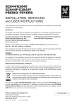
CONFIRM TYPE OF GAS AND POWER SUPPLY
(May cause incomplete combustion, explosive ignition or fire.)
0
Check
ETERNITY G16 EXTERNAL GAS WATER HEATER
SAIL APPROVAL No. GSCS20021
NAT.G
INPUT
M1/11
125
OUTPUT
kW/M1
27.8
TEST POINT PRESSURE HIGH
kPa
0.40
TEST POINT PRESSURE LOW kPa
G103
rnrn
GAS INJECTORS
135/1.65
WEIGHT
kg
ISO
kPa
MAX WATER PRESSURE
1200
MIN. WATER PRESSURE
kPa
260
WATER HEATING CAPACITY 10.01/min RAISED 400
VOLTAGE 240 Volts-50Hz 0.37AMPS
SERIAL No.
0
°
a
5
Safety 8
Certified
n54553
CAN
SAI Global
20541310
ETERNITY G20 EXTERNAL GAS WATER HEATER
SAIG APPROVAL No. GSCS20021
NAT.G
INPUT
M.1/11
160
OUTPUT
kW/h
365
TEST POINT PRESSURE HIGH kPa
0.56
kPa
TEST POINT PRESSURE LOW
0.103
GAS INJECTORS
1,,r11
1.35,1.55
WEIGHT
16.0
kg
MAX WATER PRESSURE
kPa
1200
KN. WATER PRESSURE
kPa
260
WATER HEATING CAPACITY 1 2.51/min RAISED 400
VOLTAGE 240 Volts-SOHz 0.45AMPS
SERIAL No.
Armi
5
VeY,
GaS Safety 8
Certified
AS 4558
SAI Global
20541330
ETERNITY G26 EXTERNAL GAS WATER HEATER
SAIL APPROVAL No. GSCS20021
NAT.G
M.1/11
INPUT
200
OUTPUT
kW/M1
94.4
TEST POINT PRESSURE HIGH
kPa
0.68
TEST POINT PRESSURE LOW
kPa
0.118
rnm
GAS INJECTORS
1.34/1.65
WEIGHT
kg
17.0
MAX WATER PRESSURE
kPa
1200
MIN. WATER PRESSURE kPa
210
WATER HEATING CAPACITY 1 G251./min RAISED 400
VOLTAGE 240 Volts-50Hz 0.47AMPS
SERIAL No.
m
..
,
A
Gas Safely 8
Certified
As 4552
SA1 Global
20541350
Make sure to use the gas type as well as power supply (voltage/frequency) as indicated on the
RATING LABEL located on the cabinet side.
There are Natural Gas and Propane Gas on the GAS TYPE LABEL.
19
Warning
CAUTION FOR INFLAMMABLE
ITEMS
(May cause fire or explosion.)
NO DISASSEMBLY, REPAIR OR
MODIFICATION
(May cause fire, electric shock or other
accidents.)
414
O
O
L
Warning
4.1()
C==
No Disassemble
O
r
0,3 CJ
Do not place any inflammable items such as
gasoline or benzene nor use them around the
unit.Take special care.
Do not dissemble or modify the units.
Never fail to ask professional assistance from
the dealer you have bought your unit from for
such a case as installation, removing, auxiliary
installation work or connection to the solar
units.
Freeze Prevention.
This unit comes equipped with electric heaters that discourage the water heater from
frerzing.
To enable this freeze prevention system to operate there must be an electrical power
supply connected to the unit.
The freeze prevention devices will not operate if the electrical power source is not
connected.
Caution.
The electric heaters are installed inside the water heater only all External Hot and Cold
water supply pipes and fittings connected to the water heater should be properly insulated.
20
Warning
CAUTION TO PREVENT SCALDING
Caution
Check the water temperature by hand first before using shower.
MEASURE TO BE TAKEN IN CASE OF EMERGENCY
When there is an emergency such as earthquake or fire, apply following procedure.
1. Close the hot water outlet.
2. Close the gas valve and the main water valve.
Close
Close
3. Turn off the main power.
However, in case of gas leakage, first close the
gas valve then wait for the leaked gas to disperse
then turn off the main power supply.
4. Contact the dealer from whom you bought the unit.
21
Pull
No wet hand
Caution
DANGER OF WET HANDS
INSERT POWER PLUG PROPERLY INTO
TERMINAL
(May cause electric shock.)
4•
Warning
Check
Do not touch power plug with wet hands.
It is dangerous, because it can cause electric
shock.
Check the power plug for dust accumulation,
then properly insert to the power point.
DO NOT PULL POWER CORD
DO NOT USE POWER CORD
BUNDLED
(May generate heat and cause fire.)
(May generate heat and cause fire.)
Prohibited
Prohibited
Never use power cord in a bundled condition.
It will cause heat generation and fire.
Do not turn off the power plug by pulling the
cord. It may generate heat by wire breakage
then cause fire.
If the power supply cord is
damaged,it should be replaced
by a cord available from
ETERNITY Agents.
22
Caution
CONFIRM IGNITION, COMBUSTION AND EXTINCTION
Check
ON
v
° 11_4_11
ON/Ofj
A
J
'TRANSFER
Please always check ignition, combustion and extinction of the unit by the operation lamp of the
main or shower/sub remote controls.
DO NOT PUT WATER ON THE
REMOTE CONTROLS
DO NOT INSTALL NEAR ELECTRIC
APPLIANCES
(May cause failure.)
Check
Do not put water on the remote controls. It will cause failure. When installed near to TV or radio, it may cause
picture disturbance or sound disturbance.
Install away from those appliances.
MEASURE TO BE TAKEN FOR
LIGHTNING POSSIBILITY
SECURE SERVICE SPACE
(May cause failure.)
Pull
No wet hand
Check
Instant overflow voltage caused by lightn ng can Make sure to secure good enough space around
damage the electronic parts. Therefore, to •n off
the unit to ensure space necessary for checking
the main power when you have thunder. and maintenance.
23
FAULT MONITOR
FAULT MONITOR
THE ETERNITY HOT WATER UNIT HAS A SELF DIAGNOSING FUNCTION FOR FAULTS.
When the unit does not operate correctly, an error code is displayed on the MAIN and SHOWER
remote controls TEMPERATURE DISPLAY INDICATOR.
The cause of the fault can be determined after checking the fault numbers display on the remote
control display.
PROBLEM
REMEDY
11
GAS BURNER FAILS TO IGNITE.
CHECK GAS SUPPLY.
72
FALSE FLAME DETECTION.
CALL SERVICE CENTRE.
12
LOSS OF COMBUSTION.
CHECK GAS SUPPLY AND
PRESSURE.
14
CALL SERVICE CENTRE.
32
RESIDUAL FLAME SAFETY
DEVICE.
THERMISTOR WIRE BREAKAGE.
61
COMBUSTION FAN FAILURE.
CALL SERVICE CENTRE.
COMMUNICATION FAILURE
BETWEEN REMOTE CONTROLS
& PCB.
TURN OFF POWER AND TURN
ON AGAIN.
DISPLAY
740
750
760
CALL SERVICE CENTRE.
PLEASE NOTE REPLACENT POWER CODE FOR THIS APPLIANCE CAN BE
OBTAINED FROM THE ETERNITY SERVICE DEPARTMENT TELEPHONE 1300367565.
PLEASE NOTE ONLY AUTHORISED PERSONS ARE TO PERFORM SERVICE WORK
ON THIS APPLIANCE FAILURE TO OBSERVE THIS CONDITION WILL VOID THE
WARRANTY AND COULD MAKE THE APPLIANCE UNSAFE.
SCHEDULED SERVICE PERIODS
This water heater requires scheduled maintenance at regular 12 monthly periods to obtain the
maximum service life and safe operation.
24
WARRANTY CONDITIONS
Eternity Continuous Flow
1. All Eternity water heaters must be installed by a Licensed installer.
2. Only Authorised personnel must Install, Commission or Service Eternity water
heaters.
3. All Eternity water heaters must be installed in accordance with Manufacturer's
Installation Instructions and in Accordance with local regulations, municipal
building codes and current AS/NZS3000, AS/NZS3500, AS 3498 and AS5601.
4. If the Eternity water heater has not been installed in accordance with
Manufacturer's Installation Instructions or installed as to be easily accessable for
servicing, a service charge may apply.
5. Where a component may have failed under warranty and is replaced, the
component replaced will only be covered by the warranty for the balance of
the appliance warranty period.
6. Water Quality must be within limits specified in table below.
pH
Sodium
T DS
(Total Dissolved
Chlorides
Iron
Tot al
Dissolved Hardne
Magnesium Alkalinity
ss
(as CaCO3)
(free) CO2
Up to 1
mg/litre
Up to 10 Up to 200 Up to 25 Up to 200
mg/litre mg/litre mg/litre mg/litre
Solids)
6.5
to 8.5
Up to 150 Up to 600 Up to 300
mg/litre
Or ppm
mg/litre
or
ppm
mg/litre
or ppm
or
ppm
CaCO3
or
ppm
or
ppm
or
ppm
or
ppm
The warranty will be rendered void in the following circumstances:
1. Failure due to misuse, Acts of God, accidental damage, installation by an
installer who is not unauthorised to install an Eternity water heater or incorrect
installation and attempts to repair Eternity by an unqualified person.
2. Repairs and service carried out by a person who is not a Qualified Service Person
or Authorised Service Agent.
3. Faults caused by incorrect installation, water problems, electricity supply and or
gas supply.
The warranty does not cover the following:
4. Subject to any statutory provisions to the contrary, claims for damages to walls,
foundations etc or any other consequential loss caused either directly or
indirectly by leakage from the water heater or any other faults.
5. Warranty does not cover any faults that may arise from connecting to a water
source that is unfiltered such as dams, bores, rivers etc.
Eternity does not accept liability for consequential damage or any incidental expenses
resulting from any breach of the Warranty.
25
Warranty Terms
Eternity Water Heaters are covered by Eternity for any cost of labour and parts in the
event of a component failure due to any defects that may arise either from
workmanship and or faulty material.
The Warranty commences on the date of Installation:
Domestic Appliance
Heat Exchanger
Eternity Product
Parts
10 Years
Labour
3 Years
. Parts
All Other Parts
Commercial Application
Heat Exchanger
All Other Parts
Labour
3 Years
3 Years
Eternity Product
Parts
5 Years
Labour
1 Year
Parts
1 Year
Labour
1 Year
Definition of Domestic Use:
1. Units installed in any domestic dwelling.
2. Units installed in any gas boosted solar system in a domestic dwelling.
3. Units used in any household applications.
Definition of Commercial Use:
1. Units supplying kitchen areas used for bulk food preparation.
2. Units used in industrial or bulk heating processors and hydronic heating installations.
3. Units used as bulk central heating systems and flow and return systems.
Please contact your ETERNITY office for full warranty conditions
On 1300 367 565 for all Warranty and Service information.