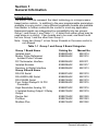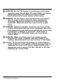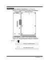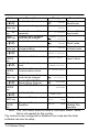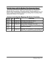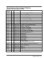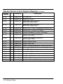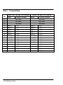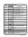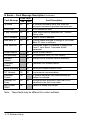
1
Modbus Plus Expansion Board Catalog No. EXB015A01 Installation and Operating Manual 8/03 MN1322 Table of Contents Section 1 General Information . . . . . . . . . . . . . . . . . . . . . . . . . . . . . Introduction . . . . . . . . . . . . . . . . . . . . . . . . . . . . . . . . . . . . . . . . . Limited Warranty . . . . . . . . . . . . . . . . . . . . . . . . . . . . . . . . . . . . . Safety Notice . . . . . . . . . . . . . . . . . . . . . . . . . . . . . . . . . . . . . . . . Section 2 Expansion Board Description . . . . . . . . . . . . . . . . . . . . Section 3 Installation . . . . . . . . . . . . . . . . . . . . . . . . . . . . . . . . . . . . . . Board Installation . . . . . . . . . . . . . . . . . . . . . . . . . . . . . . . . . . . . AC Controls . . . . . . . . . . . . . . . . . . . . . . . . . . . . . . . . . . . . . . . . . Single Expansion Board Installation . . . . . . . . . . . . . . . . . . Dual Expansion Board Installation . . . . . . . . . . . . . . . . . . . Section 4 Hardware Setup . . . . . . . . . . . . . . . . . . . . . . . . . . . . . . . . . DIP Switch Settings . . . . . . . . . . . . . . . . . . . . . . . . . . . . . . . . . . Cable Connection . . . . . . . . . . . . . . . . . . . . . . . . . . . . . . . . . . . . Powerup . . . . . . . . . . . . . . . . . . . . . . . . . . . . . . . . . . . . . . . . . . . . LED Indicators . . . . . . . . . . . . . . . . . . . . . . . . . . . . . . . . . . . . . . . Control Terminal Strip Connections . . . . . . . . . . . . . . . . . . . . . Section 5 Register Map for Modbus Plus . . . . . . . . . . . . . . . . . . . . 1-1 1-1 1-2 1-3 2-1 3-1 3-1 3-2 3-2 3-4 4-1 4-1 4-1 4-1 4-4 4-5 5-1 Table of Contents i ii Table of Contents Section 1 General Information Introduction The Baldor controls represent the latest technology in microprocessor based motor controls. In addition to the user programmable parameters available in every control, many different expansion boards are available from Baldor to further customize the control to most any application. Expansion boards are categorized by compatibility into two groups: Group 1 and Group 2, see Table 1-1. A board from either group may be used alone in a control. If two boards are to be used, one board must be from Group 1 and the other from Group 2. Note: Using two Group 1 or two Group 2 boards in the same control is not allowed. Table 1-1 Group 1 and Group 2 Board Categories Group 1 Board Name Isolated Input Master Pulse Reference/ Isolated Pulse Follower DC Tachometer Interface Isolated Encoder Resolver to Digital Interface Group 2 Board Name RS-232 Serial RS-422/RS-485 Serial RS-232/485 Serial Four Output Relays/3-15 PSI Pneumatic High Resolution Analog I/O 2 Isolated Analog Output/ 3 Relay Output Device Net Profibus Modbus Plus Catalog No. EXB003A0X EXB005A0X Manual No. MN1314 MN1312 EXB006A0X EXB008A0X EXB009A0X MN1311 MN1317 MN1313 EXB001A0X EXB002A0X EXB012A0X EXB004A0X MN1310 MN1310 MN1310 MN1315 EXB007A0X EXB010A0X MN1316 MN1319 EXB013A0X EXB014A0X EXB015A0X MN1320 MN1323 MN1322 General Information 1-1 Limited Warranty For a period of two (2) years from the date of original purchase, BALDOR will repair or replace without charge controls and accessories which our examination proves to be defective in material or workmanship. This warranty is valid if the unit has not been tampered with by unauthorized persons, misused, abused, or improperly installed and has been used in accordance with the instructions and/or ratings supplied. This warranty is in lieu of any other warranty or guarantee expressed or implied. BALDOR shall not be held responsible for any expense (including installation and removal), inconvenience, or consequential damage, including injury to any person or property caused by items of our manufacture or sale. (Some states do not allow exclusion or limitation of incidental or consequential damages, so the above exclusion may not apply.) In any event, BALDOR’s total liability, under all circumstances, shall not exceed the full purchase price of the control. Claims for purchase price refunds, repairs, or replacements must be referred to BALDOR with all pertinent data as to the defect, the date purchased, the task performed by the control, and the problem encountered. No liability is assumed for expendable items such as fuses. Goods may be returned only with written notification including a BALDOR Return Authorization Number and any return shipments must be prepaid. 1-2 General Information Safety Notice This equipment contains voltages that may be as great as 1000 volts! Electrical shock can cause serious or fatal injury. Only qualified personnel should attempt the start-up procedure or troubleshoot this equipment. This equipment may be connected to other machines that have rotating parts or parts that are driven by this equipment. Improper use can cause serious or fatal injury. Only qualified personnel should attempt the start-up procedure or troubleshoot this equipment. PRECAUTIONS WARNING: Do not touch any circuit board, power device or electrical connection before you first ensure that power has been disconnected and there is no high voltage present from this equipment or other equipment to which it is connected. Electrical shock can cause serious or fatal injury. Only qualified personnel should attempt the start-up procedure or troubleshoot this equipment. WARNING: Be sure that you are completely familiar with the safe operation of this equipment. This equipment may be connected to other machines that have rotating parts or parts that are controlled by this equipment. Improper use can cause serious or fatal injury. Only qualified personnel should attempt the start-up procedure or troubleshoot this equipment. General Information 1-3 WARNING: Be sure the system is properly grounded before applying power. Do not apply AC power before you ensure that all grounding instructions have been followed. Electrical shock can cause serious or fatal injury. WARNING: Do not remove cover for at least five (5) minutes after AC power is disconnected to allow capacitors to discharge. Dangerous voltages are present inside the equipment. Electrical shock can cause serious or fatal injury. WARNING: Improper operation of control may cause violent motion of the motor shaft and driven equipment. Be certain that unexpected motor shaft movement will not cause injury to personnel or damage to equipment. Peak torque of several times the rated motor torque can occur during control failure. WARNING: Motor circuit may have high voltage present whenever AC power is applied, even when motor is not rotating. Electrical shock can cause serious or fatal injury. Caution: To prevent equipment damage, be certain that the electrical service is not capable of delivering more than the maximum line short circuit current amperes listed in the appropriate control manual, 230 VAC, 460 VAC or 575 VAC maximum per control rating. 1-4 General Information Section 2 Expansion Board Description Introduction The Modbus Plus expansion board is a Group 2 expansion board. It allows a Series H control to communicate as a node on the Modbus Plus network. It has a DB9 connector to make connection to the network simple. Group 2 board Modbus Plus Expansion Board Catalog No. EXB015A01 A good resource document is the “Modicon Plus Network Planning and Installation Guide”. Refer to that guide for planning your network and details such as cable specifications etc. Description 2-1 2-2 Description Section 3 Installation Board Installation This section describes the Expansion Board installation procedure. Caution: Before you proceed, be sure to read and become familiar with the safety precautions at the beginning of this manual. Do not proceed if you are unsure of the safety precautions described. If you have any questions, contact BALDOR before you proceed. 1. 2. Remove the expansion board from the shipping container. Remove all packing material from the board. Caution: Be sure all packing materials are removed from the board. Conductive foam may be present on the connectors to prevent static build up during shipping. This can prevent proper circuit operation. If you are installing only one board, refer to the “Single Expansion Board Installation” procedure. If you are installing two expansion boards (or a second board) refer to the “Dual Expansion Board Installation” procedure. Installation 3-1 AC Controls (For all 15H Inverter, 21H Line Regen Inverter, 18H Vector, 22H Line Regen Vector and 23H Servo). Single Expansion Board Installation Procedure: 1. Be sure drive operation is terminated and secured. 2. Remove all power sources from the control. 3. Wait at least 5 minutes for internal capacitors to discharge. 4. Remove the four (4) Phillips head screws (1/4 turn) that secure the control cover. (For A & B size, remove four screws that secure the cover. On floor mounted G size enclosures, open the enclosure door). 5. Remove the control cover. 6. Slide the expansion board male connector into the female connector of the control board. See Figure 3-1. 7. Securely mount the expansion board to the sheet metal mounting plate using the #6 screws provided in the installation hardware. See Figure 3-2. 8. The mechanical installation of the expansion board is now complete. Refer to Section 4 of this manual and configure the jumpers as desired. Also complete the wiring before you proceed to step 9. 9. When complete, install the control cover using the four (4) Phillips head screws (1/4 turn). (For A & B size, install four screws that secure the cover. On floor mounted G size enclosures, close the enclosure door). 10. Restore all power sources to the control. 11. Restore drive operation. 3-2 Installation AC Controls Single Expansion Board Installation (Continued) Figure 3-1 Single Expansion Board Installation Expansion Board Motor Control Board Terminal tightening torque is 7 lb-in (0.8 Nm) maximum. Figure 3-2 Single Expansion Board Installation #6 Screw Group 1 or 2 Expansion Board Sheet Metal Mounting Plate Installation 3-3 AC Controls (Continued) Dual Expansion Board Installation Procedure: 1. Be sure drive operation is terminated and secured. 2. Remove all power sources from the control. 3. Wait at least 5 minutes for internal capacitors to discharge. 4. Remove the four (4) Phillips head screws (1/4 turn) that secure the control cover. (For A & B size, remove four screws that secure the cover. On floor mounted G size enclosures, open the enclosure door). 5. Remove the control cover. 6. Slide the Group 1 expansion board male connector into the female connector of the control board. See Figure 3-1. 7. Securely mount the Group 1 expansion board to the sheet metal mounting plate using the short standoffs provided in the installation hardware. See Figure 3-3. 8. The mechanical installation of the expansion board is now complete. Refer to the manual for the Group 1 board and configure the jumpers as desired. Also complete the wiring before you proceed to step 9. 9. Install the Group 2 board on top of the previously installed Group 1 board by plugging the female connector onto the male connector of the Group 1 board as shown in Figure 3-3. 10. Secure this Group 2 board to the Group 1 board using the #6 screws provided. See Figure 3-3. 11. The mechanical installation of the expansion board is now complete. Refer to the manual for the Group 2 board and configure any jumpers and switches as desired. Also complete the wiring for this board before you install or close the cover. 3-4 Installation AC Controls Dual Expansion Board Installation (Continued) 12. When complete, install the control cover using the four (4) Phillips head screws (1/4 turn). (For A & B size, install four screws that secure the cover. On floor mounted G size enclosures, close the enclosure door). 13. Restore all power sources to the control. 14. Restore drive operation. Figure 3-3 Dual Expansion Board Installation #6 Screw Group 2 Expansion Board Female Connector Short Aluminum Standoff Male Connector Group 1 Expansion Board Control Board Mounting Plate Installation 3-5 3-6 Installation Section 4 Hardware Setup A good resource document is the “Modicon Plus Network Planning and Installation Guide”. Refer to that guide for planning your network and details such as cable specifications etc. DIP Switch Settings This procedure will configure the Modbus Plus Expansion Board for communication with a computer or terminal. Reference Figure 4-1 and Table 4-1 for the following procedure. 1. Set DIP switches 1 through 6 for the desired board address. 2. Switches 7 and 8 are not used and may be left in either position. 3. Be sure a jumper is installed at J1. 4. Be sure no jumper is installed at J3 or J4. 5. Install the expansion board in the Series H control as instructed in Section 3 of this manual. Note: The switch settings can be changed after the board is powered up. However, switch changes will not take effect until the board is reset (by turning power off then on). Cable Connection Connect the Modbus cable to the DB 9 connector on the expansion board (shown in Figure 4-1). Powerup When the Modbus Plus expansion board is powered up it will do the following: 1. Perform a self test. 2. Check the switch settings for configuration information. 3. Verify communications with the Series H control board. 4. Check for power from the Series H control. 5. Perform a duplicate ID (address) check to determine if any other devices on the network have the same ID number. 6. Go online. Refer to the LED description in this section of the manual. Hardware Setup 4-1 Figure 4-1 Board Configuration Modbus Plus Expansion Board Catalog No. EXB015A01 D5 D5 Power LED J4 J1 PB1 Reset switch (Processor only) To reset the board, turn control off then on (cycle power). PB1 D2 Error LED D3 Status LED D4 Status LED S1 All switches shown in ON (Down) position. J3 1 2 3 4 5 6 7 8 D4 D3 D2 J2 D1 ON 1 2 3 4 5 6 7 8 Circuit Board DB9 Connector Pin Description 1 Chassis Ground 2 TxA 3 TxB D1 Modbus Plus Status LED 4-2 Hardware Setup Table 4-1 Switch Settings Modbus Plus Address 1 2 3 4 5 6 7 8 9 10 11 12 13 14 15 16 17 18 19 20 21 22 23 24 25 26 27 28 29 30 31 32 33 ... 63 1 0 1 0 1 0 1 0 1 0 1 0 1 0 1 0 1 0 1 0 1 0 1 0 1 0 1 0 1 0 1 0 1 0 ... 1 2 0 0 1 1 0 0 1 1 0 0 1 1 0 0 1 1 0 0 1 1 0 0 1 1 0 0 1 1 0 0 1 1 0 ... 1 S1 Switch Position 3 4 5 0 0 0 0 0 0 0 0 0 0 0 0 1 0 0 1 0 0 1 0 0 1 0 0 0 1 0 0 1 0 0 1 0 0 1 0 1 1 0 1 1 0 1 1 0 1 1 0 0 0 1 0 0 1 0 0 1 0 0 1 1 0 1 1 0 1 1 0 1 1 0 1 0 1 1 0 1 1 0 1 1 0 1 1 1 1 1 1 1 1 1 1 1 1 1 1 0 0 0 ... ... ... 1 1 1 6 0 0 0 0 0 0 0 0 0 0 0 0 0 0 0 0 0 0 0 0 0 0 0 0 0 0 0 0 0 0 0 0 1 ... 1 Hardware Setup 4-3 LED Indicators Five LED’s are located on the Modbus Plus expansion board (see Figure 4-1 for their locations). D1 Modbus Plus Status LED D1 displays the operational status of the Modbus Plus Interface expansion board (EXB). When power is first applied, the LED will pause, then flash slowly 8 times while it checks the network. If a valid Modbus Plus connection is established, D1 will flash continuously. Otherwise, it flash an error code as shown in Table 4-2. Table 4-2 LED State OFF 2 Flashes then pause 3 flashes then pause 4 flashes then pause Status Description No power is applied to the EXB. The network is active, but the token is never passed to this node. The node may have a bad transmitter. No other nodes on the network. Duplicate node numbers on the network. D2 Error LED D2 will flash 4 times then pause if any errors are encountered that would prevent correct operation of the board. If this error occurs, turn the control off, then on (cycle power). If error continues, the trouble could be the expansion board, motor control board, or software version. Correct the problem as required, and if the error remains, contact Baldor. D3 and D4 Status LED D3 will flash to indicate that firmware is correctly loaded and running. D4 will flash to indicate that the interface circuits between Modbus Plus expansion board and the Series H control is running correctly. These LEDs flash at different rates and, if flashing, indicate proper operation. D5 Power LED D5 indicates that the expansion board is receiving power from the Series H control. 4-4 Hardware Setup Control Terminal Strip Connections For Serial Mode operation, the Input/Output terminal strip of the control (J1 of the Vector and DC controls and J4 of the Inverters) is wired as shown in Figure 4-2. Connect the Enable, Forward Enable Switch, Reverse Enable Switch, External Trip and Opto Common connections as shown. Note: All opto-isolated outputs and analog outputs remain active while operating in the Serial Mode. When these connections are complete, refer to Section 5 of this manual and set the software for Serial Mode. Figure 4-2 Serial Opto Input Connections J1* Enable 8 Enable 8 Forward Enable Reverse Enable 9 Forward Enable Reverse Enable 9 10 External Trip 16 Common * ** J4** 17 10 16 External Trip Common 17 Series 18H, 22H and 23H controls. Series 15H and 21H controls. Hardware Setup 4-5 4-6 Hardware Setup Section 5 Register Map for Modbus Plus Configure Control Software for Modbus Plus Mode The Series H control operating mode must be set to Serial to use the Modbus Plus expansion board. There is no selection for Modbus Plus on the Level 1 Input block Operating mode parameter list. However, selecting Serial with the Modbus Plus expansion board installed will allow operation of the Modbus Plus board. Many commands in the Command Language can be used regardless of the setting of the control’s Operating Mode parameter (such as changing and viewing parameters). However, commands intended to control the motor shaft require the control be in the Serial (Modbus Plus) Mode. Note: The firmware version of the Series H control must support the Baldor Binary Protocol (BBP). To confirm that BBP is supported, perform the following: Scroll to the Level 2 Communications block, and view the selections. If RS485BBP is available, the software version is compatible with the Modbus Plus expansion board. Otherwise, contact Baldor to obtain a software update. During power up, the control checks if the communication board is installed. If an RS485 board is installed, the RS485BBP protocol is automatically selected during power up. Action Apply Power Press PROG key Press Y or B key Press Enter key Press Enter key Description Display illuminates If no fault is found and control is programmed for local mode,OR, If no fault is found and control is programmed for remote mode Access programming mode. Scroll to Level 1 Input block Display Comments Logo is displayed for 5 seconds. STP MOTOR SPEED Display mode. BALDOR MOTORS & DRIVES LOCAL 0RPM STP MOTOR SPEED REMOTE 0RPM Display mode. First screen in programming mode PRESS ENTER FOR Input Block. PRESS ENTER FOR PRESET SPEEDS INPUT First selection choice Flashing cursor indicates mode can be changed OPERATING MODE P: KEYPAD Now in keypad mode. OPERATING MODE KEYPAD Software Setup 5-1 Action Press Y or B key Press Enter key Press Y key Press Enter key Press Y or B key Press Enter key Press Y or B key Press ENTER key Press Y or B key Press ENTER key Press Enter key Press Y or B key Press ENTER key Press Y or B key Press DISP key Press LOCAL key Description Scroll to Serial mode Display OPERATING MODE SERIAL Saves mode change value OPERATING MODE P: SERIAL Scroll to Command Select parameter Flashing cursor indicates mode can be changed Scroll to Serial mode COMMAND SELECT P: +/–10VOLTS Saves change to serial command select Scroll to Level 2 blocks Comments Change to Serial mode. Now in ±10 Volt input mode. COMMAND SELECT +/–10VOLTS COMMAND SELECT SERIAL Change to Serial mode. COMMAND SELECT Control is now P: SERIAL in Serial mode. PRESS ENTER FOR LEVEL 2 BLOCKS Select Level 2 blocks. PRESS ENTER FOR OUTPUT LIMITS Scroll to Communications block Select Level 2 Communications block. PRESS ENTER FOR COMMUNICATIONS p: Flashing cursor indicates mode can be changed Scroll to RS 485 BBP (Baldor Binary Protocol) Select RS 485 BBP mode. First screen in Level 2 block PROTOCOL RS232 ASCII PROTOCOL RS232ASCII PROTOCOL RS485BBP p: PROTOCOL RS485BBP Scroll to Exit Menu PRESS ENTER FOR MENU EXIT Returns to Display mode. STP MOTOR SPEED LOCAL 0RPM Display mode. Changes to Serial Operation. STP MOTOR SPEED SERIAL 0RPM Ready for Modbus Plus operation. Note: The 15H control does not have a Command Select “Serial”, this is not needed for this control. The control is now configured for Modbus Plus mode and the Host software can now be setup. 5-2 Software Setup Data Exchange with the Modbus Plus Expansion Board This section describes the register interface used for data exchange with the Series H control. Motor drive parameters are mapped to Modbus Plus “Data/Holding” registers (4xxxx). Parameters can be read from or written to the Series H control by reading from or writing to the appropriate Modbus Plus registers. Common Area Register Mapping (All Series H Controls) Register Address T# Read/Write 40001 – Read/Write Watchdog polling flag (see Note 4) 41000 0 Write Only Null Transaction (see Note 3) 41001– 43999 61 Read/Write Baldor Control Parameters 1001–3999 (see Baldor Drive Installation & Operating Manual) 44000– 46999 49012 – 41 Read/Write Description Reserved for additions. Watchdog Time (0=disable) (10 ms minimum for vector) (1 sec. minimum for inverter) (see Note 3) Software Setup 5-3 For 15Hand 21H Inverter controls, use the following registers for communication. For all other H controls, use the Standard Series H Area Register Mapping. Series 15H Specific Area Register Mapping Register Address T# Read/Write 47000 31 Read Only Terminal Strip (see NOTE 1) 47001 45 Read Only Fault Status (0=no fault present) 47002 17 Read Only Current Actual (100mA RMS) 47003 18 Read Only Speed Actual (RPM) 47004 19 Read Only Frequency Actual (.1 Hz) 47005 33 Read Only Software Revision (ex S15–4.03 is returned as 403) 47006 34 Read Only Product Series (ex Series 15H returns 15) 47007 35 Read Only Product Class (5=H) 47008 1 Read/Write Run Cmd (0=stop, 1=fwd, 2=rev, 3=bipolar) 47009 5 Read/Write Command Mode (see NOTE 2) 47010 6 Read/Write Hz Speed Ref 47011 3 Read/Write Control Source (0=keypad, 1=terminal strip, 2=network) 47013 75 Write Only Digital Output 47014 46 Write Only Fault Reset (1=execute fault reset) 47012 Description Reserved Notes: After the fault is cleared (1=execute fault reset), you must send a stop (run cmd=0) followed by the direction for the run command again. Otherwise, the motor will not run. To use register 47008, you must jumper terminals J4–8, J4–9, J4–10 and J4–17 together to allow the motor to run. 5-4 Software Setup Standard Series H Area Register Mapping (except 15H and 21H controls) Register Address T# Read/Write Description 48000 17 Read Only Current Actual (100mA RMS) 48001 18 Read Only Speed Actual (RPM) 48002 19 Read Only Frequency Actual (.1 Hz) 48003 20 Read Only Power Actual (Watts) 48004 21 Read Only Input Voltage (Volts RMS) 48005 22 Read Only Output Voltage (Volts RMS) 48006 24 Read Only Motor Direction (0=fwd,1=rev) 48007 25 Read Only Zero Speed (1=at zero) 48008 26 Read Only At Speed (1=at commanded speed) 48009 27 Read Only Warning (1=warning) 48010 28 Read Only At Position (1=at position) 48011 29 Read Only At Setpoint (1=at setpoint) 48012 30 Read Only At Set Speed (1=at set speed) 48013 31 Read Only Terminal Strip (see NOTE 1) 48014 71 Read Only Analog Input 1 48015 72 Read Only Analog Input 2 48016 73 Write Only Analog Output 1 48017 74 Write Only Analog Output 2 48018 75 Write Only Digital Output 48019 33 Read Only Software Revision (ex S15–4.03 is returned as 403) 48020 34 Read Only Product Series (ex Series 15H returns 15) 48021 35 Read Only Product Class (5=H) 48022 36 Read Only Option Id 1 48023 37 Read Only Option Id 2 48024 38 Read Only Run Time (low order) 48025 38 Read Only Run Time (high order) Software Setup 5-5 Standard Series H Area Register Mapping Continued Register Address T# Read/Write 48100 6 Read/Write Hz Speed Ref 48101 7 Read/Write Speed Ref (RPM) 48102 8 Read/Write Speed Ref (High resolution – 1/256 RPM) (low order) 48103 8 Read/Write Speed Ref (High resolution – 1/256 RPM) (high order) 48104 9 Read/Write Torque Ref (±15 bits = programmed current limit) 48105 10 Read/Write Process Ref (±14 bits = full scale) 48106 11 Read/Write Process Feedback (±14 bits = full scale) 48107 12 Read/Write Position Ref (scaling=quadrature counts) (low order) 48108 12 Read/Write Position Ref (scaling=quadrature counts) (high order) 48109 13 Read/Write Position Speed (RPM) 48110 14 Read/Write Position Feed Fwd 48111 15 Read/Write Position (scaling=quadrature counts) (low order) 48112 15 Read/Write Position (scaling=quadrature counts) (high order) 48113 16 Read/Write Home Offset (low order) 48114 16 Read/Write Home Offset (high order) 48120 52 Write Only Calc Presets (1=execute preset calculation) 48121 53 Read/Write Auto Tune Mode (0=no test/cancel test) 48122 54 Read Only Auto Tune Data 48123 55 Read Only Auto Tune Status (0=failed, 1=pass, 2=running) 5-6 Software Setup Description Standard Series H Area Register Mapping Continued Register Address T# Read/Write 49000 1 Read/Write Run Cmd (0=stop, 1=fwd, 2=rev, 3=bipolar) 49001 2 Write Only Run Inhibit (1=stop, regardless of Control Source) 49002 3 Read/Write Control Source (0=keypad,1=terminal strip,2=network) 49003 5 Read/Write Command Mode (see NOTE 2) 49004 4 Read Only Control State (0=not ready, 1=ready, 2=enabled, 3=stopping, 4=faulted 49005 45 Read Only Fault Status (0=no fault present) 49006 46 Write Only Fault Reset (1=execute fault reset) 49007 49 Write Only Force Fault (0–1=force network fault) 49008 50 Read Only Security Status (0=disabled, 1=unlocked, 2=locked) 49009 51 Write Only Security Lock (valid code unlocks, any other locks) 49010 39 Read/Write Table Select (parameter table select 0–3) 49011 40 Read/Write Acc/Dec Group (1–2) 49012 41 Read/Write Watchdog Time (0=disable) (10 ms minimum for vector) (1 sec. minimum for inverter) (see NOTE 3) Description Note: To use register 49000, you must jumper terminals J1–8, J1–9, J1–10 and J1–17 together to allow the motor to run. Software Setup 5-7 Note 1: Terminal Strip Series 18H, 22H and 23H Controls Bit Name Terminal Number Series 15H and 21H Controls Name Terminal Number 15 Not Used Not Used 14 Not Used Not Used 13 Not Used Not Used 12 Input 1 J1–8 Input 1 J4–8 11 Input 2 J1–9 Input 2 J4–9 10 Input 3 J1–10 Input 3 J4–10 9 Input 4 J1–11 Input 4 J4–11 8 Input 5 J1–12 Input 5 J4–12 7 Input 6 J1–13 Input 6 J4–13 6 Input 7 J1–14 Input 7 J4–14 5 Input 8 J1–15 Input 8 J4–15 4 Input 9 J1–16 Input 9 J4–16 3 Output 1 J1–19 Output 1 J4–19 2 Output 2 J1–20 Output 2 J4–20 1 Output 3 J1–21 Output 3 J4–21 0 Output 4 J1–22 Output 4 J4–22 5-8 Software Setup Note 2: Command Mode Table Cmd Mode Class Description 0 None All 1 Torque CMD selected source S, V 2 Torque CMD network S, V Closes the current loop with command input from the Torque Ref. register. 3 Speed CMD selected source All Closes the velocity loop with command input from the source selected in the COMMAND SELECT parameter. 4 Speed CMD network All Closes the velocity loop with command input from the Speed Ref. register. 5 Orient S, V* C or Index channel orient. The motor will be commanded in the Fwd direction at the predefined homing speed until the index pulse is detected. The motor will then be commanded to hold position at the predefined home offset. 6 Position CMD ABS S,V* Closes the position loop with an absolute position command from the Position Ref. register. 7 Position CMD INC S, V* Closes the position loop with an incremental position command from the Position Ref. register. 8 9 No mode selected. Output stage of control remains off or disabled (voltage and current removed from the motor), regardless of Run Cmd condition. Closes the current loop with command input from the source selected in the COMMAND SELECT parameter. Reserved for future use. Position CMD external S, V* 11 Process Torque All Closes the torque process control loop. Commands come from the appropriate command input parameters. 12 Process Velocity All Closes the velocity process control loop. Commands come from the appropriate command input parameters. 13 Auto Tune E,S,V Changes command mode to Auto Tune. Test conditions are controlled by Auto Tune Mode. 10 Closes the position loop with command input from external option source (e.g. pulse follower exb). Reserved for future use. Software Setup 5-9 Class The class field indicates the product classes that support the transaction. The product codes are as follows: E = Encoderless Vector I = Inverter S = Servo V = Vector V* = Vector with custom software for positioning Note 3: Network Watchdog Timer The network watchdog timer is used by the drive to detect a communications loss. Normally, this functions as follows: On initialization/power up, the Watchdog Time = 0 (disabled). If any value other than 0 is written to the Watchdog Time, the timer activates. Thereafter, every time a network command is received, the internal timer is reset. When the time between network commands exceeds the value stored in this register, the control faults and disables the motor. The host must continuously send commands to keep the timer reset (a NULL command – a write to register 41000 – can be sent, if desired). Writing the watchdog time back to 0 disables the timer. Note 4: Watchdog Polling Flag If the Watchdog Polling Flag is set to 0, no automatic polling will take place. The Network Watchdog will function normally. If the Watchdog Polling Flag is set to 1, automatic polling will take place. This means that the Modbus Plus card will send NULL transactions to the Motor Drive every 20ms or so, as long as there is valid Modbus Plus communications (which means that there is at least one other Modbus Plus device on the network to pass the token to, and communications with that device are valid). This will keep the Network Watchdog timer from expiring unless the Modbus Plus network itself goes down. 5-10 Software Setup H Series – Fault Message Description Fault Code Fault Message Line Regen Fault Description 15H 18H 1 1 Fault in Line REGEN converter unit Series 21H Line REGEN Inverter control. 2 Loss of encoder feedback. Feedback Fault Invalid Base ID 3 3 Failed to read configuration from the Power Base ID value in software. Low INIT Bus V 4 4 Low bus voltage detected on start–up. Regen Res Power 5 5 Excessive power dissipation required by Dynamic Brake Hardware. Current SENS FLT 6 6 Failure to sense phase current. HW Desaturation 7 7 High output current condition detected (greater than 400% of rated output current). HW Ground Fault 8 8 Ground Fault detected (output current leakage to ground). Resolver Fault 9 Loss of resolver feedback. HW Power Supply 10 10 Control Board power supply failure detected. Overcurrent 11 11 Continuous current limit exceeded. Bus Overvoltage 12 12 High DC Bus voltage. Following ERR 13 Motor speed/position does not follow command. Torque Prove 14 Unbalanced current between all 3 phases. Bus Undervoltage 15 15 Low DC Bus voltage condition detected. 3 Sec Overload 16 16 Peak output current exceeded the 3 second rating value. Over Speed 17 Motor RPM exceeded 110% of MAX Speed. Motor Temp 18 Motor over temperature Heatsink Temp 19 19 Control heatsink exceeded temperature limit. External Trip 18 20 Connection at J1/J4 pin 16 and 17 is open. Param Checksum 51 21 Parameter checksum error. Software Setup 5-11 H Series – Fault Message Description Continued Fault Code Fault Message µp Reset 18H 22 22 A software watchdog timer has reset the processor because a process has timed out. 23 ROM checksum error. 24 Peak output current exceeded the 1 minute rating value. ROM Fault 1 Min Overload Fault Description 15H 24 No I Feedback 25 Loss of current feedback New Base ID 26 26 Control board detected a change in the Power Base ID value in software. EXB Selection 27 27 Expansion board not installed to support the Level 1 Input Block, Command Select parameter. Power module 28 Power module failure. Co–processor 29 Co–processor error (i.e. DSP board). Software Version 30 Wrong control software version detected. Feedback Module 31 Feedback HW module failure. Serial watchdog 32 Serial port transmit/receive error 33 Lost network communications. FLT Network 33 Hardware Protect 54 Unknown FLT Code 55 Bus Current SENS 56 Note A general hardware fault was detected but cannot be isolated. 34 Microprocessor detected a fault that is not identified in the fault code table. Failure to sense bus current. These faults may be different for custom software. 5-12 Software Setup BALDOR ELECTRIC COMPANY P.O. Box 2400 Fort Smith, AR 72902–2400 (479) 646–4711 Fax (479) 648–5792 Baldor Electric Company MN1322 Printed in USA 8/03 C&J500