1
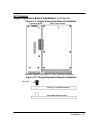
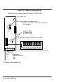
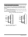
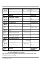
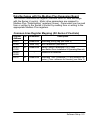
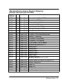
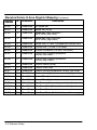
Section 4
Hardware Setup
A good resource document is the “Modicon Plus Network Planning and
Installation Guide”. Refer to that guide for planning your network and
details such as cable specifications etc.
DIP Switch Settings
This procedure will configure the Modbus Plus Expansion Board for
communication with a computer or terminal. Reference Figure 4-1 and
Table 4-1 for the following procedure.
1. Set DIP switches 1 through 6 for the desired board address.
2. Switches 7 and 8 are not used and may be left in either position.
3. Be sure a jumper is installed at J1.
4. Be sure no jumper is installed at J3 or J4.
5. Install the expansion board in the Series H control as instructed in
Section 3 of this manual.
Note: The switch settings can be changed after the board is powered
up. However, switch changes will not take effect until the board
is reset (by turning power off then on).
Cable Connection
Connect the Modbus cable to the DB 9 connector on the expansion
board (shown in Figure 4-1).
Powerup
When the Modbus Plus expansion board is powered up it will do the
following:
1. Perform a self test.
2. Check the switch settings for configuration information.
3. Verify communications with the Series H control board.
4. Check for power from the Series H control.
5. Perform a duplicate ID (address) check to determine if any other
devices on the network have the same ID number.
6. Go online.
Refer to the LED description in this section of the manual.
Hardware Setup 4-1