1
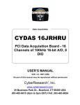
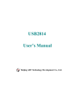
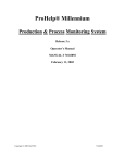
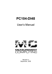
CyDAS Series
CyDAS 8AOH
CyDAS 8AOL
CyDAS 8AOM
Data Acquisition Boards
CyDAS 8AOH: CyDAS 8PGH plus two 12-bit D/A channels
CyDAS 8AOL: CyDAS 8PGL plus two 12-bit D/A channels
CyDAs 8AOM: CyDAS 8PGM plus two 12-bit D/A channels
(DAS-8 Compatible)
USER’S MANUAL
VER. 5
• OCT 2000
&
No part of this manual may be reproduced without permission.
CyberResearch®, Inc.
www.cyberresearch.com
25 Business Park Dr., Branford, CT 06405 USA
203-483-8815 (9am to 5pm EST) FAX: 203-483-9024
©Copyright 2000
All Rights Reserved.
October 2000
The information in this document is subject to change without prior notice in order
to improve reliability, design, and function and does not represent a commitment
on the part of CyberResearch, Inc.
In no event will CyberResearch, Inc. be liable for direct, indirect, special,
incidental, or consequential damages arising out of the use of or inability to use
the product or documentation, even if advised of the possibility of such damages.
This document contains proprietary information protected by copyright. All rights
are reserved. No part of this manual may be reproduced by any mechanical,
electronic, or other means in any form without prior written permission of
CyberResearch, Inc.
TRADEMARKS
“CyberResearch,” “CyDAS 8AOH,” “CyDAS 8AOL,” and “CyDAS 8AOM” are
trademarks of CyberResearch, Inc. Other product names mentioned herein are
used for identification purposes only and may be trademarks and/or registered
trademarks of their respective companies.
• NOTICE •
CyberResearch, Inc. does not authorize any CyberResearch product for use in life
support systems, medical equipment, and/or medical devices without the written
approval of the President of CyberResearch, Inc. Life support devices and
systems are devices or systems which are intended for surgical implantation into
the body, or to support or sustain life and whose failure to perform can be
reasonably expected to result in injury. Other medical equipment includes devices
used for monitoring, data acquisition, modification, or notification purposes in
relation to life support, life sustaining, or vital statistic recording. CyberResearch
products are not designed with the components required, are not subject to
the testing required, and are not submitted to the certification required to ensure
a level of reliability appropriate for the treatment and diagnosis of humans.
i
ii
TABLE OF CONTENTS
1 INTRODUCTION . . . . . . . . . . . . . . . . . . . . . . . . . . . . . . . . . . . . . . . . . . . . . . . . . . . . . . . . 1
2 SOFTWARE INSTALLATION . . . . . . . . . . . . . . . . . . . . . . . . . . . . . . . . . . . . . . . . . . . . . . 3
3 HARDWARE INSTALLATION . . . . . . . . . . . . . . . . . . . . . . . . . . . . . . . . . . . . . . . . . . . . . 5
3.1 BASE ADDRESS . . . . . . . . . . . . . . . . . . . . . . . . . . . . . . . . . . . . . . . . . . . . . . . . . . 5
3.2 INTERRUPT LEVEL SELECT . . . . . . . . . . . . . . . . . . . . . . . . . . . . . . . . . . . . . . . . 6
3.3 XTAL/PC BUS CLOCK JUMPER . . . . . . . . . . . . . . . . . . . . . . . . . . . . . . . . . . . . . 6
3.4 WAIT STATE . . . . . . . . . . . . . . . . . . . . . . . . . . . . . . . . . . . . . . . . . . . . . . . . . . . . . 7
3.5 D/A RANGE SWITCH . . . . . . . . . . . . . . . . . . . . . . . . . . . . . . . . . . . . . . . . . . . . . . 7
3.6 D/A SIMULTANEOUS UPDATE JUMPER . . . . . . . . . . . . . . . . . . . . . . . . . . . . . 8
3.7 INSTALL THE CYDAS 08AOx IN THE COMPUTER . . . . . . . . . . . . . . . . . . . . . 8
4 CALIBRATION AND TEST . . . . . . . . . . . . . . . . . . . . . . . . . . . . . . . . . . . . . . . . . . . . . . . 9
5 SIGNAL CONNECTION . . . . . . . . . . . . . . . . . . . . . . . . . . . . . . . . . . . . . . . . . . . . . . . . . . 11
5.1 ANALOG CONNECTOR DIAGRAM . . . . . . . . . . . . . . . . . . . . . . . . . . . . . . . . . . 11
5.2 DIFFERENTIAL INPUTS . . . . . . . . . . . . . . . . . . . . . . . . . . . . . . . . . . . . . . . . . . . . 11
5.3 DIGITAL OUTPUTS & INPUTS OP0-2 & IP0-3 . . . . . . . . . . . . . . . . . . . . . . . . . . 12
5.4 DIGITAL I/O CONNECTOR . . . . . . . . . . . . . . . . . . . . . . . . . . . . . . . . . . . . . . . . .12
6 CYDAS 8AOX ARCHITECTURE . . . . . . . . . . . . . . . . . . . . . . . . . . . . . . . . . . . . . . . . . . 13
6.1 REGISTER LAYOUT . . . . . . . . . . . . . . . . . . . . . . . . . . . . . . . . . . . . . . . . . . . . . . .13
6.2 A/D DATA REGISTER . . . . . . . . . . . . . . . . . . . . . . . . . . . . . . . . . . . . . . . . . . . . . 14
6.3 STATUS AND CONTROL REGISTER . . . . . . . . . . . . . . . . . . . . . . . . . . . . . . . . 15
6.4 PROGRAMMABLE GAIN REGISTER . . . . . . . . . . . . . . . . . . . . . . . . . . . . . . . . 15
6.5 COUNTER LOAD & READ REGISTERS . . . . . . . . . . . . . . . . . . . . . . . . . . . . . . 17
6.6 COUNTER CONTROL REGISTER . . . . . . . . . . . . . . . . . . . . . . . . . . . . . . . . . . . 18
6.7 COUNTER TIMER OPERATION . . . . . . . . . . . . . . . . . . . . . . . . . . . . . . . . . . . . 18
6.8 D/A 0 CONTROL REGISTERS . . . . . . . . . . . . . . . . . . . . . . . . . . . . . . . . . . . . . . 19
6.9 D/A 1 CONTROL REGISTERS . . . . . . . . . . . . . . . . . . . . . . . . . . . . . . . . . . . . . . 20
6.10 82C55 CONTROL & DATA REGISTERS . . . . . . . . . . . . . . . . . . . . . . . . . . . . 21
7 SPECIFICATIONS . . . . . . . . . . . . . . . . . . . . . . . . . . . . . . . . . . . . . . . . . . . . . . . . . . . . . . 23
8 APPLICATION NOTES . . . . . . . . . . . . . . . . . . . . . . . . . . . . . . . . . . . . . . . . . . . . . . . . . . 27
8.1 VOLTAGE DIVIDERS . . . . . . . . . . . . . . . . . . . . . . . . . . . . . . . . . . . . . . . . . . . . . 27
8.2 DIFFERENTIAL & SINGLE ENDED INPUTS . . . . . . . . . . . . . . . . . . . . . . . . . . 28
8.3 COMMON MODE RANGE . . . . . . . . . . . . . . . . . . . . . . . . . . . . . . . . . . . . . . . . . 28
8.4 COMMON MISUNDERSTANDINGS . . . . . . . . . . . . . . . . . . . . . . . . . . . . . . . . . 29
8.5 GROUND LOOPS . . . . . . . . . . . . . . . . . . . . . . . . . . . . . . . . . . . . . . . . . . . . . . . . . 29
8.6 USE OF SINGLE-ENDED INPUTS . . . . . . . . . . . . . . . . . . . . . . . . . . . . . . . . . . . 29
8.7 LOW PASS FILTERS . . . . . . . . . . . . . . . . . . . . . . . . . . . . . . . . . . . . . . . . . . . . . . 30
This page deliberately left blank.
iv
1 INTRODUCTION
The CyDAS 8AO family of boards, referred to as CyDAS 8AOx in this manual, has three members. Where specific
aspects of a board are described, the specific part number CyDAS 8AOH, CyDAS 8AOL, or CyDAS 8AOM are used.
The three boards differ only in the A/D gain ranges. The AOH has 'high' gains, the AOL has 'low' gains, and the AOM has
'MetraByte' gains and gain codes.
The analog amplifier is located approximately in the center of the board. The amplifier on the CyDAS 8AOH and
CyDAS 8AOM is part number PGA202. The amplifier on the CyDAS 8AOL is part number PGA203.
The CyDAS 8AOx boards are an extension of the popular CyDAS 8 architecture. The two boards are identical at the
register level, performance and connector with the following exceptions.
1.
Gains are software-programmable. There is only one version of the MetraByte™ DAS-8AO with gains of 0.5, 1, 10, 100,
and 500. CyberResearch offers two versions. They are the CyDAS 8AOH and CyDAS 8AOL. The 'H' gains are
0.5, 1, 5, 10, 50, 100, 500, and 1000. The 'L' gains are 0.5, 1, 2, 4, and 8.
2.
Analog inputs are differential vs. the single-ended inputs of a CyDAS 8. To maintain compatibility with signal
conditioning boards such as the CyEXP 16, an optional SIP resistor provides ground reference to the CH LO inputs.
3.
A stable crystal oscillator provides the A/D pacer clock pulse. To allow software-compatibility with programs written for
the CyDAS 8, a jumper is provided to choose between the crystal or the PC Bus clock.
4.
A DC/DC converter supplies stable +/-15V power to the analog circuitry. An optional version of the board without the
DC/DC converter is available on special order of 10 or more units. The cost is lower but the ranges of analog inputs are
limited.
5.
There is a second digital connector on the CyDAS 8AOx as there is on the CyDAS 8. The MetraByte DAS-08AO
does not provide the additional digital I/O lines.
1
This page deliberately left blank.
2
2 SOFTWARE INSTALLATION
Before you open your computer and install the board, install and run InstaCal™, the installation, calibration and test utility
included with your board. InstaCal™ will guide you through switch and jumper settings for your board. Detailed information
regarding these settings can be found below. Refer to the Software Installation manual for InstaCal™ installation instructions.
3
This page deliberately left blank.
4
3 HARDWARE INSTALLATION
The CyDAS 8AOx has three banks of switches and three jumper blocks which must be set before installing the board
in your computer.
3.1 BASE ADDRESS
The base address of the CyDAS 8AOx is set by switching a bank
of DIP switches on the board (Figure 3-1). This bank of switches is
labeled ADDRESS and numbered 9 to 4.
Ignore the word ON and the numbers printed on the switch
The switch works by adding up the weights of individual switches to
make a base address. A 'weight' is active when the switch is down.
Shown to the right, switches 9 and 8 are down, all others are up.
Weights 200h and 100h are active, equaling 300h base address. Refer
to Table 1-1 for a list of standard PC addresses.
Figure 3-1. Base Address Switches
ADDRESS
RANGE
000-00F
020-021
040-043
060-063
060-064
070-071
080-08F
0A0-0A1
0A0-0AF
0C0-0DF
0F0-0FF
1F0-1FF
200-20F
210-21F
238-23B
23C-23F
270-27F
2B0-2BF
Table 3-1. Standard PC I/O Addresses
FUNCTION
ADDRESS
FUNCTION
RANGE
8237 DMA #1
2C0-2CF
EGA
8259 PIC #1
2D0-2DF
EGA
8253 TIMER
2E0-2E7
GPIB (AT)
8255 PPI (XT)
2E8-2EF
SERIAL PORT
8742 CONTROLLER (AT)
2F8-2FF
SERIAL PORT
CMOS RAM & NMI
300-30F
PROTOTYPE CARD
MASK (AT)
DMA PAGE REGISTERS
310-31F
PROTOTTYPE CARD
8259 PIC #2 (AT)
320-32F
HARD DISK (XT)
NMI MASK (XT)
378-37F
PARALLEL PRINTER
8237 #2 (AT)
380-38F
SDLC
80287 NUMERIC CO-P
3A0-3AF
SDLC
(AT)
HARD DISK (AT)
3B0-3BB
MDA
GAME CONTROL
3BC-3BF
PARALLEL PRINTER
EXPANSION UNIT (XT)
3C0-3CF
EGA
BUS MOUSE
3D0-3DF
CGA
ALT BUS MOUSE
3E8-3EF
SERIAL PORT
PARALLEL PRINTER
3F0-3F7
FLOPPY DISK
EGA
3F8-3FF
SERIAL PORT
5
3.2 INTERRUPT LEVEL SELECT
The interrupt jumper need only be set if the software you are using
requires it. If you do set the interrupt jumper, please check your PC's
current configuration for interrupt conflicts, and do not use IR2 in
PC/AT class machines (or higher).
There is a jumper block on the CyDAS 8AOx located just above the
PC bus interface (gold pins). The factory default setting is that no
interrupt level is set. The jumper is in the 'X' position.
Figure 3-2. Interrupt Jumper Block
If you need to pace conversions through hardware (either the on - board pacer or an external clock), move this jumper to one
of the other positions (see table 3-2).
The following table shows some typical interrupt assignments on a PC. The CyDAS 8AOx may be configured for
interrupt levels 2 through 7. The levels most often available are 5 and 7.
NAME
NMI
IRQ0
IRQ1
IRQ2
IRQ3
IRQ4
IRQ5
IRQ6
IRQ7
Table 3-2. Interrupt Assignments
DESCRIPTION
NAME
DESCRIPTION
PARITY
IRQ8
REAL TIME CLOCK (AT)
TIMER
IRQ9
RE-DIRECTED TO IRQ2
(AT)
KEYBOARD
IRQ10
UNASSIGNED
RESERVED (XT)
IRQ11
UNASSIGNED
INT 8-15 (AT)
COM OR SDLC
IRQ12
UNASSIGNED
COM OR SDLC
IRQ13
80287 NUMERIC CO-P
HARD DISK (XT)
IRQ14
HARD DISK
LPT (AT)
FLOPPY DISK
IRQ15
UNASSIGNED
LPT
Note: IRQ8-15 are AT only
3.3 XTAL/PC BUS CLOCK JUMPER
The A/D pacer clock sources for the MetraByte DAS-8PGA and DAS-8 are different. The source for the DAS-8PGA is fixed
at 1 MHz while the source for the DAS-8 is dependent on PC bus speed. The CyDAS 8AOx attempts to deal with these
differences in a way that satisfies software written for either board.
The CyDAS 8AOx is equipped with a jumper which allows you to
choose the source of the A/D pacer clock pulse (Figure 3-3). The default
for this jumper is the 1 MHz position.
The MetraByte DAS-8PGA is only available with a 1MHz XTAL as the
source for the A/D pacer clock. This created problems for users who
wanted to use the DAS-8PGA in place of the DAS-8and use existing
software because the DAS-8 gets its A/D pacer clock pulse from the PC
Bus Clock.
Figure 3-3. Clock Source Jumper
If you need compatibility with the DAS-8 pacing scheme, you can select the PC Bus Clock as the source for the A/D pacer
clock.
6
3.4 WAIT STATE
O
N
O
F
F
A wait state may be enabled on the CyDAS 8AOx by selecting WAIT
STATE ON at the jumper provided on the board. Enabling the wait state
causes the personal computer's bus transfer rate to slow down whenever the
CyDAS 8AOx is written to or read from.
The wait state jumper is provided in case you one day own a personal
computer with an I/O bus transfer rate which is too fast for the
CyDAS 8AOx. If your board were to fail sporadically in random ways,
you could try using it with the wait state ON.
WAIT
STATE
WAIT STATE JUMPER BLOCK - A
wait state is not selected on this
jumper block. For a wait state,
place the jumper on the two
leftmost pins.
Figure 3-4. Wait State Jumper Block
3.5 D/A RANGE SWITCH
The analog output voltage range is selectable. A set of DIP switches, one set of six per channel, allow you to choose
a range for each channel (Figure 3-5 and Table 3-3). .
Figure 3-5. Analog Output Range Switches - Typical
RANGE
+/-10V
+/-5V
+/-2.5V
+/-1.67V
0-10V
0-5V
0-2.5V
0-1.67
Table 3-3. Analog Output Range Select Switches Coding
S1
S2
S3
S4
S5
U
D
U
D
D
U
D
D
U
D
U
D
D
D
U
U
D
D
D
D
D
U
U
D
D
D
U
D
U
D
D
U
D
D
U
D
U
D
D
D
RANGE SELECTION SWITCH SETTINGS - U = Up, D = Down
7
S6
D
D
D
U
D
D
D
U
3.6 D/A SIMULTANEOUS UPDATE JUMPER
The dual D/A converter can be updated simultaneously or individually. A jumper controls this feature.
When the jumper (see Figure 3-6) is in the NORMAL position, the DAC low byte is written to first, then the high byte
(4-bit nibble). When the high byte is written, the DAC output is updated.
When the jumper is in the SIM position, both DACs outputs are updated when you read from DAC 0 Low Byte. First you
must load the new output value into both or one DAC, then when the DACs have the correct output value loaded, read from
BASE + 8 and the outputs will be updated. Analog Output Range Select Switches
D/A Simultaneous
Update Jumper
Figure 3-6. CyDAS 8AOx Board Layout
3.7 INSTALL THE CyDAS 8AOx IN THE COMPUTER
Turn the power off.
Remove the cover of your computer. Please be careful not to dislodge any of the cables installed on the boards in your
computer as you slide the cover off.
Locate an empty expansion slot in your computer.
Push the board firmly down into the expansion bus connector. If it is not seated fully it may fail to work and could short
circuit the PC bus power onto a PC bus signal. This could damage the motherboard in your PC as well as the
CyDAS 8AOx.
8
4 CALIBRATION AND TEST
The CyDAS 8AOx is supplied with InstaCal software which also performs calibration and board testing. Every board is
fully tested and calibrated before shipment. For normal environments, a calibration interval of 6 months to one year is
recommended. If frequent variations in temperature or humidity are common, re-calibrate at least every three months.
It requires less than 30 minutes to calibrate the CyDAS 8AOx.
The CyDAS 8AOx does not require recalibration when moved from one computer to another. The reason is that the board has
a stable DC/DC converter on-board which supplies the analog +/−15V voltages.
9
This page deliberately left blank.
10
5 SIGNAL CONNECTION
Making correct signal connections is one of the most important aspects of applying a data acquisition board. Failure to properly
connect signals is the most common reason for calls to technical support. Usually, a problem can be located by cross-checking the
wiring against the connector diagram
5.1 ANALOG CONNECTOR DIAGRAM
The CyDAS 8AOx analog connector is a male 37-pin D-type connector,
accessible from the rear of the PC through the expansion backplate.
The connector accepts female 37-pin D-type connectors, such as those on
the CBL 7302, 2 foot cable with connectors.
If frequent changes to signal connections or signal conditioning is required,
please refer to the information on the STA 01 and CySTP 37 screw
terminal boards, CyEX P32, 32-channel analog MUX/AMP.
Isolation amplifiers may be mounted using the CySTA 5B08 and
5B isolation modules.
CH 0 LOW
CH 1 LOW
CH 2 LOW
CH 3 LOW
CH 4 LOW
CH 5 LOW
CH 6 LOW
CH 7 LOW
L.L. GND
OP4
OP3
OP2
OP1
OUT 2
OUT 1
CLK 1
OUT 0
CLK 0
DAC I OUT
19
18
17
16
15
14
13
12
11
10
9
8
7
6
5
4
3
2
1
37
36
35
34
33
32
31
30
29
28
27
26
25
24
23
22
21
20
CH 0 HIGH
CH 1 HIGH
CH 2 HIGH
CH 3 HIGH
CH 4 HIGH
CH 5 HIGH
CH 6 HIGH
CH 7 HIGH
PC BUS +5
DIGITAL GND
IP3
IP2
IP1
IR INPUT
GATE 2
GATE 1
D/A LLGND
DAC 0 OUT
37 PIN CONNECTOR
Figure 4-1. Analog Connector Diagram
5.2 DIFFERENTIAL INPUTS
The CyDAS 8AOx has eight differential analog inputs. For a detailed description of differential vs. single-ended analog
inputs, turn to the section of this manual on Analog Electronics.
Briefly, differential inputs are three-wire analog hookups consisting of a signal-high, a signal-low, and a chassis ground. The
benefits of differential inputs are the ability to reject noise, and the ability to eliminate ground loops or potentials between
signal low and chassis ground.
Although differential inputs are often preferable to single ended inputs, there are occasions when the floating nature of a
differential input can cause input reading difficulties. In those cases, the CyDAS 8AOx inputs can be converted to
modified differential.
Examine the diagram of the CyDAS 8AOx board. A position for an optional Single Inline Package (SIP) of resistors is
located near the 37-pin connector. Installing the SIP converts the analog inputs from fully differential to modified differential
with a resistive reference to ground. A SIP resistor network is included with the board for this purpose.
11
NOTE: When using the CyDAS 8PGx with the CyEXP 16 or CyEXP 32, the optional SIP resistor must be
installed. The CyEXP 16 and CyEXP 32 (and MetraByte EXP16) were designed to interface to a single-ended
input. Failure to install the SIP resistor when the board is used with these expansion boards will result in floating,
unstable readings.
Special instructions and solder are packaged with the SIP resistor. Follow the installation instructions
carefully and use the solder provided. Use of any other solder, or failure to follow instructions can result in
a degradation of the analog input's accuracy and may require out-of-warranty repair.
5.3 DIGITAL OUTPUTS & INPUTS OP0-2 & IP0-3
The digital outputs and inputs located on the main, or analog connector, may best be reserved for use as CyEXP mux
controls or trigger inputs. General digital interfacing should be done on the rear 24-bit digital connector.
The digital inputs/outputs on the CyDAS 8AOx are at TTL level. TTL is an electronics industry term, short for Transistor
Transistor Logic, with describes a standard for digital signals. It is a common misconception that TTL signals are always 0V
for low and +5V for high. Although the low signal is reliably close to 0V, the high signal may be anywhere from 2.4V to 5V,
and be within the TTL specification.
5.4 DIGITAL I/O CONNECTOR
The 24 bits of digital I/O at the rear of the board are brought to a 40-pin header connector. You can assemble your own cable
or purchase a CBL 3740 which translates the 40-pin header into a 37-pin, D-type connector with mounting bracket.
Figure 4-2 is the schematic for the CBL 3740.
After connection to a CBL 3740, the signals at the 37-pin D connector are exactly the same as a CyDIO 24 or MetraByte
PIO12 standard.
Figure 4-3 has the pin assignments at the 37-pin connector.
Figure 4-2. CBL 3740 Cable Schematic
Figure 4-3. Pin Assignments on D-37 End of CBL 3740
12
6 CYDAS 8AOx ARCHITECTURE
All of the programmable functions of the CyDAS 8AOx are accessible through the control and data registers, which are
explained here.
6.1 REGISTER LAYOUT
The CyDAS 8AOx is controlled and monitored by writing to and reading from 16 consecutive 8-bit I/O addresses.
The first address, or BASE ADDRESS, is determined by setting a bank of switches on the board.
Register manipulation is best left to experienced programmers as most of the possible functions are implemented in
easy to use Universal Library™.
The register descriptions use the following format:
7
A/D9
6
A/D10
5
A/D11
4
A/D12
LSB
3
CH8
2
CH4
1
CH2
0
CH1
The numbers along the top row are the bit positions within the 8-bit byte and the numbers and symbols in the bottom row are
the functions associated with that bit.
To write to or read from a register in decimal or hexadecimal, the bit weights in Table 6-1 apply:
BIT POSITION
0
1
2
3
4
5
6
7
Table 6-1. Byte Bit Weights
DECIMAL VALUE
1
2
4
8
16
32
64
128
HEX VALUE
1
2
4
8
10
20
40
80
To write control words or data to a register, the individual bits must be set to 0 or 1 then combined to form a byte. Data read
from registers must be analyzed to determine which bits are on or off.
The method of programming required to set/read bits from bytes is beyond the scope of this manual. It will be covered in
most Introduction To Programming books, available from a bookstore.
In summary form, the registers and their function are listed on Table 6-2. Within each register are eight bits which may
constitute a byte of data or they may be eight individual bit set/read functions.
13
ADDRESS
BASE
BASE + 1
BASE + 2
BASE + 3
BASE + 4
BASE + 5
BASE + 6
BASE + 7
BASE + 8
BASE + 9
BASE + 10
BASE + 11
BASE + 12
BASE + 13
BASE + 14
BASE + 15
Table 6-2. Register Functions
READ FUNCTION
WRITE FUNCTION
A/D Bits 9 - 12 (LSB)
Start 8 bit A/D conversion
A/D Bits 1 (MSB) - 8
Start 12 bit A/D conversion
EOC, IP1 - IP3, IRQ, MUX Address
OP1 - OP4, INTE & MUX Address
Channel MUX and Gain Status
Programmable gain control
Read Counter 0
Load Counter 0
Read Counter 1
Load Counter 1
Read Counter 2
Load Counter 2
Not used
Counter Control
Simultaneous Update
DAC 0 Low Byte
Simultaneous Update
DAC 0 High Byte (& individual update)
Simultaneous Update
DAC 1 Low Byte
Simultaneous Update
DAC 1 High Byte (& individual update)
PORT A 82C55
PORT A 82C55
PORT B 82C55
PORT B 82C55
PORT C 82C55
PORT C 82C55
None
82C55 Control
6.2 A/D DATA REGISTER
BASE ADDRESS (Read / Write)
7
6
A/D9
A/D10
5
A/D11
4
A/D12
LSB
3
0
2
0
1
0
0
0
READ
On read, it contains the least significant four digits of the analog input data.
These four bits of analog input data must be combined with the eight bits of analog input data in BASE + 1, forming a
complete 12 bit number. The data is in the format 0 = minus full scale. 4095 = +FS.
WRITE
Writing any data to the register causes an immediate 8-bit A/D conversion.
BASE ADDRESS + 1 (Read / Write)
7
6
5
A/D1
A/D2
A/D3
MSB
4
A/D4
3
A/D5
2
A/D6
1
A/D7
0
A/D8
READ
On read the most significant A/D byte is read.
The A/D Bits code corresponds to the voltage on the input according to the table below.
DECIMAL
4095
2048
0
HEX
FFF
800
0
BIPOLAR
+ Full Scale
0 Volts
- Full Scale
UNIPOLAR
+ Full Scale
½ Full Scale
0 Volts
WRITE
Writing to this register starts a 12-bit A/D conversion.
A note of caution: Place several NO-OP instructions between consecutive 12-bit A/D conversions to avoid overrunning the
A/D converter.
14
6.3 STATUS AND CONTROL REGISTER
BASE ADDRESS + 2 (Read / Write) Read Functions
7
6
5
4
EOC
IP3
IP2
IP1
3
IRQ
2
MUX2
1
MUX1
0
MUX0
READ = STATUS
EOC = 1 the A/D is busy converting and data should not be read.
EOC = 0 the A/D is not busy and data may be read.
IP3 to IP1 are the digital input lines on the 37-pin analog connector.
IRQ is the status of an edge triggered latch connected to pin 24 of the analog connector. It is high (1) when a positive edge
has been detected. It may be reset to 0 by writing to the INTE mask at BASE + 2 write.
MUX 2 to MUX 0 is the current multiplexer channel. The current channel is a binary coded number between 0 and 7 .
WRITE = CONTROL
BASE + 2 (Read / Write) Write Functions
7
6
5
OP4
OP3
OP2
4
OP1
3
INTE
2
MUX2
1
MUX1
0
MUX0
OP4 to OP1 are the digital output lines on the 37-pin analog connector.
INTE = 1 enables interrupts (positive edge triggered) onto the PC bus IRQ selected via the IRQ jumper on the
CyDAS 8AOx.
INTE = 0 disables the passing of the interrupt detected at pin 24 to the PC bus.
IRQ is set to 1 every time an interrupt occurs. If you want to process successive interrupts then set INTE = 1 as the last step
in your interrupt service routine.
MUX2 to MUX0. Set the current channel address by writing a binary coded number between 0 and 7 to these three bits.
NOTE
Every write to this register sets the current A/D channel MUX setting to the number in bits 2-0.
6.4 PROGRAMMABLE GAIN REGISTER
BASE ADDRESS + 3
A software-programmable register controls the input amplifier. It allows you to select unipolar/bipolar ranges and gains of 1,
10, 100 or 1000 (...AOH) or 1, 2, 4 or 8 (...AOL) via software command.
The register is addressed at the board's Base Address + 3. This register is unused on the CyDAS 8 and so represents no
conflict with existing CyDAS 8 software.
To set the input range of the CyDAS 8AOx board, select the desired range from the table and write the code in decimal or
hexadecimal to base address +3. Here is an example in BASIC:
100 OUT &H303, 6
'Set gain = 1000, +/-0.005V range.
15
The register's Write layout is :
BASE + 3 (Read / Write) Write Functions
BIT 7
BIT 6
BIT 5
X
X
X
BIT 4
X
BIT 3
R3
BIT 2
R2
BIT 1
R1
BIT 0
R0
The register's Read layout is :
BASE + 3 (Read / Write) Read Functions
BIT 7
BIT 6
BIT 5
X
MA2
MA1
BIT 4
MA0
BIT 3
R3
BIT 2
R2
BIT 1
R1
BIT 0
R0
R3 to R0: Indicate the current analog input range.
MA2 to MA0: Indicate the analog input channel that is currently selected (by writing to base +2).
6.4.1 CYDAS 8AOH GAIN/RANGES
The gain/range of the board is controlled by writing a control code to the Base + 3 register. The gain/range codes are:
BI-POLAR AOH
GAIN
RANGE V
0.5
+/-10
1
+/-5
5
+/-1
10
+/-0.5
50
+/-0.1
100
+/-0.05
500
+/-0.01
1000
+/-0.005
DEC
8
0
10
2
12
4
14
6
CONTROL CODES
HEX
R3
R2
8
1
0
0
0
0
A
1
0
2
0
0
C
1
1
4
0
1
E
1
1
6
0
1
R1
0
0
1
1
0
0
1
1
R0
0
0
0
0
0
0
0
0
UNI-POLAR AOH
GAIN
RANGE V
1
0 to 10
10
0 to 1
100
0 to 0.1
1000
0 to 0.01
DEC
1
3
5
7
CONTROL CODES
HEX
R3
R2
1
0
0
3
0
0
5
0
1
7
0
1
R1
0
1
0
1
R0
1
1
1
1
6.4.2 CYDAS 8AOL GAIN/RANGES
There are fewer ranges available for the CyDAS 8AOL. Gains of 2, 4 & 8 are often called binary gains. These
ranges are not available on the MetraByte DAS-8AO. The gain/range of the board is controlled by writing a control code
to the Base + 3 register.
BI-POLAR AOL
GAIN
RANGE V
0.5
+/-10
1
+/-5
2
+/-2.5
4
+/-1.25
8
+/-0.625
DEC
8
0
2
4
6
16
CONTROL CODES
HEX
R3
R2
R1
8
1
0
0
0
0
0
0
2
0
0
1
4
0
1
0
6
0
1
1
R0
0
0
0
0
0
UNI-POLAR AOL
GAIN
RANGE V
1
0 to 10
2
0 to 5
4
0 to 2.5
8
0 to 1.25
DEC
1
3
5
7
CONTROL CODES
HEX
R3
R2
1
0
0
3
0
0
5
0
1
7
0
1
R1
0
1
0
1
R0
1
1
1
1
6.4.3 GAIN/RANGES CYDAS 8AOM
For those who require the exact ranges and gain codes of the MetraByte DAS08-AO, the CyDAS 8AOM is available.
The codes entered in Base + 3 register for the desired range follow:
BI-POLAR AOM
GAIN
RANGE V
0.5
+/-10
1
+/-5
10
+/-0.5
100
+/-0.05
500
+/-0.01
DEC
8
0
10
12
14
CONTROL CODES
HEX
R3
R2
8
1
0
0
0
0
A
1
0
C
1
1
E
1
1
R1
0
0
1
0
1
R0
0
0
0
0
0
UNI-POLAR AOM
GAIN
RANGE V
1
0 to 10
10
0 to 1
100
0 to 0.1
1000
0 to 0.01
DEC
9
11
13
15
CONTROL CODES
HEX
R3
R2
9
1
0
B
1
0
D
1
1
F
1
1
R1
0
1
0
1
R0
1
1
1
1
6.5 COUNTER LOAD & READ REGISTERS
COUNTER 0
BASE ADDRESS + 4 (Read / Write)
7
6
5
D7
D6
D5
4
D4
3
D3
2
D2
1
D1
0
D0
COUNTER 1
BASE ADDRESS + 5 (Read / Write)
7
6
5
D7
D6
D5
4
D4
3
D3
2
D2
1
D1
0
D0
COUNTER 2
BASE ADDRESS + 6 (Read / Write)
7
6
5
D7
D6
D5
4
D4
3
D3
2
D2
1
D1
0
D0
The data in the counter read register, and the action taken on the data in a counter load register, is wholly dependent upon the
control code written to the control register.
The counters are 16-bit counters, each with an 8-bit window, the read / load register. Data is shifted into and out of the 16-bit
counters through these 8-bit windows according to the control byte.
You will need an 8254 data sheet if you want to program the 8254 directly at the register level.
17
6.6 COUNTER CONTROL REGISTER
BASE ADDRESS + 7 (Write Only)
7
6
5
SC1
SC0
RL1
4
RL0
3
M2
2
M1
1
M0
0
BCD
WRITE
SC1 to SC0 are the counter select bits. They are binary-coded between 0 and 2.
RL1 to RL0 are the read and load control bits:
RL1
0
0
1
1
RL0
0
1
0
1
OPERATION
Latch counter
Read/load high byte
Read/load low byte
Read/load low the high byte (Word Transfer)
M2 to M0 are the counter control operation type bits:
M2
0
0
0
0
1
1
M1
0
0
1
1
0
0
M0
0
1
0
1
0
1
OPERATION TYPE
Change on terminal count
Programmable one-shot
Rate generator
Square wave genrator
Software tirggered strobe
Hardware triggered strobe
BCD = 0 then counter data is 16 bit binary. (65,535 max)
BCD = 1 then counter data is 4 decade Binary Coded Decimal. (9,999 max)
6.7 COUNTER TIMER OPERATION
The 8254 counter timer chip (Figure 6-1) can be used for event counting, frequency and pulse measurement and as a pacer
clock for the A/D converter. All the inputs, outputs, and gates of the counter are accessible through the 37-pin analog
connector with the exception of the counter 2 input.
The counter is easy to understand. The GATE line determines whether or not TTL level pulses present at the CLK input will
decrement the counter. The OUT line then transitions (pulses or shifts) depending on the codes in the control register and the
count value in the count register.
The counter gates, inputs and outputs are all simple TTL.
18
The primary purpose of the counter timer chip is to pace the A/D samples. The input of counter 2 is jumper selectable for a
crystal controlled source or the PC bus clock source.
10K
+5
GATE 0
CLK 0
2
RN1
22
GATE 1
4
CLK 1
3
COUNTER 1
5
COUNTER 2
6
GATE 2
23
CLK 2
10
COUNTER 0
37 PIN
CLK BUS
ANALOG
CONN. P2
1 MHz
0
10 MHz
OSCILLATOR
2 U8
U14
3
PC BUS PCLK - B20
Figure 6-1. 82C54 Counter/Timer Control
The PCLK signal is divided by two prior to the input at counter 2. Therefore, if the PCLK signal on your PC/AT were 8 MHz,
the signal at the input of counter 2 would be 4 MHz. The 10 MHz crystal source is divided by 10.
Assuming a 4 MHz signal at counter 2, the rates out of counter 2 (pin 6) may vary between 2 MHz (4 MHz / 2) to 61 Hz
(4 MHz / 65,535). For rates slower than 61 Hz, the output of counter 2 should be wired to the input of counter 1. The output
of counter 1 would then be wired to the interrupt input (pin 24). The slowest rate would then be once every 17 minutes.
When using the crystal source, the minimum rate would be about 15 Hz using only one counter.
6.8 D/A 0 CONTROL REGISTERS
Each D/A is controlled by a pair of 8-bit registers. These registers contain the low byte and the high nibble of the D/A 12-bit
control word. The value written to these two registers controls the output of the D/A chip relative to the range selected by the
D/A range select switch.
The D/A output range can generally be calculated as (#/4096) * FSR.
The #/4096 is a proportion of the Full Scale Range selected by the range switch.
Bipolar ranges are 0V at DAC value 2048.
BASE ADDRESS + 8, DAC 0 LOW BYTE (Read / Write)
7
6
5
4
DA7
DA6
DA5
DA4
19
3
DA3
2
DA2
1
DA1
0
DA0
LSb
WRITE
A write to this register loads the value written into DAC0’s register, but does not update the DAC output.
READ
A read from this register updates both DACs when the Update jumper is set for simultaneous mode. The value read contains
no meaningful information.
BASE ADDRESS + 9, DAC 0 HIGH BYTE (Read / Write)
7
6
5
4
X
X
X
X
3
DA11
MSb
2
DA10
1
DA9
0
DA8
WRITE
A write to this register loads the value written into DAC0’s register and updates DAC0’s output when the Update jumper is
set for normal mode.
READ
A read from this register updates both DACs when the Update jumper is set for simultaneous mode. The value read contains
no meaningful information.
6.9 D/A 1 CONTROL REGISTERS
BASE ADDRESS + 10, DAC 1 LOW BYTE (Read / Write)
7
6
5
4
DA7
DA6
DA5
DA4
3
DA3
2
DA2
1
DA1
0
DA0
LSb
WRITE
A write to this register loads the value written into DAC1’s register, but does not update the DAC output.
READ
A read from this register updates both DACs when the Update jumper is set for simultaneous mode. The value read contains
no meaningful information.
BASE ADDRESS + 11, DAC 1 HIGH BYTE (Read / Write)
7
6
5
4
X
X
X
X
3
DA11
MSb
2
DA10
1
DA9
0
DA8
WRITE
A write to this register loads the value written into DAC1’s register and updates DAC1’s output when the Update jumper is
set for normal mode.
READ
A read from this register updates both DACs when the Update jumper is set for simultaneous mode. The value read contains
no meaningful information.
20
6.10 82C55 CONTROL & DATA REGISTERS
The 24 bits of digital I/O is composed of one 82C55 parallel I/O chip which contains three data and one control register
occupying four consecutive I/O locations.
In summary form, the registers and their function are listed on the following table. Within each register are eight bits which
may constitute a byte of data or they may be eight individual bit set/read functions.
BASE + 12
BASE + 13
BASE + 14
BASE + 15
Port A Input of 82C55 #1
Port B Input
Port C Input
None. No read back on 82C55
Port A Output
Port B Output
Port C Output
Configure 82C55 #1
PORT A DATA
BASE ADDRESS +12 (Read / Write)
7
6
5
A7
A6
A5
4
A4
3
A3
2
A2
1
A1
0
A0
PORT B DATA
BASE ADDRESS + 13 (Read / Write)
7
6
5
B7
B6
B5
4
B4
3
B3
2
B2
1
B1
0
B0
Ports A & B may be programmed as input or output. Each is written to and read from in bytes, although for control and
monitoring purposes the individual bits are used.
Bit set/reset and bit read functions require that unwanted bits be masked out of reads and ORed into writes.
PORT C DATA
BASE ADDRESS + 14 (Read / Write)
7
6
5
C7
C6
C5
CH3
CH2
CH1
4
C4
CH0
3
C3
CL3
2
C2
CL2
1
C1
CL1
0
C0
CL0
Port C may be used as one 8-bit port of either input or output, or it may be split into two, 4-bit ports which independently may
be input or output. The notation for the upper 4-bit port is CH3 - CH0, and for the lower, CL3 - CL0.
Although it may be split, every read and write to port C carries eight bits of data so unwanted information must be ANDed out
of reads, and writes must be ORed with the current status of the other port.
OUTPUT PORTS
In 82C55 mode 0 configuration, ports configured for output hold the output data written to them. This output byte may be
read back by reading a port configured for output.
INPUT PORTS
In 82C55 mode 0 configuration, ports configured for input read the state of the input lines at the moment the read is executed,
transitions are not latched.
For information on modes 1 (strobed I/O) and 2 (bi-directional strobed I/O), you will need to acquire an Intel or AMD data
book and see the 82C55 data sheet.
82C55 CONTROL REGISTER
BASE ADDRESS + 15 (Write Only)
7
6
5
MS
M3
M2
4
A
3
CU
Group A
21
2
M1
1
B
Group B
0
CL
The 82C55 may be programmed to operate in Input/ Output (mode 0), Strobed Input/ Output (mode 1) or Bi-directional Bus
(mode 2).
NOTE
Information on programming the 82C55 in mode 0 is included here. Those wishing to use the 82C55 in modes 1 or 2 must
procure a data book from Intel Corporation Literature Department.
When the PC is powered up or RESET, the 82C55 is reset. This places all 24 lines in Input mode. No further programming is
needed to use the 24 lines as TTL inputs.
To program the 82C55 for other modes, the following control code byte must be assembled into on 8-bit byte.
MS = Mode Set. 1 = mode set active
M3
0
0
1
M2
0
1
X
A
1
0
B
1
0
M1 = 0 is mode 0 for group B.
M1 = 1 is mode 1 for group B.
GROUP A FUNCTION
Input / Output
Strobed Input / Output
Bi-Directional Bus
Mode 0
Mode 1
Mode 2
CL
1
0
CH
1
0
INDEPENDENT FUNCTION
Input
Output
Input / Output
Strobed Input / Output
Port A, Port B, Port C-High, and Port C-Low can be independently programmed for inputs or outputs.
The two groups of ports, group A and group B, may be independently programmed in one of several modes. The most
commonly used mode is mode 0, input/output mode. The codes for programming the 82C55 in mode 0 are shown in the table
below.
D7 is always 1 and D6, D5 & D2 are always 0.
D4
0
0
0
0
0
0
0
0
1
1
1
1
1
1
1
1
D3
0
0
0
0
1
1
1
1
0
0
0
0
1
1
1
1
D1
0
0
1
1
0
0
1
1
0
0
1
1
0
0
1
1
D0
0
1
0
1
0
1
0
1
0
1
0
1
0
1
0
1
HEX
80
81
82
83
88
89
8A
8B
90
91
92
93
98
99
9A
9B
22
DEC
128
129
130
131
136
137
138
139
144
145
146
147
152
153
154
155
A
OUT
OUT
OUT
OUT
OUT
OUT
OUT
OUT
IN
IN
IN
IN
IN
IN
IN
IN
CU
OUT
OUT
OUT
OUT
IN
IN
IN
IN
OUT
OUT
OUT
OUT
IN
IN
IN
IN
B
OUT
OUT
IN
IN
OUT
OUT
IN
IN
OUT
OUT
IN
IN
OUT
OUT
IN
IN
CL
OUT
IN
OUT
IN
OUT
IN
OUT
IN
OUT
IN
OUT
IN
OUT
IN
OUT
IN
7 SPECIFICATIONS
Power Consumption
+5V:
670 mA typical, 840 mA max.
Analog Input Section
A/D converter Type
Resolution
Number of Channels
Input Ranges
CyDAS 8AOH
CyDAS 8AOL
CyDAS 8AOM
Polarity
A/D Pacing
574AJ
12 bits
8 differential (configurable as quasi-differential via installation of SIP resistor)
±10V, ±5V, ±1V, ±0.5V , ±0.1V, ±0.05V, ±0.01V, ±0.005V, 0 to 10V, 0 to 1V, 0 to
0.1V, 0 to 0.01V software selectable
±10V, ±5V, ±2.5V, ±1.25V, ±0.625V, 0 to 10V, 0 to 5V, 0 to 2.5V, 0 to 1.25V
software selectable
±10V, ±5V, ±0.5V, ±0.05V, ±0.01V, 0 to 10V, 0 to 1V, 0 to 0.1V, 0 to 0.01V
software selectable
Unipolar/Bipolar, software selectable
A/D Trigger Sources
Internal counter or external source (Interrupt Input, jumper selectable, rising edge) or
software polled
External hardware/software (Digital In 1)
Data Transfer
DMA
Interrupt or software polled
None
A/D Conversion Time
Throughput
25 µs
20 KHz, PC dependent
Accuracy
±0.01% of reading ±1 LSB
±0.05% of full scale
±1 LSB
±0.5 LSB
12 bits
±25 ppm/°C
±10 µV/°C
±10V
72 dB
100 nA
10 Meg Ohms min
±35V
Differential Linearity Error
Integral Linearity Error
No Missing Codes Guaranteed
Gain Drift (A/D specs)
Zero Drift (A/D specs)
Common Mode Range
CMRR
Input leakage current (@25 Deg C)
Input Impedance
Absolute Maximum Input Voltage
23
Analog Output:
D/A Converter Type
Resolution
Number of Channels
Output Ranges
AD7237 dual DAC
12 bits
2
±10V, ±5V, ±2.5V, ±1.67V, 0 to 10V, 0 to 5V, 0 to 2.5V, 0 to 1.67V Each channel
independently switch selectable
Offset Error
Gain Error
Differential Nonlinearity
Integral Nonlinearity
Monotonicity
D/A Gain Drift
D/A Bipolar Offset Drift
D/A Unipolar Offset Drift
±1 LSB max. (adjustable to 0 with potentiometer)
±1 LSB max. (adjustable to 0 with potentiometer)
±0.9 LSB max.
±1 LSB max.
Guaranteed monotonic to 12 bits over temperature
±3 ppm/°C max.
±30 ppm/°C max.
±50 ppm/°C max.
D/A Pacing
D/A Trigger Modes
Data Transfer
Settling Time (D/A converter)
(full scale step to ±0.5 LSB)
Slew Rate (OP07)
Software paced
Software
Programmed I/O
8 µs max.
0.3V/µs
Current Drive
Output Short-Circuit Duration
Output Coupling
Output Impedance
±5 mA
indefinite
DC
0.1 Ohms max.
Miscellaneous
Double buffered output latches
Update DACs individually or simultaneously (jumper selectable)
Digital Input / Output
Digital Type (main connector)
Output:
Input:
Configuration
Number of channels
Output High
Output Low
Input High
Input Low
Output power-up / reset state
74LS273
74LS244
4 fixed output bits, 3 fixed input bits
4 out, 3 in
2.7 volts min. @ −0.4 mA
0.4 volts max. @ 8 mA
2.0 volts min., 7 volts absolute max
0.8 volts max., −0.5 volts absolute min
Digital Type (Digital I/O connector)
Configuration
Number of Channels
Output High
Output Low
Input High
Input Low
Power-Up / Reset State
82C55
2 banks of 8, 2 banks of 4, programmable by bank as input or output
24 I/O
3.0 volts min. @ −2.5mA
0.4 volts max. @ 2.5mA
2.0 volts min., 5.5 volts absolute max.
0.8 volts max., −0.5 volts absolute min.
Input mode (high impedance)
Interrupts
Interrupt Enable
Interrupt Sources
2 through 7, jumper-selectable
Programmable
External (Interrupt In), rising edge
24
Counter Section
Counter Type
Configuration
82C54
3 down counters, 16 bits each
Counter 0 - independent, user configurable
Source: user connector (Counter 0 In)
Gate: tied high through 10k (enabled)
Output: user connector (Counter 0 Out)
Counter 1 - independent, user configurable
Source: user connector (Counter 1 In)
Gate: user connector (Gate 1)
Output: user connector (Counter 1 Out)
Counter 2 - independent, user configurable
Source: 1MHz (from 10MHz Xtal via divide-by-ten) or PC SysClk (via divide by 2 circuit)
selectable by jumper
Gate: user connector (Gate 2)
Output: user connector (Counter 2 Out)
Clock Input Frequency
High Pulse Width (clock input)
Low Pulse Width (clock input)
Gate Width High
Gate Width Low
Input Low Voltage
Input High Voltage
Output Low Voltage
Output High Voltage
10 MHz max.
30 ns min.
50 ns min.
50 ns min.
50 ns min.
0.8V max.
2.0V min.
0.4V max.
3.0V min.
Environmental
Operating Temperature Range
Storage Temperature Range
Humidity
0 to 50°C
−20 to 70°C
0 to 95% non-condensing
25
This page deliberately left blank.
26
8 APPLICATION NOTES
8.1 VOLTAGE DIVIDERS
If you wish to measure a signal which varies over a range greater than the input range of an analog or digital input, a voltage
divider must be used to drop the voltage of the input signal to the level the analog or digital input can measure.
A voltage divider takes advantage of Ohm's law, which states,
Voltage = Current * Resistance
and Kirkoff's voltage law which states,
The sum of the voltage drops around a circuit will be equal to the voltage drop for the entire circuit.
Implied in the above is that any variation in the voltage drop for the
circuit as a whole will have a proportional variation in all the voltage
drops in the circuit.
In a voltage divider, the voltage across one resistor in a circuit is
proportional to the voltage across the total resistance in the circuit.
The object in using a voltage divider is to choose two resistors with
the proper proportions relative to the full scale of the analog or
digital input and the maximum signal voltage.
Dropping a voltage proportionally is called attenuation. The formula
for attenuation is:
Attenuation = R1 + R2
R2
2 = 10K + 10K
10K
R1 = (A-1) * R2
The variable attenuation is the proportional
difference between the signal voltage max and
the full scale of the analog input.
For example, if the signal varies between 0 and
20 volts and you wish to measure that with an
analog input with a full scale range of 0 to 10
volts, the Attenuation is 2:1 or just 2.
For a given attenuation, pick a handy resisitor
and call it R2, the use this formula to calculate
R1.
Digital inputs may require the use of voltage dividers. For example, if you wish to input a digital signal that is at 0 volts when
off and 24 volts when on, you cannot connect that directly to the CIO-AD digital inputs. The voltage must be dropped to 5
volts max when on. The attenuation is 24:5 or 4.8. Use the equation above to find an appropriate R1 if R2 is 1K. Remember
that a TTL input is 'on' when the input voltage is greater than 2.5 volts.
IMPORTANT NOTE
The resistors, R1 and R2, are going to dissipate all the power in the divider circuit according to the equation
Current (I) = Voltage / Resistance and power (W) = I 2 * R. The higher the value of the resistance (R1 + R2)
the less power dissipated by the divider circuit. Here are two simple rules:
For Attenuation of 5:1 or less, no resistor should be less than 10K.
For Attenuation of greater than 5:1, no resistor should be less than 1K.
27
The STA 01 has the circuitry on board to create custom voltage dividers. The STA 01 is a 16" by 4" screw terminal
board with two 37-pin D-type connectors and 56 screw terminals (12 - 22 AWG). Designed for table top, wall or rack
mounting, the board provides prototype, divider circuit, filter circuit and pull-up resistor positions which you may
complete with the proper value components for your application.
8.2 DIFFERENTIAL & SINGLE ENDED INPUTS
This application note uses the CyDAS 16 as the example board. Please apply the signal names to the board you have.
Two type of analog inputs are commonly found on A/D boards, they are differential and single ended. Single-ended is
typically the less expensive of the two since input connector density is double that for differential inputs.
8.3 COMMON MODE RANGE
Differential inputs have a common mode range (CMR) (Vcm). Single ended inputs have no CMR. Common mode range is
the voltage range over which differences in the low side of the signal and A/D input ground have no impact on the A/D's
measurement of the signal voltage. A differential input can reject differences between signal ground and PC ground.
Shown here is a CyDAS 16 in differential mode. The multiplexer is omitted for simplicity.
A single ended input has no common mode range because there is only one LOW wire, which is assumed to be the same
voltage at the source and at the A/D board.
The maximum difference which may be rejected is the CMR.
For example, the CyDAS 16 has a common mode plus signal range of 11.5 volts, common mode not to exceed 10 volts.
28
This specification is illustrated graphically here and will be referred to as Cumulative Signal Range (CSR).
Most manufactures of A/D boards specify the CMR directly from the component data sheet, ignoring the effect of the board
level system on that specification. A data sheet of that type might claim 10 volts of CMR. Although this is a factual
specification and the designer of the board (or other EE) would be able to translate that into a systems specification, most A/D
board owners are confused or mislead by such specs.
8.4 COMMON MISUNDERSTANDINGS
The CMR specification of a differential input is often confused with an isolation specification, which it is not. It makes sense.
doesn't it, that 10 volts of CMR is the same as 10 volts of isolation? No. The graph above shows why.
Also, failure to specify the common mode plus signal system specification leads people to believe that a DC offset equal to
the component CMR can be rejected regardless of the input signal voltage. It cannot as the graph above illustrates.
When is a differential input useful? The best answer is whenever electromagnetic interference (EMI) or radio frequency
interference (RFI) may be present in the path of the signal wires. EMI and RFI can induce voltages on both signal wires and
the effect on single ended inputs is generally a voltage fluctuation between signal high and signal ground.
A differential input is not affected in that way. When the signal high and signal low of a differential input have EMI or RFI
voltage induced on them, that common mode voltage is rejected, subject to the system constraint that common mode plus
signal not exceed the A/D board's CSR specification.
8.5 GROUND LOOPS
Ground loops are circuits in which the signal ground and the PC ground are not the same. Ground loop inducing voltage
differential may be a few volts of hundreds of volts. They may be constant or transient (spikes). A differential input will
prevent a ground loop as long as the CSR specifications is not exceeded.
If ground differences greater than the CMR are encountered, isolation is required.
8.6 USE OF SINGLE-ENDED INPUTS
Why use single ended inputs? First, single ended inputs require fewer parts so they cost less. On an A/D board, the parts cost
to go from 16 single ended channels to 16 differential channels is small so that cannot be the reason. The real reason is
connector space. Single ended inputs require one analog high input per channel and one LLGND shared by all inputs.
Differential inputs require signal high and signal low inputs for each channel and one common shared LLGND.
Single ended inputs save connector space, parts cost and in all cases where there is no common mode voltage or EMI/RFI
they work just as well as differential inputs.
29
8.7 LOW PASS FILTERS
A low pass filter is placed on the signal wires between a signal source and an A/D board input. It greatly reduces frequencies
greater than the cut off frequency that are entering the A/D board's analog or digital inputs.
The key term in a low pass filter circuit is cut-off frequency. The cut-off frequency is that frequency above which no
variation of voltage with respect to time may enter the circuit. For example, if a low pass filter had a cut-off frequency of 30
Hz, the kind of interference associated with line voltage (60Hz) would be filtered out but a signal of 25Hz would be allowed
to pass.
Also, in digital circuits, low pass filters are often used remove to switch bounce noise.
A simple low pass filter can be made from one resistor (R) and one capacitor (C). The cut off frequency is determined by the
formula:
Fc =
1
2 * Pi * R * C
therefore,
R=
1
2* Pi * C * Fc
Fc = cycles/sec
Pi = 3.14...
R = Ohms
C = Farads
30
EC Declaration of Conformity
We, the manufacturer, declare under sole responsibility that the product:
CYDAS 8AOx
Part Number
Analog Input & Digital I/O Board
Description
to which this declaration relates, meets the essential requirements, is in conformity with, and CE marking has been applied according to
the relevant EC Directives listed below using the relevant section of the following EC standards and other normative documents:
EU EMC Directive 89/336/EEC: Essential requirements relating to electromagnetic compatibility.
EU 55022 Class B: Limits and methods of measurements of radio interference characteristics of information technology equipment.
EN 50082-1: EC generic immunity requirements.
IEC 801-2: Electrostatic discharge requirements for industrial process measurement and control equipment.
IEC 801-3: Radiated electromagnetic field requirements for industrial process measurements and control equipment.
IEC 801-4: Electrically fast transients for industrial process measurement and control equipment.
For Your Notes
32
Product Service
Diagnosis and Debug
CyberResearch, Inc. maintains technical support lines staffed by experienced Applications
Engineers and Technicians. There is no charge to call and we will return your call promptly
if it is received while our lines are busy. Most problems encountered with data acquisition
products can be solved over the phone. Signal connections and programming are the two
most common sources of difficulty. CyberResearch support personnel can help you solve
these problems, especially if you are prepared for the call.
To ensure your call’s overall success and expediency:
1) Have the phone close to the PC so you can conveniently and quickly take action
that the Applications Engineer might suggest.
2) Be prepared to open your PC, remove boards, report back-switch or jumper
settings, and possibly change settings before reinstalling the modules.
3) Have a volt meter handy to take measurements of the signals you are trying to
measure as well as the signals on the board, module, or power supply.
4) Isolate problem areas that are not working as you expected.
5) Have the source code to the program you are having trouble with available so
that preceding and prerequisite modes can be referenced and discussed.
6) Have the manual at hand. Also have the product’s utility disks and any other
relevant disks nearby so programs and version numbers can be checked.
Preparation will facilitate the diagnosis procedure, save you time, and avoid repeated calls.
Here are a few preliminary actions you can take before you call which may solve some of
the more common problems:
1) Check the PC-bus power and any power supply signals.
2) Check the voltage level of the signal between SIGNAL HIGH and SIGNAL LOW,
or SIGNAL+ and SIGNAL– . It CANNOT exceed the full scale range of the board.
3) Check the other boards in your PC or modules on the network for address and interrupt
conflicts.
4) Refer to the example programs as a baseline for comparing code.
33
Warranty Notice
CyberResearch, Inc. warrants that this equipment as furnished will be free from defects in
material and workmanship for a period of one year from the confirmed date of purchase by
the original buyer and that upon written notice of any such defect, CyberResearch, Inc. will,
at its option, repair or replace the defective item under the terms of this warranty, subject to
the provisions and specific exclusions listed herein.
This warranty shall not apply to equipment that has been previously repaired or altered outside our plant in any way which may, in the judgment of the manufacturer, affect its reliability. Nor will it apply if the equipment has been used in a manner exceeding or inconsistent
with its specifications or if the serial number has been removed.
CyberResearch, Inc. does not assume any liability for consequential damages as a result
from our products uses, and in any event our liability shall not exceed the original selling
price of the equipment.
The equipment warranty shall constitute the sole and exclusive remedy of any Buyer of
Seller equipment and the sole and exclusive liability of the Seller, its successors or assigns,
in connection with equipment purchased and in lieu of all other warranties expressed implied
or statutory, including, but not limited to, any implied warranty of merchant ability or fitness
and all other obligations or liabilities of seller, its successors or assigns.
The equipment must be returned postage prepaid. Package it securely and insure it. You will
be charged for parts and labor if the warranty period has expired.
Returns and RMAs
If a CyberResearch product has been diagnosed as being non-functional, is visibly
damaged, or must be returned for any other reason, please call for an assigned RMA
number. The RMA number is a key piece of information that lets us track and process
returned merchandise with the fastest possible turnaround time.
PLEASE CALL FOR AN RMA NUMBER!
Packages returned without an RMA number will be refused!
In most cases, a returned package will be refused at the receiving dock if its contents are
not known. The RMA number allows us to reference the history of returned products and
determine if they are meeting your application’s requirements. When you call customer
service for your RMA number, you will be asked to provide information about the product
you are returning, your address, and a contact person at your organization.
Please make sure that the RMA number is
prominently displayed on the outside of the box.
• Thank You •
34