1
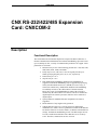
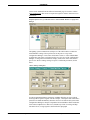
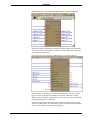
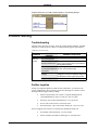
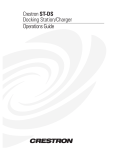
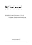
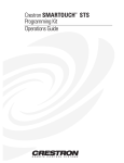
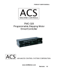
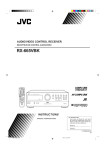
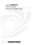
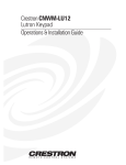
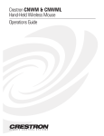
CRESTRON Contents CNX RS-232/422/485 Expansion Card: CNXCOM-2 1 Description .......................................................................................................................... 1 Functional Description ........................................................................................... 1 Physical Description............................................................................................... 2 Leading Specifications ......................................................................................................... 2 Setup.................................................................................................................................... 2 Installation ............................................................................................................. 2 Preparation for Use................................................................................................. 3 Programming with SIMPL™ Windows............................................................................. 4 How the Program Works ........................................................................................ 5 How to Create the Program..................................................................................... 5 Problem Solving................................................................................................................... 8 Troubleshooting ..................................................................................................... 8 Further Inquiries .................................................................................................... 8 Return and Warranty Policies............................................................................................... 9 Merchandise Returns / Repair Service .................................................................... 9 CRESTRON Limited Warranty .............................................................................. 9 Operations Guide - DOC. 8123 Contents • i CRESTRON CNX RS-232/422/485 Expansion Card: CNXCOM-2 Description Functional Description The CNXCOM-2 RS-232/422/485 Expansion Card provides RS-232, RS-422, or RS-485 communication with hardware and software handshaking. Speeds are rated up to 38,400 bps. In fact, a variety of communication parameters are support. Valid parameters are as follows. • Baud rates may be one of the following possible rates: 300, 600, 1200, 2400, 4800, 9600, 19200, and 38400. • Parity may be even, odd, none, or zero stick (parity bit always 0). When specifying the parity use E, O, N, or Z, respectively. • Data bits may be 7 or 8. • Stop bits may be 1 or 2. • Both XON/XOFF handshaking and RTS/CTS handshaking are supported. XON/XOFF handshaking may be supported by specifying XON (for both transmit and receive), XONR (for receive only), or XONT (for transmit only). XON/XOFF and RTS/CTS handshaking are mutually exclusive in the CNXCOM-2. If both are enabled, RTS/CTS is used. If CTS handshaking is enabled, the CTS line is monitored by the CNXCOM-2. The CTS line can also be enabled as a digital input to the control system; the RTS line can be enabled as a digital output. • Specify RS422 for standard if RS-422 compatible levels must be supported. • Break character of any length can be generated. • Supports RS-485. However, a specific protocol for defining the mechanism as to when a device is permitted to transmit on the RS-485 bus must be followed. To use this feature, use RS-422 communications settings. Set hardware handshaking to none. The RTS output can now be used to enable the transmitter. Notice that the receiver is always active. Therefore, transmissions are also received. Operations Guide - DOC. 8123 CNX RS-232/422/485 Expansion Card: CNXCOM-2 • 1 CRESTRON Physical Description The CNXCOM-2, shown below, is a circuit board fastened to an aluminum faceplate. The card is manufactured to easily fit into an unoccupied slot in a Crestron CNX Generation Control System. CNXCOM-2 Faceplate The faceplate contains two identical bidirectional DB9 male connectors. Silk screening is applied to the faceplate; connectors are labeled A and B. Leading Specifications The table below provides a summary of leading specifications for the CNXCOM-2. Dimensions and weight are approximations rounded to the nearest hundredth unit. Leading Specifications of the CNXCOM-2 SPECIFICATION Power Requirements SIMPL Windows CNX Operating System CNX Monitor Dimensions DETAILS 24 VDC, network power; 4 Watts Version 1.20.04 or later Version 5.01.21X or later Version 2.05X or later Height: 0.98 in (2.49 cm) Width: 5.00 in (12.70 cm) As of the date of manufacture, the unit has been tested and found to comply with specifications for CE marking. Setup Installation Items required to install the CNXCOM-2 are already attached to the unit. The only tools required are a Phillips tip screwdriver and a grounding strap. Follow the assembly procedure after this paragraph. CAUTION: The CNXCOM-2 contains electrostatic sensitive devices (ESD); observe precautions for handling ESDs to avoid damaging the card. NOTE: If installing the CNXCOM-2 into a CNMSX-AV, it is assumed that the CNXCAGE has been installed. 2 • CNX RS-232/422/485 Expansion Card: CNXCOM-2 Operations Guide - DOC. 8123 CRESTRON 1. Disconnect power from the CNMSX. 2. Use the Phillips tip screwdriver and remove two screws and blank faceplate from the control system. 3. Align the CNXCOM-2 with the card guides in the open slot and slide the expansion card into postion. 4. Firmly press both ends of the CNXCOM-2 faceplate to seat the expansion card into the control system connector. 5. Tighten the thumb-nail screws to secure the CNXCOM-2 to the control system. 6. Reapply power to the CNMSX. Preparation for Use Two distinct bidirectional serial ports are available from the CNXCOM-2 via two non-standard DB9 connectors. Refer to a sample hookup diagram below and aside from reapplying power to the control system last, complete the connections in any order. Sample Hookup Connections for CNXCOM-2 SERIAL DEVICE NOTE: The pinout of each 9-pin port is non-standard, therefore use of a straightthrough cable is not appropriate. The table following this note contains pinout descriptions for RS-232 as well as RS-422. Conflicts with some equipment may occur unless the controlled devices are properly wired. Certain devices have specific voltage requirements. Therefore, do not use all nine pins in a given application. Although the possibility is remote, improper wiring may result in damage to the controlled device. Only the required pins for each communication type should be connected. Non-Standard COM Pinout (for RS-232 and RS-422 Communication) PIN DIRECTION 1* 2 3 4 5 6 7 8 9 To CNXCOM-2 To CNXCOM-2 From CNXCOM-2 From CNXCOM-2 DESCRIPTION (RXD-) RS-422 Receive Data (Idles low) (RXD) RS-232 Received Data (TXD) RS-232 Transmitted Data (TXD+) RS-422 Transmit Data (Idles high) RS-232 and RS-422 Signal Common To CNXCOM-2 (RXD+) RS-422 Receive Data (Idles high) From CNXCOM-2 (RTS) RS-232 Request to Send To CNXCOM-2 (CTS) RS-232 Clear to Send From CNXCOM-2 (TXD-) RS-422 Transmit Data (Idles low) Where: * = RS-422 transmit and receive are balanced signals requiring two lines plus a ground in each direction. RXD+ and TXD+ should idle high (going low at start of data transmission). RXDand TXD- should idle low (going high at start of data transmission). If necessary, RXD+/RXDand TXD+/TXD- may be swapped to maintain correct signal levels. Operations Guide - DOC. 8123 CNX RS-232/422/485 Expansion Card: CNXCOM-2 • 3 CRESTRON A common application is to use a three-wire null modem serial cable to communicate with a PC, shown below. Since the pinout on the CNXCOM-2 is nonstandard, the card should not be plugged into the PC directly. The pinout in this illustration emulates the IBM PC AT connector except for the RS-422 signals on pins 1, 4, 6, and 9. Three-Wire Null Modem Serial Cable RXD 2 TO CNXCOM-2 TXD 3 GND 5 RED 3 TXD WHITE 2 RXD BLACK TO SERIAL DEVICE 5 GND 9-PIN FEMALE "D" CONNECTOR 9-PIN FEMALE "D" CONNECTOR NOTE: To support RS-485, tie pin 1 (RXD-) to pin 9 (TXD-) and pin 4 (TXD+) to pin 6 (RXD+) in the cable (refer to the table after this note). COM Pinout to RS-485 Bus COM (DB9) CONNECTOR RS-485 BUS Tie Pins 1 & 9 Tie Pins 4 & 6 Pin 5 + G Programming with SIMPL™ Windows SIMPL (Symbol Intensive Master Programming Language) is an easy-to-use programming language that is completely integrated and compatible with all Crestron system hardware. The objects that are used in SIMPL are called symbols. SIMPL Windows offers drag and drop functionality in a familiar Windows® environment. SIMPL Windows is Crestron Electronics' software for programming Crestron control systems. It provides a well-designed graphical environment with a number of workspaces (i.e., windows) in which a programmer can select, configure, program, test, and monitor a Crestron control system. The next two subsections describe a sample SIMPL Windows program that utilizes the CNXCOM-2. The first subsection details how the sample program works with a textual description and block diagram. The second subsection provides a broad description of how to actually create the SIMPL Windows program. NOTE: The following description assumes that the reader has knowledge of SIMPL Windows. If not, please refer to the extensive help information provided with the software. NOTE: There is no need to recreate the sample SIMPL Windows program. A copy of this program is available from Crestron’s ControlCD (version 4.03 and later). Search for the CNXCOM-2.SMW project in the SIMPL Windows Example Base. 4 • CNX RS-232/422/485 Expansion Card: CNXCOM-2 Operations Guide - DOC. 8123 CRESTRON How the Program Works A basic CNXCOM-2 SIMPL program is shown on the next page in block diagram form. For this example, the CNXCOM-2 occupies slot #1 of a CNMSX-PRO. Assume that a touchpanel is used to control the state of Zone 1 in a lighting system. Zone 1 can either be turned ON or OFF or can be ramped UP or DOWN. Block Diagram of CNXCOM-2 To turn the lights on, 9 bytes are sent (\x02Z-01-ON\x03). When join #1 on the touchpanel is pressed, the signal "Lights-Z1-On" goes high. When this signal goes high, the data is sent out the port to the lighting system. A similar approach is taken for "Lights-Z1-Off". These buttons have true feedback from the lighting system (i.e., when the 16 bytes (\x02Z-01-STATUS-ON\x03) enter the port, the digital signal "Lights-Z1-On-F" goes high and drives the feedback of join #1 high). In turn, this lights the feedback for the OFF button on the panel. In order to ramp the zone, the appropriate command is sent to start the ramping operation when the UP or DOWN button is pressed. When either button is released, the output of the NOR gate goes high. This, in turn, sends the STOP command to the lighting system, telling it to halt the ramping operation in progress. It is important to note that the user does not have to define the [TX$] or [RX$] for the port. If strings are being triggered and matched only in the port, the string assignment is taken care of by the compiler. If the TX$ is defined, it can be driven by other string creation symbols (i.e., an Analog to Serial or speed key: TXA). If RX$ is defined, it can be routed to other string processing symbols (i.e. Serial Gather or speed key: GATHER). Another typical usage would be if a macro were to drive the port, then the TX$ and RX$ would come from/go to the macro definition. Refer to the help file in SIMPL Windows. From the Contents search on Symbol Card File or from the Index search on the names of the symbols for details. How to Create the Program Use the Configuration Manager workspace in SIMPL Windows to select and configure all the devices that need to be included into the system. For this example, add a CNXCOM-2 to slot #1 of the CNMSX-PRO. Also add a CT-3500 to the system; its NET ID must be set to 03, shown on the next page. NOTE: SIMPL Windows v1.20.04 or later is required to program the CNMSXPRO with a CNXCOM-2 card. If using an earlier version of SIMPL Windows, Crestron recommends a SIMPL Windows and operating system upgrade. The latest Operations Guide - DOC. 8123 CNX RS-232/422/485 Expansion Card: CNXCOM-2 • 5 CRESTRON version can be obtained from the Software Downloads page of Crestron’s website (www.crestron.com). New users are required to register in order to obtain access to the FTP site. Graphical System View of CNXCOM-2 and CT-3500 in SIMPL Windows’ Configuration Manager The lighting system communicates with port A of the CNXCOM-2 over RS-422 with 38400 N81 settings. These preferences for the port are set up in the Configuration Manager. Click on the CNXCOM-2 in slot #1 of the CNMSX-PRO to display the ports of the card in the Detail System View area of the Configuration Manager. To assign the forementioned settings, double click on the white field in port A. The “Device Settings” dialog box opens. Confirm the parameters, shown below. “Device Settings” Dialog Box Use the Programming Manager workspace in SIMPL Windows to select symbols and assign their respective signals. For this example, a touchpanel and CNXCOM-2 symbols were added automatically when the devices were added to the system in the Configuration Manager workspace. Expand the Network Modules folder and double click on the touchpanel for a detail view (alternatively CTRL+D or drag and drop into Detail View). Assign signals as shown after this paragraph. 6 • CNX RS-232/422/485 Expansion Card: CNXCOM-2 Operations Guide - DOC. 8123 CRESTRON Graphical Detail View of Touchpanel in SIMPL Windows’ Programming Manager Expand the Central Control Modules and Slot-01 folders. Double click on the Port A icon for a detail view (alternatively CTRL+D or drag and drop into Detail View). Assign signals as shown below. Graphical Detail View of CNXCOM-2 in SIMPL Windows’ Programming Manager In this example, all commands are suffixed with the hex byte \x03. To save some typing, \x03 can be entered as the delimiter in the CNXCOM-2 Port A symbol. When present, the delimiter is appended to every string of text in the port definition (both transmitted and received strings). Expand the Logic folder to display the NOR symbol integrated into this program. View the symbol in detail view (alternatively CTRL+D or drag and drop into Detail View). Assign signals as shown after this paragraph. Operations Guide - DOC. 8123 CNX RS-232/422/485 Expansion Card: CNXCOM-2 • 7 CRESTRON Graphical Detail View of a NOR in SIMPL Windows’ Programming Manager Problem Solving Troubleshooting The table below provides corrective action for possible trouble situations. If further assistance is required, please contact a Crestron technical support representative. CNXCOM-2 Toubleshooting TROUBLE CNXCOM-2 does not function. POSSIBLE CAUSE(S) CORRECTIVE ACTION CNX Control System is Verify power to CNX Control System. not receiving power. Circuit card is not Verify CNXCOM-2 is properly inserted into properly seated in slot. CNX Control System slot per procedures in this Operations Guide. Cable from CNXCOM-2 Verify wiring. Connect only the required pins to controlled equipment for each communication type. is incorrect. Incorrect serial port Verify the communication parameters settings. assigned in the "Device Settings" dialog box as described in the Programming section. Programming error. Check SIMPL Windows program. Further Inquiries If after reviewing this Operations Guide for the CNXCOM-2, you cannot locate specific information or have questions, please take advantage of Crestron's award winning technical support team by calling: • In the US and Canada, call Crestron’s corporate headquarters at 1-888-CRESTRON [1-888-273-7876] or 1-201-767-3400. • In Europe, call Crestron International at +32-15-50-99-50. • In Asia, call Crestron Asia at +852-2341-2016. • In Latin America, call Crestron Latin America at +525-574-15-90. For local support from exclusive Crestron factory-trained personnel call: • In Australia, call Soundcorp at +613-941-61066. • In New Zealand, call Amber Technologies at +649-410-8382. 8 • CNX RS-232/422/485 Expansion Card: CNXCOM-2 Operations Guide - DOC. 8123 CRESTRON Return and Warranty Policies Merchandise Returns / Repair Service 1. 2. 3. No merchandise may be returned for credit, exchange, or service without prior authorization from CRESTRON. To obtain warranty service for CRESTRON products, contact the factory and request an RMA (Return Merchandise Authorization) number. Enclose a note specifying the nature of the problem, name and phone number of contact person, RMA number, and return address. Products may be returned for credit, exchange, or service with a CRESTRON Return Merchandise Authorization (RMA) number. Authorized returns must be shipped freight prepaid to CRESTRON, Cresskill, N.J., or its authorized subsidiaries, with RMA number clearly marked on the outside of all cartons. Shipments arriving freight collect or without an RMA number shall be subject to refusal. CRESTRON reserves the right in its sole and absolute discretion to charge a 15% restocking fee, plus shipping costs, on any products returned with an RMA. Return freight charges following repair of items under warranty shall be paid by CRESTRON, shipping by standard ground carrier. In the event repairs are found to be non-warranty, return freight costs shall be paid by the purchaser. CRESTRON Limited Warranty CRESTRON ELECTRONICS, Inc. warrants its Cresnet II products, denoted by a "CN" prefix model number, to be free from manufacturing defects in materials and workmanship for a period of three (3) years from the date of shipment to purchaser. Disk drives and any other moving or rotating mechanical parts are covered for a period of one (1) year. CRESTRON warrants all its other products for a period of one year from the defects mentioned above, excluding touchscreen display components which are covered for 90 days. Incandescent lamps are completely excluded from Crestron's Limited Warranty. CRESTRON shall, at its option, repair or replace any product found defective without charge for parts or labor. Repaired or replaced equipment and parts supplied under this warranty shall be covered only by the unexpired portion of the warranty. CRESTRON shall not be liable to honor warranty terms if the product has been used in any application other than that for which it was intended, or if it has been subjected to misuse, accidental damage, modification, or improper installation procedures. Furthermore, this warranty does not cover any product that has had the serial number altered, defaced, or removed. This warranty shall be the sole and exclusive remedy to the purchaser. In no event shall CRESTRON be liable for incidental or consequential damages of any kind (property or economic damages inclusive) arising from the sale or use of this equipment. CRESTRON makes no other warranties nor authorizes any other party to offer any warranty, expressed or implied, including warranties of merchantability for this product. This warranty statement supersedes all previous warranties. NOTE: All brand names, product names, and trademarks are the property of their respective owners. Windows and Windows95 are the property of Microsoft Corp. Operations Guide - DOC. 8123 CNX RS-232/422/485 Expansion Card: CNXCOM-2 • 9