1
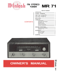
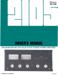
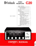
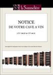
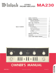
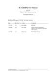
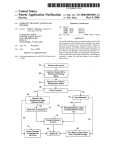
STEREO
PREAMPLIFIER
C22
GENERAL DESCRIPTION
1
TECHNICAL DESCRIPTION
Mechanical Specifications
Electrical Specifications
1
2
2
FRONT PANEL INFORMATION
3
OPERATING INSTRUCTIONS
8
8
8
9
9
10
11
11
11
GUARANTEE
16
3-YEAR FACTORY SERVICE CONTRACT
16
INSTALLATION
CONTENTS
CONNECTIONS
AC Connections
AC Power
Input Connections
Output Connections
Loudspeaker Phasing Connections
Ground Connection
OWNER'S MANUAL
C 22
C22 STEREO PREAMPLIFIER
GENERAL DESCRIPTION
The Mclntosh C22 Stereophonic Preamplifier is a control center for any stereophonic
sound system. To increase your enjoyment of
stereo, this control center does four jobs with
precise control.
First, the control center amplifies weak
electrical impulses. As the record rotates on
the turntable, undulations in the grooves
move the pickup stylus approximately one
thousandth of an inch, in any direction, from
the rest position. From this slight mechanical
movement, the pickup stylus generates a
weak electrical impulse on the order of a few
thousandths of a volt. To amplify and preserve the information in such an electrical
impulse, the finest amplifier performance is
required.
Second, every sound system is used in a
different acoustical environment. The tone
balance of the music is affected by variations
in environment. Also, people listening to the
music have varying ideas of correct tone balance. To compensate for these conditions, a
high-quality tone control center is needed.
Third, all stereophonic and monophonic
records, both domestic and foreign, are
recorded with specific frequency equalization. The control center must accurately compensate for this equalization introduced in
the recording process.
Fourth, programs can originate from several sources such as tuners, records, tape
machines, microphones, etc. A control center
is needed to select and switch these sources
separately or in combination.
All of these jobs are performed with excel-
lence by the C22.
The C22 also uses the new, exclusive
Mclntosh PANLOC method of installation.
The PANLOC system gives you absolute ease
of installation, operation, and maintenance.
PANLOC is the first professional installation
technique to be used on stereo instruments.
In the PANLOC system a metal shelf is
mounted first, then the preamplifier slides
into position on this shelf. Depressing the
PANLOC buttons on the front panel locks the
preamplifier firmly into place for normal
operation. To unlock the preamplifier, depress the front panel PANLOC buttons a
second time. The preamplifier can now slide
forward to the ADJUST position. The preamplifier will lock in this position approximately 3 inches from the mounting panel.
Now you can adjust the output level controls,
low frequency trim controls, tape equalization controls, phase switch and pilot lamp
intensity switch. These controls are mounted
just behind the C22 front panel. Depressing
the ADJUST position holding latches on the
sides of the chassis allows the preamplifier
to be taken out of the PANLOC shelf, or to
slide back into position against the mounting
panel.
Once you have enjoyed the outstanding
performance of the C22, you will understand
why Mclntosh products have earned their
reputation as "THE BEST." Your Mclntosh
C22 Stereophonic control preamplifier will
give you years of the finest possible performance, and will become a highly valued part of
your home music system.
TECHNICAL DESCRIPTION
The C22 Stereophonic Preamplifier combines excellence in performance with ease of
operation. The most often used controls have
large diameter knobs. A new type of rocker
switch is used for the controls with simple
on-off functions. The C22 has an illuminated
front panel with a light intensity switch to
provide convenient reading under low-level
lighting conditions. The Mode and Input
Selector switch positions are also illuminated.
The C22 circuit consists of 3 amplifier
sections in duplicate for the left and right
stereo channels together with a common
power supply. The first amplifier section is
1
the input preamplifier used to amplify and
equalize signals from phonograph pickups,
microphones or tape heads. Skillful circuit
layout, proper grounding, and adequate
shielding reduce the hum so low it is virtually
unmeasurable. Extreme care in manufacturing combined with low noise tubes, high
specific resistivity circuit boards, metal film
and wire wound resistors achieves new low in
residual noise.
The second amplifier section follows the
main volume control, making it impossible to
overload the high level input circuits or any
following circuits. The same design techniques as used in the preamplifier section
assure low noise and hum. The BASS and
TREBLE feedback-type tone controls operate
in connection with this amplifier section. The
controls are switch-type with approximately
4 db change per step. Exceedingly low distortion and precise control of frequency response contours are assured using this
arrangement.
Front panel tape jacks are provided for
convenient use of an external tape machine.
The TAPE JACK switch connects the jacks for
either playback or recording through the C22.
The third section is the cathode follower
output. The sharp cutoff (18 db per octave)
RUMBLE and HF (high frequency) filters are
associated with this section. OUTPUT LEVEL
controls are located at the inputs of the cathode followers to allow simple balance of the
entire amplifier-speaker system. The OUTPUT LEVEL controls are located on top of the
C22, behind the front panel. These controls
are conveniently accessible by releasing the
PANLOC buttons and sliding the C22 out to
the adjust position.
The power supply deserves special mention. The power transformer is constructed
with "core" type grain oriented laminations
and magnetic shielding for low external humfields. Long life rectifiers with full wave
rectification, filter condenser sectionalizing
and careful grounding add to the hum-free
long life characteristics of the C22.
Special attention has been given to the
mechanical design. The PANLOC system is
the first professional installation technique
to be used on stereo instruments. The
PANLOC system gives you absolute ease of
installation, operation and maintenance. The
C22 may be conveniently installed in furniture cabinets, custom-built installations, professional relay racks or an attractive finished
Mclntosh cabinet.
MECHANICAL SPECIFICATIONS
Size:
Front panel; 16 inches wide by 57/16 inches
high; chassis (including PANLOC shelf) 15
inches wide by 5 inches high by 13 inches
deep, including connectors; clearance in
front of mounting panel including knobs,
1½ inches.
Weight:
16 pounds net, 25 pounds in shipping carton.
Finish:
Anodized gold and black (front panel).
ELECTRICAL SPECIFICATIONS
Power Requirement:
117 volts 50/60 cps AC, 34 watts.
Frequency Response:
±0.5 db from 20 cps to 20,000 cps.
Input Sensitivity and Impedance:
Auxiliary, Tape, Tuner 1, and Tuner 2: 0.25
volts, 250,000 ohms.
Phono 1 and Phono 2: 2 millivolts, 47,000
ohms.
Microphone: 2.5 millivolts, 1 megohm.
Tape Head: 2 millivolts, 1 megohm.
Tape Compare: 0.25 volts, 250,000 ohms.
Distortion:
Less than 0.2% at 10 volts output.
Less than .02% at 3 volts output.
2
Total Noise:
High Level Inputs: 85 db below rated output.
Low Level Inputs: Less than 1.5 microvolts at
input terminals.
Main Output:
2.5 volts with rated input.
Treble Controls:
Separate channel 11 position switch type,
± 20 db at 20,000 cycles.
Tape Output:
.25 volts with rated input.
Left Plus Right Output:
1 volt from generator impedance of 25,000
ohms.
Voltage Amplification:
Auxiliary, Tape, Tuner 1, and Tuner 2:
To Main Output, 20 db (10 to 1).
To Tape Output, 0 db (1 to 1).
Phono 1 and Phono 2 (At 1 KC):
To Main Output, 62 db (1250 to 1).
To Tape Output, 42 db (125 to 1).
Microphone:
To Main Output, 60 db (1000 to 1).
To Tape Output, 40 db (100 to 1).
Tape Head (At 500 cps):
To Main Output, 62 db (1250 to 1).
To Tape Output, 42 db (125 to 1).
A.C. Outlets:
1 unswitched (Red) for turntable or tape
machine.
4 switched.
Tubes:
6 each 12AX7.
Tape Jack Switch:
2 position, connects panel jacks to allow
signals to be fed from or to the C22 to
record or playback using an external
portable tape recorder.
Bass Controls:
Separate channel 11 position switch type,
±20 db at 20 cycles.
Compensator Switch:
RIAA or LP record equalization.
Tape Switch:
Normal, or Tape Monitor.
Rumble Filter:
50 cps cutoff.
HF Filter:
5000 cycle cutoff.
Additional Set-Up Controls:
The following controls are located behind the
front panel on the top of the C22 chassis.
These controls are readily accessible by
depressing the PANLOC buttons to slide
the C22 forward from the mounting panel:
Output Level Controls (L, L + R, and R):
Allows the balance of the entire system to
be conveniently adjusted.
Low Frequency Trim Controls (L and R):
Allows frequencies below 100 cps to be
boosted up to 6 db to compensate for
unequal speaker response.
Tape Equalization Controls (L and R):
Adjusts tape head input high frequency
response.
Phase Switch:
2 position, normal (0°) or reverse (180°).
Pilot Lamp Intensity Switch:
2 position, bright or dim.
FRONT PANEL FACILITIES
Figure 1. C22 Front Panel.
3
INPUT SELECTOR
Figure 2. INPUT SELECTOR switch.
Select any one of eight program sources
with this switch:
1. AUX: any auxiliary service requiring flat
amplification, such as a television set, is
connected to the C22 through the AUX
position.
2. TAPE: any self-contained tape machine
(tape machine having its own playback
preamplifier) is connected to the C22
through the TAPE position.
3. TUNER 1: AM and FM or MPX FM outputs
from a stereo tuner are connected to the
C22 through the TUNER 1 position.
4. TUNER 2: same as TUNER 1.
5. PHONO 1: connects the C22 for stereo
and monophonic operation for records.
6. PHONO 2: same as PHONO 1.
7. MIC: stereo microphones are connected
to the C22 through the MIC position.
8. TAPE HD: a tape deck that does not contain its own playback preamplifier is connected to the C22 through the TAPE HD
position.
1.
2.
3.
4.
5.
6.
7.
Use the MODE SELECTOR to:
Listen to normal stereo (4 following
and page 13.
Reverse the left and right arrangement
of musical instruments (3 following
and page 12).
Balance the amplifiers and loudspeakers in a stereo system (6 and 7 following and page 11).
Listen to monophonic sound (1 and 2
following and page 13).
Listen thru both loudspeakers to either
track of a stereo program source (1 and
2 following and page 13).
Turn the MODE SELECTOR to:
L TO L & R: connects the "left" input to
both loudspeakers.
R TO L & R: connects the "right" input to
both loudspeakers.
STEREO REV: connects the "left" input to
the "right" loudspeaker and the "right"
input to the "left" loudspeaker.
STEREO: connects the "left" input to the
"left" loudspeaker and the "right" input
to the "right" loudspeaker.
MONO (L + R): adds the "left" input and
the "right" input and then connects the
L + R program to both amplifiers and
loudspeakers.
L + R TO L: connects the "left plus right"
programs to the "left" loudspeaker only.
L -I- R TO R: connects the "left plus right"
programs to the "right" loudspeaker only.
VOLUME
MODE SELECTOR
Figure 4. VOLUME control.
Figure 3. MODE SELECTOR switch.
4
Use the VOLUME control to regulate the
combined volume level of both channels.
Turning the VOLUME control clockwise increases volume level.
BALANCE CONTROL
Figure 5. BALANCE CONTROL.
Use the C22 BALANCE control to balance
unequal volume in the left and right channels
of a program source. The volume of each
speaker system relative to the other can be
varied, at the same time their combined
volume level is maintained.
LEFT . . . turning the control to the left
accents the left channel by reducing the right
channel output.
RIGHT . . . turning the control to the right
accents the right channel by reducing the
left channel output.
TREBLE CONTROLS
Figure 7. TREBLE CONTROLS.
Use the LEFT and RIGHT TREBLE CONTROLS to regulate treble loudness to the left
and right speakers, respectively. Clockwise
rotation increases treble loudness; counterclockwise rotation decreases treble loudness.
Each switch step of the TREBLE Control
changes treble loudness approximately 4 db.
COMP (COMPENSATION)
BASS CONTROLS
Figure 8. COMP (COMPENSATION) switch,
Use the COMP switch to correct for phono
equalization introduced by the recording
process. All current LP and Stereo recordings
use RIAA equalization. Some stereo and
early mono recordings use LP equalization.
Figure 6. BASS CONTROLS.
Use the LEFT and RIGHT BASS CONTROLS to regulate bass loudness to the left
and right speakers, respectively. Clockwise
rotation increases bass loudness; counterclockwise rotation decreases bass loudness.
Each switch step of the BASS control changes
bass loudness approximately 4 db.
TAPE JACKS
Use the C22 TAPE JACKS to hear a program originating from a portable tape machine or to record a program picked up by the
C22 on a portable tape machine.
RECORD ... . connects signals from the
rear tape jacks to the INPUT SELECTOR
TAPE position. Any program picked up by
the C22 is connected to the portable machine
5
for recording.
PLAYBACK . . . TAPE input is switched
from rear tape jacks to front panel telephone
jacks (left tape and right tape). Any program
originating from a portable machine connected to the C22 can be heard by rotating
the INPUT SELECTOR to the TAPE position.
LEFT TAPE . . . telephone jack female
receptacle for the left channel of a portable
tape machine.
RIGHT TAPE . . . telephone jack female
receptacle for the right channel of a portable
tape machine.
RUMBLE
Figure 10. RUMBLE filter switch.
TAPE
Use the C22 RUMBLE filter to reduce lowfrequency noise created by a turntable or
record changer and acoustically coupled
feedback.
FLAT . . . filter disconnected.
FILTER . . . low-frequency rumble noise
below 50 cps created by a turntable or
record changer and acoustically coupled
feedback are reduced when the RUMBLE
filter button is pushed to the FILTER position.
Figure 9.
TAPE switch.
Use the C22 TAPE switch to know instantaneously, as you are recording, that the
music on the tape is acceptable. The C22
TAPE switch makes it possible to instantaneously compare recorded material with the
source signal. Tape jacks on the back panel
accept a signal from a tape recorder with a
monitor head and preamplifier.
NORMAL . . . the program source is fed
through the power amplifiers and the loudspeakers.
MONITOR . . . the signal source becomes
the monitored program from the recorded
tape and is fed through the power amplifiers
and loudspeakers.
POWER
The C22 and four black receptacles on
the back panel are turned on and off by the
POWER switch.
.6
H.F. (HIGH-FREQUENCY FILTER)
Figure 11. H.F. (High-Frequency Filter) switch.
This switch minimizes surface noise when
reproducing old, badly worn recordings.
FLAT . . . filter disconnected.
FILTER . . . rolls off response sharply at
5 KC.
this position, additional controls on top of the
C22 chassis are available; the PHASE switch,
LOW FREQUENCY TRIM CONTROLS, OUTPUT LEVEL CONTROLS, TAPE EQUALIZATION CONTROLS, and the PILOT LAMP
INTENSITY switch.
LOUDNESS
PILOT LAMP INTENSITY
Use the PILOT LAMP INTENSITY to switch
the front panel pilot lamps to DIM or BRIGHT.
Figure 12. LOUDNESS switch.
Use the LOUDNESS switch in the COMPENSATED position to listen at low volume
and still hear full-frequency range. When you
turn down the volume, the music will seem to
lose much of its bass and some of its treble.
This effect is due to the sensitivity characteristics of human hearing. The response of the
human ear to bass and treble pitch decreases more rapidly than its response to
notes centered in the midtonal range. The
LOUDNESS switch automatically provides
the correct amount of bass and treble boost
required to compensate for this change in
response of the human ear at low-loudness
levels. When the LOUDNESS switch is moved
to the COMPENSATED position, it converts
the volume control to a loudness compensated control.
CONTROLS BEHIND THE FRONT PANEL
TAPE EQUALIZATION
Use the TAPE EQUALIZATION controls to
compensate for 3% tape speed for individual
tape head characteristics. These controls
should be set to NAB for normal 7.5 inch
tape speed machines. Turning the TAPE
EQUALIZATION controls clockwise increases
the treble response; turning them counterclockwise decreases treble response.
OUTPUT LEVEL CONTROLS
Use the OUTPUT LEVEL controls to balance the overall amplifier-speaker system.
The minimum setting on each control reduces the output level approximately 15 db.
The L + R (left plus right) control adjusts only
the output from the L + R output jack. This
control can turn the L + R signal completely off.
LOW FREQUENCY TRIM CONTROLS
Use these controls to adjust for unequal
speaker response at low frequencies due to
room location of speakers. Approximately
6 db of boost below 100 cycles is available.
Depressing the PANLOC buttons allows
the C22 to slide forward to a point approximately 3 inches from the mounting panel. In
Figure 13. Controls Behind the Front Panel.
7
PANLOC BUTTONS
At the bottom front corners are the
PANLOC buttons. After a preamplifier is
installed on the PANLOC shelf, depressing
the PANLOC buttons will lock the preamplifier firmly in position. Depressing the PANLOC
buttons a second time (as with a ball-point
pen) will release the preamplifier. The pre-
amplifier can then be slid forward to the
inspection and adjustment position. Releasing the ADJUST position latches allows you to
slide the preamplifier completely out of its
mounting shelf, or back into normal operating position. The PANLOC system gives you
absolute ease of installation, operation and
maintenance.
INSTALLATION
The C22 can be installed in conventional
furniture cabinets, custom built installations
or professional relay racks. If the unit is to be
placed on a shelf or table-top, it is recommended that it be housed in a Mclntosh
cabinet. The C22 installs conveniently from
the front of the cabinet by sliding into its
PANLOC shelf.
To support the weight of the C22, the
wood panel used to mount it should be at
least ¼ inch thick.
The C22 installation should allow approximately 14 inches behind the front panel to
mount the PANLOC shelf and allow for connecting wires. To allow sufficient space for
the circulating air, the desirable minimum
internal cabinet dimensions should be 16
inches and 5½ inches respectively.
CONNECTING
AC CONNECTIONS
There are five AC outlets on the rear panel
of the C22(See Figurel4.) These receptacles
have a maximum rating of 660 watts total.
The power to the four black receptacles is
controlled by the POWER switch on the front
panel. The red receptacle is not switched.
The red receptacle is used for powering a
turntable or record changer. The receptacle
is not switched so that the turntable power
will not be turned off while the turntable idler
wheel is engaged. The turntable is protected
by this arrangement because it is necessary
to turn off the turntable with its own control
switch so that no damage will result to the
turntable drive system.
Figure 14. A-C Connections.
8
AC POWER
Plug the AC power cord in 105 volt to 125
volt, 50 to 60 cycle power line. The power
used by the C22 is 34 watts.
INPUT CONNECTIONS
The C22 provides eight separate program
inputs controlled by the I N P U T SELECTOR
switch. One input for tape monitor or tape
comparison is controlled by the TAPE switch.
The input program connections should be
made in accordance with Table 1.
Figure 15. INPUT CONNECTIONS.
CONNECTION
TAPE MONITOR
(COMPARE)
AUX
FUNCTION
INPUT
SENSITIVITY
INPUT
IMPEDANCE
0.25V
250K
0.25V
250K
The tape monitor input accepts a signal from a tape
recorder with a monitor head and preamplifier
The auxiliary input accepts any auxiliary service requiring flat frequency response, such as a T.V. set, tuner,
tape recorder with its own playback preamplifier, etc.
The tape input operates with tape machines containing
their own playback preamplifier
The tuner inputs accept AM and FM outputs from a
stereo tuner or a pair of stereo tuners or the multiplex
output of an adapter of multiplex tuner
0.25V
250K
0.25V
250K
CONNECTION
FUNCTION
INPUT
SENSITIVITY
INPUT
IMPEDANCE
PHONO 1 & 2
MAGNETIC
TAPE HEAD 1 & 2
2-10 MV
MIC
These jacks are to be used with magnetic cartridges. . .
2 MV
47K
2 MV
1 megohm
2.5 MV
1 megohm
TAPE
TUNER 1 &
TUNER 2
These jacks are to be used with a tape deck that does
not contain its own playback preamplifier
These jacks are to be used with high impedance crystal
or dynamic microphones
If a phono cartridge requires less than
47,000 ohms load impedance, a resistor can
be added across the terminals of the carDesired Impedance
47,000 ohms (47K)
37,000 ohms (37K)
27,000 ohms (27K)
15,000 ohms (15K)
6,800 ohms (6.8K)
tridge to achieve the correct termination.
The following chart may be used as a guide:
Resistor Across Input
No Resistor
180,000 ohms (180K)
62,000 ohms (62K)
22,000 ohms (22K)
8,200 ohms (8.2K)
9
Figure 16. Turntables feeding low-level inputs.
OUTPUT CONNECTIONS
There are two sets of outputs on the left
half of the back panel. (See Figure 15) One
pair is marked M A I N . The second pair is
marked TAPE.
The M A I N outputs connect to power
amplifiers (figure 17). The TAPE output feeds
a tape recorder.
The MAIN jacks are fed from cathode
followers. Longer cables than are normally
supplied can be connected between the C22
and the amplifiers. The length of the cable is
limited by the capacity of the cable. The total
capacity must not exceed 1000 mmf. For
instance: cables with a capacity of 25 mmf
per foot may be 40 feet long; 13.5 mmf per
foot cable may be 75 feet long. The input
impedance of the amplifiers should be
50,000 ohms or greater.
The TAPE output is fed from a cathode
follower. The program material fed out of the
TAPE output is not affected by these front
panel controls: VOLUME control, BASS controls, LF and HF filter switches, BALANCE
control, LOUD switch, TAPE switch, PHASE
switch, TREBLE controls, and MODE SELECTOR switch.
The program material fed out of the TAPE
output is affected by these front panel con-
Figure 17. MAIN OUTPUT Connected to
Power Amplifiers.
10
trols: I N P U T SELECTOR positions, AUX,
TAPE, TUNER 1, T U N E R 2, or MIC, the
MUTING switch and T U N I N G control. When
the INPUT SELECTOR is turned to TAPE HD
then the COMP should be set to R I A A .
The input impedance of the tape recorder
should be 50,000 ohms or greater.
A jack marked L + R OUTPUT is located
next to M A I N OUTPUTS.
A monophonic signal can be distributed to
other rooms by connecting another power
amplifier to the jack marked L + R. The cable
connecting this output to the amplifier should
not have a capacity of more than 1000 mmf.
The i n p u t impedance of the power amplifier
connecting to this output should not be less
than 150.000 ohms (150K).
LOUDSPEAKER PHASING CONNECTIONS
Two pairs of screw terminals are located
on the lower left section of the C22 back
panel. The speaker leads from the "left"
power amplifier should be connected to the
screw terminals marked FROM A M P L I F I E R .
The pair of terminals marked TO SPEAKER
should be connected to the "left" loudspeaker.
These connections allow the front panel
PHASE switch to reverse the phase on the
left loudspeaker. This arrangement is convenient when setting up a stereo system.
GROUND CONNECTION
A single ground post is provided. The
chassis ground from turntable, record changers (motors used with each), tape decks,
etc., should be returned to this post. Do not
duplicate this ground circuit. H u m is likely to
be heard in the system if duplicate ground
returns are used.
The left and right program cables from
each source should be twisted together and
the ground wire from each source can be
wound or twisted in with these cables. To
avoid hum, make sure the ground wire does
not make any connections to shields of the
left and right channel cables except for the
connection provided with the C22 ground post.
OPERATING INSTRUCTIONS
BALANCING A STEREO SYSTEM
The performance and enjoyment of a
stereo system is greatly increased when the
system is properly balanced. There are two
factors that require balancing. One is the
unequal program loudness on the left and
right channels of a program source. The control marked BALANCE on the C22 is used to
balance unequal program loudness. Balancing a program for unequal loudness is explained under ADJUSTING BALANCE CONTROL TO CORRECT PROGRAM MATERIAL.
The other factor that requires balancing is
system balance. The balance of the stereo
system is affected by many things including
room acoustics, f u r n i t u r e placement, room
shape, small differences in loudspeakers,
etc. Balancing the system is done by adjusting the controls on the power amplifiers.
To begin balancing the system, check to
see that the controls on the amplifier are
properly set. If the amplifier is a Mclntosh
MC225, set the input switch to STEREO. Turn
both input level controls to the black dot at
the 12 o'clock position of the control.
If the a m p l i f i e r is a Mclntosh MC240 or
MC275 check to see that the cables from the
C22 are plugged into the STEREO I N P U T
jacks. Then set the lever switch to STEREO.
Turn the BALANCE control to the 0 mark at
the 12 o'clock position of the control. The
amplifiers are now ready for the rest of the
steps to balancing the system.
1. Play a f a m i l i a r recording on the record
player.
2. Push the two PANLOC buttons to release
the C22 from the mounting shelf. Pull the
C22 toward you until the latch locks engage approximately 3 inches from the
front panel.
3. Turn the I N P U T SELECTOR to the
PHONO position into which the record
player is connected.
4. Turn the BASS CONTROLS and TREBLE
CONTROLS so that the knob indicators
are centered between the panel markings L and R.
5. Turn the BALANCE control to the center
or 12 o'clock position.
6. Place the LOUDNESS switch in the
11
COMPENSATED position.
7. Place the TAPE switch in the MONITOR
position.
8. Place the PHASE switch in the 0° position.
9. Place the RUMBLE filter switch in the
FLAT position.
10. Place the H.F. cutoff filter switch in the
FLAT position.
11. Turn the MODE SELECTOR to the L + R
TO L position.
12. While the program is playing, alternate
the MODE SELECTOR between the L + R
TO R and the L + R TO L position. On
amplifiers such as the MC225, adjust the
correct gain control until the loudspeakers are of equal loudness. On the MC240
or the MC275, turn the balance control
u n t i l the loudspeakers are of equal
loudness.
The stereo system is now balanced. It will
remain balanced through all modes of operation. Leave the C22 extended on its PANLOC
stops for the next series of adjustments.
ADJUSTING PHASE
1. Set the MODE SELECTOR to STEREO.
2. Turn the BASS controls and T R E B L E
controls to straight up position so that the
dial indicator centers between the panel
markings L and R.
Stand approximately 10 feet in front of
and midway between the loudspeakers. The
source of sound should appear to be directly
in front of you. Alternate the PHASE switch
between 0° and 180°. If the sound is not
directly in front of you in the 0° position,
reverse the leads to one loudspeaker. The
PHASE control is used to correct phase in
the source material whenever necessary.
ADJUSTING BALANCE CONTROL AFTER
THE SYSTEM HAS BEEN BALANCED
When these instructions have been completed, the overall system is balanced and in
phase; ready to deliver maximum pleasure
and enjoyment.
You may hear differences in balance from
one record to another or from one tape to
another. Some records or tapes may be
recorded with slight differences between
channels. The differences can be corrected
with the BALANCE control on the front panel.
If the difference is heard on every record,
then the cartridge may have a very small
difference in output.
12
ADJUSTING FOR SPECIAL EFFECTS
HF CUTOFF FILTER
If you wish to reproduce old, badly worn
records, you can minimize the surface noise
by switching the HF cutoff filter to the IN
position.
RUMBLE FILTER
If you are using a turntable or changer
which has low-frequency rumble noise, you
may reduce it by pushing the R U M B L E filter
switch to the FILTER position.
BASS CONTROLS AND TREBLE CONTROLS
The tone balance which you hear when
listening to an orchestra is affected by the
conductor's instructions to his musicians,
the acoustical environment in which you are
listening, and your own subjective hearing
interpretation. Considering these conditions,
it is easy to see why tone balance controls
play a major role in correcting for the following factors:
1. Each person's subjective idea of tone
balance.
2. Loudspeaker frequency response characteristics.
3. Loudspeaker placement in the listening
room.
4. The conductor's idea of tone balance at
the time the recording was made.
5. The microphone frequency response characteristics.
6. The recording process influences.
These factors can be considered as
environmental influences. The BASS CONTROLS and TREBLE CONTROLS provide a
degree of compensation for effects of environment. Listen to your system with each
control set with the indicators centered
between the panel markings L and R. If you
wish to reduce treble in relation to bass for
example, turn the T R E B L E CONTROLS counterclockwise until the tone balance sounds
correct to you. These controls will modify
tone balance without i n t r o d u c i n g any u n d e sirable effects. Do not be surprised if you
find your preference in tone changing from
time to time.
LOUDNESS
Due to a selective shift in sensitivity of
human hearing, music reproduced at very
low volume loses its bass and treble.
The LOUDNESS switch on the C22 changes
the VOLUME control to a loudness compensated control to correct for this effect.
When you wish to listen to music at a greatly
reduced loudness level and yet hear bass and
treble in their proper relationships, set the
LOUDNESS switch to the IN position.
PHASE
If the stereo sound seems to come from
either side of the room instead of being distributed between the loudspeakers, adjust
the PHASE control to 180°. This listening
effect is due to reproducing sound that is out
of phase from one channel to the other. You
will find some records differ from others in
this respect and that some tapes differ from
records.
LISTENING TO A STEREO TUNER
1. Turn the INPUT SELECTOR to TUNER
1 or TUNER 2.
2. Turn the MODE SELECTOR to STEREO.
3. Set the PHASE switch to 0°.
4. Set the H.F. cutoff filter switch to FLAT.
(See page 12 ADJUSTING FOR SPECIAL
EFFECTS.)
5. Set the R U M B L E filter switch to FLAT.
(See page 12 ADJUSTING FOR SPECIAL
EFFECTS.)
6. Set the LOUDNESS switch to NORMAL.
(See page 12 ADJUSTING FOR SPECIAL
EFFECTS.)
7. Turn the BASS CONTROLS and TREBLE
CONTROLS so that the indicators are
centered between the panel markings
L and R. (See page 12 BASS AND TREBLE
CONTROLS.)
8. Set the TAPE switch to NORMAL.
9. Adjust the VOLUME control to the desired
volume.
After a warm up of about 30 seconds, turn
the tuning knob on your tuner to find the
station of your choice.
LISTENING TO A STEREO RECORD
To listen to stereo records, proceed as
follows:
1. Turn the INPUT SELECTOR to PHONO 1
or PHONO 2, whichever is connected to
the cartridge you wish to hear.
2. Set the MODE SELECTOR to STEREO.
3. Set the PHASE switch to 0°.
4. Set the HF cutoff filter to FLAT. (See page
12 ADJUSTING FOR SPECIAL EFFECTS.)
5. Set the RUMBLE filter control to FLAT.
(See page 12 ADJUSTING FOR SPECIAL
EFFECTS.)
6. Set the LOUDNESS control to NORMAL.
(See page 12 ADJUSTING FOR SPECIAL
EFFECTS.)
7. Set the TAPE switch to NORMAL.
8. Set the BASS CONTROLS and TREBLE
CONTROLS so that the indicators are
centered between the panel markings
L and R. (See page 12 BASS AND TREBLE
CONTROLS.)
9. Adjust the VOLUME control to the desired
volume.
LISTENING TO MONOPHONIC RECORDS
To listen to monophonic records, proceed
as follows:
1. Turn the INPUT SELECTOR to PHONO 1 or
PHONO 2, whichever is connected to the
cartridge you wish to hear.
2. Turn the MODE SELECTOR to MONO
(L+R).
3. Set the PHASE switch to 0°.
4. Set the HF cutoff filter to FLAT. (See page
12 ADJUSTING FOR SPECIAL EFFECTS.)
5. Set the RUMBLE filter control to FLAT.
(See page 12 ADJUSTING FOR SPECIAL
EFFECTS.)
6. Set the LOUDNESS control to FLAT. (See
page 12 A D J U S T I N G FOR S P E C I A L
EFFECTS.)
7. Set the BASS CONTROLS and TREBLE
CONTROLS so that the indicators are
centered between the panel markings
L and R. (See page 12 BASS AND TREBLE
CONTROLS.)
8. Adjust the VOLUME control to the desired
volume.
LISTENING TO TAPE DECKS
To listen to tape from a tape deck, proceed
as follows:
1. Turn the INPUT SELECTOR to TAPE HEAD.
2. Turn the MODE SELECTOR to MONO
(L + R) or STEREO, depending on the
program on the tape.
3. Set the PHASE switch to 0°.
4. Set the HF cutoff filter to FLAT. (See page
12 ADJUSTING FOR SPECIAL EFFECTS.)
5. Set the R U M B L E f i l t e r control to FLAT.
(See page 12 ADJUSTING FOR SPECIAL
EFFECTS.)
6. Set the LOUDNESS control to FLAT. (See
page 12 A D J U S T I N G FOR S P E C I A L
EFFECTS.)
7. Set the BASS CONTROLS and TREBLE
13
CONTROLS so that the dial indicators are
centered between the panel markings
L and R.
8. Adjust the VOLUME control to the desired
volume.
CONTROLS so that the dial indicators are
centered between the panel markings
L and R.
8. Adjust the VOLUME control to the desired
volume.
If the AUX input is used, turn the INPUT
SELECTOR to AUX; then, proceed the same
as for TAPE input.
1. Set the TAPE MONITOR switch to MONITOR.
2. Turn the MODE SELECTOR switch to
MONO (L + R).
3. Set the PHASE switch to 0°.
4. Set the HF cutoff filter to FLAT. (See page
12 ADJUSTING FOR SPECIAL EFFECTS,)
5. Set the R U M B L E filter control to FLAT.
(See page 12 ADJUSTING FOR SPECIAL
EFFECTS.)
6. Set the LOUDNESS control to FLAT. (See
page 12 A D J U S T I N G FOR S P E C I A L
EFFECTS.)
7. Set the BASS CONTROLS and TREBLE
CONTROLS so that the dial indicators are
centered between the panel markings
L and R.
8. Adjust the VOLUME control to the desired
volume.
LISTENING TO A STEREO TAPE MACHINE
A stereo tape machine with its own playback preamplifiers should be plugged into
the AUX input or the TAPE MONITOR inputnot the TAPE HEAD input.
If the TAPE input is used, proceed as follows:
1. Turn the INPUT SELECTOR to TAPE.
2. Turn the MODE SELECTOR to MONO.
(L + R) or STEREO depending on the
program on the tape.
3. Set the PHASE switch to 0°.
4. Set the HF cutoff filter to FLAT. (See
ADJUSTING FOR SPECIAL EFFECTS.)
5. Set the R U M B L E filter control to FLAT.
(See page 12 ADJUSTING FOR SPECIAL
EFFECTS.)
6. Set the LOUDNESS control to N O R M A L .
(See page 12 ADJUSTING FOR SPECIAL
EFFECTS.)
7. Set the BASS CONTROLS and TREBLE
USING THE C22 FRONT PANEL TAPE INPUT JACKS
Two tape machines can be used with the
C22 Stereophonic Preamplifier. After you
have connected your tape machine to the
rear panel of the preamplifier someone may
desire to bring i.n a portable machine to make
a copy of one of your tapes or to listen to one
of his tapes on your system. With the C22 you
no longer have to unplug your permanent
machine. The C22 is supplied with two
cables. The cables have phone plugs on one
end to plug into the front panel of the C22
and pin jacks on the other end to plug into
any tape machine. (Adapters are available at
any Hi-Fi retailer to permit pin plugs to connect with phone jacks.)
To listen to the portable or second tape
machine plug the pin jack end of the two C22
cables, mentioned above, into the tape
machine output. Connect the telephone
plugs into the telephone jacks on the C22
front panel. The left jack supplies the left
channel. The right jack supplies the right
channel. Turn the I N P U T SELECTOR switch
to TAPE. When the TAPE JACK control is
turned to the PLAYBACK position, the
permanent tape machine output is discon-
14
nected from the rear panel. The portable
tape machine is now connected and any
program originating in this machine will be
heard through the C22, and will also be
available from the C22 TAPE OUTPUT to
drive the permanent tape machine input.
This feature allows you to copy a tape from
the portable machine into your permanent
machine, provided your permanent machine
has its own recording preamplifier.
To record on the portable machine plug
the two phono pin plugs of the two C22
cables into the i n p u t of the portable machine.
Leave the telephone plugs connected to the
C22 telephone jacks on the front panel.
Operate the TAPE JACK switch to the RECORD position. The permanent tape machine
will be reconnected. Now any program
picked up by the INPUT SELECTOR switch
will be available to drive the portable machine. You can now make a copy on the
portable machine of any tape played on the
permanent machine. You can copy any other
program source onto both tape machines at
the same time.
When recording from one tape machine to
the other the only control that is effective is
the TAPE JACK switch. (Note: Some portable
tape machines will drive the C22 even though
the TAPE JACK switch is in the RECORD
position.) This is not a normal circuit use and
a distorted signal usually results. For lowdistortion operation follow the recommended
procedure.
USING THE C22 WITH MICROPHONES FOR STEREO
Microphones in stereo may be used with
the C22. The two M I C channels amplify
microphone signals. They have a sensitivity
of 2 millivolts and an input impedance of 1
megohm. For lower output microphones input transformers should be used to raise the
voltage output to the 2 millivolt range.
When the I N P U T SELECTOR is turned to
the M I C position, the COMP control does not
operate. All the other controls operate and
may be used the same as for any other
program source.
OPERATING CURVES
15
Your C22 will give you many years of pleasant and satisfactory
performance. If you have any questions concerning the operation or maintenance of this preamplifier please contact:
Customer Service
Mclntosh Laboratory Inc.
2 Chambers Street
Binghamton, New York
Our telephone number is 723-5491.
The direct dial area code is 607.
GUARANTEE
Mclntosh Laboratory Incorporated guarperiod of 90 days from date of purchase,
antees this equipment to perform as adverThis guarantee does not extend to compotised. We also guarantee the mechanical and
nents damaged by improper use nor does it
electrical workmanship and components of
extend to transportation to and from the
this equipment to be free of defects for a
factory.
3-YEAR FACTORY SERVICE CONTRACT
An application for a FREE 3-YEAR FACfined in the 3-year factory service contract.
TORY SERVICE CONTRACT is included in the
If the application is riot mailed to Mclntosh
pocket in the back cover of this manual. The
Laboratory, only the services offered under
FREE 3-YEAR FACTORY SERVICE CONTRACT
the standard 90-day guarantee will apply on
will be issued by Mclntosh Laboratory upon
this equipment. TAKE ADVANTAGE OF 3
receipt of the completely filed out applicaYEARS OF FREE FACTORY SERVICE BY
tion form. The term of this contract is deF I L L I N G IN THE APPLICATION NOW.
In Canada: manufactured under license by:
McCurdy Radio Industries, Ltd.
22 Front Street West
Toronto, Canada
Design subject to change without notice.
16
LABORATORY
INC.
2 CHAMBERS STREET, BINGHAMTON, N.Y.
Made in U.S.A.
Phone—Area Code 407-723-3512
Be122002
038-027