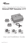
1
Technical Manuals Hard Copy Production Specifications Comb-Bound Manuals (8-1/2 x 11) Do not insert this sheet in the manual. This sheet is provided for printing and assembly instructions only. If a hard copy of this manual is required, it should be produced using the following specifications: - Input – Electronic Adobe® Acrobat PDF file - Reproduction method - Digital black and white laser copy machine - Paper media – 60 pound offset white paper - Two-sided (double-sided) copy with alternating odd/even page numbers. - Title page and last page shall be 67 pound vellum Bristol. - Binding - Bound in center with black comb binding. First and last page (covers) shall be clear, see-through plastic to allow viewing of title page and last page - First article printed shall be page-checked for correct format and legibility by ViaSat. Additional copies shall be randomly checked for correct format and legibility by the printing service provider. - Shrink-wrap entire document. SurfBeam® 2 Satellite Modem Outdoor Unit (ODU) Installation Guide ViaSat Document Number 1104460 (Rev. 001) SM2 Software Release 1.0 and higher ViaSat, Inc. 6155 El Camino Real Carlsbad, CA 92009-1699 Tel: (760) 476-2200 Fax: (760) 929-3941 www.viasat.com REGULATORY COMPLIANCE and NOTICES FCC Notice This device complies with part 15 of the FCC Rules. Operation is subjected to the following two conditions: 1. This device may not cause harmful interference, and 2. This device must accept any interference received, including interference that may cause undesired operation. NOTE: This equipment has been tested and found to comply with the limits for a Class B digital device, pursuant to Part 15 of the FCC Rules. These limits are designed to provide reasonable protection against harmful interference in a residential installation. This equipment generates, uses and can radiate radio frequency energy and, if not installed and used in accordance with the instructions, may cause harmful interference to radio communications. However, there is no guarantee that interference will not occur in a particular installation. If this equipment does cause harmful interference to radio or television reception, which can be determined by turning the equipment off and on, the user is encouraged to try to correct the interference by one or more of the following measures: -- Reorient or relocate the receiving antenna. -- Increase the separation between the equipment and receiver. -- Connect the equipment into an outlet on a circuit different from that to which the receiver is connected. -- Consult the dealer or an experienced radio/TV technician for help. Any changes or modifications not expressly approved in writing by the manufacturer could void the user’s authority to operate the equipment. CAUTION: Shielded I/O cables must be used and all covers must be in place when operating this equipment. Canadian Department of Communications compliance statement:This digital apparatus does not exceed the Class B limits for radio noise emissions from digital apparatus as set out in the Radio Interference Regulation of the Canadian Department of Communications. ROHS Compliant Notice (Restriction of Hazardous Substances) This product and its components are in compliance with Directive 2002/95/EC of the European Parliament. REACH Compliant Notice This product and its components are in compliance with EU Directive 1907/2006/EC. WEEE Notice (Waste Electrical and Electronic Equipment) ViaSat has marked this product with the WEEE symbol as a convenience to its customers for environmental responsibility per European Union Directive 2002/96/EC. This product shall be collected and disposed of in accordance with national and local laws. Waste electrical and electronic products must not be disposed of with household waste. For information on proper disposal, contact your equipment distributor or service provider. If additional information is required you may send correspondence to: [email protected] COPYRIGHT NOTICE ©Copyright 2011 ViaSat, Inc. All rights reserved under the copyright laws of the U.S. TRADEMARK NOTICE ® ® SurfBeam , the SurfBeam logo, ViaSat and the ViaSat logo are trademarks or registered trademarks of ViaSat, Inc. in the U.S. and/or other countries. Other product names included in this document are trademarks of their respective owners. DOCUMENTATION NOTICE The information, specifications, and features contained in this document are subject to change without notice and should not be construed as a commitment by ViaSat, Inc. ViaSat, Inc. assumes no responsibility for any errors that may appear in this document nor does it make an expressed or implied warranty of any kind with regard to this material, including, but not limited to, the implied warranties of merchantability and fitness for a particular purpose. ViaSat, Inc. shall not be liable for incidental or consequential damages in conjunction with, or arising out of the furnishing, performance, or use of this document or the product it describes. SurfBeam® 2 Satellite Modem Outdoor Unit (ODU) Installation Guide Revision History Revision 001 Rev. 001 Rationale Release Date Initial Release 23 Feb., 2011 1104460 Affected All pages i SurfBeam® 2 Satellite Modem Outdoor Unit (ODU) Installation Guide Warranty Information ViaSat, Inc. does not provide a warranty to the end user for this product. Any such warranty from ViaSat, including the implied warranty of merchantability or fitness for a particular purpose, is hereby disclaimed. Your service provider may provide a warranty for this product. For warranty information and repairs, please contact your service provider. Warnings, Cautions, and Notes Safety precautions or important information found in this document will normally be presented just before the point where the hazard is likely to be encountered. Symbols used to identify the information are defined as follows: Warning This symbol indicates a procedure or practice that, if not correctly followed, could result in injury, death, or long term health hazard. Caution This symbol indicates a procedure or practices that, if not correctly followed, could result in equipment damage, or destruction. This symbol indicates a procedure or practices that, if not correctly followed, could result in serious equipment damage, or destruction, or could be life threatening. This symbol indicates that a radiation source may be present and care should be taken to follow all safety advisories. This symbol indicates that a hot surface may be present and care should be taken to follow all safety advisories. Note ii This symbol indicates information that is important to observe. 1104460 Rev. 001 SurfBeam® 2 Satellite Modem Outdoor Unit (ODU) Installation Guide Important Safety Precautions and Notices Warnings. Assembling dish antennas on windy days can be dangerous. The antenna surface, even in slight winds, creates strong forces. For example, a 1.0m antenna facing a wind of 32km/h (20 mph) can undergo forces of 269 N (60 lbs). Be prepared to handle those forces safely at unexpected moments. Do not attempt to assemble, move, or mount a dish on high wind days or serious, even fatal, accidents may occur. The Vendor is not responsible or liable for damage or injury resulting from antenna installations. Antennas improperly installed or installed to an inadequate structure are very susceptive to wind damage. This damage can be very serious or even life threatening. The owner and installer assume full responsibility that the installation is structurally sound to support all loads (weight, wind and ice) and properly sealed against leaks. The Vendor is not responsible for any damage caused by an antenna due to installations that do not follow this instruction. WATCH OUT FOR WIRES! Installation of this product near power lines is dangerous. For your own safety, follow these important safety rules. 1. Perform as many functions as possible on the ground. 2. Watch out for overhead power lines. Check the distance to the power lines before starting installation. We recommend you stay a minimum of 6 meters (20 feet) from all power lines. 3. Do not install the antenna or mount assembly on a windy day. 4. If you start to drop the antenna or mount assembly, get away from it and let it fall. 5. If any part of the antenna or mount assembly comes into contact with a power line, call your local power company. DO NOT TRY TO REMOVE IT YOURSELF! They will remove it safely. 6. Properly ground the antenna assembly according to all federal and local electrically codes. Cautions. This instruction will assist you in the correct installation of the product. Read it prior to starting any installation work. Due to the nature of the method of manufacture, there may be sharp edges on metal components. Be cautious when un-packing and handling antenna parts. When this antenna is connected to a transceiver (TRIA), and powered on through interconnection to a satellite modem, a radiation source can be present. The transmitter will turn on only once a proper receive signal is obtained. Caution must be used upon completion of alignment to the satellite, and once the installation of the system has been completed. When the transmitter is operational, keep away a distance of 60 cm (2 feet). For additional information, contact your service provider. When this antenna is powered on, the transceiver (TRIA) can get hot can be present burn danger to skin. Caution must be used upon turning power on the system. Do not touch the transceiver (TRIA). Notes This product was qualified under test conditions that included the use of the supplied cable between system components. To be in compliance with regulations, the user must use this cable and install it properly. Different types of cord sets may be used for connections to the main supply circuit. Use only a main line cord that complies with all applicable product safety requirements of the country of use. Installation of this product must be in accordance with national wiring codes. ViaSat, Inc. declares that this Satellite Modem is cULus Listed and is in compliance with Canadian and U.S. safety standards and complies with the RoHS directive for hazardous materials reduction. ViaSat, Inc. declares that this Satellite Modem is in compliance with the essential requirements and other relevant provisions of Directive 1999/5/EC. Rev. 001 1104460 iii SurfBeam® 2 Satellite Modem Outdoor Unit (ODU) Installation Guide About This Manual This manual contains installation and configuration information about the SurfBeam 2 Satellite Modem Outdoor Unit (ODU). For information on installation and configuration of the SurfBeam 2 Satellite Modem Indoor Unit (IDU) refer to the SurfBeam 2 Satellite Modem Indoor Unit (IDU) Installation and Setup Guide, 1104467-001. Obtaining Additional Publications and Information Additional publications and information including user guides, white papers, application notes, release notes, SNMP MIB downloads, software updates, training schedules, and other technical information may be found on the ViaSat Customer Portal web site. The Customer Portal may be accessed through the ViaSat web site located at this URL: http://viasat.com/ Customers may apply for password access to the Customer Portal by clicking on the Customer Login link and following the link to create a new account. iv 1104460 Rev. 001 SurfBeam® 2 Satellite Modem Outdoor Unit (ODU) Installation Guide Table of Contents 1 2 3 4 5 6 ANTENNA ASSEMBLY – GENERAL INFORMATION ..........................................................................1-1 1.1 Tools and Hardware Required ......................................................................................................................1-1 ASSEMBLING A MID POLE ODU .............................................................................................................2-1 2.1 Unpacking the Antenna ................................................................................................................................2-1 2.2 Antenna Assembly .......................................................................................................................................2-1 ASSEMBLING A TOP POLE ODU .............................................................................................................3-1 3.1 Unpacking the Antenna ................................................................................................................................3-1 3.2 Antenna Assembly .......................................................................................................................................3-1 MOUNTING THE ANTENNA ON A TRI MAST ......................................................................................4-1 RECOMMENDED CABLING AND GROUNDING ..................................................................................5-1 SUMMARY OF ODU MOUNTING OPTIONS ..........................................................................................6-1 6.1 Mid-Pole Mounting Configurations .............................................................................................................6-1 6.2 Universal Mounting Configurations .............................................................................................................6-3 6.3 Top Pole Mounting Configurations ..............................................................................................................6-4 List of Figures Figure 1-1. Never Rest Dish on its Edge ...................................................................................................................1-2 Figure 1-2. Tools and Additional Materials ................................................................................................................1-4 Figure 1-3. Fasteners (1 of 3) ....................................................................................................................................1-4 Figure 1-4. Mid Pole ODU Az/El Box Components (2 of 3) ....................................................................................1-5 Figure 1-5. TRIA (3 of 3) ..........................................................................................................................................1-5 Figure 2-1. Initial Adjustments for Antenna Assembly .............................................................................................2-1 Figure 2-2. Elevation Bracket Assembly ....................................................................................................................2-3 Figure 2-3. Setting the Skew ......................................................................................................................................2-4 Figure 2-4. Assembly of Boom Arms ........................................................................................................................2-5 Figure 2-5. Assembly of TRIA Support Bracket .......................................................................................................2-6 Figure 2-6. The TRIA Assembly ...............................................................................................................................2-7 Figure 2-7. Mounting of TRIA Assembly. ................................................................................................................2-8 Figure 2-8. Attaching Ground Wire to TRIA. ............................................................................................................2-9 Figure 2-9. Attaching the Ground Wire to Boom Arm and Azimuth/Elevation Plate. .............................................2-10 Figure 2-10. Clamping ODU Assembly to Pole ......................................................................................................2-11 Figure 2-11. Tightening the Clamps. ........................................................................................................................2-12 Figure 2-12 Mounting the Boom Arms. ...................................................................................................................2-13 Figure 2-13. Initial Mounting of Receiver Dish (1) ..................................................................................................2-14 Figure 2-14. Mounting of Receiver Dish (2) ...........................................................................................................2-14 Figure 3-1. Hardware Included with Top Pole ODU. .................................................................................................3-1 Figure 3-2. Elevation Bracket Assembly. ...................................................................................................................3-3 Figure 3-3. Setting the Skew. .....................................................................................................................................3-4 Figure 3-4. Assembly of Boom Arms. ........................................................................................................................3-5 Figure 3-5. The TRIA Assembly. ...............................................................................................................................3-6 Figure 3-6. Mounting of TRIA to Support Bracket. ...................................................................................................3-7 Figure 3-7. Attaching Ground Wire to TRIA. ............................................................................................................3-8 Figure 3-8. Mounting Elevation Bracket to Pole. .......................................................................................................3-9 Figure 3-9. Mounting the Boom Arms. ....................................................................................................................3-10 Figure 3-10. Attaching the Ground Wire to Boom Arm and Elevation Bracket.......................................................3-11 Figure 3-11. Mounting the Receiver Dish. ...............................................................................................................3-12 Figure 4-1. Tri Mast Mounting Bracket.....................................................................................................................4-2 Figure 4-2. Assembling the Mount Tube to the Mount Bracket. ................................................................................4-2 Figure 4-3. Attaching the Stays to the Mount Tube....................................................................................................4-3 Rev. 001 1104460 v SurfBeam® 2 Satellite Modem Outdoor Unit (ODU) Installation Guide Figure 4-4. Wall and Roof Mounting Options. ...........................................................................................................4-4 Figure 4-5. Sliding Mounting Bracket Canister onto Pole or Mast. ...........................................................................4-5 Figure 5-1. TRIA Connections ..................................................................................................................................5-1 Figure 6-1. ODU Installed on Mid-Pole Mount..........................................................................................................6-1 Figure 6-2. ODU Mid Pole Mount with Optional Wall or Roof Mounting Hardware. ..............................................6-2 Figure 6-3. ODU Universal Mount with Optional Wall and Roof Mounting Hardware. ...........................................6-3 Figure 6-4. ODU Top Mount on Pole. ........................................................................................................................6-4 Figure 6-5. Optional Pole Mount Adaptor. .................................................................................................................6-5 List of Tables Table 1-1. Reflector Assembly Box ..........................................................................................................................1-3 Table 1-2. Inner Az/EI Box .......................................................................................................................................1-3 Table 1-3. Main Outer Box ........................................................................................................................................1-3 vi 1104460 Rev. 001 SurfBeam® 2 Satellite Modem Outdoor Unit (ODU) Installation Guide 1 ANTENNA ASSEMBLY – GENERAL INFORMATION 1.1 Tools and Hardware Required Antenna Installation will require the use of the following tools. • Ratchet driver • No 2 Pozi-drive / Philips screw driver • 13 mm (or ½”) socket • 13 mm (or 1/2”) open-ended spanner wrench • 8 mm (or 5/16th) socket • 8 mm (or 5/16”) open-ended spanner wrench Additional Materials: • Weather grade silicon sealant • Approved RG6 Cable • UV rated cable ties Package Contents: To avoid potential damage, the Eutelsat Tooway Ka antenna should remain in its protective packaging until it is required for installation. Note: Never rest the dish on its edge as shown in Figure 1-1. Rev. 001 1104460 1-1 SurfBeam® 2 Satellite Modem Outdoor Unit (ODU) Installation Guide Figure 1-1. Never Rest Dish on its Edge Suggested Installation Environment Note: Do not install antenna in a location where the line of sight to the satellite is blocked by trees or tall buildings. Attempting fine pointing during periods of dense cloud cover with precipitation may not be successful. 1-2 1104460 Rev. 001 SurfBeam® 2 Satellite Modem Outdoor Unit (ODU) Installation Guide Table 1-1 through Table 1-3 list components required for antenna assembly. Figure 1-2 through Figure 1-5 depict the hardware lists required for antenna assembly. Table 1-1. Reflector Assembly Box Number Description Qty 1 Reflector 1 2 Antenna Back Bracket 1 3 Skew Plate 1 4 Boom Arm 2 5 TRIA Mounting Bracket 1 6 M8 Spring Washer 8 7 M8 Washer 12 8 M5 Spring Washer 4 9 M8 x 20 mm Carriage Bolt 9 10 M8 Nut 8 11 M8 Serrated Nut 9 12 M8 x 20 mm Hex Head Bolt 4 13 M8 x 45 mm Carriage Bolt 4 14 M5 Pozi Pan Screw 4 Table 1-2. Inner Az/EI Box (mid pole) Number Description Qty 15 Elevation Bracket 1 16 U-shaped Pole Clamp Bolt 2 17 Pole Clamp Bar 2 18 Flange Nuts 4 19 M5 x 25mm Hex Head Bolt 1 20 M5 Tooth Lock Washer 1 21 M5 Hex Nut 1 22 Grounding Wire 1 Table 1-3. Main Outer Box Number 23 Rev. 001 Description TRIA Assembly Qty 1 1104460 1-3 SurfBeam® 2 Satellite Modem Outdoor Unit (ODU) Installation Guide Figure 1-2. Tools and Additional Materials Figure 1-3. Fasteners (1 of 3) Top Pole 1-4 1104460 Rev. 001 SurfBeam® 2 Satellite Modem Outdoor Unit (ODU) Installation Guide Figure 1-4. Mid Pole ODU Az/El Box Components (2 of 3) Figure 1-5. TRIA (3 of 3) There are two versions of ODU elevation bracket, one mounts in the middle of a support pole, the other mounts on the top of a pole or a tri mast assembly. The assembly of these two ODU versions is covered separately on the following pages. Rev. 001 1104460 1-5 SurfBeam® 2 Satellite Modem Outdoor Unit (ODU) Installation Guide 1-6 1104460 Rev. 001 SurfBeam® 2 Satellite Modem Outdoor Unit (ODU) Installation Guide 2 ASSEMBLING A MID POLE ODU The mid pole ODU has clamps that allow it to be mounted on a pole. 2.1 Unpacking the Antenna Remove the antenna dish and set it aside while still in its protective shipping material. Do not remove the dish until ready to install it. Caution Do not rest the dish on its side or lay it flat if removed from shipping material! 2.2 Antenna Assembly Complete the antenna assembly on the ground, before mounting it on the Mounting pole. This assembly has seven steps. Step 1: Adjustments for Antenna Assembly At this point the elevation setting should be pre-set as per the Work Order# to the approximate value. In order to do this, ensure the elevation lock down nuts are loosened, and then manually adjust the elevation setting to the relevant position. When the coarse elevation adjustment is complete, tighten the elevation lock down nuts. This will secure the setting while the antenna is assembled. Figure 2-1. Initial Adjustments for Antenna Assembly Rev. 001 1104460 2-1 SurfBeam® 2 Satellite Modem Outdoor Unit (ODU) Installation Guide Step 2: Fasten Antenna Back Bracket to Elevation Plate Construct the Elevation, Azimuth, and Skew Adjustment Assembly by fastening the Skew Plate to the front of the Elevation Bracket, through the Antenna Back Bracket. Ensure that you align the A arrows. Pass four M8 x 20mm Carriage Bolts through the skew plate, then the Antenna Back Bracket, and, finally, through the front of the Elevation Bracket. Secure the Skew Plate using a M8 Washer, M8 Spring Washer, and a M8 Hex Nut on each Carriage Bolt, as in (Figure 2-2). Set the skew to 90 degrees, as shown in Figure 2-3. Tighten hardware with a 13mm (or 1/2") wrench. 2-2 1104460 Rev. 001 SurfBeam® 2 Satellite Modem Outdoor Unit (ODU) Installation Guide Figure 2-2. Elevation Bracket Assembly Rev. 001 1104460 2-3 SurfBeam® 2 Satellite Modem Outdoor Unit (ODU) Installation Guide Figure 2-3. Setting the Skew 2-4 1104460 Rev. 001 SurfBeam® 2 Satellite Modem Outdoor Unit (ODU) Installation Guide Step 3: Boom Arm & TRIA Support Bracket Installation Figure 2-4. Assembly of Boom Arms Rev. 001 1104460 2-5 SurfBeam® 2 Satellite Modem Outdoor Unit (ODU) Installation Guide Position the TRIA Support Bracket onto the ends of the Boom Arms, aligning the screw holes. To fasten the TRIA Support Bracket onto the ends of the Boom Arms, insert one M8 x 45mm Carriage Bolt into each of the four square-holes in the TRIA Support Bracket, making sure that the square shoulders on the bolt are seated in the square hole. Install one M8 Washer, One M8 Spring Washer and one M8 Nut onto each M8 Bolt and tighten with a 13mm (or 1/2") wrench (Figure 2-5). Figure 2-5. Assembly of TRIA Support Bracket Step 4: TRIA Installation Start by removing the TRIA and the mounting hardware kit from its box (Figure 2-6). Position the TRIA onto the four mounting posts on the TRIA mounting bracket (Figure 2-7). Note: The TRIA is positioned on the incorrect side if the TRIA cooling fins come into contact with the TRIA Mounting Bracket. 2-6 1104460 Rev. 001 SurfBeam® 2 Satellite Modem Outdoor Unit (ODU) Installation Guide Figure 2-6. The TRIA Assembly Insert the four M5 Pozi-Pan Screws and M5 Spring Washers (included with the TRIA, not the ODU fasteners) into the TRIA mounting holes and thread into the TRIA Mounting Bracket (Figure 2-7). Tighten each screw using a number 2 Pozi-drive or Phillips screw driver. Rev. 001 1104460 2-7 SurfBeam® 2 Satellite Modem Outdoor Unit (ODU) Installation Guide Figure 2-7. Mounting of TRIA Assembly. 2-8 1104460 Rev. 001 SurfBeam® 2 Satellite Modem Outdoor Unit (ODU) Installation Guide Now run the ground wire from the TRIA connection marked GND to the ground lug (Figure 2-8) on the Elevation Plate (Figure 2-9) along the boom arm. Wrap the ground wire and boom arm with UV resistant cable ties, as shown in Figure 2-9. Figure 2-8. Attaching Ground Wire to TRIA. Rev. 001 1104460 2-9 SurfBeam® 2 Satellite Modem Outdoor Unit (ODU) Installation Guide Figure 2-9. Attaching the Ground Wire to Boom Arm and Azimuth/Elevation Plate. Step 5: Pole Clamp Hardware Installation Position each M8 U-Bolt through the Elevation Assembly as shown in Figure 2-10. Position the closed-hole end of the Pole Clamps onto the M8 U-Bolts, allowing the open-slot end of the Pole Clamps to hang loose. Install the four M8 Serrated Nuts onto the M8 U-Bolts, threading the Nuts only until the U-Bolt threads protrude through the nut. 2-10 1104460 Rev. 001 SurfBeam® 2 Satellite Modem Outdoor Unit (ODU) Installation Guide Figure 2-10. Clamping ODU Assembly to Pole Rev. 001 1104460 2-11 SurfBeam® 2 Satellite Modem Outdoor Unit (ODU) Installation Guide Step 6: Install Antenna onto Suitable Pole With the antenna dish not yet installed, position the Antenna onto a suitable Pole as shown in Figure 2-10. Rotate each Pole Clamp to engage the slotted end of the Clamp with the other side of the U-Bolt as shown in Figure 2-10. Hand-tighten each of the four M8 Serrated Nuts to bring the two Pole Clamps into contact with the Pole (as shown in Figure 2-11), then tighten the four nuts with a 13mm (or 1/2") wrench. Figure 2-11. Tightening the Clamps. Step 7: Attaching the Boom Arms Slide the Boom Arms into the slots at the bottom of the Antenna Back Bracket, aligning the screw holes. To fasten the Boom arm to the Antenna Back Bracket, insert one M8 x 20mm Hex Head Bolt through one M8 Washer and into each of the four screw holes in the slot and tighten with a 13mm (or 1/2") wrench (Figure 2-4). 2-12 1104460 Rev. 001 SurfBeam® 2 Satellite Modem Outdoor Unit (ODU) Installation Guide Figure 2-12 Mounting the Boom Arms. Step 8: Elliptical Dish Installation Fasten the Elliptical Dish to Antenna Back Bracket using five M8 x 20mm Carriage Bolts inserted through the front of the Dish and through the five tabs located on the rim of the Antenna Back Bracket. First, support the dish using a M8 x 20mm carriage bolt that has been fastened in the upper hole of the dish (Figure Figure 2-13). Let the slot in the antenna back bracket support the weight of the dish. Then insert the rest of the carriage bolts and secure them with serrated nuts. Make sure that the square shoulders on the carriage bolts are seated in the square holes in the Dish. Secure the Dish to the Antenna Back Bracket using a M8 Serrated Flange Nut on each carriage bolt and tighten with a 13mm (or 1/2") wrench (Figure 2-14). Note: Depending on installation situation, receiver dish might be attached prior to clamping to pole, or afterwards. Rev. 001 1104460 2-13 SurfBeam® 2 Satellite Modem Outdoor Unit (ODU) Installation Guide Figure 2-13. Initial Mounting of Receiver Dish (1) Figure 2-14. Mounting of Receiver Dish (2) 2-14 1104460 Rev. 001 SurfBeam® 2 Satellite Modem Outdoor Unit (ODU) Installation Guide 3 ASSEMBLING A TOP POLE ODU The top pole ODU has an elevation bracket that allows it to be mounted on the top of a pole or a tri mast assembly. Figure 3-1 shows the hardware included with a top pole ODU assembly. 3.1 Unpacking the Antenna Remove the antenna dish and set it aside while still in its protective shipping material. Do not remove the dish until ready to install it. Caution Do not rest the dish on its side or lay it flat if removed from shipping material! 3.2 Antenna Assembly Complete the antenna assembly on the ground, before mounting it on the Mounting pole. This assembly has seven steps. Step 1: Adjustments for Antenna Assembly At this point the elevation setting should be pre-set as per the Work Order# to the approximate value. In order to do this, ensure the elevation lock down nuts are loosened, and then manually adjust the elevation setting to the relevant position. When the coarse elevation adjustment is complete, tighten the elevation lock down nuts. This will secure the setting while the antenna is assembled. Figure 3-1. Hardware Included with Top Pole ODU. Rev. 001 1104460 3-1 SurfBeam® 2 Satellite Modem Outdoor Unit (ODU) Installation Guide Step 2: Fasten Antenna Back Bracket to Elevation Plate Construct the Elevation, Azimuth, and Skew Adjustment Assembly by fastening the Skew Plate to the front of the Elevation Bracket, through the Antenna Back Bracket. Ensure that you align the A arrows. Pass four M8 x 20mm Carriage Bolts through the skew plate, then the Antenna Back Bracket, and, finally, through the front of the Elevation Bracket. Secure the Skew Plate using a M8 Washer, M8 Spring Washer, and a M8 Hex Nut on each Carriage Bolt, as in Figure 3-2. Set the skew to 90 degrees, as shown in Figure 3-3. Tighten hardware with a 13mm (or 1/2") wrench. 3-2 1104460 Rev. 001 SurfBeam® 2 Satellite Modem Outdoor Unit (ODU) Installation Guide Figure 3-2. Elevation Bracket Assembly. Rev. 001 1104460 3-3 SurfBeam® 2 Satellite Modem Outdoor Unit (ODU) Installation Guide Figure 3-3. Setting the Skew. Step 3: Boom Arm & TRIA Support Bracket Installation Assemble the boom arms and TRIA support bracket as shown in Figure 3-4. 3-4 1104460 Rev. 001 SurfBeam® 2 Satellite Modem Outdoor Unit (ODU) Installation Guide Figure 3-4. Assembly of Boom Arms. Rev. 001 1104460 3-5 SurfBeam® 2 Satellite Modem Outdoor Unit (ODU) Installation Guide Figure 3-5. The TRIA Assembly. Step 4: TRIA Installation Start by removing the TRIA and the mounting hardware kit from its box. The TRIA assembly is shown in Figure 3-5. Position the TRIA onto the four mounting posts on the TRIA mounting bracket (Figure 3-6). Note: The TRIA is positioned on the incorrect side if the TRIA cooling fins come into contact with the TRIA Mounting Bracket. Insert the four M5 Pozi-Pan Screws and M5 Spring Washers (included with the TRIA, not the ODU fasteners) into the TRIA mounting holes and thread into the TRIA Mounting Bracket (Figure XX). Tighten each screw using a number 2 Pozi-drive or Phillips screw driver. 3-6 1104460 Rev. 001 SurfBeam® 2 Satellite Modem Outdoor Unit (ODU) Installation Guide Figure 3-6. Mounting of TRIA to Support Bracket. Rev. 001 1104460 3-7 SurfBeam® 2 Satellite Modem Outdoor Unit (ODU) Installation Guide Now run the ground wire from the TRIA connection marked GND to the ground lug (Figure 3-7) on the Elevation Plate (Figure XX) along the boom arm. Wrap the ground wire and boom arm with UV resistant cable ties. Figure 3-7. Attaching Ground Wire to TRIA. 3-8 1104460 Rev. 001 SurfBeam® 2 Satellite Modem Outdoor Unit (ODU) Installation Guide Step 5: Pole Clamp Hardware Installation The ODU sits on top of a pole (or tri mast). Loosen the six bolts on the clamping bracket until the bracket just fits onto the pole. Tighten until the bracket is firm, but loose enough that the ODU assembly can still be turned to accomplish the initial pointing to the satellite (Figure 3-8). Use the compass heading provided on the work order. Once fine pointing is finished, carefully tighten the nuts until the bracket is seated firmly on the pole so that the bracket will not move if a strong wind hits the antenna dish. Figure 3-8. Mounting Elevation Bracket to Pole. Rev. 001 1104460 3-9 SurfBeam® 2 Satellite Modem Outdoor Unit (ODU) Installation Guide Step 7: Attaching the Boom Arms Slide the Boom Arms into the slots at the bottom of the Antenna Back Bracket, aligning the screw holes. To fasten the Boom arm to the Antenna Back Bracket, insert one M8 x 20mm Hex Head Bolt through one M8 Washer and into each of the four screw holes in the slot and tighten with a 13mm (or 1/2") wrench (Figure 3-9). Figure 3-9. Mounting the Boom Arms. 3-10 1104460 Rev. 001 SurfBeam® 2 Satellite Modem Outdoor Unit (ODU) Installation Guide Figure 3-10. Attaching the Ground Wire to Boom Arm and Elevation Bracket. Now attach the TRIA ground wire and the earth ground wire to the elevation bracket lug, as shown in Figure 3-10. Use cable ties to secure the earth ground wire to the pole. Step 8: Elliptical Dish Installation Fasten the Elliptical Dish to Antenna Back Bracket using five M8 x 20mm Carriage Bolts inserted through the front of the Dish and through the five tabs located on the rim of the Antenna Back Bracket. First, support the dish using a M8 x 20mm carriage bolt that has been fastened in the upper hole of the dish (Figure 3-11). Let the slot in the antenna back bracket support the weight of the dish. Then insert the rest of the carriage bolts and secure them with serrated nuts. Make sure that the square shoulders on the carriage bolts are seated in the square holes in the Dish. Secure the Dish to the Antenna Back Bracket using a M8 Serrated Flange Nut on each carriage bolt and tighten with a 13mm (or 1/2") wrench. Rev. 001 1104460 3-11 SurfBeam® 2 Satellite Modem Outdoor Unit (ODU) Installation Guide Note: Depending on installation situation, the receiver dish might be attached prior to mounting on pole. Figure 3-11. Mounting the Receiver Dish. 3-12 1104460 Rev. 001 SurfBeam® 2 Satellite Modem Outdoor Unit (ODU) Installation Guide 4 MOUNTING THE ANTENNA ON A TRI MAST After the assembly is complete, use the following steps to mount the antenna to the predetermined location. The mount must be attached to a structural member, i.e. solid wall or wall studding. Caution Do not attempt to mount the tri mast on slate, Spanish tile, or shake shingle roof materials. When mounting on a brick wall or chimney, drill the mounting hole into brick, not the mortar joints. Do not install over a living area, the preferred location is over the eves of a roof. Wall Mount Example Step 1: Locate the wall stud in the area of installation. Align the holes of the Mounting Bracket with the structural member. Mark the upper hole in the center of the bracket with a pencil and drill a 3.175 mm (1/8”) hole. Attach the Mounting Bracket to the wall with a 6.35 mm x 76.2 mm (1/4” X 3”) lag screw and washer, but do not tighten. Use a Spirit Level to ensure that the bracket is horizontally and vertically level. Drill a 3.175 mm (1/8”) hole for the bottom hole in the center of the bracket and insert a 6.35 mm x 76.2 mm (1/4” X 3”) lag screw and washer. Tighten both lag screws. Drill a 3.175 mm (1/8”) hole in each of the holes in the Mounting Bracket base. Insert and tighten a 7.94 mm x 38.1 mm (5/16” X 1 1/2”) lag screw and washer in each corner hole (Figure 4-1). Note: Fill all holes with weather-grade silicon sealer before inserting bolts or screws. Note: The lag screws and washers are not included in the Tri Mast package. Rev. 001 1104460 4-1 SurfBeam® 2 Satellite Modem Outdoor Unit (ODU) Installation Guide Figure 4-1. Tri Mast Mounting Bracket. Step 2: To attach the Mount Tube to the Mount Bracket, align the bottom hole at the base of the Mount Tube to the arched slot at the bottom of the Mount Bracket right side flange. Insert a 7.94 mm x 19.05 mm (5/16” X 3/4") UNC Carriage Bolt through the right flange and wall of the Mount Tube. Secure the Carriage Bolt using a 7.94 mm (5/16”) UNC Serrated Flange Nut inside the Mount Tube. Repeat this procedure to attach the Mount Bracket left flange to the bottom hole at the base of the Mount Tube. Next, swing the Mount Tube up to align the top hole at the base of the Mount Tube with the center hole in the side flange of the Mount Bracket. Pass a 7.94 mm x 63.5 mm (5/16” X 2 1/2") UNC Hex Head Tap Bolt through the hole in the right side flange, the Mount Tube, and the left side flange and secure using a 7.94 mm (5/16”) UNC Serrated Flange Nut (Figure 4-2). Figure 4-2. Assembling the Mount Tube to the Mount Bracket. Step 3: Remove the Adjustable Tri Mast Stays from the package and loosen all of the 7.94 mm (5/16”) UNC joint hardware. Caution edges may be sharp; gloves are recommended. Position the Tube Collar just below the bend in the Mount Tube (Figure 4-3). Attach the adjustable stays to the collar as demonstrated in (Figure 4-3). The adjustable Stays should be assembled so that the notch is visible on the left hand side of the assembly. Place an adjustable Stay on each side of the Tube Collar flanges and align the holes. 4-2 1104460 Rev. 001 SurfBeam® 2 Satellite Modem Outdoor Unit (ODU) Installation Guide Pass a 7.94 mm x 38.1 mm (5/16” x 1.5”) UNC Carriage Bolt through the hole on the adjustable Stay on the right, both Tube Collar flange holes, and the hole in the adjustable Stay on the left. Secure with a 7.94 mm (5/16”) UNC Serrated Flange Nut, as in (Figure 4-3) and tighten using a 12.7 mm (½”) socket wrench. Note: The lag screws and washers are not included ODU in the package. Figure 4-3. Attaching the Stays to the Mount Tube. Use a Spirit Level to verify the horizontal and vertical level of the Mount Tube above the vertical bend. Mark the holes at the bottom of the Stays and drill a 1/8” for each. Use a 7.94 mm x 38.1 mm (5/16” x 1 1/2”) lag screw and washer to attach each Stay to the wall. Do this procedure for both horizontal and vertical mounts. Position the adjustable Stays at an angle of 60º - 65º from the tube as shown in (Figure 4-4) and attach each Tri Mast Mount Plate to the building support structure using two fasteners per plate (Fasteners not supplied). Fasteners must be attached to a structural member. Tighten all the 7.94 mm (5/16”) UNC joints. Rev. 001 1104460 4-3 SurfBeam® 2 Satellite Modem Outdoor Unit (ODU) Installation Guide Attention: For vertical wall mounts, fill all holes with weather-grade silicon sealer before inserting bolts or screws. For sloped roof mounts, fill all holes with the appropriate asphaltbased, synthetic-rubber, or acrylic co-polymer roof sealant (Figure 4-4). Figure 4-4. Wall and Roof Mounting Options. Step 4: Taking heed of the safety instructions mentioned at the start of this instruction manual, carry the Antenna assembly to the Mount Tube location. Loose the 6 nuts on the flange of the mounting bracket and slide it onto the top of the Mount Tube (Figure 4-5). Secure in place, then hand-tighten the Flange Nuts. 4-4 1104460 Rev. 001 SurfBeam® 2 Satellite Modem Outdoor Unit (ODU) Installation Guide Figure 4-5. Sliding Mounting Bracket Canister onto Pole or Mast. Rev. 001 1104460 4-5 SurfBeam® 2 Satellite Modem Outdoor Unit (ODU) Installation Guide 4-6 1104460 Rev. 001 SurfBeam® 2 Satellite Modem Outdoor Unit (ODU) Installation Guide 5 RECOMMENDED CABLING AND GROUNDING Connect the Transmit COAX RG6 Cable to the left connector on the TRIA, labeled “TX”. Connect the Receive COAX RG6 Cable to the right connector on the TRIA, labeled “RX” (Figure 5-1). Figure 5-1. TRIA Connections After attaching the COAX RG6 Cabling to the TRIA RX and TX connectors, using cable-ties, attach the TX and RX Cables together every 18 inches to the boom arm. Next attach the cables to the Mount Tube right below the vertical bend with a large cable-tie. Run the cables down the Mount Tube to the Mount Bracket maintaining a straight line and attaching them to the Bracket every 18-24 inches with large cable-ties. The National Electric Code (NEC) and local code require grounding the Antenna. Grounding also protects system components against static voltage build up and electrical surges. Attach a #10 copper wire to the ground lug on the TRIA and ground the other end to the Antenna structure. An approved 2.2 6Hz dual grounding block is also required. Note: The ODU package does not provide the grounding block. For information on installation and configuration of the SurfBeam 2 Satellite Modem Indoor Unit (IDU) refer to the SurfBeam 2 Satellite Modem Indoor Unit (IDU) Installation and Setup Guide, 1104467-001. Rev. 001 1104460 5-1 SurfBeam® 2 Satellite Modem Outdoor Unit (ODU) Installation Guide 5-2 1104460 Rev. 001 SurfBeam® 2 Satellite Modem Outdoor Unit (ODU) Installation Guide 6 SUMMARY OF ODU MOUNTING OPTIONS 6.1 Mid-Pole Mounting Configurations The ODU can be installed using a mid-pole mount (Figure 6-1) or a pole mount with optional wall or roof mounting hardware (Figure 6-2). The mid-pole configuration is designed to mount to a pre-existing pole. The universal mounting kit remains packaged separately as an optional mounting kit. Figure 6-1. ODU Installed on Mid-Pole Mount. The top-pole mounting (Figure 6-4) is intended to mount on a pole that is either cemented into the ground or mounted to the wall or roof of a building. The reflector, boom arms, TRIA, antenna back bracket and skew plate are identical for both ODU configurations. The Azimuth/Elevation Head configuration and mounting brackets are different for the two configurations. Rev. 001 1104460 6-1 SurfBeam® 2 Satellite Modem Outdoor Unit (ODU) Installation Guide Figure 6-2. ODU Mid Pole Mount with Optional Wall or Roof Mounting Hardware. 6-2 1104460 Rev. 001 SurfBeam® 2 Satellite Modem Outdoor Unit (ODU) Installation Guide 6.2 Universal Mounting Configurations The ODU can be installed using a universal mount suitable for wall or roof locations (Figure 6-3), or installed using a universal top mount on a pole (Figure 6-4). Figure 6-3. ODU Universal Mount with Optional Wall and Roof Mounting Hardware. Rev. 001 1104460 6-3 SurfBeam® 2 Satellite Modem Outdoor Unit (ODU) Installation Guide 6.3 Top Pole Mounting Configurations The ODU can also be installed as a top mount on a pole configuration. Note: The mounting pole must be securely fixed so that it does not move; if secured in the ground, use at least 120 lbs (55 kg) of concrete to stabilize the pole. Figure 6-4. ODU Top Mount on Pole. An optional pole mount adapter is available for mounting the system to a galvanized schedule 40 2-3/8” O.D. pole (Figure 6-5). 6-4 1104460 Rev. 001 SurfBeam® 2 Satellite Modem Outdoor Unit (ODU) Installation Guide Figure 6-5. Optional Pole Mount Adaptor. Rev. 001 1104460 6-5 SurfBeam® 2 Satellite Modem Outdoor Unit (ODU) Installation Guide 6-6 1104460 Rev. 001