1
XR150/XR350/XR550
USER’S GUIDE
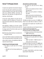
Silencing an Alarm
When the alarm bell or siren is sounding, enter your user code or
present your card to a keypad or reader during the Status List display.
All/Perimeter, Home/Sleep/Away, or Home/Sleep/Away with Guest System
IS THIS A FALSE ALARM? or CANCEL VERIFY displays.
• If a burglar alarm is valid, press NO or VERIFY to send a
verification message to the Central Station.
• If a valid alarm has not occurred, press YES or CANCEL to cancel
the alarm and send an Abort or Cancel message to the Central
Station and the security system will be disarmed.
© 2013 Digital Monitoring Products, Inc.
Information furnished by DMP is believed to be accurate and reliable.
This information is subject to change without notice.
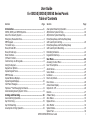
User Guide
for XR150/XR350/XR550 Series Panels
Table of Contents
SectionPage
Introduction........................................................................ 1
XR150, XR350, and XR550 Systems.............................................1
About Your Security System........................................................1
Emergency Evacuation Plans.......................................................2
DMP Keypads ............................................................................3
The Select keys..........................................................................4
Power/Armed LED......................................................................4
Power/Armed Logo.....................................................................5
Panic Functions..........................................................................5
7/0 Panic Function......................................................................6
Common Keys on All Keypads.....................................................6
Using the Keypad.......................................................................6
Keypad User Options..................................................................7
Special Keypad Tones.................................................................8
DMP Wireless ............................................................................9
Special Wireless Displays............................................................9
Special Keypad Displays............................................................ 10
Cell Phone Messages................................................................ 11
MyAccess™ Text Messaging Commands...................................... 11
Understanding Security System Terms....................................... 11
Arming and Disarming ...................................................... 14
General Arming Operation......................................................... 14
Key Fob Arming........................................................................15
Key Fob Disarming................................................................... 16
Area System Arming Operation.................................................. 16
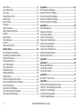
SectionPage
Area System Disarming Operation............................................. 17
All/Perimeter System Arming..................................................... 18
All/Perimeter System Disarming................................................. 19
Home/Sleep/Away and Home/Sleep/Away
with Guest System Arming........................................................ 20
Home/Sleep/Away and Home/Sleep/Away
with Guest System Disarming.................................................... 21
Extending Schedules ............................................................... 22
Keypad Shortcut Keys............................................................... 22
User Menu......................................................................... 23
Accessing the User Menu ......................................................... 23
User Menu Options................................................................... 23
Alarm Silence...........................................................................25
Sensor Reset............................................................................25
Lockdown................................................................................25
Door Lock/Unlock..................................................................... 26
Door Access.............................................................................26
Armed Areas Display ............................................................... 26
Outputs On Off....................................................................... 26
Favorite...................................................................................27
Z-Wave Setup..........................................................................28
Zone Status ............................................................................33
Bypass Zones ..........................................................................34
Zone Monitor...........................................................................34
System Status..........................................................................35
System Test.............................................................................36
XR150/XR350/XR550 User Guide
i
User Profiles............................................................................37
User Profiles Chart...................................................................41
User Codes .............................................................................42
Forgive Failure to Exit............................................................... 44
Ambush Code .........................................................................45
Extend Closing.........................................................................45
Schedules................................................................................45
Setting Schedules..................................................................... 46
Setting Holiday Dates (HOL)..................................................... 48
Favorites..................................................................................48
Display Events.........................................................................49
Service Request.......................................................................49
Fire Drill..................................................................................50
System Setup Record .............................................................. 51
System Setup.................................................................... 51
Key Fob Button Programming.................................................... 52
Area Names and Numbers Record............................................. 53
Z-Wave Device Name................................................................ 54
Z-Wave Favorites List................................................................ 55
User Profiles Record ................................................................ 56
User Codes Record ..................................................................57
Schedules Record.....................................................................58
Holiday Date Record................................................................. 59
Output Record.........................................................................59
About the Display Events Section.............................................. 60
Arming and Disarming Event Displays........................................ 61
Zone Event Displays................................................................. 61
Supervisory Event Displays....................................................... 61
User Code Change Event Displays............................................. 61
Zone Bypass Event Displays...................................................... 61
ii
Appendix A........................................................................ 61
Door Access Event Displays....................................................... 62
System Monitor Event Displays.................................................. 63
Schedule Change Event Displays............................................... 63
Wireless Jamming Event Displays.............................................. 64
Wireless Trouble Event Displays................................................. 64
Appendix B........................................................................ 65
Zone Status Browser ............................................................... 65
Bypass Zones Browser.............................................................. 65
Zone Monitor Browser.............................................................. 66
Add User Codes Browser........................................................... 66
Change User Codes Browser..................................................... 67
Delete User Codes Browser....................................................... 67
Add User Profiles Browser......................................................... 68
Change User Profiles Browser.................................................... 68
Delete User Profiles Browser..................................................... 69
Output Groups Browser............................................................ 69
Appendix C........................................................................ 69
Appendix D........................................................................ 70
Outputs On/Off Browser........................................................... 70
User Disarm and Entry.............................................................. 70
Entering User Names ............................................................... 71
Appendix E......................................................................... 71
Easy Entry™ User’s Guide......................................................... 73
Appendix F......................................................................... 74
Email/Cell Phone Message User’s Guide..................................... 74
MyAccess™ Text Messaging Commands...................................... 76
Subscribe to Text Messages...................................................... 79
Frequently Asked Questions...................................................... 80
Common Keypad Displays......................................................... 81
XR150/XR350/XR550 User’s Guide
XR150, XR350, and XR550 Systems
Introduction
A Note About False Alarms
This Guide covers operation of the XR150, XR350, and XR550 Series
systems.
About Your Security System
The system has been designed with your safety and comfort in
mind. It uses the latest in computer based technology to create
the most advanced, user friendly security, fire, and access control
system available.
The system combines ease of use with a simple to understand DMP
keypad to offer the full range of features requested by today’s
security system owners.
Use the system to turn portions of your protection on or off by
pressing a few keys, or have the system turn on or off automatically
by entering a simple schedule. You can add, delete, and change
personal user codes at any time or check the status of protection
devices in the system.
Parts of the System
There are two main parts to the security system, the keypad and
the keypad User Menu.
LCD Keypad
This is the device we have placed at certain locations throughout
the premises that allow you to turn the system protection on and
off using your personal user code.
Keypad User Menu
The keypad provides a simple User Menu containing all of the
functions you need to fully operate your system such as changing
the time of day or a personal user code.
Introduction
One of the most important concerns facing the security industry
today is false alarms. The accidental dispatching of police and
fire agencies places others in jeopardy by limiting the response
capability of those emergency service units.
As part of our commitment to reducing false alarms, we would like
to encourage you to read this guide thoroughly. All the information
contained here can help you quickly, and comfortably, learn the
system operation. If you have any additional questions, or feel
that you need more training, please do not hesitate to contact
your alarm dealer.
Note: There may be a 30-second alarm communication delay
pre‑programmed at installation to allow disarming if a false alarm
occurs. This delay is optional and can be removed or increased to
45 seconds by your alarm dealer.
Test Your System Weekly
It is recommended that you test the burglary portion of your
system at least once each week. Testing should involve an active
test of all doors, windows, and motion detectors connected to your
system. If your system also has fire protection, call the service
department to find out how this portion of your system should be
tested.
Refer to the System Test section of this guide for instructions on
testing the burglary portion of your system and refer to the Fire
Drill section for instructions on testing your system fire bells.
XR150/XR350/XR550 User Guide
1
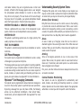
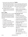
Emergency Evacuation Plans
Early Detection
The National Fire Protection Association recommends that you
establish an emergency evacuation plan to safeguard lives in the
event of a fire or other emergency.
Draw a Floor Plan of Your Home or Business
On a clean sheet of paper, draw the walls, windows, doors, and
stairs. Also draw any obstacles that a person may encounter while
exiting the building such as large furniture or appliances.
The best way to survive a fire or other emergency is to get out
early. The installation of a fire alarm system, with smoke and
carbon monoxide detectors in each room, can greatly decrease
your risk of loss or injury.
First Floor
Second Floor
Develop Escape Routes
Fire Escape
Determine at least two routes the occupants in each room can
take to safely escape. One route can be the most obvious such
as the door. Another can be through a window that can be easily
opened. If the window is high off the ground, an escape ladder
should be provided.
Draw arrows on the floor plan to show escape routes from each
room.
Window Ladder
Building Front
Building Back
Decide Where to Meet
Prearrange a meeting place outside and away from where
emergency personnel are likely to be working. A neighbor’s house
or across the street in front of the house are good locations. Always
perform a head count to make sure all occupants safely exited.
NEVER ENTER A BURNING BUILDING. If the head count shows one
or more persons missing, give this information immediately to the
authorities. Never enter a building to look for someone.
Practice Your Escape Plans
Devising an escape plan is only the beginning. For the plan to be
effective everyone should practice escape routes from each room.
2
XR150/XR350/XR550 User Guide
Introduction
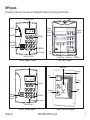
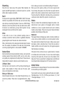
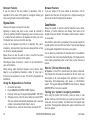
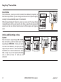
DMP Keypads
Your system may have one or more easy to use LCD keypads that allow you to properly operate the system.
AC Power/Armed LED
32-Character Display
Power LED
ABC PRINTING
F R I 2 : 51 AM
Armed LED
Backlit Logo
and Proximity
Antenna
Select Keys
1
2
3
4
5
6
7
8
9
0
CMD
32-Character
Display with
Four Touch
Select Areas
Data Entry
Digit Keys
ABC PRINTING
F R I 2 : 51 AM
COMMAND Key
Back Arrow Key
Data Entry Digit keys
Logo
Icon
Three Panic Icons
Thinline™/Aqualite™ Keypad
Back Arrow Key
COMMAND Key
Clear Touch™ Keypad
32-Character Display
Interactive Shield
Proximity Card
Reader
Dealer
Logo
SMITH RESIDENCE
FRI
12:51 PM
MON 5:35 AM
Panic
Select Keys
CURRENT
Chime
HI LO
Check-In
82
TODAY
Local Weather
Conditions
Backlit Logo
and Proximity
Antenna
COMMAND Key
98 77
HI
80
DISARMED
Reset
Micro SD
Card Slot
Carousel
Menu
LO
WEDNESDAY 74
Back Arrow Key
Data Entry Digit keys
Thinline™ Wireless Keypad
Introduction
Graphic Touchscreen Keypad
XR150/XR350/XR550 User Guide
3
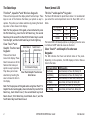
The Select keys
Power/Armed LED
Thinline™, Aqualite™ and Wireless Keypads:
Thinline™ and Aqualite™ Keypads:
There are four keys under the display called the Select keys. These
keys are one of the features that make your system so easy to
operate. They allow you to make selections by pressing the Select
key under a choice shown in the display.
Note: For the purposes of this guide, when instructed to press
the first Select key, press the far left Select key; the second
Select key is the second from the left; third Select key is second
from the right; and the fourth Select key is the far right key.
Clear Touch™ and
Select Area 2
Graphic Touchscreen
Select
Area 1
Keypads:
There are four Select
Areas in the display. These
Select Areas are one of the
features that make your
system so easy to operate.
They allow you to make
selections by touching the
area to choose the item in
the display.
Select Area 3
Select Area 4
LED Operation
ON (Steady)
OFF
BLINKS
AC
OK
Trouble
OK
Battery
OK
N/A
Trouble
The Armed LED is ON steady anytime any burglary protection area
is armed and is OFF when ALL areas are disarmed.
Clear Touch™ and Graphic Touchsreen
Keypads:
The LED indicates the Power and Armed status of the panel.
Depending on the operation, the LED displays in Red or Blue as
listed in the table.
32-Character Display
Clear Touch/Graphic Touchscreen
Select Areas
Note: For the purposes of this guide when using Clear Touch™ or
Graphic Touchscreen Keypads, when instructed to press the first
Select key, touch Select Area 1; the second Select key touch
Select Area 2; third Select key touch Select Area 3; and the
fourth Select key touch Select Area 4.
4
The Power LED indicates the panel Power status. It is recommended
you contact the service department when the Power LED is off or
blinks.
Color and Activity
Blue Steady
Blue Blinking
No Light
Red Steady
Red/Blue Alternate
Red Blinking
XR150/XR350/XR550 User Guide
LED Operation
Panel Disarmed, AC Power OK, Battery OK
Panel Disarmed, AC Power OK, Battery Fault
Panel Disarmed, AC Power Fault, Battery OK
Panel Armed, AC Power OK, Battery OK
Panel Armed, AC Power OK, Battery Fault
Panel Armed, AC Power Fault, Battery OK
Introduction
Power/Armed Logo
Panic Functions
The backlit logo on the keypad indicates the panel armed status
and the keypad power status. Depending on the operation, the
logo displays Red or Green as listed in the table.
Your keypad may be set up to send a Panic, Emergency, or Fire
report to the central station. This function is optional. If this
option is programmed for your keypad, icons display below the top
row Select keys/areas.
Thinline™ Wireless Keypads:
Color and Activity
Green Steady
Green Blinking
No Light
Red Steady
Red/Green Alternate
Red Blinking
Armed Status
Panel Disarmed
Panel Disarmed
Panel Disarmed
Panel Armed
Panel Armed
Panel Armed
Keypad Power Status
AC Power OK, Battery OK
AC Power OK, Battery Fault
AC Power Fault, Battery OK
AC Power OK, Battery OK
AC Power OK, Battery Fault
AC Power Fault, Battery OK
Thinline™, Aqualite™ and Wireless Keypads:
Press and hold the two Select keys adjacent to the desired icon for
2 seconds, until a beep from the keypad is heard.
Top Row Select Keys
Police
Emergency
Fire
Thinline™/Aqualite™/Thinline™ Icon Keypad Panic Keys
With Shaded Buttons To Indicate Police Panic Keys
Clear Touch™ and Graphic Touchscreen Keypads:
Touch the icon for 2 seconds until a beep is heard.
PRESS AND HOLD BUTTON TO SEND
PANIC OPTIONS
Touch Select Areas
POLICE
Police
Emergency
EMERGENCY
FIRE
Fire
Clear Touch™ Keypad Panic Icons Graphic Touchscreen Panic Icons
Introduction
XR150/XR350/XR550 User Guide
5
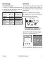
7/0 Panic Function
Using the Keypad
Thinline™ and Aqualite™ Keypads may also be programmed at
installation to allow the user to initiate an optional Panic alarm by
simultaneously pressing and holding the 7 and 0 (zero) keys. When
the 7 and 0 keys are pressed for a short time, the keypad sends a
Panic alarm report to the central station.
Your system may be programmed to display the User Menu and
Status Display text in multiple languages. When the COMMAND
key is pressed, the option to choose the language displays. Select
the language you want to use. The language chosen continues to
display at this keypad until another language is chosen.
Note: The 7/0 Panic Function is not available on Clear Touch™,
Thinline™ Icon, Wireless, or Graphic Touchscreen keypads.
Keypad Displays Current Programming
Multi-lingual Display Option
Thinline™ and Aqualite™ Keypads:
Common Keys on All Keypads
Data Entry Digit keys
These keys allow you to enter your user code when arming or
disarming or enter other information into the system.
COMMAND (CMD) key
The COMMAND key allows you to advance through the keypad
displays, User Menu, or complete a data entry function.
Back Arrow (<—) key
The Back Arrow (<—) key is used to go back through the keypad
displays while operating your system. You can press the Back Arrow
key to back up through the list of functions in the User Menu or to
erase the last character you entered.
Most User Menu options displayed at the keypad show the currently
selected option in the panel memory. These options are either
shown as a number, a blank, or a NO or YES. To change a number
press any top row Select key. The current option is replaced with a
dash. Press the number(s) on the keypad you want to enter as the
new number for that option.
It is not necessary to enter numbers with leading zeros. The panel
automatically right justifies when you press the COMMAND key. To
change an option that requires a NO or YES response, press the top
row Select key for the response not selected. For example, if the
current option is YES and you want to change it to NO, press the
third Select key. The display changes to NO. Press the COMMAND
key to go to the next option.
Multiple Displays (XR350 and XR550 System
Only)
For some User Menu options, such as Access Areas under User
Profiles there are several displays containing lists. For example,
when using Access Areas, areas 1 through 32 display on four
separate displays. First, areas 1 through 8 display. Press the
COMMAND key to display areas 9 through 16. Press the COMMAND
key again to display areas 17 through 25. Press the COMMAND key
one more time to display areas 26 through 32.
6
XR150/XR350/XR550 User Guide
Introduction
Note: Only areas pre-programmed at installation can be viewed.
Keypad User Options
Asterisks in Area Armed Displays
The User Options allow you to make adjustments to your keypad to
best fit your environment and needs.
Thinline™, Aqualite™ and Wireless keypads: Press and hold the
Back Arrow and COMMAND keys for two seconds. The keypad
display changes to SET BRIGHTNESS. Press the COMMAND key to
display the next option or the Back Arrow key to exit.
Clear Touch™ keypads: Touch and hold the center of the logo icon
for two seconds. The display changes to SET BRIGHTNESS. Touch
the COMMAND (CMD) key to display the next option or touch the
Back Arrow (<—) to exit the User Options function.
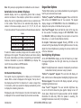
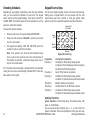
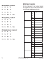
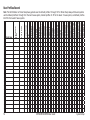
Asterisks display next to a programming option that is already
selected. As shown in the example, options that are selected to
display the current programming selection have an asterisk next
to the number. Those that are not selected simply display the
number. In the Areas example, areas 3, 8, 9, 15, 19, 23, 25, and
31 are not selected. The area numbers with asterisks are selected.
Areas
*1 *2
3 *4
*5 *6 *7
8
9 *10 *11 *12
*13 *14 15 *16
*17*18
*21*22
25 *26
*29*30
19 *20
23 *24
*27 *28
31 *32
To select or deselect a number, simply enter the number using the
digit keys on the keypad. This same scheme is used when viewing
the panel armed status and other programming and operational
functions. Remember to press the COMMAND key to display the
rest of the area numbers on XR550 systems.
Note: XR150 Systems support 8 areas.
32-Character Name Display
Your system may be programmed to display up to 32-character
names. When a name is displayed at the keypad, the top line of
the display shows the first 16 characters. If a name is longer than
16 characters, after two seconds the display automatically scrolls
to display the remaining characters.
On Graphic Touchscreen keypads: Pressing OPTIONS on the
carousel until it glows displays the Setting Options screen. You may
adjust the Screen Brightness by pressing the arrows at either end
of the bar indicators.
Backlighting Brightness
At the SET BRIGHTNESS display, use the left Select key to lower
the keypad brightness. Use the right Select key to increase the
brightness.
Note: If the brightness level is lowered, it temporarily reverts back
to maximum intensity whenever a key is pressed.
Thinline™ or Aqualite™ keypads: This sets the LCD display, AC
LED, and the Green or Blue keyboard backlighting brightness level.
Wireless keypads: This sets the LCD display, keyboard, and logo
backlighting brightness level.
Clear Touch™ Keypads: The user selected brightness may
be set to off which allows the glass graphic display to turn off
If displayed as part of the Status List, the entire 32-character name (clear glass). Simply touch the glass anywhere and the backlight
is displayed for four seconds followed by the number and status.
illuminates for data entry. When the speaker is sounding, the
backlight illuminates at one-half (1/2) brightness.
Introduction
XR150/XR350/XR550 User Guide
7
Graphic Touchscreen Keypads: Set the backlight illumination and
AC Power/Armed LED brightness level. In the touchscreen display
below SET BRIGHTNESS, press the left < to lower and the right > to
raise the backlight brightness. If the brightness level is lowered,
it reverts to maximum intensity whenever the screen is pressed
during normal operation. If the screen is not pressed, and the
speaker has not sounded for 30 seconds, the user-selected standby
brightness level restores.
Internal Speaker Tone
Set the tone of the keypad internal speaker. At the SET TONE
display, use the top left Select key to make the tone lower. Use the
right Select key to make the tone higher.
Volume level
Set the volume level of the keypad internal speaker for key
presses. During alarm, trouble, and prewarn conditions, the
volume is always at maximum level. At SET VOLUME LEVEL, use the
left Select key to lower the keypad volume. Use the right Select
key to raise the volume.
Model Number
Thinline™, Aqualite™, Wireless, Clear Touch, and
Graphic Touchscreen Keypads:
The keypad model number, firmware version, and date display, but
cannot be changed.
Serial Number
Thinline™ Wireless Keypads:
The serial number assigned to the keypad displays. Press the Back
Arrow key to exit the User Options function.
Keypad Address
The current address assigned to the keypad displays, but cannot
be changed. Press the Back Arrow key to exit the User Options
function.
8
Special Keypad Tones
Your keypad also contains a small speaker that alerts you about
events as they occur on your system. For burglary alarms, as soon
as the first digit key is pressed to enter a user code, the keypad
tone stops. If a valid user code is not entered or an invalid user
code is entered within five seconds, the tone begins sounding
again. Below are brief descriptions of the different tones you hear
from the keypad.
Fire Alarm tone: A sweeping siren that sounds until the fire alarm
is silenced.
Burglary Alarm tone: A constant siren tone that continues until
the alarm is silenced.
Key press tone: A short beep each time you press a key on the
keypad and it is acknowledged by the system.
Prewarn tone: A pulsed tone that sounds when you open an entry
delay door on a system that is armed (turned on) reminding you
to disarm the burglary protection. The tone silences as soon as
the first user code digit key is pressed. If a valid user code is not
entered or an invalid user code is entered within five seconds, the
prewarn tone begins sounding again.
Exit tone: A pulsing tone that sounds during the exit countdown
just after arming all areas of your system to remind you to exit the
premise. At ten seconds prior to the end of the countdown, the
rate of pulsing increases.
Monitor tone: A pulsed tone for one second, one pulse only that
sounds whenever a door or window is opened while you are using
the zone monitor function from the User Menu. See Zone Monitor.
Note: When toggling to a RMV monitor state, the Zone Monitor
tone does not sound.
XR150/XR350/XR550 User Guide
Introduction
Trouble tone: A steady tone indicating a trouble condition on your
system. Press a Select key to silence.
What to do when the trouble tone sounds
You can silence the trouble tone by pressing any key.
This only silences the keypad and does not correct the
condition that originally caused the trouble.
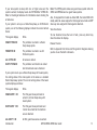
DMP Wireless
4-Button Layout
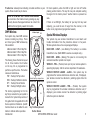
Your system may have DMP wireless
devices including key fob(s). There
are three types of DMP wireless key
fobs available:
4-Button Model 1145-4-B Key Fob
2-Button Model 1145-2-B Key Fob
1-Button Model 1145-1-B Key Fob
The drawing shows the button layout
for all three models. Each button
on the key fob is programmed to
perform a specific action. The button
names are listed below.
TOP = the Key Fob Top button
BTM =the Key Fob Bottom button
LFT = the Key Fob Left button
RGT =the Key Fob Right button
The button programming list for the
key fob(s) connected to your system is
located in the System Setup section of
this guide. Refer to Appendix D for LED
Status operation information. Specific
function labels can be added to each
button to indicate button operation.
Introduction
If there is no LED light, the battery for your key fob may need
replacing, you could be out of range from the receiver, or the
button is not programmed (programmed unused).
LED
Special Wireless Displays
Your system may use wireless transmitters to send alarm and
trouble information from the protection devices to the panel.
Wireless systems have a few unique keypad displays.
TOP
LFT
For best operation, allow the LED to light and turn off before
pressing another button. The key fob may not complete sending
the signal for the button press if another button is pressed too
soon.
BACK DOOR - LOBAT - (Low Battery) The battery in a wireless
transmitter is low. (BACK DOOR is used as an example only.)
RGT
BACK DOOR - MISNG - (Missing) The panel is not receiving the
wireless transmitter periodic test report.
BTM
WIRELESS - TRBL - (Trouble) Some part of your wireless system is
operating improperly. Call the service department for assistance.
Connect Keyring or Lanyard Here
2-Button Layout
1-Button Layout
TOP
TOP
WIRELESS RECEIVER JAMMED - ALARM - Your system may be
programmed for wireless interference detection and, if displayed,
your wireless receiver has detected a jamming signal while the
system is armed.
WIRELESS RECEIVER JAMMED - TRBL - (Trouble) Your system
may be programmed for wireless interference detection and, if
displayed, your wireless receiver has detected a jamming signal
while the system is disarmed.
BTM
Key Fob Examples and
Button Names
XR150/XR350/XR550 User Guide
9
Special Keypad Displays
ENTER CODE OR PRESENT CARD
As you use your system, you occasionally see a keypad display
that asks you to enter a code or that describes a condition on the
system. Below are some examples of the keypad displays:
ALARM
A 24-hour zone (for example fire or panic) or an armed burglary
zone has been tripped. Your system may sound bells or sirens.
TRBL (TROUBLE)
There is a problem with a protection device or system component.
This display is accompanied by a description of the problem.
ALARM NOT SENT
The alarm signal was aborted and was not sent to the central
station because a valid user code was entered to disarm the
system before the alarm signal was sent to the central station.
Also, your system may be pre-programmed at installation to send
an Abort signal to the Central Station that an alarm occurred but
was not sent because the user entered a code before the delay
time expired.
ALARM CANCELLED
An Alarm signal just sent to the central station was cancelled
because a valid user code was entered to disarm the system after
the alarm was sent. Also, an Alarm Cancel signal is sent to the
Central Station.
ALARM VERIFIED
A valid burglar alarm has occurred and has been manually verified
by the user. The alarm system also transmits a VERIFY message to
the Central Station.
10
The system requires you to enter your user code or present your
user card/proximity credential to a keypad or card reader. User
codes or reads can be required for turning your system on (arming),
turning your system off (disarming), and many other functions.
As you enter your user code, the keypad display shows an asterisk
(*) in place of each digit pressed. This keeps others from seeing
your user code on the display as it is entered.
TRY AGAIN OR INVALID CODE/CARD/PIN
The user code, card read, or PIN you have used is not recognized
by the system or is not authorized in their profile for that function.
Check the User Code or PIN, or present the card to the reader
again.
INVALID PROFILE
All user codes have a profile that allow the user to only access
certain functions. When users attempt functions outside their
authority, the INVALID PROFILE message displays.
INVALID AREA
A user has attempted a door access for an area they are not
assigned.
INVALID TIME
A user code assigned to a specific schedule is entered outside of
the valid schedule. See Schedules and User Codes.
ARMED AREA
A user has attempted a door access to an armed area to which they
do not have arming and disarming authority.
FAILED TO EXIT (ANTI-PASSBACK)
Anti-passback requires users to properly exit (egress) an area they
have previously accessed. If they fail to exit through the proper
XR150/XR350/XR550 User Guide
Introduction
card reader location, they are not granted access on their next
attempt. A Failed to Exit message appears when a user assigned
the anti-passback option attempts to re-enter an area which
they did not exit properly. The user must exit the area through
the proper door. If not possible, your system administrator should
select the Forgive option in the User Codes menu option.
SYSTEM TROUBLE or SERVICE REQUIRED
There is a problem with one or more of the components in your
system. Contact our service department as soon as possible.
SYSTEM BUSY
The system is performing another task of a higher priority. This
usually only takes a few moments.
TEST IN PROGRESS
The system is currently being tested by an installation or service
technician.
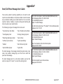
Cell Phone Messages
Understanding Security System Terms
Throughout this guide, and in some displays on your keypad, you
may see certain words or phrases that might be unfamiliar. Below
are some terms you may see here and on your keypad display:
Access (Door Access)
Entry/Exit doors that are used to restrict access to the building
or provide door access to authorized users. When a user code is
entered at the keypad by entering a code or presenting a card to
a reader, the system verifies authority and unlocks the door for a
short period of time. See Easy Entry User’s Guide in Appendix E.
Areas
An area is made up of burglary zones that can be armed or
disarmed together. One area might consist of the office doors and
windows. When you arm the office, these zones arm together and
sound an alarm if opened.
Arming
Your system may be programmed at installation to send a variety
of messages to your personal cell phone.
The message option uses your security system’s reporting capability
to send reports using a cell phone number in much the same way
as someone sending an email would do. You can receive reports of
alarms, troubles, or system arming and disarming and know at a
glance your system status. See Appendix F for more information.
Turns on the burglary protection in one or more areas of the
system. When armed, the system is able to sound alarm bells or
sirens and, if monitored, send alarm reports to a central station
when a burglary zone is tripped.
MyAccess™ Text Messaging Commands
Your system can also be programmed to automatically send
alarm, trouble, and arming and disarming reports to a central
station. Operators at the central station dispatch the appropriate
authorities or contact you with the specific event information.
Your system may be programmed to allow simple text messages to
be sent to the security system to perform basic user operations.
By texting a message from your cell phone or PDA, the following
actions can be performed: Arm/Disarm, check Armed Status,
Cancel Alarm, and turn Outputs On/Off. See Appendix F for more
information.
Introduction
Fire, panic, and other 24-hour devices are always turned on and do
not need to be armed.
Central Station Monitoring
XR150/XR350/XR550 User Guide
11
Disarming
Turns off one or more areas of the system. When disarmed, the
system does NOT sound alarms or send alarm reports to a central
station when a burglary zone faults.
Fault
You may see the keypad display FRONT DOOR —FAULT. This means
that there is a problem with the front door, such as the door being
open when you are arming the system. If you see a —FAULT display,
attempt to correct the problem (in this case shut the door). After
the zone is in a normal state, you may arm the system. You may
also bypass the zone and then arm the system.
Zone
A zone refers to one or more protected openings (doors or
windows) or protection devices (motion or glassbreak detectors)
grouped together under the same zone name and number.
Often, similar devices in the same general location share the same
zone. For example, the windows on the east side of the premises
can all be grouped together in a zone named E. WINDOWS.
Instant Zone
Interior protection devices and perimeter devices, such as exterior
windows, passive infrared detectors (PIR), and non entry doors,
are typically not programmed with delay times. If these zones are
tripped while the system is armed, an alarm instantly occurs.
24-hour Zone
A 24-hour zone is not turned on or off by arming or disarming your
system. Some examples of 24-hour zones are fire zones, panic
zones, and temperature control zones.
time to allow you to enter or exit without setting off the alarm.
When you arm the system, activity on this zone is ignored until
the exit delay time expires. Once that time has expired and the
system is fully armed, opening the door causes the panel to start
the entry delay time. During the entry delay time, you must enter
a valid user code to disarm the system or an alarm occurs.
Status
Status is a feature that automatically displays the armed or dis
armed status of your system on the keypads. Alarm or trouble
conditions on a zone or a system monitor such as AC or battery
trouble can also display. There are two types of status information
available: Armed Status and Status List.
Status List
The keypad Status List displays any alarm or trouble condition on
a zone, and any trouble condition on an internal system monitor.
The system monitors include the AC power, battery power, panel
box tamper, printer, and phone lines. If more than one alarm or
trouble condition occurs at the same time, the keypad sequences
this information on its display.
If the alarm is from a 24-hour zone or a system monitor, it remains
in the Status List until it restores. If one or more armed burglary
zones trip at the same time, the last one to trip remains in the
Status List. This is to ensure that if a burglary has occurred the last
zone tripped remains displayed even if it has been restored.
Armed Status
Armed Status is the keypad display of the current armed condition
of areas within your security system.
If your system is set up as an Area system with areas one to eight,
Almost all systems have one or more doors through which you can the display shows: 1 2 3 4 5 6 7 8. When you arm areas 1, 3, 5, and
access the premises. These doors are programmed with a delay 7 the keypad displays: 1 3 5 7.
12
XR150/XR350/XR550 User Guide
Introduction
Entry or Exit zone
If your Area system is setup with nine or higher areas and the
system is armed, the display reads: ALL SYSTEM ON or SYSTEM ON.
Refer to Checking Armed Areas for information about checking the
armed areas.
If your system is set up as a Home/Sleep/Away or All/Perimeter
system, one of the following displays indicate the current Armed
Status:
The keypad displays
When
HOME SYSTEM ON
The perimeter is armed in a Home/
Sleep/Away system.
PERIMETER ON
The perimeter is armed in an All/
Perimeter system.
ALL SYSTEM ON
All areas are armed.
SLEEP SYSTEM ON
The perimeter and interior are armed but the bedroom area is disarmed.
Note: The XR150 system allows one guest house system while the
XR350 and XR550 allows two guest house systems.
Also, for keypads that include an Armed LED, the Armed LED is ON
steady when ALL areas assigned to that keypad are armed and OFF
when any area assigned to that keypad is disarmed.
View Zone Status
To view disarmed zones that are in fault, press any Select key
when the status list displays.
Browser Feature
Refer to Appendix B at the back of this guide for diagrams showing
you how to use the built-in browsers.
If your system is set up as a Home/Sleep/Away with Guest system,
the arming status of the main system is the same as a standard
Home/Sleep/Away system. The current arming status of the Guest
systems displays as follows:
The keypad displays
When
HOME GUEST 1 ON
The first guest house perimeter is armed in a Home/Sleep/Away with Guest system.
SLEEP GUEST 1 ON
The first guest house perimeter and interior are armed but the bedroom area is disarmed.
ALL GUEST 1 ON Introduction
All first guest house areas are armed.
XR150/XR350/XR550 User Guide
13
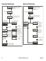
Arming and Disarming
General Arming Operation
Your system has been programmed to operate in one of four
configurations: Area, All/Perimeter, Home/Sleep/Away, or Home/
Sleep/Away with Guest.
• Area — Your burglary protection is divided into up to 32
areas. Each area can have a custom name, be turned on or off
independently of other areas, and limit access to only those
users with proper authority.
• All/Perimeter — Your burglary protection is divided into two
areas: Interior and Perimeter.
Perimeter arming is when you are staying inside but want
the comfort of knowing the exterior doors and windows are
armed. Perimeter arming allows you to move freely about
inside without setting off any interior alarms.
All arms both the Perimeter and the Interior of the system.
You want to arm both of these areas when leaving the building
and no one is left inside.
• Home/Sleep/Away — Your burglary protection is divided into
two or three areas: Perimeter, Interior, and Bedrooms.
Home (Perimeter) arming is when you are staying inside but
want the comfort of knowing the exterior doors and windows are
armed.
Sleep (Optional) (Perimeter and Interior) arms all areas except
those near bedrooms and nighttime areas.
Away (Perimeter, Interior, and Bedrooms) arms all three areas
when you leave the building and no one is left inside.
• Home/Sleep/Away with Guest — Your burglary protection has a
main house system and up to two guest house systems (XR150 has
1 guest house system while XR350 and XR550 offers 2). Each house
is separate and works just like the Home/Sleep/Away system
previously mentioned.
14
Regardless of which configuration is programmed, much of the
operation is similar. Throughout this guide, any differences
between the systems are noted for your convenience.
Arming Functions
Arming or Disarming: You can arm and disarm all areas at one
time or each area individually. You can only arm or disarm areas
authorized for your user code.
Arm All or Selective Arming: After entering your user code, the
system allows you to arm either all of the areas to which you have
access or one or more selected areas. If you choose to arm all
areas, the system begins verifying that all zones in those areas
are in a good condition. If you choose to arm selected areas, the
system prompts you to choose the areas you want to arm.
After making your arming selection, the keypad displays any zones
that are currently bypassed. These zones remain bypassed until
the system is armed and then disarmed. Any 24-hour zones in a
faulted condition also display.
Bypassing Zones: Before arming, the system verifies that all doors,
windows, and other protection devices to be armed are in normal
condition. If everything is verified, the system arms. If there is a
problem on one or more burglary zones, the system cannot arm
until the problem is corrected. If the problem is simply an open
door or window, correct the problem and try arming again.
If the problem cannot be corrected, you can force arm or bypass
the zone or wait until the zone can be repaired by a service
technician. A force armed zone is ignored by the system until
it restores to normal. A bypassed zone is ignored by the system
during the entire armed period. A zone remains bypassed until the
system is disarmed.
XR150/XR350/XR550 User Guide
Arming and Disarming
In some cases, you might see the keypad display FRONT DOOR —
FAULT. The keypad then displays priority zone which is a zone that
cannot be bypassed. The problem on the zone must be corrected
before the system can be armed.
When choosing to bypass a protection device or zone, there may
be a pre‑programmed maximum number of zones (up to 8) that
can be bypassed in an area when that area is being armed. This
limit is programmed at installation.
Arming Messages:
For Area systems the keypad briefly displays SYSTEM ON if only
selected areas are armed. The keypad briefly displays ALL SYSTEM
ON when all areas in the system are armed.
For All/Perimeter systems the keypad briefly displays PERIMETER
ON if only selected areas are arming. The keypad briefly displays
ALL SYSTEM ON when all areas in the system are armed.
For Home/Sleep/Away systems the keypad displays HOME SYSTEM ON
or SLEEP SYSTEM ON if only selected areas are arming. The keypad
briefly displays ALL SYSTEM ON when all areas in the system are armed.
For Home/Sleep/Away with Guest systems the main system arms
the same as a Home/Sleep/Away system. A keypad assigned to the
first guest house system displays HOME GUEST 1 ON or SLEEP GUEST 1
ON if only selected areas are arming. The keypad displays ALL GUEST
1 ON when all areas in the guest house system are armed.
Note: If your system uses a keyswitch to arm an area, the exit
delay time does NOT show on the keypad display.
When you arm both the Perimeter and Interior to leave the
building but then you do not exit by the time the exit delay ends,
the system automatically arms but the interior area(s) will remain
disarmed because you have not exited.
Should you exit the building and the door does not close properly,
your system may be programmed so that when the exit delay
countdown ends, then the entry delay starts and the bell will sound
to alert you to the situation. Enter your user code to stop the bell
and disarm the system. Rearm the system, exit the building, and
make sure the door is securely closed.
ONE MOMENT . . . Message: If your system is monitored, it
may be programmed to wait for the arming report transmission
to the central station before displaying the armed message. This
verifies your phone lines are working properly. While the system is
waiting for the transmission, the display reads ONE MOMENT... If
the report is received, the keypad displays the armed message. If
the report is not received, the keypad displays LOCAL ALARM ONLY
before displaying the armed message.
Note: Your system may be pre-programmed at installation to:
— send arming or zone bypassing reports to a central station
— arm and/or disarm specific areas at specific keypads.
Exit Delay: The keypad then displays the exit delay time as it counts
down. Your system may be pre-programmed at installation to beep
the exit delay tone at eight-second intervals until the last 10 seconds
when the keypad beeps at three‑second intervals. After exiting the
building, if you re-enter during the countdown the exit countdown
restarts, allowing additional time to then disarm or again exit the
building during the countdown. This restart can occur only one time.
When the exit delay time expires, all disarmed zones are armed.
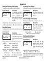
Press and hold the key fob button programmed for Arming or the Toggle
arm/disarm button. The Red LED two-second acknowledgement light
indicates All System On. The Green/Red two‑second acknowledgement
light indicates System On with some areas armed.
Arming
and Disarming
Key Fob Arming
XR150/XR350/XR550 User Guide
15
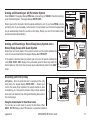
Key Fob Disarming
Press and hold the key fob button programmed for Disarming
or the Toggle arm/disarm button. The Green LED two-second
acknowledgement light indicates All System Off.
7c.Select BYPASS to bypass all faulted zones being displayed.
Note: 24-hour zones cannot be bypassed.
7d.Select STOP to stop the system from arming. Correct the
zone problem(s) and return to step 1.
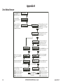
Area System Arming Operation
Arming the Area System
8. The display reads SYSTEM ON if at least one area in the
system is armed, and ALL SYSTEM ON if all areas in the
system are armed.
Area Assignment: Your security system has been set up into
separate areas. The number of areas and their names are listed on
the table in System Setup.
1. Press the COMMAND key until ARM DISARM is displayed.
2. Select ARM to arm the system.
3. Enter your user code if required. The keypad displays
ALL? NO YES.
4. Select NO to arm only selected areas. Go to step 5. Select
YES to arm all areas authorized for your user code. Go to
step 6.
5. If you selected NO in step 4, the display begins to list each
area to which you have access followed by NO YES.
Example: OFFICE NO YES
5a.Select YES for each area you want to arm.
5b.Select NO for each area you do not want to arm.
6. The system displays any bypassed zones or faulted 24-hour
or Priority zones. A faulted Priority zone cannot be armed.
7. At this point you can force arm or bypass any faulted zones.
A zone that is force armed is restored into the system if it later
returns to normal. A zone that is bypassed remains bypassed
until the system is disarmed. See steps 7a through 7d.
7a. If a problem exists on a zone, the zone name and problem is
shown followed by: OKAY BYPASS STOP.
7b.Select OKAY to force arm the faulted zone.
16
Your system may be programmed to require a user code that
has authorization to force arm or bypass a faulted zone. To
force arm or bypass a faulted zone, the system asks you to
enter a user code.
Note: Your system may be pre-programmed at installation
for the Instant Arming option.
9. The keypad next displays EXIT: ## INSTANT and begins to
count down the number of seconds remaining for you to exit.
When the delay expires, the exit zones are armed.
10. You can select INSTANT while EXIT: ## INSTANT is displayed
to immediately arm all exit zones and make them instant.
The keypad displays INSTANT.
Quick Arming
To quickly arm a desired area, enter the area number followed by
the COMMAND key when the ALL? NO YES option displays.
Checking the Armed Areas
After you have armed the system, you may press any Select key to
check the armed areas when ALL SYSTEM ON or SYSTEM ON displays.
The keypad then displays CHK ARMED AREAS: NAME NBR LIST.
Select NAME to list all of the armed areas by name. Select NBR to
enter the area number you would like to check. Select LIST to list
all of the armed areas by number.
XR150/XR350/XR550 User Guide
Arming and Disarming
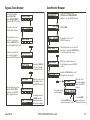
Area System Disarming Operation
While the system is armed, you can only enter the premises
through an entry/exit delay door without causing an alarm. After
opening the door, the keypad sounds a prewarn tone to remind you
to disarm the system. You must disarm the system before the entry
delay time expires or an alarm on the door zone occurs.
During the entry delay time, the keypad displays ENTER CODE: and
the name of the zone causing the entry delay. Enter your code to
disarm the system. Only those areas assigned to your code disarms.
Note: The prewarn tone silences as soon as the first user code digit
key is pressed. If a valid user code is not entered or an invalid
user code is entered within five seconds, the prewarn tone begins
sounding again.
Schedules: If you have programmed schedules for your system and
a code is entered outside of a schedule and that code does not have
authorization to disarm outside of schedules, the keypad displays
INVALID TIME. This lets users know that they are attempting to
disarm outside of their authorized time.
All or Selective Disarming: After entering your user code, the
system allows you to disarm either all of the areas to which you
have access or just selected areas. If you choose to disarm all
areas, the system automatically disarms them. If you choose to
disarm selected areas, the area names display on the keypad.
Alarm Display: After disarming, the keypad displays any zones
that tripped or any transmission problems that occurred during the
armed period. All burglary zones are then disarmed and any by
passed zones are automatically reset.
Disarmed Message: The keypad displays ALL SYSTEM OFF after the
system disarms.
Arming
and Disarming
Central Station Report: Your system may be pre-programmed at
installation to transmit a system disarming report to the central
station.
Door Access Disarming: Your system may be programmed to allow
area disarming when a card is presented to a door access reader
located outside of the building. Simply present your card to the
reader and after the card code is validated for the appropriate
authority, a door access is granted and your matching areas are
automatically disarmed. See the Easy Entry™ User’s Guide in
Appendix E.
Disarming the Area System from the keypad
1. Press the COMMAND key until ARM DISARM displays. During
entry delay this process starts at step 3.
2. Select DISARM to disarm areas.
3. The keypad displays ENTER CODE: .Enter your user code and
press COMMAND. The keypad displays ALL? NO YES.
4. Select YES to disarm all areas authorized for your user code.
Select NO to disarm only certain areas individually. The
keypad then displays the name of each area authorized for
your user code followed by the NO YES display.
Select YES to disarm the area displayed.
Select NO to not disarm the area and display the next area.
5. If you are disarming the system out of a normally scheduled
time and you have the authority to extend a schedule, the
keypad then displays 2HR 4HR 6HR 8HR. Select the number
of hours to extend the schedule.
Note: If you do not have the authority to extend a schedule,
this option does not display.
XR150/XR350/XR550 User Guide
17
6. After all areas have displayed and schedules extended, any
alarms or communication problems that occurred during the
armed period display.
7. If all areas have been disarmed, the keypad next displays ALL
SYSTEM OFF.
Quick Disarming
To quickly disarm a desired area, enter the area number followed
by the COMMAND key when the ALL? NO YES option displays.
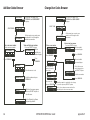
All/Perimeter System Arming
Area Assignment: Your security system is divided into two
separate areas. Motion detectors, inside doors, and other interior
protection devices are assigned to the Interior area while windows
and exterior doors are assigned to the Perimeter area.
Perimeter or All: When arming an All/Perimeter system, the
keypad displays PERIM
ALL. If you select ALL, you are arming
both the Perimeter and the Interior areas of the system. You will
want to arm both of these areas when leaving the premises with
nobody left inside. Selecting PERIM arms only the perimeter of the
system. Perimeter arming is when you’re staying inside but want
the comfort of knowing the exterior doors and windows are armed.
Perimeter arming allows you to move freely about inside without
setting off any interior alarms.
Instant: During the exit delay time, you can cancel the exit and
entry delays and cause all zones to be instant zones. Just press the
far right Select key under INSTNT while the exit delay is displayed.
This immediately arms the exit zones. However, no entry delay is
provided and an alarm will occur should an entry door be opened.
18
System Ready/System Not Ready
When all zones in the system are in a normal condition and can
be armed without bypassing, the keypad displays SYSTEM READY.
If there are one or more zones that are not in a normal condition,
the keypad displays SYSTEM NOT READY. Pressing any Select key
during this display shows the zone number and name allowing you
to investigate the problem.
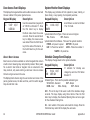
All/Perimeter Shortcut Key Arming
Arm Perimeter — Press 6 for 2 seconds.
Arm All — Press 1 for 2 seconds.
Arming an All/Perimeter System
1.
2.
3.
4.
Enter your 4-digit user code. The keypad displays PERIM ALL.
Select PERIM to arm the Perimeter area only.
Select ALL to arm both the Perimeter and Interior areas.
The keypad displays zones that have been bypassed prior to
arming and zones that are now in a faulted condition.
5. At this point you can force arm or bypass any faulted zones.
A zone that is force armed is restored into the system if it
later returns to normal. A bypassed zone remains bypassed
until the system is disarmed. See steps 5a through 5d.
5a. If a problem exists on any zones, the zone name and problem
display followed by: OKAY BYPASS STOP.
5b. Select OKAY to force arm the zone(s) before arming.
5c. Select BYPASS to bypass the zone(s) before arming.
5d. Select STOP to stop the system from arming. Correct the zone
problem(s) and return to step 1.
6. The keypad displays PERIMETER ON if only the perimeter is
being armed and ALL SYSTEM ON if both the perimeter and
interior are being armed.
XR150/XR350/XR550 User Guide
Arming and Disarming
7. If arming Perimeter, the keypad displays EXIT: ## INSTNT
and begins to count down the number of seconds remaining
for you to exit. When the delay expires, all zones are armed.
8. You can select INSTNT while EXIT: ## INSTNT displays to
immediately arm all zones and make them instant. The
keypad displays INSTANT. When you select INSTANT, any
entry/exit zone that trips immediately activates an alarm
and the exit delay countdown immediately stops.
9. When the system is fully armed, the keypad displays
PERIMETER ON for perimeter arming and ALL SYSTEM ON for
perimeter and interior arming.
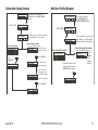
All/Perimeter System Disarming
Disarming: While the system is armed, you can only enter the
premises through an entry/exit delay door without causing an
alarm. After opening the door, the keypad sounds a prewarn tone
to remind you to disarm the system. You must disarm the system
before the prewarn tone expires or an alarm on the door zone will
occur.
During the prewarn tone, the keypad displays ENTER CODE:. Enter
your user code to disarm the system.
Schedules: If you have programmed schedules for your system and
a user code is entered outside of a schedule, the keypad displays
INVALID TIME. This lets the user know that they are disarming
outside of their authorized time.
Alarm Display: After disarming, the keypad displays any zones
that tripped or any transmission problems that occurred during the
armed period. All burglary zones are then disarmed and any by
passed zones are automatically reset.
Disarmed Message: The keypad displays ALL SYSTEM OFF after the
system disarms.
Arming
and Disarming
Central Station Report: A report of the system disarming can be
transmitted to the central sta
tion. This is optional and can be
programmed for you at any time.
Disarming an All/Perimeter System
1. During the entry delay time, the keypad displays ENTER
CODE:. Enter your 4-digit user code.
2. The keypad then displays any zones that went into alarm
or any communication problems that occurred during the
armed period.
3. The keypad next displays ALL SYSTEM OFF to confirm the
system is disarmed.
Disarming During an Alarm
1. While the alarm bell or siren sounds, enter your user code to
silence the alarm. The keypad tone silences as soon as the
first key is pressed.
For
a
burglary
alarm,
IS THIS A FALSE ALARM? CANCEL
the
keypad
VERIFY.
displays
This allows you to investigate the alarm prior to disarming
the system. This display remains on the keypad until a
selection is made, the Back Arrow is pressed, or the internal
system bell cutoff timer expires.
2. If a valid alarm has not occurred, select YES or CANCEL to
disarm the system and cancel the alarm.
The keypad next displays ALL SYSTEM OFF to confirm the
system is disarmed.
OR
If the alarm is valid, select NO or VERIFY and send a verify
message to the Central Station.
XR150/XR350/XR550 User Guide
19
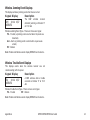
Home/Sleep/Away and Home/Sleep/Away with
Guest System Arming
Home/Sleep/Away and Home/Sleep/Away
with Guest Shortcut Key Arming
Area Assignment: Your security system is divided into two or three
separate areas. Motion detectors, inside doors, and other interior
devices are assigned to an Interior and Bedroom areas while
windows and exterior doors are assigned to a Perimeter area.
Arm Home — Press 3 for 2 seconds to arm the perimeter.
Arming the system: When arming a Home/Sleep/Away or a Home/
Sleep/Away with Guest system, the keypad displays HOME AWAY
or HOME SLEEP AWAY. If you select AWAY, you arm all areas of the
system. You will want to arm all areas when leaving with nobody
staying inside. Selecting HOME arms only the Perimeter of the
system. Perimeter arming is when you are staying inside but want
the comfort of knowing the exterior doors and windows are armed.
Perimeter arming allows you to move freely about inside without
setting off any interior alarms. Selecting SLEEP arms the Perimeter
and Interior devices but leaves devices near bedrooms or other
nighttime areas off.
Arming a Home/Sleep/Away or a Home/Sleep/
Away with Guest System
System Ready/System Not Ready Keypad
Displays
When all zones in the system are in a normal condition and can
be armed without bypassing, the keypad displays SYSTEM READY.
If there are one or more zones that are not in a normal condition,
the keypad displays SYSTEM NOT READY. Pressing any top row
Select key during this display shows the zone number and name
allowing you to investigate the problem.
20
Arm Sleep — Press 7 for 2 seconds to arm the perimeter and
interior areas and leave the bedroom area off.
Arm Away — Press 1 for 2 seconds.
1.Enter your 4-digit user code. The keypad displays
HOME SLEEP AWAY.
2. Select HOME to arm the Perimeter only.
3. Select SLEEP to arm the Perimeter and Interior.
4. Select AWAY to arm the Perimeter, Interior, and Bedroom.
5. The system displays any Bypassed zones or faulted 24-hour
or Priority zones. A faulted Priority zone cannot be armed.
6. At this point you can force arm or bypass any faulted zones.
A zone that is force armed will be restored into the system if
it later returns to normal. A zone that is bypassed will remain
bypassed until the system is disarmed. See 6a through 6d.
6a. If a problem exists on a zone, the zone name and problem is
shown followed by OKAY BYPASS STOP.
6b. Select OKAY to force arm the zone(s) before arming.
6c. Select BYPASS to bypass the zone(s) before arming.
6d. Select STOP to stop the system from arming. Correct the zone
problem(s) and return to step 1.
7. A Home/Sleep/Away system keypad displays HOME SYSTEM
ON if you selected HOME, SLEEP SYSTEM ON if you selected
SLEEP, and ALL SYSTEM ON if you selected AWAY.
A Home/Sleep/Away with Guest system keypad displays
HOME GUEST 1 (or 2) ON if you selected HOME, SLEEP GUEST
1 (or 2) ON if you selected SLEEP, and ALL GUEST 1 (or 2) ON
XR150/XR350/XR550 User Guide
Arming and Disarming
if you selected AWAY.
8. If arming the Perimeter, the keypad next displays EXIT: ##
INSTNT and begins to count down the number of seconds
remaining for you to exit. When the delay expires, the exit
zones are armed.
9. You can select INSTNT while EXIT: ## INSTNT is displayed to
immediately arm all exit zones and make them instant. The
keypad displays INSTANT.
Home/Sleep/Away and Home/Sleep/Away with
Guest System Disarming
Disarming: While the system is armed, you can only enter the
premises through an entry/exit delay door without causing an
alarm. After opening the door, the keypad sounds a prewarn tone
to remind you to disarm the system. You must disarm the system
before the prewarn tone expires or an alarm on the door zone will
occur.
Central Station Report: A report of the system disarming can be
transmitted to the central sta
tion. This is optional and can be
programmed for you at any time.
Disarming a Home/Sleep/Away or a Home/
Sleep/Away with Guest System
1.
During the entry delay time, the keypad
ENTER CODE:. Enter your 4-digit user code.
2. The keypad then displays any alarms or communication
problems that occurred during the armed period.
3. The keypad next displays ALL SYSTEM OFF to confirm the
system is disarmed.
Disarming During an Alarm
1. While the alarm bell or siren sounds, enter your user code to
silence the alarm. The keypad tone silences as soon as the
first key is pressed.
During the prewarn tone, the keypad displays ENTER CODE:. Enter
your user code to disarm the system.
For
a
burglary
alarm,
the
keypad
IS THIS A FALSE ALARM? CANCEL VERIFY.
Schedules: If you have programmed schedules for your system and
a user code is entered outside of a schedule, the keypad displays
INVALID TIME. This lets the user know that they are disarming
outside of their authorized time.
Alarm Display: After disarming, the keypad displays any zones
that tripped or any transmission problems that occurred during the
armed period. All burglary zones are then disarmed and any by
passed zones are automatically reset.
Disarmed Message: The keypad displays ALL SYSTEM OFF after the
system disarms.
Arming
and Disarming
displays
displays
This allows you to investigate the alarm prior to disarming
the system. This display remains on the keypad until a
selection is made, the Back Arrow is pressed, or the internal
system bell cutoff timer expires.
2. If a valid alarm has not occurred, select YES or CANCEL to
disarm the system and cancel the alarm.
The keypad next displays ALL SYSTEM OFF to confirm the
system is disarmed.
OR
If the alarm is valid, select NO or VERIFY and send a verify
message to the Central Station.
XR150/XR350/XR550 User Guide
21
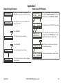
Extending Schedules
Keypad Shortcut Keys
Depending on your system programming, when the open schedule
ends, you can extend the schedule to a later time. The keypad
buzzer sounds and the keypad displays “area name” and LATE or
CLOSING TIME!. This reminds users still on the premises to arm the
system or extend the schedule.
Your two-line display keypads provide one‑button shortcut keys.
Holding down a keypad button for two seconds until the tone
sounds allows you to arm, monitor, or reset your system. These
options can still be accessed through the User Menu if desired.
Sensor Reset
(Fire Reset)
To extend the system schedule:
1. Press any Select key. The keypad displays ENTER CODE: - .
2. Enter your code and press COMMAND or present your access
card to a valid reader.
3. The keypad then displays 2HR 4HR 6HR 8HR. Select the
number of hours to extend the schedule.
Note: If the system is not armed by the scheduled closing
time, a Late to Close report is sent to the central station. If
the schedule is extended, a Schedule Change report may be
sent to the central station.
For information about extending a schedule before the scheduled
closing time is reached, see Extending Schedules (EXT) in the User
Menu portion of this guide.
Away
All
Monitor
(Chime)
1
AB
5
9
O
MN
YZ
2
DE
6
PQ
F
R
3
GH
7
ST
I
U
0
4
L
JK
8
VW
Home
X
CMD
Perimeter
Sleep
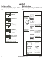
Keypad Shortcut Keys
Keypad Key
Arming System Operation
Press Key 1
Arm Away for Home/Sleep/Away systems
Arm Away for Home/Sleep/Away with Guest systems
Arm All for All/Perimeter systems
Press Key 2
Sensor (Fire) Reset on all systems
Press Key 3
Arm Home for Home/Sleep/Away systems
Arm Home for Home/Sleep/Away with Guest systems
Press Key 5
Monitor (Chime) on all systems
Press Key 6
Arm Perimeter for All/Perimeter systems
Press Key 7
Arm Sleep for Home/Sleep/Away systems
Arm Sleep for Home/Sleep/Away with Guest system
Arming Function
22
C
System Operation: Home/Sleep/Away, Home/Sleep/Away with
Guest, or All/Perimeter.
You can use the Arming shortcut keys, 1, 3, 6, and 7 when the
system is disarmed. You may be prompted to enter your user code.
XR150/XR350/XR550 User Guide
Arming and Disarming
If any zones are faulted, select force arm or bypass. Refer to the
Arming Section for detailed arming operation.
Home/Sleep/Away and Home/Sleep/Away with Guest Arming
Arm Home — Press 3 for 2 seconds to arm the perimeter.
Arm Sleep — Press 7 for 2 seconds to arm the perimeter and interior areas and leave the bedroom area off.
Arm Away — Press 1 for 2 seconds.
All/Perimeter Arming
Arm Perimeter — Press 6 for 2 seconds.
Arm All— Press 1 for 2 seconds.
Sensor (Fire) Reset Function
System Operation: Area, Home/Sleep/Away, Home/Sleep/Away
with Guest, or All/Perimeter.
You can use the Sensor (Fire) Reset, shortcut key 2, when the
system is armed or disarmed. When pressed, detectors that have
latched due to an alarm condition are returned to normal function.
The keypad displays SENSORS ON and SENSORS OFF to acknowledge
the shortcut key press.
Note: You may be prompted to enter your User Code.
User Menu
Many system features are programmed into a User Menu that you
can access from any keypad. The menu requires you to enter your
user code and then it only shows those functions to which you have
access.
Accessing the User Menu
1. Press the COMMAND key, if the multi-language option is
enabled, the available languages display. Select the language
to use for text display.
2. Press the COMMAND key until MENU? NO YES displays.
3. Select YES. The keypad displays ENTER CODE: –. Enter your
user code and press COMMAND. You can now scroll down
through the list of system features available to you.
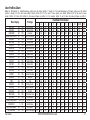
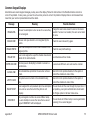
User Menu Options
The list below shows the User Menu options in order:
Menu Option
ALARM SILENCE
SENSOR RESET
Description
Silences an alarm bell or siren.
Resets smoke or glassbreak detectors that
have latched due to an alarm condition.
LOCKDOWN
Immediately locks all Public Doors.
DOOR LOCK/UNLOCKImmediately locks or unlocks a selected
Monitor (Chime) Function
door.
System Operation: Area, Home/Sleep/Away, Home/Sleep/Away DOOR ACCESS
Momentarily opens the keypad door lock
with Guest, or All/Perimeter.
relay.
You can use the Monitor (Chime), shortcut key 5, when the system is ARMED AREAS
Displays the name of any areas in the system
disarmed. When pressed, the Zone Monitor operation is initiated. As
that are currently in the armed state.
needed, refer to the Zone Monitor section. The keypad displays MONITOR OUTPUTS ON/OFF Allows you to turn on or off any of the
ON and chimes or displays MONITOR OFF and no tone is sounded.
outputs described in the System Setup
section of this guide.
Note: The Monitor (Chime) shortcut key applies to all Exit zones
Allows you to activate any Favorite
in an Area system and to all zones assigned to the perimeter in FAVORITES
described in the System Setup section of this
a Home/Sleep/Away, Home/Sleep/Away with Guest, or All/
guide.
Perimeter system.
Arming
and Disarming
XR150/XR350/XR550 User Guide
23
Z-WAVE SETUP
ZONE STATUS
BYPASS ZONES
ZONE MONITOR
SYSTEM STATUS
SYSTEM TEST
USER PROFILES
USER CODES
EXTEND CLOSING
SCHEDULES
TIME
DISPLAY EVENTS
24
Allows you to Add, List, Remove, Transfer,
and Rediscover Z-Wave devices in your
system. You can create Z-Wave Favorites,
Add, Edit, and Remove Z-Wave devices in
Favorites.
Allows you to see if a zone is either armed,
bypassed, in alarm, open, or shorted.
Allows you to Bypass a zone or reset an
already bypassed zone.
Allows you to add or remove a zone from the
monitor mode.
Displays the current condition of the system
AC power, backup battery, and optional
panel tamper.
Tests the system siren, communication to
the central station, and backup battery on
all XR150, XR350, and XR550 Series panels.
XR550N or XR550E panels allow additional
panic zone testing.
Allows you to add, delete, or change user
profiles.
Allows you to add, delete, or change user
codes.
Allows the Closing Check operation to delay
until the new closing time expires. This
allows the current schedule to ignore its
closing time and not send a LATE TO CLOSE
message to the central station.
Allows you to add, remove, or change
system schedules.
Allows you to change the Day, Date, or Time
that is currently programmed in the system.
Allows you to view or print the last 10,000
door accesses or 2,000 system events that
SERVICE REQUEST
FIRE DRILL
XR150/XR350/XR550 User Guide
occurred on your system.
Allows you to send a message to the Central
Station requesting service on the alarm
system.
Allows you to test the system fire bells.
User Menu
Alarm Silence
Silences the alarm bells or sirens during an alarm.
Alarm Silence allows you to turn off the alarm bells and sirens
connected to your system during an alarm. Using Alarm Silence
does NOT stop an alarm report from being sent to the central
station and does not reset any alarmed devices. Use the Sensor
Reset function to reset devices such as smoke detectors that have
latched in alarm.
Note: The keypad tone silences as soon as the first user code digit
key is pressed. You can silence the alarm by entering your user
code or by presenting your card to a reader during the Status List
display. If using a card, areas assigned to your code are disarmed
and door access occurs.
Using the Alarm Silence Function
1. Access the User Menu.
2. The keypad displays ALARM SILENCE?.
3. Press any Select key to silence the bells and exit the User
Menu.
Sensor Reset
Resets smoke or glassbreak detectors. Also clears Fire/Supervisory
alarm, trouble displays or low battery displays on systems using
wireless sensors.
Make sure all smoke is cleared from around the area of the smoke
detectors before performing a Sensor Reset to prevent the alarm
from occurring again.
Sensor (Fire) Reset Shortcut Key
All Systems — Press 2 for 2 seconds, then enter your user code if
required, to reset the system.
Resetting the Sensors
1. Access the User Menu.
2.Press COMMAND until SENSOR RESET? displays.
3. The keypad displays SENSORS OFF followed by SENSORS ON.
4. The keypad automatically exits the User Menu.
Lockdown
Your system may be programmed at installation for an access
control door to be a Public Door. Enabling Lockdown locks all
Public Doors from the keypad in an emergency situation.
Using Lockdown
1. Access the User Menu.
2.Press COMMAND until LOCKDOWN? displays.
3. Press any Select key. The door access relay is activated and
all Public Doors are locked.
4.Press COMMAND to return to the Status List display.
Sensor Reset is used to reset smoke and glassbreak detectors after
they have tripped. Once these detectors trip, they must be reset
before they can detect any additional alarm conditions. When you
select Sensor Reset, power to the detectors is temporarily removed
by the system allowing them to reset.
User
Menu
XR150/XR350/XR550 User Guide
25
Door Lock/Unlock
Using the Door Access
Locks and unlocks doors from the keypad.
Using Door Lock/Unlock
1. Access the User Menu.
2.Press COMMAND until DOOR LOCK/UNLOCK? displays.
3. Enter the door number and press COMMAND.
-ORPress the fourth Select Key to browse door names. Use the
COMMAND key to scroll through names and press any Select
Key when the desired door is displayed.
4. Press the Back Arrow key to return to the DOOR LOCK/
UNLOCK? display.
Door Access
Operates an electric door strike from the keypad.
Note: The door strike function is not available on Clear Touch™
keypads or the Model 7872 Graphic Touchscreen keypad.
Door Access is used to operate the door strike relay that is built
into some keypads. Power for the door strike is connected to the
keypad relay and can be interrupted by using the Door Access
function.
When Status List displays, you can operate Door Access by simply
entering your user code and pressing COMMAND. See Easy Entry™
User’s Guide in Appendix E. If you are using a keypad that has a
built-in card reader, you may simply present your card to be
allowed Door Access.
Note: Your system may be pre-programmed at installation to
transmit a door access report to the central station.
26
1. Access the User Menu.
2.Press COMMAND until DOOR ACCESS? displays.
3. Press any Select key. The door strike relay turns on
momentarily.
4. The keypad returns to the Status List display.
Armed Areas Display
Displays all armed area names in the system.
The Armed Areas display lists all of the names of the armed areas
in your system at the keypads.
Using the Armed Areas Function
1. Access the User Menu.
2.Press COMMAND until ARMED AREAS? displays.
3. Press any Select key. The keypad displays the first armed
area name. To scroll through the list of armed area names,
press the COMMAND key.
4. If there are no armed areas, the keypad displays NONE.
Outputs On Off
This function is used to individually turn your system relay and door
access outputs ON and OFF. Your system may use these outputs
to control door access, interior and exterior lighting, heating, air
conditioning, or other appliances.
The names and numbers of the relays connected to your system
are located in the System Setup section of this guide.
Outputs can be turned ON or OFF regardless of the output settings
in Schedules.
XR150/XR350/XR550 User Guide
User Menu
Your system may be programmed to require that your user code
profile have access to areas assigned to the keypad. INVALID AREA
displays when your user code does not have access to the keypad’s
areas and the output does not turn on.
Favorite
Under certain conditions, some outputs cannot be turned
on. If you select a restricted output, the keypad displays
CANNOT TURN ON.
Allows you to activate a Z-Wave Favorite. Z-Wave devices can
be grouped together to create Favorites. Favorites can only be
activated, or turned on. A separate Favorite must be created to
change the conditions set by the first Favorite. For a complete
description on how to add a Favorite to activate, see Adding a
FAVORITE in Z-Wave Setup.
Note: Z-Wave Setup will not be available to the user if Outputs On
Off is not enabled for the User in User Profiles.
1. When FAVORITES? displays, press any Select key. The keypad
displays FAVORITE: -.
Turning the Outputs ON and OFF
2. Enter a Favorite number from 1-20. Pressing COMMAND
activates the Favorite.
1. Access the User Menu.
2.Press COMMAND until OUTPUTS ON/OFF? displays.
3. Press any Select key.
4. Enter the output number you want to turn ON or OFF. The
output number displays.
5. With the output number displayed, select ON or OFF. The
output then turns ON or OFF depending on your selection,
and remains in that state until you change it. The keypad
displays the first 12 characters of the output or door name
followed by either ON or OFF for four seconds to provide
visual verification of the action. Press the COMMAND key to
end the four second display.
6. The system automatically returns to the output or door
option and a new output can be selected to turn ON or OFF.
Refer back to step 4.
7. Press the Back Arrow key to exit the User Menu.
Browser Feature
If you are unsure of the output number, refer to
Appendix B at the back of this guide for a diagram showing you
how to use the built-in Outputs ON/OFF browser.
User
Menu
XR150/XR350/XR550 User Guide
27
Z-Wave Setup
Add Z-Wave Devices (ADD)
Your system may include a DMP Z-Wave controller module attached
at installation. The Z-Wave controller module allows short range
radio control of Z-Wave devices that you or your installation
company may provide such as lighting control modules, thermostat
controls, and door locks. Z-Wave Setup allows you to program
the system to control the Z-Wave devices. You may control your
Z-Wave devices from your iPhone/iPad or Android device using
the DMP Virtual Keypad App or from your keypad by activating a
Favorite from the Favorites User Menu.
Note: Outputs On Off must be enabled in the profile assigned to
the user to access Z-Wave Setup. See User Profiles in the
User Menu.
The available setup options are: Add, List, Remove, Favorites,
Transfer and Rediscover.
•
•
•
•
•
•
28
Select ADD to add a Z-Wave device to your system.
Select LIST to display a list of Z-Wave devices already added
and stored in your system.
Select REMOVE to completely remove a Z-Wave device from
your system.
Select FAV to Add, Edit or Remove a Favorite.
Select XFER to transfer Z-Wave device information from
another manufacturer’s portable Z-Wave controller to your
system.
Select REDISC to require your system to rediscover and
confirm radio communication with all of the added Z-Wave
devices.
This option allows you to ADD a Z-Wave device to your system. Once
added, a Z-Wave device may be assigned to a Favorite.
1. Access the User Menu.
2.Press COMMAND until ZWAVE SETUP? displays.
3. Press any Select key. The keypad displays ADD LIST REMOVE.
4. Select ADD. PROCESSING may briefly display. When PRESS
BUTTON ON DEVICE TO ADD displays press the program button
on the Z-Wave device. See the Z-Wave device’s documentation
for more information.
5. When the device information is received by the system, the
keypad beeps once and displays DEVICE FOUND.
6. Once added, the keypad displays the type of device and the
default device name. Press COMMAND.
7. Press any top row Select key and enter up to a 16 character
custom name for the device. See Entering Names in
Appendix D.
8. Press the COMMAND key to store the new name.
Note: A maximum of 232 Z-Wave devices can be added to the
system. When the maximum number of devices have been
added, the keypad displays ZWAVE TABLE FULL and no
additional Z-Wave devices may be added without removing
some existing devices.
List Z-Wave Devices (LIST)
This option allows you to edit the name of a Z-Wave device or
confirm radio communication with the Z-Wave device. When LIST is
selected, the first Z-Wave device stored in the system is displayed.
Remaining devices can be viewed by pressing the COMMAND key.
Lighting control modules, are displayed first, followed by door
locks and then thermostat controls.
XR150/XR350/XR550 User Guide
User Menu
The available LIST options are: Rename and Status.
• Select RENAME to enter up to 16 characters for a new device
name.
• Select STATUS to confirm radio communication with the
Z-Wave device.
RENAME Z-Wave Devices
1. Access the User Menu.
2.Press COMMAND until ZWAVE SETUP? displays.
3. Press any Select key. The keypad displays ADD LIST REMOVE.
4. Select LIST to display DEVICE LIST and the first Z-Wave
device stored. Press the COMMAND key to advance through
the list of Z-Wave devices.
5. Press any Select key to display DEVICE RENAME STATUS.
6. Select RENAME and enter up to 16 characters for a new
device name. See Entering Names in Appendix D.
7.Press COMMAND to save the new Z-Wave device name and
return to the DEVICE LIST.
STATUS of Z-Wave Devices
1. Access the User Menu.
2.Press COMMAND until ZWAVE SETUP? displays.
3. Press any Select key. The keypad displays ADD LIST REMOVE.
4. Select LIST to display DEVICE LIST and the first Z-Wave
device stored. Press the COMMAND key to advance through
the list of Z-Wave devices.
5. Press any Select key to display DEVICE RENAME STATUS.
6. Select STATUS to confirm radio communication with the
Z-Wave device.
7. The device name and OKAY displays when the device stored
in the system communicates.
User
Menu
8.Press the COMMAND key to return to the device list and
display the next device in the list.
9.If the device stored in the system does not communicate, the
device name and FAILED displays. Press the COMMAND key
and REMOVE FAILED DEVICE displays.
10.Select YES to remove the failed device from the system
memory. Select NO to leave the device in the system
memory and to return to the device list.
11. When the device has been removed, the device name and
REMOVED is displayed and the system no longer tries to
communicate with the Z-Wave device.
Remove Z-Wave Devices (REMOVE)
Each Z-Wave device added to your system remains in your system
unless it is removed. This option allows you to remove Z-Wave
devices from your system.
1. Access the User Menu.
2.Press COMMAND until ZWAVE SETUP? displays.
3. Press any Select key. The keypad displays ADD LIST REMOVE.
4. Select REMOVE. PROCESSING may briefly display. When
PRESS BUTTON ON DEVICE TO REMOVE displays press the
program button on the Z-Wave device, the device name and
REMOVED is displayed to indicate the Z-Wave device has
been removed.
XR150/XR350/XR550 User Guide
29
Favorites (FAV)
Z-Wave devices can be grouped together to create a Favorite. This
option allows you to program up to 20 Favorites in your system and
then ADD, EDIT OR REMOVE up to 25 Z-Wave devices in a Favorite.
When activated from the FAVORITE user menu, a command is sent
to its Z-Wave Devices. A Favorite can only be activated, or turned on. A separate Favorite must be created to change the conditions
set by the first Favorite. For example, a Favorite called “Movie
Night” could lock the exterior doors, close the garage door, adjust
the temperature, and dim the lights in the family room to the
desired level. Another Favorite called “Wakeup” could then turn
on the lights, adjust the temperature, unlock the exterior doors,
and raise the garage doors.
Adding a FAVORITE
1. Access the User Menu.
2. Press COMMAND until ZWAVE SETUP? displays.
3. Press any Select key. The keypad displays ADD LIST REMOVE.
4. Press COMMAND again to display FAV XFER REDISC. Select
FAV and FAVORITE NUMBER: - is displayed.
5. Enter a Favorite number between 1 and 20 and press
COMMAND. If the Favorite number entered is unassigned,
*UNUSED* displays. If the Favorite is already assigned, you
may change the name or press the back arrow and enter a
new number.
6. Press any Select key and a cursor displays. Enter a Favorite
name up to 16 characters. To remove a Favorite, press
Command without entering a name.
7.Press COMMAND to save the Favorite and the Favorite name
and ADD EDIT REMOVE displays.
ADD Devices to FAVORITES
3. Press any Select key. The keypad displays ADD LIST REMOVE.
4.Press COMMAND again to display FAV XFER REDISC. Select
FAV and FAVORITE NUMBER: - is displayed.
5. Enter a Favorite number between 1 and 20 and press
COMMAND.
6. The Favorite number and name displays. Press COMMAND
and the Favorite Name and ADD EDIT REMOVE displays.
7. Select ADD and the first Z-Wave device stored in the
system that has not already been added to this Favorite is
displayed. Remaining devices can be viewed by pressing the
COMMAND key.
8. Press any Select key to assign the displayed device to the
Favorite. The device name and the current device settings
display. When added to a Favorite, a Z-Wave device can be
programmed to respond to various ON/OFF/LOCK/UNLOCK/
HEAT/COOL commands based on your desired settings. To
change a device setting, See Device Settings in Favorites.
Device Settings in FAVORITES
Lights
1. Press any Select key at SETTING: and ON OFF DIM
displays. Press the Select key under the desired
setting.
2. For ON or OFF setting, when selected, the Favorite
name and the next Z-Wave device stored in the system
displays.
3. For DIM setting, DIM LEVEL: with the current setting
displays. To change the setting, press any Select key
and enter the new level (1 - 10) and Press COMMAND.
4.The Favorite name and the next Z-Wave device stored
in the system displays.
1. Access the User Menu.
2.Press COMMAND until ZWAVE SETUP? displays.
30
XR150/XR350/XR550 User Guide
User Menu
Locks
1. P
ress any Select key at SETTING: and LOCK UNLOCK
displays. To change the setting, press the Select key
under the new setting.
2.The Favorite name and the next Z-Wave device stored
in the system displays.
Thermostats
EDIT Devices in FAVORITES
1. Press any Select key at SYSTEM: and OFF CL HT displays.
To change the setting of OFF, COOL or HEAT, press the
Select key under the new setting.
2. Select OFF to display FAN SETTING:.
3. Press any Select key and ON AUTO displays. Press the
Select key under the desired new setting to change.
4. Select CL to display COOL.
5. To change the setting, press any Select key, enter the
new temperature and press COMMAND.
6. Press any Select key and the keypad displays
FAN SETTING:.
7. Press any Select key and ON AUTO displays. Press the
Select key under the desired new setting to change.
8. Select HT to display HEAT.
9. To change the setting, press any Select key and enter
the new temperature and Press COMMAND.
10.
Press any Select key and the keypad displays
FAN SETTING:.
11. Press any Select key and ON AUTO displays. Press the
Select key under the desired new setting to change.
12.The Favorite name and the next Z-Wave device stored
in the system displays.
User
Menu
Note: A maximum of 25 devices can be assigned to each Favorite.
When attempting to add a device and the maximum number
of devices has been assigned, FAVORITE FULL is displayed.
No additional Z-Wave devices may be added to this Favorite,
however a new Favorite may be created and devices added
to the new Favorite.
1. Access the User Menu.
2.Press COMMAND until ZWAVE SETUP? displays.
3. Press any Select key. The keypad displays ADD LIST REMOVE.
4.Press COMMAND again to display FAV XFER REDISC. Select
FAV and FAVORITE NUMBER: - is displayed.
5. Enter a Favorite number between 1 and 20 and press
COMMAND.
6. The Favorite number and name displays. Press COMMAND
and the Favorite Name and ADD EDIT REMOVE displays.
7. Select EDIT and the first Z-Wave device stored in the Favorite
displays. Remaining devices can be viewed by pressing the
COMMAND key.
Note: Z-Wave devices are displayed by device type; Lights first,
followed Locks, and Thermostats last. By pressing the
COMMAND key you can scroll through the devices assigned to
the selected Favorite.
8. Press any Select key to display the device name and the
setting for the device.
9. To change the setting, See Device Settings in Favorites.
10. Once the device settings have been entered, the Favorite
name and the next Z-Wave device stored in the selected
Favorite displays.
XR150/XR350/XR550 User Guide
31
REMOVE Devices from FAVORITES
1. Access the User Menu.
2.Press COMMAND until ZWAVE SETUP? displays.
3. Press any Select key. The keypad displaysADD LIST REMOVE.
4.Press COMMAND again to display FAV XFER REDISC. Select
FAV and FAVORITE NUMBER: - is displayed.
5. Enter a Favorite number between 1 and 20, press COMMAND.
6. The Favorite number and name displays. Press COMMAND
and the Favorite Name and ADD EDIT REMOVE displays.
7. Select REMOVE and the first Z-Wave device stored in the
Favorite displays. Remaining devices can be viewed by
pressing the COMMAND key.
8. Press any Select key to remove the device from the Favorite.
REMOVE DEVICE FROM FAV? NO YES displays. When YES is
selected, the device is removed from the Favorite.
32
Transfer Controller (XFER)
This option allows the transfer of all existing Z-Wave devices that
are currently programmed in another manufacturer’s Z-Wave
portable controller to your system.
T
his operation will overwrite all Z-Wave devices that are
programmed in your system. This option typically occurs at
the time your DMP Z-Wave controller is installed.
Initiate the transfer at the other manufacturer’s Z-Wave portable
controller after starting the transfer on the DMP keypad. Z-Wave
devices are NOT overwritten until the transfer has been initiated
at the other manufacturer’s Z-Wave portable controller. The
transfer should not be stopped once the process has been initiated
from the other manufacturer’s Z-Wave portable controller.
Transfer Operation:
1. Access the User Menu.
2.Press COMMAND until ZWAVE SETUP? displays.
3.
Press
any
Select
key.
The
keypad
displays
ADD LIST REMOVE.
4.Press COMMAND again to display FAV XFER REDISC. Select
XFER. The keypad displays XFER WILL DELETE EXISTING
DEVICES then displays XFER CNTRL SURE? YES NO.
5. Select YES to to allow receipt of Z-Wave devices to your
system. The keypad displays TRANSFERRING Z-WAVE
DEVICES. Pressing the Back Arrow key cancels the transfer.
Select NO to exit the XFER menu and return to ZWAVE
SETUP?. All programming will still be intact on the DMP
Z-Wave controller and will cancel the transfer.
XR150/XR350/XR550 User Guide
User Menu
6. Initiate the transfer at the other manufacturer’s Z-Wave
portable controller. All Z-Wave devices are added to the
system with a default name (device type and number). A
16-character name may be assigned to the Z-Wave devices
after the transfer is complete. When the transfer is
complete the screen will display ZWAVE SETUP?.
Note: If TRANSMISSION FAILED displays on the screen, your
system memory is cleared of all prior Z-Wave devices
programming and will need to add each Z-Wave device
individually.
Rediscover (REDISC)
This option allows your system to search for and re-establish
communication with Z-Wave devices that may have failed to
communicate. Only Z-Wave devices already programmed into your
system are included in the rediscovery search. Any programmed
Z-Wave device that is not found during rediscovery will be deleted
from your system.
1. Access the User Menu.
2.Press COMMAND until ZWAVE SETUP? displays.
3. Press any Select key. The keypad displays ADD LIST REMOVE.
4.Press COMMAND again to display FAV XFER REDISC.
5. Select REDISC, the keypad displays REDISCOVERING ZWAVE
DEVICES while the system is searching for Z-Wave devices.
6. When the rediscovery is complete, the keypad returns to
ZWAVE SETUP?
User
Menu
Zone Status
Displays a list of armed, bypassed, or alarmed zones. Also allows
you to check the status of individual zones. Zone Status can be
used to give you a list of zones by category or display the current
status of an individual zone number. The four categories are:
• Armed Zones - zones that are currently armed.
• Bypassed Zones - zones that are currently bypassed.
• Alarmed Zones - zones that have gone into alarm during the
current or previous armed period.
• Number - enter the number of any zone to check its status.
Using the Zone Status Function
1. Access the User Menu.
2.Press COMMAND until ZONE STATUS? displays.
3. Press any Select key to display ARM BYPS ALR NBR.
4. Select ARM for a list of zones that are currently armed. You
can scroll through the list by pressing the COMMAND key.
5. Select BYPS for a list of zones that are currently bypassed.
6. Select ALR for a list of zones that have gone into alarm
during the current or previous armed period.
7. Press NBR and ZONE NO: - displays.
8. At the ZONE NO: - option, enter the zone number you want
to check and press COMMAND.
The zone number and name display followed by the zone
status. For example, a zone status for zone 1 might be
BACK DOOR - OKAY.
Below is a list of the zone status displays:
-OKAY= the zone is in a normal condition
-BYPAS= the zone is bypassed
-BAD=
the zone is in a bad or faulted condition
9. After displaying the zone status, ZONE: - returns for you to
enter another zone number.
XR150/XR350/XR550 User Guide
33
Browser Feature
Browser Feature
If you are unsure of the zone number or description, refer to
Appendix B at the back of this guide for a diagram showing you
how to use the built-in Zone Status browser.
If you are unsure of the zone number or description, refer to
Appendix B at the back of this guide for a diagram showing you
how to use the built-in Bypass Zones browser.
Bypass Zones
Zone Monitor
Allows you to bypass a zone prior to arming.
Bypassing is usually done when a zone cannot be restored to
normal. A significant benefit of bypassing a zone is to allow a zone
in a faulted or bad condition to be bypassed so arming can occur.
The faulted zone can be serviced the next day.
A zone can be bypassed only while it is disarmed. Fire, panic,
emergency, and supervisory type zones are always armed, so they
can never be manually bypassed.
Bypass Zones can also be used to reset a zone that has been
bypassed and restore it back into the system.
When Bypass Zones is selected, a report can be transmitted to
your central station.
During arming, when choosing to bypass a zone or device, there
may be a pre‑programmed maximum number of zones (up to
8) that can be bypassed in an area. This limit is programmed at
installation.
Using the Bypass Zones Function
1. Access the User Menu.
2.Press COMMAND until BYPASS ZONES? displays.
3. Press any Select key. The keypad displaysZONE: - RST BYPS.
4. To Bypass a zone, enter the zone number and select BYPS.
The zone number automatically disappears and a new zone
number can be entered. Refer back to step 3.
5. To Reset a zone, enter the zone number and select RST.
34
Allows the system to monitor selected disarmed zones (doors,
windows, or motion detectors) and display their name at the
keypad as they are faulted. This feature could be used to monitor
an access door.
Zone Monitor works with any disarmed zone and also sounds the
keypad monitor tone when the zone faults. The zone name displays
at all keypads designated for the area in your system.
You can place any combination of disarmed zones in Zone Monitor
but only the most recent zone faulted displays. The displayed zone
name clears automatically after a short time or when the zone is
armed.
Monitor (Chime) Shortcut Key
All Systems — Press 5 for 2 seconds when the system is disarmed.
This initiates the Zone Monitor operation for all Exit zones in an
Area system or all zones assigned to the perimeter in a Home/
Sleep/Away, Home/Sleep/Away with Guest, or All/Perimeter
system. The keypad displays MONITOR ON and chimes or displays
MONITOR OFF and no tone is sounded.
Testing your system’s burglary protection
After using the System Test function, place all zones in Zone
Monitor. Starting at the front door, go around and open and then
close each door and window. You should hear the keypad beep
each time. The keypad also displays the name of each zone as its
device is opened.
XR150/XR350/XR550 User Guide
User Menu
Once the protected doors and windows test is complete, walk in
front of each motion detector. The keypad should beep to confirm
the zone has tripped. If at any time during your weekly testing
a device does not cause the keypad to beep, call the service
department for assistance.
Using the Zone Monitor Function
1. Access the User Menu.
2.Press COMMAND until ZONE MONITOR? displays.
3. Press any Select key. The keypad displays ALL NBR or
PERIM ALL NBR.
4. Select PERIM to place all disarmed perimeter zones into
Zone Monitor.
4a. The keypad displays ALL? ADD RMV.
4b. Select ADD to add all disarmed zones to Zone Monitor.
4c. Select RMV to remove all disarmed zones.
5. Select ALL to place all disarmed zones into Zone Monitor.
5a. The keypad displays ALL? ADD RMV.
5b. Select ADD to add all disarmed zones to Zone Monitor.
5c. Select RMV to remove all disarmed zones.
6. Select NBR to enter a specific zone number for zone
monitor.
7. If you select NBR, the keypad displays ZONE: - ADD RMV.
7a. Enter any zone number and select ADD to add this zone.
7b. Enter any zone number and select RMV to remove this zone.
8. The zone number automatically disappears. You can then
enter a new zone number and repeat step 7a or 7b.
System Status
Displays the current condition of internal system hardware.
System Status shows the panel condition of AC power, battery
power, and optional panel tamper. When System Status is selected,
each monitor displays followed by OKAY or TRBL (Trouble) to
indicate the current condition.
Using the System Status Function
1. Access the User Menu.
2.Press COMMAND until SYSTEM STATUS? displays.
3. Press any Select key. The display starts listing each system
monitor and status.
For example: AC POWER - OKAY
Below are the System Monitor displays:
Keypad Display
AC POWER
What it monitors
AC power
BATTERY
Battery power
TAMPER
Panel box tamper
These are followed by either OKAY or TRBL (trouble).
If TRBL displays, call the service department for assistance.
4. The system then displays its firmware version, and then
exits the User Menu.
For example: VER_118_1/20/13 MODEL XR550
Browser Feature
If you are unsure of the zone number or description, refer to
Appendix B at the back of this guide for a diagram showing you
how to use the built-in Zone Monitor browser.
User
Menu
XR150/XR350/XR550 User Guide
35
System Test
Using the Panic Zone Test (XR550N/E Only)
System Test is used to test the battery, alarm bell or siren, and
communi
cation to a central station. The System Test function
begins automatically as soon as you select it.
Note: If an area is in an armed state, the system test will not
operate.
Using the System Test Function
1. Access the User Menu.
2.Press COMMAND until SYSTEM TEST? displays.
3. The keypad displays SYSTEM PANICS. Select SYSTEM.
3.The System Test begins automatically and the keypad
displays the following messages in this order:
1) BELL SOUNDING during a two second bell test
2) KEYPAD SOUNDING all keypads assigned to the same area
sound their burglary alarm tone for two (2) seconds during
the keypad sounder test
3) BATTERY - OKAY or BATTERY - TRBL to indicate the battery
condition
4)*TRANSMIT TEST NO: 1 during the transmit test
5) TRANSMIT OKAY or TRANSMIT FAILED to show the results of
the transmit test
6) TEST END to indicate the System Test is complete.
7) You can press the Back Arrow key to end the transmit test.
36
* The transmit test does not occur on local systems.
1. Access the User Menu.
2.Press COMMAND until SYSTEM TEST? displays.
3. Press any Select key. The keypad displays SYSTEM PANICS.
4. Select PANICS.
5. The Panic Zone Test begins automatically and the keypad
displays TRIPS: END.
During the Panic Zone Test, trip each panic zone (or button)
by pressing and holding the panic for 1 to 2 seconds.
Note: You do NOT have to hold the panic for 2 seconds in normal
mode. The Panic Zone Test takes additional time to display
when the system is in test mode.
Each time you trip a panic zone, the display number
increments and the keypad buzzer sounds for two seconds.
The number of panic zones tripped constantly displays until
the test ends or no panic zone activity has occurred for 20
minutes.
6. Select END to stop the Panic Zone Test.
7. PANIC TEST OKAY displays when the Panic Zone Test is
completed and all zones tested OK.
8. When the Panic Zone Test ends and a zone failed (did not
trip) during the test, the keypad displays the zone name
and number and the buzzer sounds for one second. Press the
COMMAND key to display the next failed zone.
Note: If testing a key fob, a message will not display if it fails, only
the verification message is displayed.
Note: During the Panic Zone Test, any zones that fail are not sent
to the receiver unless pre-programmed at installation to be
sent.
XR150/XR350/XR550 User Guide
User Menu
Note: Your system may be programmed to limit the Panic Zone Test
to only be performed during the Area 32 schedule.
User Profiles
Add, delete, or change User Profiles, that define the authority of
each user code in the system. Several characteristics define the
authority of each User Profile within the system. Always make sure
that at least one administrator in your system has a profile with all
authorities and all areas. Up to four profiles may be assigned per
user.
In All/Perimeter or Home/Sleep/Away operation, User Profiles will
not display in the User Menu. When adding User Codes, use the
default profiles 1 through 10. Refer to the User Profiles Chart.
In Home/Sleep/Away with Guest operation, the User Profiles option
does not display in the User Menu but when adding User Codes, enter
a profile number 1 through 9 for the main house system, profiles
11-19 for the Guest 1 house system, and profiles 21-29 for the
Guest 2 house system (XR550 only). Profiles 2-9 will default to have
Arming/Disarming for all eight areas, while profiles 12-19 and 22-29
only have Arm/Disarm assigned to Guest 1 and Guest 2 respectively.
Profiles 1, 11, and 21 do not have any Arming/Disarming authority
assigned. Refer to the User Profiles Chart.
Profile Number - Each profile may be assigned a unique number
from 1 to 99.
Profile Name - Each profile may be assigned a 32-character name.
The Profile Number is the default name.
Area Number - Each profile may be assigned specific areas of
the system for arming and disarming. When profiles 1 to 98 are
created, NO areas are assigned by default. The default for profile
99 is ALL areas assigned. Profile 99 is predefined in the system by
the factory. For the XR150 Series system you can assign areas 1 to
8. For the XR350 Series panel you can assign areas 1 to 16 and in an
XR550 Series system you can assign areas 1 to 32.
User
Menu
Access Area Number - Each profile may be assigned door access area
assignments. Default for profile 1 to 98 is NO areas assigned. Default for
profile 99 is ALL areas assigned. Profile 99 is predefined at the factory.
Output Group Assignment - Each profile may be assigned an
output group number from 1 to 10. Default for profile 1 to 98 is
NO output group assigned. Default for profile 99 is output group
10. Your system may by programmed to turn on an output group at
certain keypads when door access occurs.
User Menu Assignments - Each user profile may have any of the
menus assigned to it as shown in the User Profile Record. The User
Profile Record lists the user menu profile assignments and the
system functions users are allowed to access based on the profile
numbers assigned to their codes.
Adding User Profiles
1. Access the User Menu. Press COMMAND to USER PROFILES?.
2. Press any Select key. The keypad displays ADD DEL CHG.
Select ADD to add a new user profile.
3. At the PROFILE NO: - option, enter an unused profile number
and press COMMAND. The display changes to PROFILE NAME.
4. Press any Select key. Enter a profile name of up to 32
characters. Press COMMAND. See Appendix B.
5. At the ARM/DIS AREAS: option, select the area numbers for
arming and disarming assigned to this profile.
6. The keypad displays ACCESS AREAS: . Select the area
numbers assignment to allow door access for this profile.
Press the COMMAND key.
7. The keypad displays OUTPUT GROUP: -. Enter the number for the
Output Group assigned to this profile. Press the COMMAND key.
XR150/XR350/XR550 User Guide
37
8. The keypad displays each of the menus as shown in the
Profile Table for you to enable for this profile number. Select
YES or NO and press the COMMAND key to advance to the
next menu Selection.
9. When you have completed selecting all User Profile menu
assignments, the keypad displays the PROFILE ## ADDED
message for 4 seconds.
Browser Feature
Refer to Appendix B in this guide for a diagram showing you how to
use the Add User Profiles browser.
Changing User Profiles
1.Access the User Menu.
2.Press COMMAND until USER PROFILES? displays.
3. Press any Select key. The keypad displays ADD DEL CHG.
4. Select CHG to change a user profile.
5. At the PROFILE NO: - option, enter a profile number and
press COMMAND. The display changes to PROFILE NAME.
Note: The panel’s authority check determines whether your
User Profile is authorized to change another profile. The
message NO AUTHORITY appears if you are not authorized to
change the profile.
6. Press any Select key to display -. Enter a profile name of up
to 32 characters. The default Profile Name uses the Profile
Number. Enter the name and press COMMAND.
7. At the ARM/DIS AREAS: option, enter the area numbers for
arming and disarming assigned to this profile.
8. The keypad displays ACCESS AREAS: . Enter the area numbers
assignment to allow door access for this profile. Press the
COMMAND key.
9. The keypad displays OUTPUT GROUP: -. Enter the number
for the Output Group assigned to this profile. Press the
38
COMMAND key.
10. The keypad displays each of the menus as shown in the Profile
Table. You then enable or disable the menu function for this
profile number. Select YES or NO and press the COMMAND key
to advance to the next menu selection.
11. When you complete Selecting all User Profile menu
assignments, the keypad displays the PROFILE CHNGD
message for 4 seconds, indicating the profile is changed.
Browser Feature
Refer to Appendix B in this guide for a diagram showing you how to
use the Change User Profiles browser.
Deleting User Profiles
1. Access the User Menu.
2.Press COMMAND until USER PROFILES? displays.
3. Press any Select key. The keypad displays ADD DEL CHG.
4. Select DEL to delete a user profile.
5. At the PROFILE NO: - option, enter a profile number and
press COMMAND. The display changes to DELTD.
Note: User codes assigned to deleted profiles will not function.
Browser Feature
Refer to Appendix B in this guide for a diagram showing you how to
use the Delete User Profiles browser.
TEMP CODE
When you select YES for this menu option, the keypad displays
EXPIRATION DATE?. Enter the ending date for the profile to
expire. The keypad displays EXPIRATION TIME?. Enter the ending
time for the profile to expire. The keypad displays USER CODE?.
Enter a user code to activate.
XR150/XR350/XR550 User Guide
User Menu
ANTI PASS NO
ACCESS SCHEDULES
Anti-passback requires that you properly exit (egress) an area
previously accessed. If you fail to exit through the proper location
you cannot access it until you properly exit. Default is No. See
Failed to Exit (Anti-Passback) for more information.
EASY ARM/DISARM?
When entering your code, Easy Arm/Disarm allows you to
automatically arm or disarm all areas that are assigned to your
code. The ALL NO YES? option does not display when this option
is enabled.
This option allows you to assign up to eight Schedules to a
profile for door access. When the keypad displays FIRST ACCESS
SCHEDULE: - press any of the first three Select keys to enter the
desired Schedule number. Press the fourth Select key to browse
available Schedules in the LIST option. Press the Select key under
the desired Schedule to display the Schedule number then press
COMMAND. The keypad displays SECOND ACCESS SCHEDULE:
- repeat the same process for the third through eighth access
schedule and press COMMAND to return to the User Menu.
Note: To program a profile with anytime access, do not assign the
profile number to any Schedules.
RE ARM DELAY
RE ARM DELAY allows the entry of 0 to 720 minutes to be used to
delay automatic rearming when the user disarms an area outside
of schedule. If zero is selected, the rearming occurs based on
permanent programming in the panel. If another user enters a
valid user code or credential after the RE ARM DELAY countdown
has started, and their user profile RE ARM DELAY is greater, then
the RE ARM DELAY countdown starts over with the new time.
RE ARM DELAY is also used to delay a late to close message to the
central station when the panel does not use automatic arming.
If the user has Extend Schedule authority, 2HR 4HR 6HR 8HR displays at disarming. If the user does not make a choice, the RE
ARM DELAY is used to extend the schedule.
Application example: An exit door near the trash is scheduled
to be armed at all times. When the custodian needs to remove
trash, program 10 minutes for the activity. Or, an overhead door
only requires access when a delivery is made. Program up to 720
minutes to allow the loading dock supervisor to load or unload a
semi-truck.
User
Menu
XR150/XR350/XR550 User Guide
39
USE SECONDARY LANGUAGE
This option allows you to set the programmed secondary user
language to display when the Easy Arm/Disarm option is enabled
and the user presents their credential or enters their user code
at the Status List.
40
XR150/XR350/XR550 User Guide
User Menu
User Profiles Chart
Note: For All/Perimeter or Home/Sleep/Away systems use the default profiles 1 through 10. For Home/Sleep/Away with Guest systems use the default
profiles 1 through 9 for the main house system, default profiles 12-19 for the Guest 1 house system, and default profiles 22-29 for the Guest 2 house
system. Profiles 12-19 and 22-29 default to the same privileges as profiles 2-9. For example, profile 13 and 23 have the same privileges as profile 3.
Menu Display
ALM SLNC
SNSR RST
LOCKDOWN
DOOR LOCK/UNLOCK
DOOR ACS
ARM AREA
OUTPUTS
FAVORITES
ZN STATS
BYPAS ZN
ZONE MON
SYS STAT
SYS TEST
PROFILES
USR CODE
EXTEND
SCHEDULS
TIME
DIS EVNT
SERV REQ
FIRE DRILL
TEMP CODE
ANTI PASS
ACCESS SCHEDULES
RE ARM DLY
EASY ARM/DISARM
SEC LANGUAGE
User
Menu
NO
YES
NO
YES
NO
YES
NO
YES
NO
YES
NO
YES
NO
YES
F01 – F20
NO
YES
NO
YES
NO
YES
NO
YES
NO
YES
NO
YES
NO
YES
NO
YES
NO
YES
NO
YES
NO
YES
NO
YES
NO
YES
NO
YES
NO
YES
Sch. 1-99
0 – 720
NO
YES
NO
YES
Privilege
Alarm Silence
Sensor Reset
Lockdown
Door Lock/Unlock
Door Access
Armed Areas
Outputs ON/OFF
Z-Wave Favorites
Zone Status
Bypass Zones
Zone Monitor
System Status
System Test
User Profiles
User Codes
Extend Schedules
Schedules
Time
Display Events
Service Request
Fire Drill
Temp User Code
Anti-Passback
Access Time
Re-Arm Delay
Arm/Disarm
Preferred Language
1
2
3
4
No
Yes
Yes
Yes
Yes
Yes
No
No
Yes
No
No
Yes
No
No
No
No
No
No
Yes
No
No
No
No
No
No
No
Yes
Yes
Yes
Yes
Yes
Yes
No
No
Yes
No
No
Yes
No
No
No
No
No
No
Yes
No
No
No
No
No
No
No
Yes
Yes
Yes
Yes
Yes
Yes
No
No
Yes
No
No
Yes
No
No
No
No
No
No
Yes
No
No
No
No
No
No
No
Yes
Yes
Yes
Yes
Yes
Yes
No
No
Yes
No
Yes
Yes
Yes
No
No
No
No
No
Yes
No
No
No
No
No
No
No
Predefined Profile Number
5
6
7
8
9
10
11-98
99
Yes
Yes
Yes
Yes
Yes
Yes
Yes
Yes
Yes
No
Yes
Yes
Yes
No
No
No
No
No
Yes
No
No
No
No
No
No
No
No
No
Yes
Yes
Yes
No
No
No
No
No
No
No
No
No
No
No
No
No
No
No
No
No
No
No
No
No
No
No
No
No
No
No
No
No
No
No
No
No
No
No
No
No
No
No
No
No
No
No
No
No
No
No
Yes
Yes
Yes
Yes
Yes
Yes
Yes
Yes
Yes
Yes
Yes
Yes
Yes
Yes
Yes
Yes
Yes
Yes
Yes
Yes
Yes
No
No
Yes
No
No
Yes
Yes
Yes
Yes
Yes
Yes
Yes
Yes
Yes
Yes
Yes
Yes
Yes
No
No
Yes
No
No
Yes
No
No
No
No
No
No
No
XR150/XR350/XR550 User Guide
Yes
Yes
Yes
Yes
Yes
Yes
Yes
Yes
Yes
Yes
Yes
Yes
Yes
No
No
Yes
Yes
No
Yes
No
No
No
No
Yes
No
No
Yes
Yes
Yes
Yes
Yes
Yes
Yes
Yes
Yes
Yes
Yes
Yes
Yes
No
No
Yes
Yes
Yes
Yes
Yes
Yes
No
No
Yes
No
No
Yes
Yes
Yes
Yes
Yes
Yes
Yes
Yes
Yes
Yes
Yes
Yes
Yes
Yes
Yes
Yes
Yes
Yes
Yes
Yes
Yes
No
No
Yes
No
No
41
User Codes
Adding User Codes
This option allows you to add, delete, or change a user code. You
may also assign specific User Profiles to individual users.
1234
= User Number
34812
= User Code
89456
= PIN
John Smith = User Name
7 = Profile
User Number - Every user is numbered 1 through 9999. This
number identifies the user to the system and is transmitted to the
central station when the user arms or disarms areas.
User Code - Each user also has a 3- to 6-digit number to 999999, to
enter into the keypad when arming or disarming the system. Only
4-digit user codes can be assigned to All/Perimeter, Home/Sleep/
Away, or Home/Sleep/Away with Guest system users.
Note: A User Code cannot begin with zero and 3-digit codes cannot
begin with 98.
PIN - In an XR550E Card Plus PIN system, each user is assigned a
unique PIN (up to 6 digits) to enter into the keypad after presenting
their card/proximity credential to the reader when accessing
system functions.
User Names - Each code may also be programmed with the user
name. You may enter up to 32 characters for the name. As needed,
refer to Appendix C for Entering User Names information.
User Profile - The user is also assigned a Profile (1 to 99) by the
person administrating the system. The profile number determines
the areas and functions the user can access.
42
1. Access the User Menu.
2.Press COMMAND until USER CODES? displays.
3.
Press
any
Select
ADD DEL CHG BAT.
key.
The
keypad
displays
4. Select ADD or BAT (Batch) to add a new user code.
5. At the USER NUMBER: - option, enter a user number and
press COMMAND. The display changes to USER CODE: - .
Note: Do NOT program a code for user number 1 unless you
intend to use the Ambush function. See Ambush.
6. Enter a user code of 3 to 6 digits and press COMMAND. The
user enters this number to arm, disarm, etc. If using access
cards, present the card instead of entering a code. After
entering the code the keypad displays USER NUMBER ### as
the user name.
7. A 32-character name may be entered to identify the user.
Press any top row key to clear the current name. You may
then enter the new name. After entering the name press
COMMAND. See Entering Names in Appendix D.
8. The display changes to PROFILE NO: -. Select the profile
number to assign a set of authorized functions to the user
code as outlined in the Profile Table on the previous page.
Up to four profile numbers can be assigned to each user.
Note: On All/Perimeter or Home/Sleep/Away systems use
the default profiles 1 through 10. For Home/Sleep/Away
with Guest systems use the default profiles 2 through 9 for
the main house system, default profiles 12-19 for the Guest 1
house system, and default profiles 22-29 for the Guest 2 house
system.
XR150/XR350/XR550 User Guide
User Menu
9. At the PROFILE NO: - display, enter a profile number
from 1 to 99, and press COMMAND. The displays shows
USER # ADDED.
Note: If BAT (Batch) was chosen in step 4 instead of ADD,
the next available user number is automatically selected
and only steps 6 and 7 repeat. The User Profile assignment
is automatically selected for the next user based on the
previous user entered. This batch entry method speeds up
user entry in large systems.
Browser Feature
Refer to Appendix B at the back of this guide for a diagram showing
you how to use the Add User Codes browser.
Changing User Codes
To change a user code, you must have a user code with a profile
that has user code authority.
1. Access the User Menu.
2. Press the COMMAND key until USER CODES? displays.
3. Press any Select key. The keypad displays ADD DEL CHG
BAT.
4. Select CHG to change a user code.
5. At the USER NUMBER: - option, enter the user number to
change and press COMMAND.
Note: Changing a user code does not change the user number.
8. The display changes to PROFILE NO: -. Select the profile
number to assign a set of authorized functions to the user
code as outlined in the Users Profile Chart.
9. After entering the profile number, the keypad displays
USER # CHANGED for five seconds followed by USER
NUMBER: -. This display allows you to enter another user
number to change. Press the Back Arrow key twice to exit
the User Menu.
Changing Own User Code
Your system may be programmed at installation to allow users to
change their own user code.
1. Access the User Menu.
2. Press the COMMAND key until USER CODES? displays. Press
any Select key.
3. The display changes to USER CODE: * * * * * *. Press any
Select key.
4. Type your new user code. Press Command.
Browser Feature
Refer to Appendix B for diagrams showing you how to use the
Change User Codes browser.
Refer to the System Setup section for the number of user codes
available for your system.
6. The display changes to USER CODE: * * * * * *. Press any
Select key and enter the new user code. Press COMMAND.
7. The display then shows the current user name. Press any
top row key to clear. See Entering Names in Appendix D to
enter a new name.
User
Menu
XR150/XR350/XR550 User Guide
43
Deleting User Codes
1. Access the User Menu.
2.Press COMMAND until USER CODES? displays.
3.Press any Select key. The keypad displays ADD DEL CHG
BAT.
4. Select DEL to delete a user code from the system. To delete
a user code, you must have a user code with a profile that
has user code authority.
Note: Your system must have at least one user with user code
authority in order to be able to add or delete user codes. Be careful
not to delete all users with user code authority from your system.
Also, the user code used to enter the user menu to delete codes
cannot be deleted. In other words, you can not delete yourself.
5.At the USER NUMBER: - option, enter the user number you
want to delete and press COMMAND. The display changes to
USER # DELETED.
6. The display then changes back to USER NUMBER: - allowing
you to delete another user. Press the Back Arrow key twice
to exit the User Menu.
Browser Feature
Refer to Appendix B at the back of this guide for a diagram showing
you how to use the Delete User Codes browser.
Sending User codes to Z-Wave locks
Your system may be pre-programmed at installation to support ZWave door locks. This option allows you to send user codes of user
numbers 2-20 to all compatible Z-Wave locks. Once codes have
been received by the lock, a valid user code entered at the lock
(by user number 2-20) will lock the door or unlock and disarm the
system according to the user’s privileges.
44
1. Access the User Menu.
2. Press the COMMAND key until USER CODES? displays.
3. Press any Select key. The keypad displays ADD DEL CHG
BAT. Press COMMAND again to display FRGV SEND.
4 . Select SEND to send user codes of user numbers 2-20 to
all compatible Z-Wave locks on your system. The keypad
displays the progress of user codes being sent. The process
may take several minutes.
5. If all locks receive the user codes, the display will return to
the Status List.
6. If a lock does not receive the user codes, the keypad
displays CODES NOT SENT TO ALL LOCKS.
Forgive Failure to Exit
Failure to Exit is an Anti-passback violation in which a user assigned
with anti-passback has attempted to re-enter an area that they did
not exit through.
Forgive Failure to Exit removes the anti-passback violation. See
Failed to Exit (Anti-Passback) for more information.
1. After the USER CODES? menu is accessed and ADD DEL CHG BAT displays. Press COMMAND again to display FRGV SEND.
2. Select FRGV to forgive the Failure to Exit and press
COMMAND.
3. At the USER NUMBER:- option, enter the user number to
be forgiven and press COMMAND. The User Code Browser
described in Appendix B can help find the appropriate user
by name if you do not know the number.
4. The keypad displays USER XXXX FORGVN to confirm, then
returns to step 3 for the next user. Press the Back Arrow
key to exit this menu.
XR150/XR350/XR550 User Guide
User Menu
Ambush Code
Schedules
Your system may be programmed to allow user number 1 to be
used as an Ambush code. This Ambush code functions identically to
a standard code with the exception that it sends a silent alarm to
the central station. This silent alarm alerts the operator to a duress
situation at the premises and prompts immediate notification of
authorities.
Schedules are ideal for individual area auto arming and disarming
and for creating Opening/Closing windows during which users can
access the building or disarm the system.
Refer to the System Setup section of this guide to see if your
system is programmed for Ambush. If so, do NOT program a code
for user number 1 unless you intend to use the Ambush function.
Extend Closing
Extending schedules allows the Closing Check operation to
delay until the new closing time expires. This allows the current
schedule to ignore its closing time and not send a LATE TO CLOSE
message to the central station. This function is designed to allow
workers to stay later and does not extend door access authority.
The extended schedule erases when it expires.
1. Press any top row Select key at the EXTEND CLOSING option
to program Extended Schedules.
2. The keypad displays ENTER CLOSE TIME -: AM PM. Enter a
time to extend the current Closing Check open period.
3. To select AM or PM press the Select key under the desired
option. Press COMMAND to exit the menu.
Note: If the system is not armed by the scheduled closing time, a
Late to Close report is sent to the central station. If the schedule is
extended, a Schedule Change report is sent to the central station.
The Schedules function allows you to program into the system the
times at which you normally turn your burglary protection on and
off each day of the week. Your system may be pre-programmed
at installation to allow automatic arming and disarming. When
pre-programmed, you can enter a schedule for the arming and
disarming times.
If your system does not use automatic arming, you can use the
Closing Check/Extend feature with Schedules to help ensure your
system is armed manually at a specific time. This option sounds
the keypad buzzer and displays CLOSING TIME! or AREA LATE! when
a schedule expires. This reminds users still on the premises to arm
the system or extend the schedule to a later time.
Your system provides you with the following schedules menus:
1. Times allows you to create schedules 01-99 with days of
the week, begin/end times, and holidays.
2. Areas allows you to assign areas to pre-programmed
schedules set in the TIMES menu.
3. Door allows you to choose doors to assign schedules set in
the TIMES menu.
4. Output allows you to choose an output to schedules set in
the TIMES menu.
5. Holiday dates allow you to enter special dates that activate
Holiday Schedules that supersede all other schedules.
6. Favorites allows you to activate a Z-Wave Favorite (1-20).
User
Menu
XR150/XR350/XR550 User Guide
45
Setting Schedules
The keypad then displays END TIME? followed by the display
MON – : AM PM. Enter the new closing time and select
AM or PM. Select whichever day displays, for example,
MON, allows you to scroll through the days of the week and
create a schedule window that spans multiple days.
Note: You must enter a Begin and End time or the system
will not recognize the schedule.
The new schedule is now programmed into your system.
1. Access the User Menu and press COMMAND until SCHEDULES?
displays. Press any Select key.
2. The keypad displays TIMES AREAS DOOR. Press COMMAND
to display OUTPUT HOLIDAYS. Press COMMAND to display
FAVORITES. Select the function you want to program.
TIMES
The keypad displays ADD DEL CHG.
Adding a Schedule
Select ADD to enter a new schedule number.
1. Enter the Schedule number 01-99 that you want to add.
Press the COMMAND key to accept your Selection. You are
then given the option to enter a Schedule name. Press
COMMAND to proceed.
2. The keypad displays SUN MON TUE WED. Press the
COMMAND key to display THU FRI SAT HOL. Select the day
you want the schedule to begin. If you select HOL, go to
Setting Holiday ABC Schedules for additional instructions.
Note: After Selecting the day of the week or holiday for
the schedule to begin, the keypad displays any currently
programmed Begin and End times previously set for that
day. This feature allows you to review programmed
schedules at any time.
3. If Begin and End times already exist, the keypad then
displays DELETE KEEP. Select DELETE to enter new times.
4. The keypad then displays BEGIN TIME? followed by the
display MON – : AM PM. Enter the new opening time and
select AM or PM.
46
5. The keypad goes back to the SUN MON TUE WED display.
Press the Back Arrow key to enter another schedule.
6. To clear a schedule press DELETE and then AM when the
opening time is requested.
Press the Back Arrow key to exit the User Menu.
Delete a Schedule
Select DEL to delete a schedule number.
1. Enter the Schedule number 01-99 that you want to delete.
2. The keypad displays DELETE SCHEDULE SURE? YES NO.
Select YES to delete the schedule.
3. The keypad displays SCHEDULE NO: - DELETED and the
keypad prompts you for the next schedule number to be
deleted.
Press the Back Arrow key to exit the User Menu.
Change a Schedule
Select CHG to edit an existing schedule.
1. Enter the schedule number 01-99 that you want to change.
2. The keypad displays ENTER SCHEDULE and the schedule
name. To edit the name press any Select key to make
Enter all schedule times using a 12 hour clock. For example,
changes. Press COMMAND to proceed.
to enter 6 AM you would enter a 0 + 6 + 0 + 0 and select AM.
For 11 PM you would enter a 1 + 1 + 0 + 0 and select PM.
XR150/XR350/XR550 User Guide
User Menu
3. The keypad displays SELECT WEEK DAY and SUN MON TUE
WED. Press the COMMAND key to display THU FRI SAT HOL.
Setting Holiday ABC Schedules
Three Holiday Schedules are available. This allows an output,
area, or door to have three different schedules for holidays. For
example, Holiday Schedule A for those holidays when the building
stays closed, Holiday Schedule B for a day that only opens for a
5. The keypad goes back to the SUN MON TUE WED display. morning, etc. Also, Holiday Schedules can be used to cross multiple
Press the Back Arrow key to enter another schedule.
days. These schedules become active and supersede the current
Press the Back Arrow key to exit the User Menu.
day’s schedule when a Holiday Date occurs. See Setting Holiday
Dates (HOL).
Setting Area, Output, and Door Schedules
1. After you have accessed the SCHEDULES? menu and the
The Schedules function allows you to assign up to 8 different
schedule options, TIMES AREAS DOOR, display, press
schedule numbers to each area, output, and door access relay
the COMMAND key until the display changes to OUTPUT connected to your system. The schedule number allows the
HOLIDAYS. Press COMMAND once more and the display
opening and closing times for the area and on/off times for outputs
changes to FAVORITES.
and door access relays
2. Select HOLIDAY to program holiday schedules.
1. Access the User Menu.
3. The keypad displays HOL: A B C . Select A to set the first of
2.Press COMMAND until SCHEDULES? displays.
three holiday schedules.
4.
The keypad displays A - : AM PM.
3. After you have accessed the SCHEDULES? menu and the
Note: After Selecting the schedule, the keypad displays any
schedule options, TIMES AREAS DOOR, display, press
current times previously set for that holiday. This feature
the COMMAND key once more and the display changes to
allows you to review the programmed times.
OUTPUT HOLIDAYS. Select AREAS, DOOR, or OUTPUT.
5.
If
times display, the keypad then displays DELETE KEEP.
4. The keypad displays ENTER THE AREA/OUTPUT/DOOR
Select
DELETE to enter new times.
NUMBER:- , enter the area, output, or door number you
6.
The
keypad
then displays BEGIN TIME? This is followed by
want to assign a schedule. Press the COMMAND key.
the display – : AM PM.
5. The keypad displays SCHEDULE NO: -. Press any Select
Enter a new time and select AM or PM.
key and enter the schedule number (01 to 99). Press the
The display changes to END TIME? This is followed by the
COMMAND key.
display – : AM PM.
6. The keypad displays the next schedule number allowing you
Enter a new time.
to enter additional programming. To exit the user menu
Enter all schedule times using a 12 hour clock. For example,
press the Back Arrow key.
to enter 6 AM you would enter 0 + 6 + 0 + 0 select AM. For
11 PM you would enter 1 + 1 + 0 + 0 and select PM.
User
Menu
XR150/XR350/XR550 User Guide
47
4. Enter the Begin and End times for each day of the schedule.
Refer to Adding a Schedule for more information.
7. The keypad returns to HOL: A B C allowing you to enter A
B and/or C holiday schedule for the same Output or Door. Go
back to step 3 to add additional holiday schedules.
Setting Holiday Dates (HOL)
Setting Holiday Dates provides the system with dates in the year
when the normal opening and closing schedules are not used and
superseded by one of the Holiday Schedules A or B or C. When
the panel determines that it is a holiday, the Holiday Schedule
supersedes the current schedule for that day. Up to forty different
holiday dates can be entered.
1. After you access the SCHEDULES? menu and the schedule
options, TIMES AREAS DOOR, display, press the COMMAND
key once more. The display changes to OUTPUT HOLIDAY FAVORITES. Select Holiday to program Holiday dates.
2. The keypad display changes to HOL: xx mm/dd A. You can
now enter the month and day for the first holiday. Select
A to change to HOL B. Pressing again changes to HOL C.
Example: July fourth would be entered by pressing the
0704 keys. The keypad displays HOL:1 07/04 B.
3. To step to the next holiday number, press COMMAND. To
clear a holiday press any top row Select key when the
appropriate holiday number displays. Press the Back Arrow
key when HOL: 1 or the COMMAND key when HOL: 40
displays to exit the menu.
Favorites
Setting Favorites Schedules
Allows you to assign a Z-Wave Favorite to your programmed
schedule.
1. Access the User Menu.
2.Press COMMAND until SCHEDULES displays. COMMAND
through the options until FAVORITES displays. Press any
Select key.
2. TIME AREAS DOOR displays. press COMMAND to display
OUTPUTS HOLIDAYS. Press COMMAND to again to display
FAVORITES.
4. Press the first Select key to input a Favorite number or press
the last Select key to select from the list.
Activate Favorites
Allows you to activate a certain Z-Wave Favorite per your
programmed schedule.
1. Access the User Menu.
2.Press COMMAND until SCHEDULES displays. Press any Select
key.
2. Choose the Favorite to activate (1-20) and press COMMAND
to activate.
4. If the Favorite activation is successful, the keypad displays
FAVORITE XX ACTIVATED (XX = Favorite number entered). If
the Favorite activation is unsuccessful, the keypad displays
FAVORITE XX NOT PROGRAMMED.
Note: The Holiday Dates entered indicate the days of the year
when HOL schedules are used. For information on setting
holiday schedules for Area, Output, and Door, see Setting
Holiday ABC Schedules.
48
XR150/XR350/XR550 User Guide
User Menu
Setting the Date and Time
Allows you to change the current date and time displayed on the
keypad and used by the system.
Setting the System’s Date and Time
1. Access the User Menu.
2.Press COMMAND until TIME? displays. Press any Select key.
3. The keypad displays the current day and time. Press the
COMMAND key. The keypad displays the current date. Press
the COMMAND key to make any changes.
4. The keypad displays TIME DAY DATE.
5. Select TIME to change the time. The keypad displays
– : AM PM. Enter the current time and select AM or PM.
The display changes back to TIME DAY DATE.
6. Select DAY to change the day of week. The keypad displays
SUN MON TUE WED. Press the COMMAND key to display THU FRI SAT. Select the correct day. Use the Back Arrow key to
toggle between the different day of the week displays.
7. Select DATE to change the date. The keypad displays:
MONTH:- Enter up to 2 digits for the month.
Press COMMAND.
DAY:- Enter up to 2 digits for the day.
Press COMMAND.
YEAR:-Enter up to 2 digits for the year.
Press COMMAND.
The display returns to the TIME DAY DATE display.
Press the Back Arrow key to exit the User Menu.
User
Menu
Display Events
Allows you to review up to 12,000 past door access and system
events. There are six event types:
Zone Activity - Zone alarms, troubles, and restorals.
Opening and Closing - System arming and disarming.
User Code - Adding, deleting, and changing user codes.
Schedule Changes - Adding, deleting, and changing schedules.
Door Access - Each door access function used at a keypad.
Supervisory - Problems with system hardware components.
The system memory holds a maximum of 12,000 past events for 45
days. Any event older than 45 days automatically clears from the
system memory. Also, once the full 12,000 events are stored, any
new event causes the oldest event to be cleared. See Appendix A
for Display Events.
Service Request
Your user code profile may be programmed for Service Request.
This User Menu feature allows you to simply press any Select
key when SERVICE REQUEST? displays and have the system
automatically send a “Request for Service” message to the central
station. The display changes momentarily to REQUEST MADE to
confirm your request was sent.
XR150/XR350/XR550 User Guide
49
Fire Drill
Fire Drill is used to test the fire bells or fire horns in your system.
The Fire Drill test turns your system bell circuit on, but does not
send a message to the central station.
Starting a Fire Drill test
1. Access the User Menu.
2.Press COMMAND until FIRE DRILL? displays. Press any Select
key.
3. The keypad displays SURE? YES NO.
4. Select YES to start the Fire Drill test.
Ending a Fire Drill test
1. Enter your code at the keypad and press COMMAND to end
the Fire Drill.
2. The Fire Drill test automatically ends with ALARM SILENCE
or the programmed Bell Cutoff time.
50
XR150/XR350/XR550 User Guide
User Menu
System Setup Record
System Setup
This System Setup section allows you to track the current and
future status of the programmable options on your system. If
changes are made to the system, update the information contained
on these pages.
XR150 System
XR350 System
XR550 System
Your system operation configuration.
Area
Home/Sleep/Away
All/Perimeter Home/Sleep/Away with Guest
Your system is monitored by a central station.
Yes No
C/S Name: ________________________________________
Address: __________________________________________
City/State: ________________________________________
Emergency Phone: __________________________________
Service Phone: _____________________________________
Service Manager: ___________________________________
Your
Your
Your
Your
system sends Opening and Closing reports.
Yes No
system sends Zone Bypass reports.
Yes No
system sends Ambush reports.
Yes No
XR550E system uses Card Plus PIN operation.
Yes No
System
Setup
Keypad Record
Note: XR150 systems support 8 keypad devices. XR350 and XR550
systems support 16 keypad devices.
Device # Name
Areas
1________
___________________________ _____________
2________
___________________________ _____________
3________
___________________________ _____________
4________
___________________________ _____________
5________
___________________________ _____________
6________
___________________________ _____________
7________
___________________________ _____________
8________
___________________________ _____________
9________
___________________________ _____________
10_______
___________________________ _____________
11_______
___________________________ _____________
12_______
___________________________ _____________
13_______
___________________________ _____________
14_______
___________________________ _____________
15_______
___________________________ _____________
16_______
___________________________ _____________
XR150/XR350/XR550 User Guide
51
Which keypads display System Status?
1
2
3
4
5
6
7
8
9
10
11
12
13
14
15
16
Key Fob Button Programming
Enter the user name assigned to each key fob and the button
action programmed for each button in the table below. Refer to
the Introduction and Appendix D for more information.
Key Fob User Name
6
7
8
9
10
11
12
13
14
15
16
N/A
N/A
Which keypads provide Door Access reports?
1
2
3
4
5
6
7
8
9
10
11
12
13
14
15
16
52
Programmed Action
TOP
BTM
LFT
RGT
TOP
BTM
LFT
RGT
TOP
BTM
LFT
RGT
TOP
BTM
LFT
RGT
TOP
BTM
LFT
RGT
TOP
BTM
LFT
RGT
Which keypads display Armed Status?
1
2
3
4
5
Button
N/A
XR150/XR350/XR550 User Guide
System Setup
Area Names and Numbers Record
XR150 systems may be divided into 8 separate areas while XR350 systems may be divided into 16 separate areas. XR550 systems may be
divided into 32 separate areas. All/Perimeter systems are divided into two separate areas. Home/Sleep/Away and Home/Sleep/Away
with Guest systems are divided into two or three separate areas. Each area can have a name or description that displays at the keypad.
This can help you easily track events when and wherever they occur in your system.
AreaName
Area N ame
17 ____________________________________________________
1
____________________________________________________
2
____________________________________________________
18 ____________________________________________________
3
____________________________________________________
19 ____________________________________________________
4
____________________________________________________
20 ____________________________________________________
5
____________________________________________________
21 ____________________________________________________
6
____________________________________________________
22 ____________________________________________________
7
____________________________________________________
23 ____________________________________________________
8
____________________________________________________
24 ____________________________________________________
9
____________________________________________________
25 ____________________________________________________
10 ____________________________________________________
26 ____________________________________________________
11 ____________________________________________________
27 ____________________________________________________
12 ____________________________________________________
28 ____________________________________________________
13 ____________________________________________________
29 ____________________________________________________
14 ____________________________________________________
30 ____________________________________________________
15 ____________________________________________________
31 ____________________________________________________
16 ____________________________________________________
32 ____________________________________________________
System
Setup
XR150/XR350/XR550 User Guide
53
Z-Wave Device Name
1
____________________________________________________
21 ____________________________________________________
2
____________________________________________________
22 ____________________________________________________
3
____________________________________________________
23 ____________________________________________________
4
____________________________________________________
24 ____________________________________________________
5
____________________________________________________
25 ____________________________________________________
6
____________________________________________________
26 ____________________________________________________
7
____________________________________________________
27 ____________________________________________________
8
____________________________________________________
28 ____________________________________________________
9
____________________________________________________
29 ____________________________________________________
10 ____________________________________________________
30 ____________________________________________________
11 ____________________________________________________
31 ____________________________________________________
12 ____________________________________________________
32 ____________________________________________________
13 ____________________________________________________
33 ____________________________________________________
14 ____________________________________________________
34 ____________________________________________________
15 ____________________________________________________
35 ____________________________________________________
16 ____________________________________________________
36 ____________________________________________________
17 ____________________________________________________
37 ____________________________________________________
18 ____________________________________________________
38 ____________________________________________________
19 ____________________________________________________
39 ____________________________________________________
20 ____________________________________________________
40 ____________________________________________________
54
XR150/XR350/XR550 User Guide
System Setup
Z-Wave Favorites List
Your system has Favorites that can be used for various functions. The list below identifies the Favorite number, name, and devices.
Favorite # ___________ Favorite Name Devices included
____________ _________________________________________________________________________________
___________ ____________ _________________________________________________________________________________
___________ ____________ _________________________________________________________________________________
___________ ____________ _________________________________________________________________________________
___________ ____________ _________________________________________________________________________________
___________ ____________ _________________________________________________________________________________
___________ ____________ _________________________________________________________________________________
___________ ____________ _________________________________________________________________________________
___________ ____________ _________________________________________________________________________________
___________ ____________ _________________________________________________________________________________
___________ ____________ _________________________________________________________________________________
___________ ____________ _________________________________________________________________________________
___________ ____________ _________________________________________________________________________________
___________ ____________ _________________________________________________________________________________
___________ ____________ _________________________________________________________________________________
___________ ____________ _________________________________________________________________________________
___________ ____________ _________________________________________________________________________________
___________ ____________ _________________________________________________________________________________
___________ ____________ _________________________________________________________________________________
___________ System
Setup
____________ _________________________________________________________________________________
XR150/XR350/XR550 User Guide
55
Profile #
56
Profile Name
XR150/XR350/XR550 User Guide
Sec Language
Re Arm Delay
Eighth Access, 1-99
Seventh Access, 1-99
Sixth Access, 1-99
Fifth Access, 1-99
Fourth Access, 1-99
Third Access, 1-99
Second Access, 1-99
First Access, 1-99
Easy Arm/Disarm
Anti-passback
Temp User Code
Extend Schedules
Fire Drill
Service Request
Display Events
Time
Schedules
User Codes
User Profiles
System Test
System Status
Zone Monitor
Bypass Zones
Zone Status
Outputs On/Off
Armed Area
Door Lock/Unlock
Lockdown
Door Access
Sensor Reset
Alarm Silence
Disarm
Arm
Output Groups
Access Areas
Arm/Disarm
Areas
User Profiles Record
Note: For All/Perimeter or Home/Sleep/Away systems use the default profiles 1 through 10. For Home/Sleep/Away with Guest systems
use the default profiles 2 through 9 for the main house system, default profiles 12-19 for the Guest 1 house system, and default profiles
22-29 for the Guest 2 house system.
System Setup
User Codes Record
As you add new users or change current user codes, you can keep track of their profile number in the system. Use the following table to
track custom user codes in your system. Only 4-digit user codes can be assigned to All/Perimeter, Home/Sleep/Away, or Home/Sleep/
Away with Guest system users.
User #
System
Setup
User Name
Profile
#
User #
XR150/XR350/XR550 User Guide
User Name
Profile
#
57
Schedules Record
Schedule #
58
Schedule Name
Status
SUN
MON
TUE
WED
THU
FRI
SAT
Begin
End
Begin
End
Begin
End
Begin
End
Begin
End
Begin
End
Begin
End
Begin
End
Begin
End
Begin
End
Begin
End
Begin
End
Begin
End
:
:
:
:
:
:
:
:
:
:
:
:
:
:
:
:
:
:
:
:
:
:
:
:
:
:
:
:
:
:
:
:
:
:
:
:
:
:
:
:
:
:
:
:
:
:
:
:
:
:
:
:
:
:
:
:
:
:
:
:
:
:
:
:
:
:
:
:
:
:
:
:
:
:
:
:
:
:
:
:
:
:
:
:
:
:
:
:
:
:
:
:
:
:
:
:
:
:
:
:
:
:
:
:
:
:
:
:
:
:
:
:
:
:
:
:
:
:
:
:
:
:
:
:
:
:
:
:
:
:
:
:
:
:
:
:
:
:
:
:
:
:
:
:
:
:
:
:
:
:
:
:
:
:
:
:
:
:
:
:
:
:
:
:
:
:
:
:
:
:
:
:
:
:
:
:
:
:
:
:
:
:
_M
_M
_M
_M
_M
_M
_M
_M
_M
_M
_M
_M
_M
_M
_M
_M
_M
_M
_M
_M
_M
_M
_M
_M
_M
_M
_M
_M
_M
_M
_M
_M
_M
_M
_M
_M
_M
_M
_M
_M
_M
_M
_M
_M
_M
_M
_M
_M
_M
_M
_M
_M
_M
_M
_M
_M
_M
_M
_M
_M
_M
_M
_M
_M
_M
_M
_M
_M
_M
_M
_M
_M
_M
_M
_M
_M
_M
_M
_M
_M
_M
_M
_M
_M
_M
_M
_M
_M
_M
_M
_M
_M
_M
_M
_M
_M
_M
_M
_M
_M
_M
_M
_M
_M
XR150/XR350/XR550 User Guide
_M
_M
_M
_M
_M
_M
_M
_M
_M
_M
_M
_M
_M
_M
_M
_M
_M
_M
_M
_M
_M
_M
_M
_M
_M
_M
_M
_M
_M
_M
_M
_M
_M
_M
_M
_M
_M
_M
_M
_M
_M
_M
_M
_M
_M
_M
_M
_M
_M
_M
_M
_M
_M
_M
_M
_M
_M
_M
_M
_M
_M
_M
_M
_M
_M
_M
_M
_M
_M
_M
_M
_M
_M
_M
_M
_M
_M
_M
HOL A HOL B HOL C
:
:
:
:
:
:
:
:
:
:
:
:
:
:
:
:
:
:
:
:
:
:
:
:
:
:
_M
_M
_M
_M
_M
_M
_M
_M
_M
_M
_M
_M
_M
_M
_M
_M
_M
_M
_M
_M
_M
_M
_M
_M
_M
_M
:
:
:
:
:
:
:
:
:
:
:
:
:
:
:
:
:
:
:
:
:
:
:
:
:
:
_M
_M
_M
_M
_M
_M
_M
_M
_M
_M
_M
_M
_M
_M
_M
_M
_M
_M
_M
_M
_M
_M
_M
_M
_M
_M
:
:
:
:
:
:
:
:
:
:
:
:
:
:
:
:
:
:
:
:
:
:
:
:
:
:
_M
_M
_M
_M
_M
_M
_M
_M
_M
_M
_M
_M
_M
_M
_M
_M
_M
_M
_M
_M
_M
_M
_M
_M
_M
_M
System Setup
Holiday Date Record
Output Record
# Date (mm/dd) HOL (circle one)
# Date (mm/dd) HOL (circle one)
Your system has outputs that are used to control various functions
within the building or access around its perimeter. The list below
identifies the output numbers and device names.
1. ____/____
A or B or C
21. ____/____
A or B or C
2. ____/____
A or B or C
22. ____/____
A or B or C
3. ____/____
A or B or C
23. ____/____
A or B or C
4. ____/____
A or B or C
24. ____/____
A or B or C
5. ____/____
A or B or C
25. ____/____
A or B or C
6. ____/____
A or B or C
26. ____/____
A or B or C
7. ____/____
A or B or C
27. ____/____
A or B or C
8. ____/____
A or B or C
28. ____/____
A or B or C
9. ____/____
A or B or C
29. ____/____
A or B or C
10. ____/____
A or B or C
30. ____/____
11. ____/____
A or B or C
12. ____/____
Your system has up to 40 holiday dates available that supersede all
regular scheduled times for that day.
Output #
Output Name
___________
________________________________________
___________
________________________________________
___________
________________________________________
___________
________________________________________
___________
________________________________________
___________
________________________________________
___________
________________________________________
___________
________________________________________
___________
________________________________________
A or B or C
___________
________________________________________
31. ____/____
A or B or C
___________
________________________________________
A or B or C
32. ____/____
A or B or C
___________
________________________________________
13. ____/____
A or B or C
33. ____/____
A or B or C
___________
________________________________________
14. ____/____
A or B or C
34. ____/____
A or B or C
___________
________________________________________
15. ____/____
A or B or C
35. ____/____
A or B or C
___________
________________________________________
16. ____/____
A or B or C
36. ____/____
A or B or C
___________
________________________________________
17. ____/____
A or B or C
37. ____/____
A or B or C
___________
________________________________________
18. ____/____
A or B or C
38. ____/____
A or B or C
___________
________________________________________
19. ____/____
A or B or C
39. ____/____
20. ____/____
A or B or C
40. ____/____
Use the Output number in the User Menu when setting Output
Schedules or using the Outputs ON OFF option to manually toggle
A or B or C
the relays.
XR150/XR350/XR550 User Guide
59
System
Setup
A or B or C
About the Display Events Section
This section of the User’s Guide shows the Display Events items.
While in the Display Events function, use the COMMAND and Back
Arrow keys to go forward or backward through the list of events.
To view more information about each display, press the Select key
as directed in the explanations below.
Using the Display Events
1. Access the User Menu.
2. Press the COMMAND key until DISPLAY EVENTS? displays.
Press any Select key.
3. The keypad displays FRST LST PRT SRT. Select FRST (first)
to view the oldest to newest events. Select LST (last) to
view the newest to oldest events. If you select FIRST, use
the COMMAND key to scroll up through the events. If you
select LAST, use the Back Arrow key to scroll down through
the events.
Select SRT to sort through the Display Events log and collect
information specific to a user or system event.
Select PRT to print the complete Display Events log.
4. To use the Sort feature, select SRT. The keypad displays
FRST DATE: 8/21. Press any Select key and enter a 4‑digit
beginning date for the sort. Press COMMAND.
6. The keypad displays USER NUMBER: -. To sort events for a
particular user, enter their user number or press COMMAND
to sort for all users. To search for a user, press any Select
key then use the COMMAND and Back Arrow keys to browse
through the user names in the system. When the user you
want displays, press any Select key then press COMMAND.
7. The keypad next displays five event types that you can
include in the sort. Press the fourth Select key to display
YES when the event type name displays on the keypad.
Press COMMAND. The following are the sort event types:
ACCESSES = door accesses granted.
DOOR NUMBER = leave blank for all doors.
Note: If you select yes for access then only Door Access Granted
Events are included in the sort.
ZONE EVENTS = zone alarms, troubles, and restorals.
ARM/DISARM = arming and disarming events.
USER EVENTS = adding, deleting, and changing user codes.
SUPERVISORY = system hardware problems and door access
denied events.
8. After the last event type displays, the keypad again displays
FRST LST PRT SRT. You can now view or print the sorted
Display Events or press SRT to define a new sort.
5. The keypad displays LAST DATE: 10/17. Press any Select
key and enter a 4-digit ending date for the sort. Press
COMMAND.
60
XR150/XR350/XR550 User Guide
System Setup
Arming and Disarming Event Displays
Appendix A
Supervisory Event Displays
This displays any system area arming or disarming events.
This displays the date and time of an automatic test report.
Keypad Display
Keypad Display
ARM 5:10P10/17
WAREHOUSE
Description
The Warehouse was armed on
October 17 at 5:10 PM. Press any
Select key to display the area
number and user number, and
then any Select key to display the
user name.
Arming Event Types - There are two event types you may see:
ARM - User armed the system DIS - User disarmed the system
Zone Event Displays
This displays alarms, troubles, and other events that may occur on
your protection zones.
Keypad Display
ALR 10:23P 10/17
Basement door
Description
An alarm occurred on October 17
at 10:23 PM. Press any Select key
to see the zone number and zone
type.
Msg 11:58P 10/ 17
Auto recall
Description
The test report was sent to the
central station at the date and
time shown.
User Code Change Event Displays
This displays any addition, deletion, or change to a user code.
Keypad Display
Add 11:41A10/17
U:19byu:12
Description
User 19 added at 11:41 AM by
user 12. Select either user (US:)
number for the user name.
User Code Event Types - There are three event type you may see:
ADD - User added
DEL - User deleted
CHG - User code or authority level changed.
Zone Bypass Event Displays
This displays zone bypass events.
Keypad Display
Description
The east window zone
bypassed. Press any Select
for the zone number and
number. Press again for the
name.
was
Zone Type - There are seven possible zone types you may see:
Byp 5:18P10/17
key
FIRE - Fire
PANC - PanicBURG - Burglary
East window
user
EMRG - Emergency
SUPV - Supervisory
user
AUX1 - Auxiliary 1
AUX2 - Auxiliary 2
Event Types - There are seven event type you may see:
Bypass Event Types - There are three event types:
ALR - Alarm
TBL - Trouble
RST - Restore
BYP - Bypass
RST - Restore
FRC - Force Arm
FLT - Zone Fault
SVC - Service smoke detector
Note: You may sometimes see the user as SWG. This is short for
LOW - Low battery
MIS - Missing wireless transmitter
Swinger Bypass which is an automatic function that allows the
Note: LOW and MIS are for wireless systems only.
system to automatically bypass a zone.
Appendix
A
XR150/XR350/XR550 User Guide
61
Door Access Event Displays
System Monitor Event Displays
This displays the keypad address where a Door Access occurred and
the user number of the person granted access.
This displays any problems with the system AC power, battery, or
phone line(s), or any opening of a tampered panel box.
Keypad Display
Keypad Display
acc 5:18P10/17
3user:024
Description
User 24 accessed door (keypad) #3
at 5:18 PM on October 17. Press
the first Select key to display
the Door name where the access
occurred. Press the second Select
key to display the reason access
was denied. Press the third Select
key for the name of the device, or
the fourth Select key for the user
name.
tbl 11:41A10/17
power
Description
An AC failure occurred on October
17 at 11:41 AM.
System Monitor Event Types - There are two event types:
TBL - Trouble
RST - Restore
System Monitor Event Names - There are five system monitors:
POWER - AC power to panel
BATTERY - On panel
LINE 1 - Phone line number 1 LINE 2 - Phone line number 2
TAMPER - On panel box
Schedule Change Event Displays
About Door Access
Door Access is a feature available on certain keypads that contain
a built-in door releasing relay and proximity readers. When power
for an electric door strike or magnetic lock is connected to the
relay contacts, only users entering a valid user code can release
the lock and gain access to the area.
The Display Events feature logs the user number and name of the
person granted access, the date and time, and from which keypad
they entered their code.
This displays Changes made to the system schedules.
Keypad Display
S1 9:41A10/17
MONuser:024
Description
S1 schedule for Monday was
changed by user 24 at 9:41 AM on
October 17.
Schedule Types - There are five possible schedule types:
S1 S2 S3 S4 - Standard
OUT - Output
DOOR - Door
HOL - Holiday
EXT - Extend
MON - This is the day of the week in which the schedule change
occurred. The days display using three letters. Press the first
Select key to display the scheduled Opening time and once again
for the scheduled Closing time.
024 - User number of the person who made the change. Press the
third Select key under 024 to display the user name.
62
XR150/XR350/XR550 User Guide
Appendix A
Wireless Jamming Event Displays
This displays wireless jamming events that have occurred.
Keypad Display
ALM 11:41A10/17
WIRELESS
Description
The
DMP wireless
receiver
detected jamming on October 17
at 11:41 AM.
Wireless Jamming Event Types - There are three event types:
TBL - Trouble (a jamming event occurred when the panel was
disarmed)
ALM - Alarm (a jamming event occurred when any area was
armed)
RST - Restore
Note: Trouble and Restore events display WIRELESS as the device.
Wireless Trouble Event Displays
This displays events when the wireless receiver was not
communicating with the panel.
Keypad Display
tbl 11:41A10/17
WIRELESS
Description
A DMP wireless device trouble
occurred on October 17 at 11:41
AM.
Wireless Trouble Event Types - There are two event types:
TBL - Trouble
RST - Restore
Note: Trouble and Restore events display WIRELESS as the device.
Appendix
A
XR150/XR350/XR550 User Guide
63
Appendix B
Zone Status Browser
Access the User Menu.
Press COMMAND until
ZONE STATUS appears.
Press any SELECT
key/area then SELECT
NBR.
ZONE STATUS?
ARM BYPS ALR NBR
Press one of the left two
ZONE NO: SELECT keys/areas to
browse through the
programmed zone names.
SELECT AREA . . .
CMD
This prompt allows you to search
for a zone by area. Press the
COMMAND key to scroll through
the list of areas.
When the area where the zone is
located displays, press any
SELECT key/area.
FRONT OFFICE
CMD
24 HOUR ZONES
CMD
SELECT ZONE . . .
SELECT ZONE . . .
Press the COMMAND key to scroll
through the zone names list.
CMD
CMD
When the correct zone name
displays, press any SELECT
key/area.
EAST DOOR
HALL SMOKE
When the correct zone name
displays, press any SELECT
key/area.
Verify the zone number matches
the previously shown name.
ZONE NO : 0 1 2
ZONE NO : 0 3 4
Verify the zone number matches
the previously shown name.
Press COMMAND.
CMD
The system displays one of these
EAST DOOR -OKAY
zone status messages
:
-OKAY = the zone is normal
-BYPAS = the zone is bypassed
CMD
-BAD O = the zone is open
-BAD S = the zone is shorted
64
After all the areas display, the
system allows you to search
through the 24 hour zones
(Fire, Panic, Supervisory, etc.)
Press COMMAND.
CMD
HALL SMOKE -OKAY
Press COMMAND
to enter another
zone number.
CMD
The system displays one of these
zone status messages:
-OKAY = the zone is normal
-BYPAS = the zone is bypassed
-BAD O = the zone is open
-BAD S = the zone is shorted
XR150/XR350/XR550 User Guide
Appendix B
Bypass Zones Browser
Zone Monitor Browser
Access the User Menu.
BYPASS ZONES?
Press COMMAND to
display BYPASS ZONES.
Press any SELECT key/area.
Press either of the two
left SELECT keys/areas.
ZONE: -
Access the User Menu. Press
COMMAND until ZONE MONITOR?
displays. Press any SELECT key/area.
ZONE MONITOR?
RST BYP
This prompt allows you to
SELECT AREA . . .
search for a zone by area.
Press the COMMAND key
to scroll through the list of areas.
CMD
ZONE: -
ALL NBR
SELECT NBR .
ADD RMV
Press either of the two left
SELECT keys/areas.
SELECT AREA . . .
When the area where the
zone is located displays,
press any SELECT key/area.
FRONT OFFICE
CMD
SELECT ZONE . . .
Press the COMMAND
key to scroll through
the zone names list.
When the area where the zone is
located displays, press any SELECT
key/area.
FRONT OFFICE
CMD
SELECT ZONE . . .
EAST DOOR
The display shows the zone
number. SELECT RST to
Reset the zone. SELECT
BYP to Bypass the zone.
Appendix
B
When the correct zone
name displays, press
any SELECT key/area.
ZONE:012 RST BYP
ZONE: -
This prompt allows you to search for a
zone by area. Press the COMMAND key
to scroll through the list of areas.
RST BYP
CMD
Press the COMMAND key to scroll
through the zone names list.
EAST DOOR
When the correct
zone name displays,
press any SELECT
key/area.
The display shows ZONE:012 ADD RMV
the zone number.
The display returns to
the ZONE: prompt
allowing you to enter
another zone number.
XR150/XR350/XR550 User Guide
Selecting ADD places
the zone in monitor mode.
Selecting RMV
removes the zone
from monitor mode.
65
Add User Codes Browser
Access the User Menu. Press
COMMAND until USER CODES?
displays.
USER CODES?
SELECT ADD.
SELECT CHG.
At this prompt, you can enter a new
user number or scroll through the
available user numbers.
Enter a new user number.
View available user numbers.
Press any SELECT key/area.
USER NUMBER: 012 The first
available user
number displays.
Enter a new user number.
USER NUMBER: 12
2
3
Press COMMAND.
USER CODES?
ADD DEL CHG
USER NUMBER:
-
1
Change User Codes Browser
4
CMD
CMD
Press
COMMAND.
CODE NO: 1
2
3
Enter a user number.
1
2
3
Verify the number and press
COMMAND.
CODE NO: * * * * *
1
2
66
The default user name appears.
Press any SELECT key/area to
clear this name.
-
See the Entering User Names
diagram in Appendix B.
Press COMMAND.
The next available
user name displays.
KATIE SMITH
USER NUMBER: 013
If this is the user you
want to change, press
any SELECT key/area.
Verify the user number.
3
4
CMD
Press COMMAND.
CMD
KATIE SMITH
USER 012
Press any SELECT key/area.
The first available
user name displays.
MIKE JONES
CMD
Enter a new code
and press COMMAND.
CMD
View current user names.
CMD
CODE NO:
CODE NO: 1 2 3 4
At this prompt, you can enter a user
number or scroll through the list of
user names
4
Press COMMAND.
Press any SELECT
key/area to clear the
present code.
Enter the new user code.
4
ADD DEL CHG
USER NUMBER:
-
USER NUMBER: 12
Access the User Menu. Press
COMMAND until USER CODES?
displays.
XR150/XR350/XR550 User Guide
Follow the prompts to complete the code change.
You can also press any SELECT key/area
here to clear a custom user name and use the
data entry keys to enter a new user name.
Appendix B
Delete User Codes Browser
USER CODES?
SELECT DEL.
Add User Profiles Browser
Access the User Menu. Press the
COMMAND key until USER CODES?
displays.
USER PROFILES?
ADD DEL CHG
SELECT ADD.
USER NUMBER:
-
Enter a user number.
USER NUMBER: 13
1
2
3
Press
COMMAND.
At this prompt, you can enter a user number
or scroll through the list of user names.
Press any SELECT key/area.
The first available
user name displays.
MIKE JONES
ADD DEL CHG
At this prompt, you can enter a new
profile number or scroll through the
available (unused) profile numbers.
PROFILE NO: -
View current user names.
.
View available profile numbers
Enter a new profile number.
Press any SELECT key/area.
012 The first
available
profile
number
displays.
Follow the prompts to select
all profile options and press
COMMAND when finished.
USER NUMBER: 12
4
CMD
CMD
USER 13 DELETED
Access the User Menu.
Press COMMAND until
USER PROFILES displays
Press COMMAND.
1
2
3
4
The next available
user name displays.
KATIE SMITH
USER NUMBER: 013
If this is the user you
want to delete, press
any SELECT key/area.
Verify the user number.
CMD
PROFILE NO:
CMD
PROFILE 012 ADDED
Press COMMAND.
USER 13 DELETED
Appendix
B
XR150/XR350/XR550 User Guide
67
Change User Profiles Browser
USER PROFILES?
Delete User Profiles Browser
Access the User Menu. Press COMMAND
until PROFILES? displays. Press any
Select key/area.
USER PROFILES?
SELECT CHG. ADD DEL CHG
PROFILE NO:
-
Enter a profile number
.
2
3
At this prompt, you can enter a profile
number or scroll through the list of
profile names.
Press any SELECT key/area.
PROFILE NO: -
PROFILE NO: 12
4
1
CMD
CMD
Press COMMAND.
SHIPPING
SHIPPING
–
Follow the prompts to
complete the profile
change.
You can also press
any Select key/area
to clear the profile
name and use the
data entry keys to
enter a new name.
PROFILE NO: 012
ADD DEL CHG
Enter a profile number
.
SELECT PROFILE . . .
PROFILE NO: 12
1
SELECT DEL.
Press COMMAND.
The first profile name
displays. To scroll
through the list press
the COMMAND key.
If this is the profile you
want to change, press
any Select key/area.
2
3
Press
COMMAND.
4
CMD
Verify the profile number.
CMD
Access the User Menu. Press
the COMMAND key until USER
PROFILES? displays.
Press COMMAND.
At this prompt, you can enter a user
number or scroll through the list of
user names.
Press any SELECT key/area.
SELECT PROFILE . . . To scroll through the
list of profiles press
the COMMAND key.
The next used profile
CMD
name displays.
When you scroll to
the profile you want
to delete, press any
Select key/area.
ENGINEERING
PROFILE NO: 012
Verify the profile number.
CMD
CMD
Press the COMMAND
key to delete the profile.
PROFILE 12 DELTD
PROFILE 12 CHNGD
68
When you complete changes
to the profile, press COMMAND.
XR150/XR350/XR550 User Guide
Appendix B
Appendix C
Outputs On/Off Browser
Output Groups Browser
OUTPUT GROUP: -
Access OUTPUT GROUP: - in the USER
PROFILES? menu. Press any Select key/area.
SELECT GROUP . . .
At this prompt you can scroll through the list of
output group names.
COMMAND
OUTSIDE DOORS. . .
OUTPUTS ON/OFF?
OUTPUTS
DOOR
Access the User Menu. Press the COMMAND
key to display OUTPUTS ON/OFF?. Press the
Select key/area under OUTPUTS or DOOR.
OUTPUT: - ON OFF
DOOR: - ON OFF
Press either of the two left SELECT keys/areas.
SELECT OUTPUT . . .
SELECT DOOR . . .
This prompt allows you to search for a door or
an output. Press the COMMAND key to scroll
through the list of doors or output names.
Press COMMAND.
The first output group name displays.
CMD
COMMAND
WINDOWS . . .
Press COMMAND.
OFFICE FRONT DR
When the door or output you want displays,
press any Select key/area.
The next output group name displays.
OUTPUT: 127 ON OFF The display shows the door or output number.
DOOR: 128 ON OFF
FRONT OFFICE
Appendix
C
Press any Select key/area and the output group
number displays.
XR150/XR350/XR550 User Guide
69
Appendix D
User Disarm and Entry
Use the following steps to disarm your system and silence an
alarm.
THU
From the Status List, press
the COMMAND key.
1:29 PM
CMD
ARM DISARM
Press the COMMAND key
again.
Entering User Names
Refer to the following when entering names information into the
keypad.
1
NO YES
CMD
ALARM SILENCE?
1
2
3
4
5
6
7
8
9
0
CMD
3
1
At the Menu prompt, press
the right SELECT key/area.
At the ENTER CODE:
prompt, enter your user code.
ENTER CODE: -
{
To enter a custom name into
the keypad, you use the
three rows of number keys.
CMD
MENU?
Once you've cleared the default
name, a dash appears
on the left side of the display.
-
With the number displayed, press
the SELECT key/area that matches
the letter position. See example.
1
2
Under each number key are
three letters.
To enter a custom name,
press the number key above
the letter you want to enter.
B
A
C
4
Once the letter you want displays,
press the number key above the
next letter you want to enter.
A
Press COMMAND.
Once in the User Menu, the
first menu prompt appears.
1
2
3
5
6
7
9
0
4
You can enter up to 16 characters
for each name into the keypad.
8
CMD
Press any SELECT key/area to choose the option.
Press COMMAND to advance to the next prompt.
CMD
The nine and zero keys . .
9
Y
0
Z (space)
Pressing the 9 key provides you
with Y, Z, and a space to use
between names. For example:
BOB SMITH.
70
XR550/XR350/XR150 User Guide
–
.
*
#
Pressing the 0 (zero) key provides
you with a – (dash), . (period),
* (asterisk), and a # (pound sign).
Appendix D
DMP Wireless Description
Appendix E
LED Status Operation
If your system uses DMP Wireless devices and includes key fob(s),
refer to the following information. The DMP Wireless section
includes a brief discussion of key fob(s) and a drawing identifying
the key fob buttons. Refer to the System Setup section of this guide
to check the button programming list for key fob(s) connected to
your system.
For best operation, allow the LED to light and turn off before
pressing another button. The key fob may not complete sending
the signal for the button press if another button is pressed too
soon.
Depending on the programmed action of a key fob button, the
Status LED lights to acknowledge a button press or to indicate the
armed state of the system.
• When the button is programmed for Panic, Panic 2,
Emergency, Emergency 2, Output, or Sensor Reset, a 1/2
second Green light displays to acknowledge the button press.
• When the button is programmed for Arm, Disarm, Toggle
arm/disarm, or Status, the system armed status is received
by the key fob and the LED lights once as shown in the table
below.
LED Color
Duration
Description
Red
2.0 Seconds All System On
Green
2.0 Seconds All System Off
Green/Red
2.0 Seconds
System On
(Some Areas Armed)
When a button programmed as Unused is pressed, the LED does not
operate.
Appendix
E
XR550/XR350/XR150 User Guide
71
Easy Entry™ User’s Guide
Door Strike
From the Status List, present your card to the reader. Once validated by the system, the
Door Strike relay activates. If you are entering an armed area to which you are assigned,
accessing the area automatically causes it to be disarmed.
ABC SECURITY
ARM
DISARM
While the keypad displays the Status List, present your access card. The relay activates
momentarily during which you must open the door. Once you open the door, you have 30
seconds to exit and close the door before the zone 2 Soft-Shunt expires and triggers an
alarm.
Arming and Disarming an Area
System
Press Command, the keypad displays ARM DISARM.
Press the Select key under the desired option. The
keypad displays ENTER CODE- . Present your card to
the reader. Once validated by the system, all areas
assigned to your code arm or disarm automatically.
Select NO to arm or disarm individual areas. Select
YES, or simply wait, and the keypad automatically
arms or disarms all areas for which you are
authorized.
72
ABC SECURITY
ARM
DISARM
ABC SECURITY
ENTER CODE: –
XR550/XR350/XR150 User Guide
ABC SECURITY
ALL?
NO YES
Appendix E
Arming and Disarming an All/Perimeter System
PERIM
Press COMMAND. The keypad displays PERIM ALL (when arming) or DISARM?. Press the Select key
under the desired option. The keypad displays ENTER CODE: -.
or
DISARM?
ALL
Present your card to the reader. Once the system validates the card, if you choose PERIM, only the
perimeter arms. If you choose ALL, both areas arm. If programmed on a 32-character keypad, ALL
may be automatically chosen for you after a short delay. Present your card to the reader and all
armed areas disarm automatically.
Arming and Disarming a Home/Sleep/Away System and a
Home/Sleep/Away with Guest System
ABC SECURITY
HOME SLEEP AWAY
Present your card to the reader. If the system is armed, once the system validates the
card, all areas are disarmed and the keypad displays ALL SYSTEM OFF.
If the system is disarmed when you present your card, once the system validates the
card, HOME SLEEP AWAY displays. You can manually press the Select key under the
desired option or after short time all areas may be automatically armed in the AWAY
mode.
Disarming with Entry Delay
All Systems - Once the protected door is opened and the entry
delay starts, the keypad displays ENTER CODE: - . Present your
card to the reader. Once validated, the system disarms all areas
accessible by you. Area systems provide a delay to allow selected
areas only to be disarmed. See Arming and Disarming above and on
the previous page.
ABC SECURITY
ENTER CODE: –
Using the Access Reader for User Menu Access
You can also use a card reader to access the User Menu. When
MENU? NO YES displays, select YES and enter a code when requested.
Appendix
E
XR550/XR350/XR150 User Guide
73
Appendix F
Email/Cell Phone Message User’s Guide
Your security system’s reporting capability can be used to send
reports to an email address or cell phone number in much the same
way as someone sending you an email would do. You can receive
reports of alarms, troubles, or system arming and disarming and
know at a glance your system status.
The following are types of messages that can be sent:
* Zone Alarms by Zone Name
* Zone Troubles by Zone Name
* Zone Bypass by User
* Armings (Closings) by User
* Disarming (Openings) by User
* Late to Close
* AC Power (and restoral) * System Low Battery
* Ambush
* Abort & Cancel by User
* System Test
* Alarm Verified by User
From: John's Home System (mailto: [email protected])
Sent: Wednesday, October 07, 2009 8:33 AM
To: [email protected]
Subject: Fire Alarm Message
The John's Home System has a **Fire Alarm** on the Hall Smoke Alarm.
Message sent at: 8:31 AM
From: John's Home System (mailto: [email protected])
Sent: Wednesday, October 07, 2009 9:01 AM
To: [email protected]
Subject: Check-in Message
Cindy H has checked in at the John's Home System.
Message sent at: 9:00 AM
For alarm messages, the message provides the system name, zone
name, zone number, message type, and the time at which the
panel sent the message.
From: John's Home System (mailto: [email protected])
Sent: Wednesday, October 07, 2009 10:05 AM
To: [email protected]
Subject: System Message
For alarm messages sent to a cell phone number, you have the
option to reply with “cancel” to cancel the existing alarm.
John's Home System has an AC Power Failure.
Message sent at 10:02 AM
74
XR550/XR350/XR150 User Guide
Appendix F
MyAccess™ Text Messaging Commands
Your system may be programmed to allow simple text messages to
be sent to the security system to perform basic user operations.
By texting a message from your cell phone or PDA, the following
actions can be performed: Arm/Disarm, Cancel Alarm, turn
Outputs On/Off, check Armed Status, Turn Lights On/Off, Lock/
Unlock Doors, and Set Thermostat.
The user that is texting commands to the system must have
the authority to perform the commands as if it occurred at the
keypad. The cell phone number and user numbers are setup during
programming.
After programming is completed, you will receive a welcome
message text from the panel. Write down the phone number that
the message comes from. This will be the number you use to text
user operations to the system.
Note: W
hen texting commands listed below, the commands can be
either upper or lowercase.
A list of In Touch™ SMS Text commands can be obtained by texting
“help” to the system phone number. Store this number in your cell
phone and write the number on the Quick Reference Wallet Card
located at the back of this manual.
Arming All Areas with Text Message Commands
1. Text message your system panel with the following
command:
• ARM, AWAY, or ALL: To arm all areas, depending on your
system
Appendix F
Arming Partial Areas with Text Commands
1. Text message your system panel with the following
command:
• SLEEP: To arm the perimeter and interior of a Home/
Sleep/Away system.
• HOME: To arm just the perimeter of a Home/Away/
Sleep system.
• PERIM: To arm the perimeter of an All/Perimeter system.
• ARM “Area Number” or ARM “Area Name”: To arm specific
areas of an Area system.
The NAME should identify the area name. The NUMBER should
identify the area number. Names and numbers can be mixed. A
comma should be used to separate areas. If only ARM is sent, all
areas are armed.
If the system is already armed, you can arm it again only if you are
arming more areas than were originally armed.
Disarming All Areas with Text Message Commands
1. Text message your system panel with the following command:
• DISARM: To disarm all areas.
Disarming Partial Areas with Text Message Commands
1.Text message your Area system panel with the following
command:
• DISARM “Area Number” or DISARM “Area Name”: To
disarm specific areas of an Area system.
The NAME should identify the area name. The NUMBER should
identify the area number. Names and numbers can be mixed. A
comma should separate the areas. If only DISARM is sent, all areas
will be disarmed.
If the system is already disarmed, you will receive a message
saying the system is already disarmed.
XR550/XR350/XR150 User Guide
75
Cancelling an Alarm with Text Messaging
While the alarm bell or siren sounds, you may choose to cancel the
alarm via text messaging.
1. If a valid alarm has not occurred, text CANCEL to disarm
the system and cancel the alarm.
Turning Outputs On/Off/Momentary with Text Messaging
Allows you to set the state of any output to on, off, or momentary.
1. To set the Output to ON Steady, text ON followed by the
Output name or number. For example, to turn Output 3 on,
you would text: ON 3 or ON LIGHTS.
2. To turn the Output to OFF, text OFF followed by the Output
name or number. For example, to turn Output 3 off, you
would text: OFF 3 or OFF LIGHTS.
3. To turn the Output to ON MOMENTARY (the output turns on
for one second, and then off), text MOMENTARY followed by
the Output name or number. For example, to turn Output 3
to momentary, you would text: MOMENTARY 3 or MOMENTARY
LIGHTS.
Turning Lights On/Off with Text Messaging
Allows you to turn Z-Wave compatible lights on or off.
1. To turn a specific light on, text TURN ON followed by the light
name. For example, to turn Bedroom Light on, you would
text: TURN ON BEDROOM LIGHT.
2. To turn a specific dimmer light on to a certain level, text
TURN ON followed by the light name and the dimmer level
(1-10). For example, to turn Front Dimmer Light on to level
8, you would text: TURN ON FRONT DIMMER 8.
3. To turn a specific light off, text TURN OFF followed by the
light name. For example, to turn Bedroom Light off, you
would text: TURN OFF BEDROOM LIGHT.
76
Locking/Unlocking Door Locks with Text Messaging
Allows you to lock/unlock Z-Wave compatible door locks.
1. To lock a specific lock, text LOCK followed by the lock name.
For example, to lock the Front Door, you would text: LOCK
FRONT DOOR.
2. To unlock a specific lock, text UNLOCK followed by the lock
name. For example, to unlock the Front Door, you would
text: UNLOCK FRONT DOOR.
Setting Thermostat with Text Messaging
Allows you to set Z-Wave compatible thermostats with
specific temperatures.
1. To set the thermostat to Cool or Heat with a specific
temperature, text SET followed by the thermostat name
followed by HEAT or COOL followed by the temperature.
For example, to turn Main Thermostat on to COOL and 65°,
you would text: SET MAIN THERMOSTAT COOL 65.
2. To set the thermostat to Auto with specific heat and cool
temperatures, text SET followed by the thermostat name
followed by AUTO followed by the high temperature and the
cool temperature. For example, to turn Main Thermostat
on to AUTO with temperatures of 80° and 60°, you would
text: SET MAIN THERMOSTAT AUTO 80 60.
3. To set the thermostat fan to Auto or On, text SET followed
by the thermostat name followed by FAN followed by ON
or AUTO. For example, to turn the Main Thermostat fan on,
you would text: SET MAIN THERMOSTAT FAN ON.
Activating Favorites with Text Messaging
Allows you to activate a Favorite of Z-Wave compatible devices.
1. To activate a Favorite, text ACTIVATE followed by the Favorite
name. For example, to activate the Favorite named House
Lights, you would text: ACTIVATE HOUSE LIGHTS.
XR550/XR350/XR150 User Guide
Appendix F
Check Armed Status Text Command
Allows you to check the system armed status. If armed, the system
will send a message stating the type of system you have followed
by ON, such as ALL SYSTEM ON or HOME SYSTEM ON. If disarmed
and no open zones, the system will send SYSTEM READY. If disarmed
with open zones, it will send SYSTEM NOT READY followed by any
open zones. A message of AC POWER TROUBLE will indicate when
a power failure occurs. If in alarm or trouble, the system will send
ALARM ON or TROUBLE ON followed by up to 3 zone names that are
in alarm or trouble.
1. To receive the Armed Status, text: STATUS.
Check Status of Lights, Locks, and Thermostats Text
Command
Allows you to check the status of Z-Wave compatible lights, locks,
and thermostats. The status shows which devices are currently on
and any devices that are not responding
1. To receive the Status of Z-Wave compatible lights, text:
STATUS LIGHTS.
2. To receive the Status of Z-Wave compatible locks, text:
STATUS LOCKS.
Subscribe to Text Messages
Allows you to set which text messages you receive from the panel.
When your system is programmed to allow text messages, you will
automatically be subscribed to ALL as described below. To change
your subscription status, follow the instructions below for desired
messages.
1. Text the words SUBSCRIBE STATUS ALL to receive a text
message for all arming and disarming occurrences in
addition to any alarm.
2. Text the words SUBSCRIBE STATUS NONE to not receive a
text message for arming and disarming occurrences, but
still receive a text message for any alarm.
3. Text the words SUBSCRIBE STATUS OTHERS to receive a
text message for all arming and disarming occurrences
originating from other users, in addition to any alarm. This
option will send a text message for all arming and disarming
occurrences except for the ones you initiate at a keypad.
4. Text the word SUBSCRIBE to show the current subscription
status and the available subscription options.
3. To receive the Status of Z-Wave compatible thermostats,
text: STATUS THERMOSTATS.
Appendix F
XR550/XR350/XR150 User Guide
77
Frequently Asked Questions
This section attempts to answer questions you might have regarding system operation.
Q. If I bypass an exit delay door when I arm the system, will I get an alarm if I come through it later?
A. You will not get an alarm from the door because it is bypassed, but if you happen to walk through a motion detector
space or other armed door inside the premises an alarm activates.
Q. When I arm or disarm my Area system, ALL? NO YES displays. Does this mean all areas in the system?
A. Selecting YES arms or disarms all areas that are authorized for your user code.
Q. How do I create a schedule that starts at 8:00 AM on Monday and ends at 5:00 PM on Friday.
A. In the days of the week display, select MON (Monday). For the OPENING TIME?, enter 0 + 8 + 0 + 0 AM. For the CLOSING
TIME?, at the MON — : AM PM display, select MON; this scrolls through the days of the week. Stop at the day you want the
schedule to end. Next, enter 0 + 5 + 0 + 0 PM into the FRI — : AM PM closing time display. Press COMMAND. Press the Back
Arrow key to exit the User Menu.
This sets the opening time to 8:00 AM Monday and the closing time to 5:00 PM Friday. You can substitute any other day or
time in this. What do I do if I want to be in the building past the scheduled closing (arming) time?
A. If your system is programmed for closing check, the keypad emits a steady tone prior to the system arming. During this tone, press any
Select key to display ENTER CODE: . Enter your user code and press COMMAND.
The keypad now displays 2HR 4HR 6HR 8HR. Select the number of hours to extend the schedule. If the system is not armed by the
scheduled closing time, a Late to Close report is sent to the central station. If the schedule is extended, a Schedule Change report may
be sent to the central station.
78
XR550/XR350/XR150 User Guide
Appendix F
Common Keypad Displays
Listed below are several keypad messages you may see on the display. Follow the instructions in the Possible Solutions column to
correct the problem. In many cases, you need to call a service person to correct the problem. Displays that are not discussed here
mean that your service representative should be called.
Message
Meaning
Possible Solutions
INVALID AREA
The user has attempted a door access for an area they
are not assigned.
Change the user access areas if access to the area is
needed. If access is not needed, the user cannot enter
the area.
INVALID CODE
The user code you entered is not recognized by the
system.
Check the user code and try again.
A user has attempted a function that is outside of the
assigned profile.
Check the user profile settings.
A user code assigned to a specific schedule has entered
outside of the valid schedule.
See Schedules and User Codes.
ENTER 2ND CODE
The area you are attempting to disarm or access is a
Two Man Area.
A second and different user code must be entered.
CLOSING TIME
The scheduled has expired but the area has not been
armed.
Users still on the premise should arm the system or
extend the schedule to a later time.
LATE TO CLOSE
The system was not armed at its scheduled closing
time.
Users still on the premise should arm the system or
extend the schedule to a later time.
FAILED TO EXIT
A user assigned the anti-passback option has attempted
to re-enter an area from which they did not exit
properly.
The user must exit the area through the proper door. If
not possible, your system administrator should select
the Forgive option in the User Codes menu.
Only one keypad at a time can access Z-Wave Setup.
If a user attempts to access the menu from a second
keypad Z-WAVE BUSY will be displayed.
The user must exit Z-Wave Setup in one keypad before
accessing it in a second keypad.
INVALID PROFILE
INVALID TIME
ZWAVE BUSY
Appendix F
XR550/XR350/XR150 User Guide
79
A
Access Schedules 39
Alarm Silence 19, 21, 25
Alarm Verify 19, 21
All/Perimeter System
Alarm Silence 19
Arming 18, 74
Disarming 19, 74
Shortcut Keys 18, 23
User Code 42
Anti-Pass Back 10
Anti Pass No 39
Aqualite™ Keypad 3
Panic Keys 5
Area Names and Numbers Record 53
Areas 11, 16
AREA LATE! 45
Area System
Arming 16
Disarming 17
Armed Areas
Checking 16
Display 26
Armed Status 12
Arming 11, 14, 16
All/Perimeter System 18, 74
Area System 16, 73
Bypassing Zones 14
Home/Sleep/Away System 20, 74
Key Fob 15
Quick Arming 16
80
Index
Selective 14
Shortcut Keys 18, 20
System 16
B
Back Arrow (<—) Key 6
Brightness 7
Browser 13
Add User Codes 43, 66
Add User Profiles 38
Bypass Zones 34, 65
Change User Codes 43, 66
Change User Profiles 38, 68
Delete User Codes 44
Delete User Profiles 38, 69
Output Group 69
Output On Off 27, 70
Zone Monitor 35, 66
Zone Status 34
Bypass Zones 14, 34
Browser 65
C
Cancel Alarm 19, 21, 77
Card Plus PIN (XR500E) 51
Central Station Monitoring 11
Clear Touch™ Keypad
Panic Icons 5
CLOSING TIME! 45
COMMAND 6, 7, 16, 17, 18, 22, 23, 25, 26,
27, 28, 29, 30, 31, 32, 33, 34, 35,
36, 37, 38, 39, 42, 43, 44, 45, 46,
XR150/XR350/XR550 User Guide
47, 48, 49, 50, 60, 74, 80
D
Data Entry Keys 6
Date and Time 49
Disarming 11
All/Perimeter System 19, 74
Area System 17, 73
Card Reader 17
Entry Delay 74
Home/Sleep/Away System 21, 74
Key Fob 16
Quick 18
Selective 17
System from Keypad 17
Display Events 49, 60
Arming and Disarming 61
Door Access 62
Schedule Change 63
System Monitor 63
User Code Change 61
Wireless Jamming 64
Wireless Trouble 64
Zone 61
Zone Bypass 61
Door Access 11, 25, 62
Disarming 17
Door Lock/Unlock 26
Door Strike 73
Index
E
Easy Entry™ User’s Guide 73
Emergency Evacuation 2
Entering User Names 71
Entry Delay 74
Entry Zone 12
Event Displays 49, 60
Exit Zone 12
Extending Schedules 22
F
Failure to Exit 44
False Alarms 1
Fault 12
Favorite 23, 27, 28, 30, 31, 32, 45, 48, 55,
77
Favorites 23, 30, 41, 45, 48, 55, 77
Fire Drill 50
Forgive Failure to Exit 44
H
Holiday Date
Record 59
Home/Sleep/Away System
Alarm Silence 21
Arming 20, 74
Disarming 21, 74
Shortcut Keys 20, 23
User Code 42
How Your System Operates 14
I
Instant Arming 19
Instant Zone 12
Index
K
Keypad
2-Button Panic Keys 5
Common Displays 81
Displays 10
Key Definitions 6
LEDs 4
Multi-lingual Display 6, 23
Select Keys 4
Shortcut Keys 22
Tones 8
Types 3
User Menu 1
User Options 6, 7
Wireless Displays 9
Key Fob 9, 52
Arming 15
Button Layout 9
Disarming 15
LED Operation 72
User Record 52
L
Outputs On Off 26
Browser 70
Output Groups
Browser 69
Output Relay Record 59
P
Pager Direct™ 74
Panic Zone Test (XR500 Series) 36
PIN (XR500E) 42
Power LED 4, 5
Profiles 37
Adding 37
Changing 38, 68
Chart 41
Deleting 38, 69
User Profile Record 56
Q
Quick Arming 16
Quick Disarming 18
R
Re Arm Delay 39
LCD Keypad 1
LED Operation 4, 5, 72
Lockdown 25
M
Monitoring 11
Multi-lingual Display 6, 23
MyAccess 11
O
Options 7
XR150/XR350/XR550 User Guide
S
Schedules 17, 45
Door 45
Extending Schedules 11, 22
Holiday (HOL) 45
Output (OUT) 45
Record 58
Setting Holiday ABC Schedules 47
Setting Output and Door Schedules 47
Setting Shift Schedules 46
81
Security System Terms 11
Select Keys 4
Sensor Reset 25
Service Request 49
Shortcut Keys 18, 20, 22, 25, 34
Arming Function 18, 20, 22
Monitor (Chime) Function 23, 34
Sensor (Fire) Reset Function 23, 25
Silence Alarm 25
Status 12
System Setup Record 51
System Status 35
System Test 1, 36
Outputs On Off 26
Sensor Reset 25
System Status 35
System Test 36
Zone Monitor 34
Zone Status 33
User Options 7
User Profiles 37, 42
Adding 37
Changing 38, 68
Chart 41
Deleting 38, 69
Record 56
T
V
TEMP CODE 38
Thinline™ Keypad 4, 5, 6, 8
LEDs 3
Panic Keys 5
U
User Codes
Adding 42, 66
Changing 43, 67
Deleting 44, 67
Names 42, 71
Numbers 42
Record 57
User Disarm and Entry 10, 70
User Menu Options 23
Alarm Silence 25
Armed Areas Display 26
Bypass Zones 34
Door Access 26
82
Verify Alarm 19, 21
W
Wireless 9, 71
Jamming Event Display 64
Trouble Event Display 64
Z
Zone 12
Zone Monitor 34
Browser 66
Zone Status 13, 27
Browser 65
Z-Wave 27, 28, 29, 30, 31, 32, 33, 41, 44,
45, 48, 77, 78
Z-Wave devices 24, 27, 28, 29, 30, 31, 32,
33
Z-Wave Favorite 27, 45, 48
Z-Wave Setup 28, 81
XR150/XR350/XR550 User Guide
Index
Index
XR150/XR350/XR550 User Guide
83
LT-1278
© 2013 Digital Monitoring Products, Inc.
13515