1
DOCUMAX 3300 SERIES
User’s Guide
Part No. 104431 Rev. G
Documax 3300 Series
Impact Printer
User’s Guide
Installation and Start Up
Keypad Configuration
Forms Handling
Features and Profiles
Troubleshooting and Maintenance
Specifications
Default Tables
System Administration Features
ASCII Conversion Charts
ASCII Characters Sets
Escape Sequence Quick Reference
DGCL Emulation
Document No. 104431 Revision G
AMT Datasouth Corp.
www.amtdatasouth.com
User’s Guide
Preface
Thank you for selecting the Documax printer. There are four standard models available.
Some sections of this manual are not applicable to all models. The models are:
•
Single Tractor V-Throat
•
Single Tractor with Top Pinch Rollers
•
Dual Tractor with Top Pinch Rollers
•
Dual Path, Tractor and Friction Feed (for Cut Sheet) with Top Pinch Rollers
Some of the procedures in this guide contain special notices that highlight important
information:
NOTES
Indicate information that you should know to help your printer run
properly and efficiently.
CAUTIONS
Indicate guidelines that, if not followed, can cause damage to
equipment.
WARNINGS
Indicate a situation where there may be a danger to yourself.
The use of the terms right and left assume that you are looking at the front of the printer.
Preface 1
User’s Guide
Compliance
This device complies with part 15 of the FCC rules. Operation is subject to the following two
conditions:
1.
This device may not cause harmful interference, and
2.
This device must accept any interference received, including interference that may
cause undesired operation.
WARNING
CHANGES OR MODIFICATIONS TO
THIS UNIT NOT EXPRESSLY APPROVED
BY THE PARTY RESPONSIBLE FOR
COMPLIANCE COULD VOID THE
USER'S AUTHORITY TO OPERATE THE
EQUIPMENT.
NOTE
This equipment has been tested and found to comply with the
limits for a Class A digital device, pursuant to Part 15 of the
FCC Rules. These limits are designed to provide reasonable
protection against harmful interference when the equipment is
operated in a commercial environment. This equipment
generates, uses, and can radiate radio frequency energy and, if
not installed and used in accordance with the instructions, may
cause harmful interference to radio communications. Operation
of this equipment in a residential area is likely to cause harmful
interference, in which case the user will be required to correct
the interference at his own expense.
2 Preface
User’s Guide
NOTE
When connecting the printer to a host computer system,
always use shielded interface cables. The use of non-shielded
interface cables is a violation of the FCC emissions limits for
a Class A computing device. Do not leave unterminated
interface cables connected to the printer.
This digital apparatus does not exceed the Class A limits for radio noise emissions from
digital apparatus set out in the Radio Interference Regulations of the Canadian Department of
Communications.
Cet appareil numérique n'émet pas de bruits radioélectriques dépassant les limites applicables
aux appareils numériques de la classe A prescrites dans le Règlement sur le Brouillage
Radioélectrique édicté par le Ministére des Communications canadien.
Ob gesetzliche Bestimmungen eingehatten werden, hängt von
der Anwendung geschirmter Kabel ab. Der Anwender ist für die
Anschaffung der passenden Kabel selbst verantwortlich.
DIESES GERÄT WURDE IM HINBLICK AUF DIE EINHALTUNG DER
FUNKENTSTÖRBESTIMMUNGEN SOWOHL ALS EINZELGERÄT ALS AUCH IM
SYSTEM (ZUR SIMULATION NORMALER EINSATZBEDINGUNGEN) ÜBERPRÜFF.
DENNOCH IST ES MÖGLICH, DAß DIESEN FUNKENTSTÖRBESTIMMUNGEN
UNTER GEWISSEN UNVORTEIILHAFFEN BEDINGUNGEN IN SYSTEMEN NICHT
ENTSPROCHEN WIRD. DER ANWENDER IST SELBST FÜR DIE EINHALTUNG DER
GESETZLICHEN
BESTIMMUNGEN
BEIM
BETRIEB
SEINER
ANLAGE
VERANTWORTLICH.
Preface 3
User’s Guide
BESCHEINIOUNG DES HERSTELLERS/IMPORTEURS
Hiermit wird bescheinigt, da ß der/die/das
Documax Model A3300
(Gerdt, Typ, Bezeichnung)
in Übereinstimmung mit den Bestimmungen der Vfg 1046
(DIN-DVE-Norm bzw, EN-Norm bzw, BMPT-AmstblVfg 242/1991, 46/1992) funkentstört ist.
Dem Bundesamt für Zulassungen in der Telekommunikation wurde das Inverkehrbringen
dieses Gerätes angezeigt und die Berechtigung zur Überprufung der Serie auf die Einhaltung
der Bestimmungen eingeräumt.
AMT Datasouth Corporation
(Name and Anschrift des Herstellers/Importeurs)
Diese Anzeige kann bei Geräten, die der EN 55014 bzw.
55015 entsprechen, entfallen
WARNING
Any alteration or modification to this equipment may cause non-compliance to:
WARNUNG
Jede Abdnderung oder Modifizierung dieses Gerdts kann eine Zuwiderhandlung gegen
folgende Bestimmungen darstellen:
ADVERTENCIA
Cualquier alteración o modificación de este equipo podría resultar en la infracción de:
ATTENTION
Tout changement ou modification apporté à cet équipement peut entraîner sa non conformité
au:
UL Safety Standard 1950
CSA Safety Standard C22.2 No. 950
FCC Regulations for Class A Computing Devices
VDE EMI Regulations Vfg 1046, Class A (GS marked units only)
EN50082-1 Class A Limits
EN60950
4 Preface
User’s Guide
CAUTION
The printer must have the correct line fuse installed for the selected input voltage.
VORSICHT
Im Drucker muß eine, der gewählten Eingangsspannung entsprechende Sicherung installiert
sein.
PRECAUCION
El fusible instalado en la línea de la impresora debe ser el apropriado para la tensíon de
entrada.
ADVERTISSEMENT
L’imprimante doit être munie d’un fusible adapté au voltage d’entrée choisi.
***************************************************************************
WARNING
The operator must disconnect the printer from the A.C. power supply before performing any
corrective action procedure that requires reaching into the printer.
WARNUNG
Die Stromzufuhr zum Drucker muß unterbrochen werden, bevor irgendwelche korrektiven
MaBnahman im Inneren des Geräts vorgenommen werden.
ADVENTERCIA
El usuario debe desconectar la impresora de la corriente altema AC antes de proceder con
cualquier arregio que requiera meter la mano dentro de la impresora.
ATTENTION
L’ opérateur doit débrancher l'imprimante de la source d'alimentation C.A avant de réaliser
toute procédure de correction manuelle dans l'imprimante.
Preface 5
User’s Guide
WARNING
Changes or modifications to this unit not expressly approved by the party responsible for
compliance could void the user's authority to operate the equipment.
WARNUNG
Abänderungen oder Modifizierungen dieses Geräts dürfen nur mit ausdrücklicher
Genehmigung der für die Zulassung verantwortlichen Stelle vorgenommen werden. Verstö ße
dagegen könnten den Widerruf der Zulassung des Geräts zur Folge haben.
ADVERTENCIA
Los cambios o modificaciones llievados a cabo en esta unidad, no aprobados explicitamente
por la parte responsable de cumplir con el regiamento, podrían invalidar la autoridad del
usuario para utilizar el equipo.
ATTENTION
Les changements ou modifications apportés cette unité non expressément approuvés par la
parte responsable de la conformité peuvent annuler I'autorité de l' utilisateur à operér 1'
équipement.
***************************************************************************
WARNING
Connect 115v (230v) units to 115v (230v) outlets only!
WARNUNG
115v (230v)-Geräte nur an 115v (230v)-Steckdosen anschlie ßen!
ADVERTENCIA
iConecte unidades de 115v (230v) unicamente a tomas de 115v (230v)!
ATTENTION
Brancher les unités 115v (230v) uniquement sur des prises 115v (230v)!
6 Preface
User’s Guide
WARNING
The printhead gets hot during use. Wait until the printhead is cool before handling the
printhead.
WARNUNG
Der Druckkopf erhitzt sich, während das Gerät in Betrieb ist. Bevor Arbeiten am Druckkopf
durchgeführt werden, warten, bis dieser abgekühlt ist.
ADVERTENCIA
La cabeza impresora se recalienta con el uso. Esperar hasta que se enfríe antes de tocarta.
ATTENTION
La tête d' impression chauffe pendant l' usage. Attendre que la tête d'impression soit froide
avant de la manipuler.
***************************************************************************
WARNING
Connecting this equipment to an ungrounded power receptacle can result in the risk of
electrical shock.
WARNUNG
Dieses Gerät darf keinesfalls an eine ungeerdete Steckdose angeschlossen werden. Es besteht
Elektroschockgefahr.
ADVERTENCIA
El enchufar este equipo a una toma de corriente no conectada a tierra podría resultar en riesgo
de una descarga eléctrica.
ATTENTION
Brancher cet équipement á une prise non reliée à la terre peut provoquer une électrocution.
Preface 7
User’s Guide
WARNING
Make certain the printer is disconnected from the A.C. power supply before reaching into the
printer to perform any cleaning or maintenance task.
WARNUNG
Die Stromversorgung des Druckers muß unterbrochen sein, ebe irgendwelche Reinigungsoder Wartungsarbeiten vorgenommen werden.
ADVERTENCIA
Asegúrese de que la impresora esta desconectada de la corriente altema AC antes de
introducer la mano en su interior para cualquier labor de limpieza o mantenimiento.
ATTENTION
S' assurer que l' imprimante soit débranchée de la source d'alimentation C.A avant de réaliser
des tâches de nettoyage ou d'entretien manuelles.
***************************************************************************
SILICON SOFTWARE
1989 Ready Systems Corp. All rights reserved. Unpublished-rights
reserved under the copyright laws of the United States.
RESTRICTED RIGHTS LEGEND
Use, duplication or disclosure by the Government is subject to
restrictions as set forth in subparagraph (c)(1)(i) of the Rights in
Technical Data & Computer Software clause at DFARS
252.227-7013. READY SYSTEMS, 470 POTRERO AVENUE
SUNNYDALE, CA 94086
8 Preface
User’s Guide
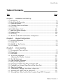
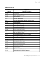
Table of Contents
Title
Page
Chapter 1.
Installation and Start Up
1.1 Introduction........................................................................................................1-1
1.2 Quick Start Up Procedure ...................................................................................1-2
1.3 Unpack the Printer..............................................................................................1-4
1.4 Choosing a Place for the Printer...........................................................................1-5
1.5 Printer Parts .......................................................................................................1-6
1.6 Install the Power Cord ......................................................................................1-11
1.7 Install the Ribbon Cartridge...............................................................................1-13
1.8 Printer Self Test ...............................................................................................1-20
1.9 Interfacing........................................................................................................1-22
1.10 RS-232 and RS-422 Serial Interface Configuration ............................................1-24
Chapter 2.
2.1
2.2
2.3
2.4
Keypad Configuration
Keypad Configuration.........................................................................................2-1
Ready LED........................................................................................................2-2
On/Off Line Key Function...................................................................................2-3
LCD Display......................................................................................................2-6
Chapter 3.
Forms Handling
3.1
3.2
3.3
3.4
Recommended Types and Sizes...........................................................................3-1
Paper Paths ........................................................................................................3-2
Load Forms ........................................................................................................3-3
Top of Form Adjustment ...................................................................................3-13
(Adjusting First Printline Location) ...................................................................3-13
3.5 Tear Off Adjustment .........................................................................................3-15
3.6 Form Thickness Adjustment ..............................................................................3-18
3.7 Heavy Forms Adjustment..................................................................................3-21
3.8 Changing From Main Paper Path to Alternate Path .............................................3-22
3.9 Changing From Alternate Paper Path to Main Paper Path....................................3-24
3.10 Paper Out Condition.........................................................................................3-25
3.11 Automatically Changing Paper Paths on Paper Out............................................3-26
3.12 Selecting Paper Paths Using the Profile Key......................................................3-27
3.13 Selecting Paper Paths From the Host Computer Using DPCL Command .............3-29
Table of Contents i
User’s Guide
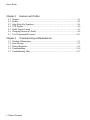
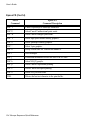
Chapter 4.
4.1
4.2
4.3
4.4
4.5
4.6
4.7
Chapter 5.
5.1
5.2
5.3
5.4
5.5
Features and Profiles
Features.............................................................................................................4-1
Profiles ..............................................................................................................4-2
Setup Mode Key Functions..................................................................................4-4
LCD Display......................................................................................................4-6
Profile Feature Listing.........................................................................................4-7
Changing Features in a Profile .............................................................................4-8
User Programmable Features.............................................................................4-11
Troubleshooting and Maintenance
Scheduled Maintenance ......................................................................................5-1
Error Message ....................................................................................................5-3
Printer Diagnostics .............................................................................................5-8
Troubleshooting................................................................................................5-16
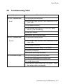
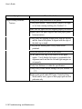
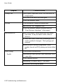
Troubleshooting Table ......................................................................................5-17
ii Table of Contents
User’s Guide
Title
Page
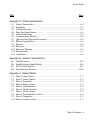
Appendix A. Printer Specifications
A.1
A.2
A.3
A.4
A.5
A.6
A.7
A.8
A.9
A.10
A.11
A.12
A.13
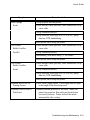
Printer Characteristics.......................................................................................A-1
Emulations .......................................................................................................A-1
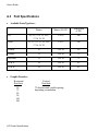
Font Specifications ...........................................................................................A-2
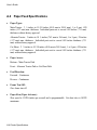
Paper Feed Specifications..................................................................................A-4
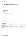
Forms Mode Change.........................................................................................A-5
Communications Interface ................................................................................A-5
Operator Panel Functional Description ...............................................................A-6
Ribbon Cartridge/Drive .....................................................................................A-6
Physical...........................................................................................................A-6
Electrical..........................................................................................................A-7
Shock and Vibration..........................................................................................A-7
Environmental..................................................................................................A-7
Compliances ....................................................................................................A-8
Appendix B. Interface Specifications
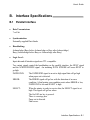
B.1
B.2
B.3
B.4
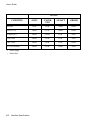
Parallel Interface ..............................................................................................B-1
Parallel Interface Enable/Disable .....................................................................B-6
RS-232 Serial Interface.....................................................................................B-7
Serial Interface Selection................................................................................. B-10
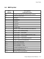
Appendix C. Default Tables
C.1
C.2
C.3
C.4
C.5
C.6
C.7
C.8
C.9
C.10
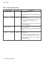
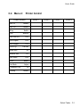
Menu 1: Page Format........................................................................................C-1
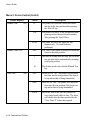
Menu 2: Forms Control.....................................................................................C-2
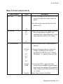
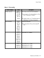
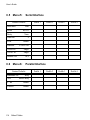
Menu 3: Personality ..........................................................................................C-2
Menu 4: Printer Control.....................................................................................C-3
Menu 5: Serial Interface....................................................................................C-4
Menu 6: Parallel Interface.................................................................................C-4
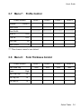
Menu 7: Profile Control.....................................................................................C-5
Menu 8: Form Thickness Control.......................................................................C-5
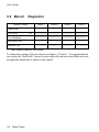
Menu 9: Diagnostics .........................................................................................C-6
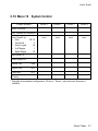
Menu 10 System Control...................................................................................C-7
Table of Contents iii
User’s Guide
Title
Page
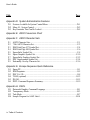
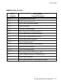
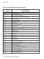
Appendix D. System Administration Features
D.1 Features Available In System Control Menu.......................................................D-1
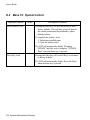
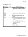
D.2 Menu 10: System Control.................................................................................D-2
D.3 Key Functions That Can Be Locked...................................................................D-5
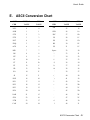
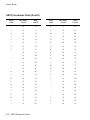
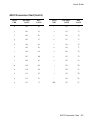
Appendix E. ASCII Conversion Chart
Appendix F. ASCII Character Sets
F.1
F.2
F.3
F.4
F.5
F.6
F.7
F.8
F.9
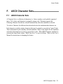
ASCII Character Sets........................................................................................ F-1
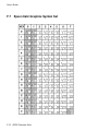
7 Bit ASCII Character Set................................................................................. F-2
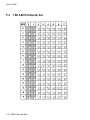
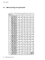
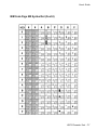
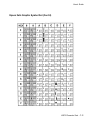
IBM Code Page 437 Symbol Set........................................................................ F-4
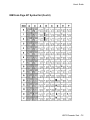
IBM Code Page 850 Symbol Set........................................................................ F-6
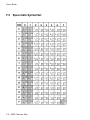
Epson Italic Symbol Set.................................................................................... F-8
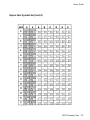
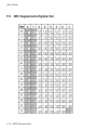
Epson Graphics Symbol Set .............................................................................F-10
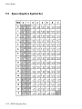
Epson Italic Graphics Symbol Set.....................................................................F-12
DEC Supplemental Symbol Set ........................................................................F-14
Nationality Overlay Character Set ....................................................................F-16
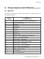
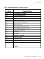
Appendix G. Escape Sequence Quick Reference
G.1
G.2
G.3
G.4
G.5
G.6
Epson FX .........................................................................................................G-1
IBM Proprinter .................................................................................................G-5
DEC LA-120....................................................................................................G-8
TI-885 (optional) ............................................................................................ G-12
DS-180 .......................................................................................................... G-15
DPCL Command Sequence Summary.............................................................. G-19
Appendix H. DGCL
H.1
H.2
H.3
H.4
Datasouth Graphics Command Language ...........................................................H-1
Transparency Mode ..........................................................................................H-3
Task Mode .......................................................................................................H-7
Sample Program for AIAG Label.....................................................................H-10
iv Table of Contents
User’s Guide
1.
Installation and Start Up
1.1
Introduction
This dot matrix impact printer provides high-speed performance, plus a rugged, round-theclock duty cycle, and flexibility to handle a number of printing applications.
Feature Highlights
•
Straight through pin feed paper path for optimum forms handling.
•
Nine wire ballistic printhead and flat metal print platen to assure legibility on every copy.
•
Demand document printing.
•
Automatic Form Thickness adjustment.
•
Forms parking and reloading at the touch of a key.
•
Four user-defined profiles for quick forms set up.
•
Paper path selection by profile.
•
Emulations : Epson FX, DEC LA 120, IBM Graphics, IBM Proprinter XL
•
Options:
a. Second pin feed paper path
b. Cut sheet paper path
c. IBM Coax, IBM Twinax interfaces
d. Quiet cover set
e. Barcodes
f.
Network Interface
Keypad Configuration 1-1
User’s Guide
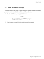
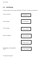
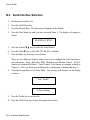
1.2
Quick Start Up Procedure
The following is an abbreviated installation and start up procedure provided for users who are
already familiar with printer products. If you are not experienced with printers, follow all the
instructions in Chapter 1 for setting up the printer.
1.
Place the printer on a suitable stand or countertop.
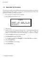
2.
Install ribbon cartridge and power cord.
WARNING
CONNECT 115V
OUTLETS ONLY!
WILL RESULT!
UNITS TO 115V
PRINTER DAMAGE
3.
Turn printer on
4.
Position left tractor with ‘Alignment’ mark on printer. Position front paper guides and
rear paper supports equally across the width of the form. Load 8 ½” paper into
tractors. (For cut sheet forms, set the left cut sheet guide to “0” and insert 8 ½” paper).
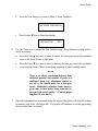
5.
Press the Load Key (unnecessary for cut sheet path).
6.
Open Keypad Door to enter Setup Mode.
7.
Use the Quick Access Key, the Value ▲▼ keys, and the Enter Key to set margins.
8.
Close the Keypad Door.
9.
Press the Profile Key to save settings.
10. Open Keypad Door.
1-2 Keypad Configuration
User’s Guide
CAUTION
IMPROPER MARGIN SETTING CAN
LEAD TO PRINTHEAD DAMAGE! DO
NOT PRINT OFF THE EDGE OF THE
FORM.
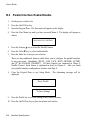
11. Press the Feature ▲ Key. LCD should display “Self Test”.
12. Press the Enter Key.
When the Enter Key is pressed, the self test will begin printing. The self test may be stopped
by closing the Keypad Door or pressing the Enter Key.
Keypad Configuration 1-3
User’s Guide
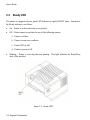
1.3
Unpack the Printer
Remove the following from the shipping carton:
•
Dot Matrix Printer
•
Ribbon Cartridge
•
Power Cord
•
Accessory Kit:
User's Manual
Warranty Card
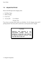
If any items are missing, please contact your distributor. Save the shipping carton and all
packing materials. These items will be needed in the event the printer must be shipped.
CAUTION
SHIPPING THE PRINTER IN ANY
CONTAINER
OTHER
THAN
ITS
ORIGINAL PACKAGING MAY RESULT
IN SHIPPING DAMAGE AND MAY VOID
THE PRINTER WARRANTY.
1-4 Keypad Configuration
User’s Guide
1.4
Choosing a Place for the Printer
The printer weighs approximately 45 pounds. Its dimensions are:
•
17.0 inches (431 mm) wide x 15.7 inches (398 mm) deep x 12.3 (312 mm) inches high
(Dual tractor, top roller versions).
•
17.0 inches (431 mm) wide x 15.7 inches (398 mm) deep x 11.3 inches (287 mm) high
(Standard model).
•
17.0 inches (431 mm) wide x 16.7 inches (424 mm) deep x 12.3 inches (312 mm) high
(Cut Sheet model).
Location
1.
To permit air flow and proper cooling, do not place anything closer than 2 inches
(50mm) to the printer.
2.
Allow 6 inches to the right of the printer for access to the Form Thickness Adjustment
knob.
3.
For continuous printing and accumulation of forms, allow sufficient room behind the
printer for cables and stacking forms.
4.
Place the printer on a sturdy level surface and align lower front edge of printer with
table edge.
5.
Locate the printer near a grounded power receptacle and use the power cord provided.
Do not use an extension cord to connect the printer.
6.
Avoid the following:
•
•
•
•
•
•
Direct sunlight or excessively illuminated areas
Direct placement in front of air conditioning or heating vents
Extreme high or low temperatures
Exposure to excessive dirt or dust
Exposure to vibration or mechanical shock
Excessive humidity or condensation
Keypad Configuration 1-5
User’s Guide
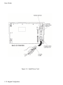
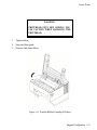
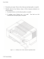
1.5
Printer Parts
Four basic models of the printer are available:
•
Standard straight tractor paper path with standard access cover.
•
Straight tractor paper path with top roller set and sound reduction access cover.
•
Dual tractor path (straight and 45 °) with top roller set and sound reduction access cover.
•
Straight tractor path and cut sheet (Friction Feed) path with top roller set and sound
reduction access cover.
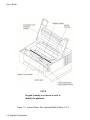
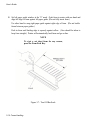
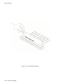
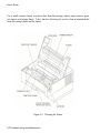
Use the following illustrations to locate the major printer parts for each model. The standard
model is used to illustrate most of the procedures in this manual.
Figure 1-1: External Printer Parts (Standard Model) (Sheet 1 of 2)
1-6 Keypad Configuration
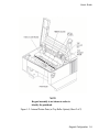
User’s Guide
Figure 1-1: External Printer Parts (Dual Path and Sound Reduction Access Cover)
(Sheet 2 of 2)
Keypad Configuration 1-7
User’s Guide
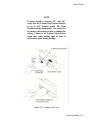
NOTE
Keypad assembly is not shown in order to
identify the printhead.
Figure 1-2: Internal Printer Parts (Standard Model) (Sheet 1 of 2)
1-8 Keypad Configuration
User’s Guide
NOTE
Keypad assembly is not shown in order to
identify the printhead.
Figure 1-2: Internal Printer Parts (w/Top Roller Option) (Sheet 2 of 2)
Keypad Configuration 1-9
User’s Guide
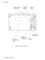
Figure 1-3: Back Printer Parts
1-10 Keypad Configuration
User’s Guide
1.6
Install the Power Cord
1.
Set the power switch to Off. (See Figure 1-4).
2.
Install the power cord into the printer as shown in Figure 1-4.
3.
Verify that voltage setting is correct for the application (115V-U.S.) (See Figure 1-4).
WARNING
CONNECTING THIS EQUIPMENT TO AN
UNGROUNDED POWER RECEPTACLE
CAN RESULT IN ELECTRICAL SHOCK.
4.
Install the plug end of the power cord into a grounded AC outlet. The voltage of the
AC power receptacle must match the voltage rating on the power cord receptacle label.
A grounded outlet must be used. Plugging the printer into an ungrounded outlet may
result in increased radio frequency noise generation, erratic printer operation, or
electrical shock.
5.
Set the power switch to ON. The alarm will sound 3 short tones and the printer will
display:
Paper Out: Main
Keypad Configuration 1-11
User’s Guide
Figure 1-4: Install Power Cord
1-12 Keypad Configuration
User’s Guide
1.7
Install the Ribbon Cartridge
To prolong ribbon life, the printer is shipped without the cartridge installed. The following
procedure is written for both initial installation and ribbon replacement.
1.
Press the On/Off Line key to display "off line" status.
NOTE
If paper is loaded, press PARK key to park
the form in the tractors.
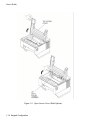
2.
Open top access cover and lift roller assembly on models so equipped.
Keypad Configuration 1-13
User’s Guide
Figure 1-5: Open Access Cover (Both Options)
1-14 Keypad Configuration
User’s Guide
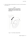
3.
Check the Form Thickness Adjustment Knob to be sure that it is in the first position as
shown in Figure 1-6.
NOTE
If replacing the ribbon, the Form Thickness
Adjustment Knob will automatically move
away from the form when the paper is parked
in the tractors.
Figure 1-6: Form Thickness Adjustment Knob
Keypad Configuration 1-15
User’s Guide
NOTE
Steps 4 and 5 are not required for initial
ribbon installation.
4.
Remove the ribbon guide from printhead (lift up and rotate towards front).
5.
Remove ribbon cartridge from printer.
6.
Figure 1-7: Remove Ribbon Guide
Move the printhead to the center of the printer.
1-16 Keypad Configuration
User’s Guide
WARNING
PRINTHEAD GETS HOT DURING USE.
USE CAUTION WHEN HANDLING THE
PRINTHEAD.
7.
Tighten ribbon.
8.
Snap on ribbon guide.
9.
Remove slack from ribbon.
Figure 1-8: Position Ribbon Cartridge In Printer
Keypad Configuration 1-17
User’s Guide
10. Lower ribbon cartridge towards slots in printer. Ensure that ribbon loop is in front of
platen and that ribbon is not twisted.
11. Drop the ribbon cartridge into the ribbon alignment slots.
12. If the ribbon cartridge does not seat squarely on the ribbon drive, rotate the Ribbon
Advance Knob in the direction indicated by the arrow on the knob until the cartridge
drops into place on the ribbon drive. See Figure 1-9.
13. With ribbon guide tilted to front of printer, place the guide on printhead nose. Push
down on ribbon guide until it snaps into place.
14. Remove any slack from the ribbon by turning the Ribbon Advance Knob in the
direction of the arrow marked on the knob.
1-18 Keypad Configuration
User’s Guide
Figure 1-9: Install Ribbon Cartridge
Keypad Configuration 1-19
User’s Guide
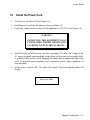
1.8
Printer Self Test
This test is used to verify printer operation. Before performing the printer self-test, refer to
Section 3.3 Load Forms Page 3-3 for instructions on loading paper in the printer.
To start the test:
CAUTION
MARGINS ARE SET FOR 8.5” PAPER.
PRINTING OFF OF FORM WILL LEAD
TO PRINTER DAMAGE.
1.
Load 8-1/2" forms.
2.
Open the Keypad Door.
3.
Press the Feature ▲ Key once. LCD will show "RUN SELF TEST".
4.
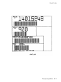
Press the Enter Key. Printer self test will start (Figure 1-10). The display will
alternate between the following:
<Diagnostics>
‘Enter’ To Stop
5.
The self-test may be stopped by pressing the Enter key or by closing the Keypad
Door.
1-20 Keypad Configuration
User’s Guide
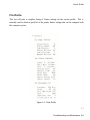
Figure 1-10: Self-Test Sample
Keypad Configuration 1-21
User’s Guide
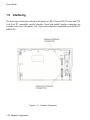
1.9
Interfacing
The three types of interfaces offered by the printer are RS-232 serial, RS-422 serial, and TTL
level 8-bit PC compatible, parallel interface. Serial and parallel interface connectors are
provided on the rear of the printer. The 25-pin serial connector is compatible for both RS-232
and RS-422.
Figure 1-11: Interface Connectors
1-22 Keypad Configuration
User’s Guide
Refer to the documentation for your computer to determine the type of shielded interface
cable needed and any unique pin-out configuration that may be required. This information
should be given to your dealer or distributor to determine the correct cable for your use.
WARNING
BEFORE CONNECTING THE CABLE,
MAKE CERTAIN BOTH THE HOST
COMPUTER AND THE PRINTER ARE
POWERED OFF.
Attach one end of the cable to the proper connector on the printer and the other end to the
host computer. Secure the interface cable to the connector with the screws or wire clips
provided.
Keypad Configuration 1-23
User’s Guide
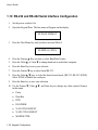
1.10 RS-232 and RS-422 Serial Interface Configuration
1.
Set the power switch to On.
2.
Open the Keypad Door. The first menu will appear on the display.
M1 PAGE FORMAT
3.
Press the Next Menu key until you have accessed Menu 5
M5 SERIAL CNTRL
4.
Press the Feature ▲ Key one time to select Baud Rate Feature.
5.
Press the Value ▲ or Value ▼ to change baud rate to match host computer.
6.
Press the Enter Key to save your selection.
7.
Press the Feature ▼ key to select Serial RS-232.
8.
Press the Value ▲ ▼ keys to select the desired serial mode [RS-232, RS-422, NONE].
Select NONE to disable the serial port.
9.
Press the Enter key to save your selection.
10. Use the Feature ▼, Value ▲ ▼, and Enter keys to change any other required features
in this menu.
•
Parity
•
Data Bits
•
DTR
•
HANDSHK
•
X-ON CTRL ROBUST
•
X-OFF CTRL ROBUST
•
MODEM CTRL
1-24 Keypad Configuration
User’s Guide
11. Close the Keypad Door to exit Setup Mode. Display will alternate:
Press ‘Profile’
To Save Settings
12. Press the Profile key to permanently save the profile setting.
13. Press the On/Off Line Key to place the printer back on line.
On Line Profile 1
Keypad Configuration 1-25
User’s Guide
1-26 Keypad Configuration
User’s Guide
2.
Keypad Configuration
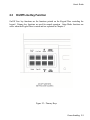
2.1
Keypad Configuration
This chapter describes the keypad, Ready LED, and LCD display. The locations of all keys
and their functions are illustrated below.
Figure 2-1: Keypad Configuration
Forms Handling 2-1
User’s Guide
2.2
Ready LED
The printer is equipped with one green LED indicator to signify READY status. Function of
the Ready indicator is as follows:
•
On – Printer is on line and ready to accept data.
•
Off – Printer cannot accept data for any of the following reasons:
a. Printer is off line.
b. Printer is in an error condition.
c. Printer FIFO is full.
d. Printer is powered off.
•
Blinking – Printer is receiving data and printing. This light indicates the Ready/Busy
state of the interface.
Figure 2-2: Ready LED
2-2 Keypad Configuration
User’s Guide
2.3
On/Off Line Key Function
On/Off Line key functions are the functions printed on the Keypad Door encircling the
keypad. Primary key functions are used for normal operation. Setup Mode functions are
active when the Keypad Door is raised and are explained in Chapter 4.
Figure 2-3: Primary Keys
Forms Handling 2-3
User’s Guide
Pressing this key switches the printer between on line and off line status.
This key is used in conjunction with the LCD display. The On/Off Line key
is also used to continue after clearing an error condition or to acknowledge
tearing off a form on a paper path change.
Pressing this key will load paper into the main or alternate feed paths when
paper is not already loaded.
When continuous forms are loaded, pressing this key advances the paper to
the top of the next form.
When paper is loaded, pressing the Park/Path key ‘parks’ paper into the
tractors.
When paper is not loaded and the printer is off line, pressing the Park/Path
key changes the paper path and attempts to load paper (on dual path units).
Either Main or Alternate paper path can be selected using this key.
The Path key is only valid if the Path feature is set to “Either”. Paper paths
can also be selected by setting the path feature in a profile and selecting that
profile. For additional instructions, see 3.8 – 3.13.
Pressing this key moves the form upward 1/144 inch for precise form
alignment. When the key is pressed for more than ½ second, the paper
advances continuously until the key is released.
2-4 Keypad Configuration
User’s Guide
Pressing this key moves the form downward 1/144 inch for precise form
alignment. When the key is pressed for more than ½ second, the paper
reverse feeds continuously until the key is released.
Pressing this key advances forms up to the tear bar so that the last printed
form can easily be removed. Pressing the key a second time moves the form
back into print position.
To change the tear off position, press the Tear Off key, press Adjust ▲ or ▼,
and press the Tear Off key again. The new distance will be automatically
saved in the current profile.
Pressing this key once advances the paper by one line. When the key is
pressed for more than ½ second, continuous line feeds are performed until the
key is released.
This key allows you to select one of four user-defined profiles. To use this
key, place the printer off line; then press the Profile key. Available profile
names will be shown in the display window each time the Profile key is
pressed. This key can be used only when the printer is off line. For more
information about profiles see Chapter 4.
After changing profiles, the user should park and reload the paper to reset
top-of-form. The printer will automatically change paper paths or request a
form to be loaded depending on the Path feature setting. See Section 3.12 for
details on selecting paper paths using the Profile key.
Forms Handling 2-5
User’s Guide
2.4
LCD Display
The printer signals various messages through the LCD display. Examples are shown below:
Features and Values:
Left Margin xxx
On Line Display:
Off Line Display:
Paper Out Conditions:
On Line Profile 1
Off Line Profile 1
<Paper Out Main>
<Paper Out Alt>
Initial Display when Keypad Door
is open:
2-6 Keypad Configuration
M1 PAGE FORMAT
User’s Guide
3.
Forms Handling
3.1
Recommended Types and Sizes
The following are guidelines for recommended paper types and sizes for use with the printer.
Continuous Forms (Main Paper Path)
Width – 3 ½ to 10 5/8 inches (88.9mm to 269.8 mm)
Individual Part Thickness - .005 inch maximum (.127mm)
Total Form Thickness - .028 inch maximum (.711mm)
Number of copies – 1 original plus 8 copies
Maximum Printable Width – 8.8 inches (223 mm)
Continuous Forms (Alternate Paper Path)
Width – 3 to 10 ½ inches (76.2 mm to 266 mm)
Individual Part Thickness - .005 inch maximum (.127 mm)
Total Form Thickness - .028 inch maximum (.711 mm)
Number of copies – 1 original plus 8 copies
Maximum Printable Width – 8.8 inches (223 mm)
Cut Sheet Forms (Cut Sheet Path)
Width – 2 ¾ to 10 5/8 inches (69.9 mm to 269.8 mm)
Individual Part Thickness - .005 inch maximum (.127 mm)
Total Form Thickness - .028 inch maximum (.711 mm)
Number of copies – 1 original plus 8 copies
Maximum Printable Width – 8.8 inches (223 mm)
Minimum Form Length – 4.25 inches (110 mm)
Minimum Form Weight – 20 lb. Bond (75 g/m2 )
Forms Handling 3-1
User’s Guide
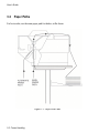
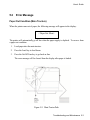
3.2
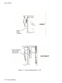
Paper Paths
For best results, use the main paper path for thicker, stiffer forms.
Figure 3-1: Paper Feed Paths
3-2 Forms Handling
User’s Guide
3.3
Load Forms
NOTE
To load the main tractor path on Dual Path
printer, place alternate path tractors in
center position. Main tractor doors cannot be
opened with alternate tractors aligned in
front. (Hint: Use least frequently changed
paper in main tractors and frequently
changed paper or narrow stock in the
alternate path.) If both paths are used, main
tractor path must be loaded first.
NOTE
If paper is to be loaded into alternate path,
align the left tractors with alignment mark on
printer for both feed paths before loading
front most forms.
NOTE
Form
Thickness
Adjustment
Knob
automatically retracts printhead to allow for
forms loading and repositions to print
position after loading.
To access the tractors and load a continuous form into either tractor, proceed as follows: (For
cut sheet forms, go directly to Step 8.)
1.
Unlock both tractors by rotating the locking levers.
2.
Align the left tractor with the alignment mark located on the body of the printer. Lock
left tractor in place. Place the right tractor at the approximate forms width.
Forms Handling 3-3
User’s Guide
CAUTION
IMPROPER
TRACTOR
LOCATION
RESULTING IN PRINTING PAST THE
EDGE OF THE FORM CAN CAUSE
DAMAGE TO THE PRINTHEAD.
3.
Position the front paper guides and rear paper supports equally across width of form.
(Hint: For easy movement, grab the front paper guides and push up while sliding.)
NOTE
Proper position of paper supports will help
prevent jams.
4.
Open the left tractor door and place the left side of the form in the left tractor. Close
tractor door. (Hint: Place form on lower 3 pins of tractor drive. Hold form in place by
pressing against tractor housing before closing tractor door with other hand.)
Figure 3-2: Load Paper In Tractors (Typical)
3-4 Forms Handling
User’s Guide
5.
Open the right tractor door and load the paper into the right tractor. Compare position
of paper in left and right tractors and adjust as necessary to keep paper even. Improper
alignment of paper feed holes (Figure 3-3) will result in paper jam. Close tractor door.
6.
If necessary, move the right tractor to the right to slightly tension the paper. Lock the
tractor in this position.
CAUTION
IMPROPER PAPER TENSION MAY
CAUSE PAPER JAMS. PAPER SHOULD
BE TENSIONED SUFFICIENTLY TO BE
RELATIVELY FLAT BETWEEN THE
TRACTORS,
WHILE
AVOIDING
DISTORTION OF THE PAPER FEED
HOLES.
Forms Handling 3-5
User’s Guide
Figure 3-3: Forms Loading (Sheet 1 of 2)
3-6 Forms Handling
User’s Guide
Figure 3-3: Forms Loading (Sheet 2 of 2)
Forms Handling 3-7
User’s Guide
7.
Make sure the continuous forms are located directly under the tractors. The paper must
hang straight. Incorrect positioning of the forms may cause a paper jam.
Figure 3-4: Placement of Continuous Forms
3-8 Forms Handling
User’s Guide
8.
Set the power switch to On. (For cut sheet forms, go directly to Step 10).
Figure 3-5: Turn On Power
9.
After the printer initializes, press the Load key to load paper. When the load key is
pressed, the Form Thickness Adjustment knob will automatically move to the correct
location. Go to Step 11.
Figure 3-6: Press Load Key
Forms Handling 3-9
User’s Guide
10. Set left paper guide window at the “0” mark. Grab form in center with one hand and
align left edge of form against left paper guide. (Do not fully insert form.)
Use other hand to snug right paper guide against right edge of form. (Do not buckle
forms between paper guides.)
Push in form until leading edge is squarely against rollers. (Care should be taken to
keep form straight.) Printer will automatically load form and go on line.
NOTE
To eject a cut sheet form for any reason,
press the Form Feed Key.
Figure 3-7: Tear Off Bar Scale
3-10 Forms Handling
User’s Guide
NOTE
If forms length is between 4.5” and 6.0”,
verify that the Vertical Gap Position Feature
is set to 0.0” (located under M8 Form
Thickness in the setup mode). See Section 4.6
for further instructions on how to change this
setting. Failure to set Vertical Gap for these
forms may cause trailing edge of form to
catch under guide during loading.
Figure 3-8: Loading Cut Form
Forms Handling 3-11
User’s Guide
11. Set form length, right and left margins. To set form length, first measure the length of
the form (in inches) and multiply this value by the vertical lines per inch. For
example: if the form length is 11 inches and the vertical pitch is 6 lines per inch, then
the form length would be:
11 inches x 6 lines per inch = form length 66 lines
To set the form length, open the keypad door and press the Quick Access key until
“Form Length” appears in the display. Press the Value keys to change the setting and
press the Enter key to save the setting.
To set left and right margins, measure the printed width of the form (in inches
excluding pinfeed holes) and multiply this value by the font pitch. The scale on the
tear off bar may be used to estimate margin location for 10 cpi.
For example: if the printed form width is 8.5 inches and the font pitch is 10 characters
per inch, then the form width would be:
8.5 inches by 10 cpi = right margin 85
To set the right margin, press the Quick Access key until “Right Margin” appears in
the display. Press the Value keys to change the margin setting and press the Enter keys
to save the setting. If you shift the left margin, you may want to shift the right margin
by the same amount. Close the keypad door to exit Setup Mode. The LCD will read:
Press Profile
To Save Settings
12. Press Profile key to save settings.
13. Place the On/Off Line key to place the printer back on line.
3-12 Forms Handling
User’s Guide
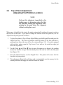
3.4
Top of Form Adjustment
(Adjusting First Printline Location)
NOTE
Perform this adjustment immediately after
loading paper to determine where the first
line will print. Making this adjustment while
printing on the page allows fine alignment
without resetting line count.
When paper is loaded into the printer, the printer automatically positions the paper to print on
the first line of the form. If you need to change the location of the first print line, use the
Adjust Form key and proceed as follows:
1.
To place the printer in Top-of-Form Adjust Mode, open the Keypad Door and press the
Adjust Form key. The form will advance until the bottom of the first print line is
positioned just above the tear off bar for viewing (Figure 3-9). (For units equipped
with cut sheet option, open the Top Access Cover and use the metal tear edge just
above the top rollers.)
2.
Use the Value ▲ and Value ▼ keys to move the paper up or down to the position
desired for first line of type. The line directly above the tear bar will be the first print
line (Figure 3-9).
3.
Press the Adjust Form key or close Keypad Door. The printer will reverse feed the
form back to print position.
4.
This adjustment affects the Load feature and is automatically saved in memory for the
current profile and will apply the next time forms are loaded.
Forms Handling 3-13
User’s Guide
Figure 3-9: Set First Print Line
3-14 Forms Handling
User’s Guide
3.5
Tear Off Adjustment
In a demand document application, the form will be advanced to a tear off position when the
Tear Off key is pressed. When the forms are in this position, the last printed form may be
removed by pulling the perforation against the tear edge of the cover.
If the perforation does not come to rest at the tear edge, the tear off distance may be adjusted
as follows:
1.
Press the Tear Off key. The form should move up to the current tear location.
NOTE
By adjusting the tear distance to a large
value, the form can be fed through a
countertop, for example, if the printer is
located under a counter.
2.
Using the Adjust ▲ key or the Adjust ▼ key, move the paper until the perforation is
located at the desired tear off position.
3.
Press the Tear Off key. The form will return to the current print position.
4.
This adjustment affects the Tear Distance feature and is automatically saved in
memory for the current profile and will be applied when forms are reloaded.
Forms Handling 3-15
User’s Guide
NOTE
For cut sheet units, to avoid excessive opening
and closing of the Top Exit Cover when
alternating between short cut sheet forms and
continuous tractor forms, adjust the tear bar
(metal edge located immediately above top
rollers) by using this procedure. (The value
will be about 1-40/144 inches.)
NOTE
The function of the Tear Off key is affected
by the Manual Tear feature located in the
Forms Control Menu. Refer to Chapter 4 for
a description of this feature.
3-16 Forms Handling
User’s Guide
Figure 3-10: Printer Located Under Countertop
Forms Handling 3-17
User’s Guide
3.6
Form Thickness Adjustment
The distance from the printhead to the paper is automatically changed to accommodate the
thickness of the forms whenever the unit is powered up or paper is loaded. The adjustment
can be manually changed using the knob on the right-hand side of the printer, or adjusted
automatically by changing the feature setting as outlined below:
CAUTION
IMPROPER
ADJUSTMENT
PRINTHEAD.
FORM
THICKNESS
CAN DAMAGE THE
1.
Load the form requiring this adjustment and run a print sample.
2.
Inspect the print sample. The characters should be easily read with no missing dots.
Be sure to check the last copy of multi-part forms for properly formed characters.
NOTE
To adjust form thickness automatically and
store in memory, proceed with Step 3. If a
temporary adjustment is needed, adjust
manually beginning with Step 7.
3.
If the print quality is unacceptable (too tight, missing dots, or smearing), or paper
handling is affected, adjust form thickness gap as follows:
a. Open the Keypad Door to access Setup menu.
3-18 Forms Handling
User’s Guide
b.
Press the Next Menu key to access Menu 8, Form Thickness.
M8 FORM THICKNESS
c.
Press Feature ▼ key to obtain this display.
Adj Form Gap
4.
XX
Use the Value keys to adjust the form thickness gap. Form thickness setting will be
stored in memory.
a. Press the Value ▲ key once or twice to reduce the form gap (moves the printhead
closer to the form) if there is light print.
b.
Press the Value ▼ key once or twice to increase the form gap (moves the printhead
away from the form) if there is smudging, smearing or paper handling issues.
NOTE
There is no direct correlation between form
thickness position and number of parts in a
multi-part form (e.g. adjustment control is
not set to the fourth mark for a four-part
form). Multi-part carbonless forms must be
given time to cure before being separated to
prevent light print quality. (Contact paper
supplier for cure times.)
5.
Once the adjustment has been made using the keypad, the printer will store the setting
in memory only in the selected profile. The printer will continue to use this gap setting
the next time forms are loaded.
Forms Handling 3-19
User’s Guide
6.
Run another print sample. Return to Step 2 and repeat until print quality is acceptable.
7.
Manually adjust the form thickness setting as follows (temporary adjustment, not
stored in memory):
a. Turn knob clockwise one click until print quality is acceptable.
b. If smudging occurs, thickness gap is too small.
counterclockwise until print quality is acceptable.
Turn knob one click
Figure 3-11: Manually Move Form Thickness Adjustment Knob
3-20 Forms Handling
User’s Guide
3.7
Heavy Forms Adjustment
The Heavy Forms feature allows the printhead to be positioned horizontally on the form to
avoid labels, paper perforations or other variations in form thickness that can cause paper
handling issues.
This feature becomes active when the paper moves more than 0.5 inches.
The default location of the printhead is 2 inches from the left side of the printer.
To change the location of the printhead from the default value, follow these steps:
1.
Load form in printer and open Keypad Door.
2.
Press Menu key to access M2 Forms Control.
3.
Press Feature ▼ key to access the Heavy Forms feature.
4.
The value in the display represents the location of the printhead for form feeds and
paper advances over 0.5”.
5.
Press the Value keys to change this setting.
For example: A label is located on the form from 3 to 5 inches from the left edge of the
form. Set the Heavy Form feature at 1.5 inches or 6.5 inches to insure that the
printhead and ribbon guide is away from the label during high speed paper moves. The
feature may also be set to avoid paper staples on the pin drive margins of the forms.
If the entire form is jamming, set this value to 9.8 inches to keep the printhead from the
perforation folds (paper tents) during form feeding.
Forms Handling 3-21
User’s Guide
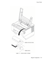
3.8
Changing From Main Paper Path to Alternate Path
If continuous forms are presently loaded in the printer, you may change to the alternate paper
path by proceeding as follows:
(For cut sheet models, just insert the form.
executed by the printer.)
The following steps will be automatically
1.
Press the On/Off Line key to take printer off line.
2.
Press the Tear Off key to advance the form to the tear off point.
3.
Remove the last printed form.
4.
Press the Park key. The continuous forms will be backed down out of the paper path
and held in the forms tractors. The display will appear as shown:
< Paper Out Main >
5.
Press the Path key. The printer will shift to the alternate path then attempt to load
paper.
6.
If paper is not loaded in the alternate path, the display will indicate so.
< Paper Out Alt >
7.
If paper is loaded, press On/Off Line key.
NOTE
To use the Path key, the ‘Path’ feature setting
must be set to ‘Either’ in the current selected
Profile. If the ‘Path’ feature is set to ‘Main’
or ‘Alt’, the Path key is disabled. See
Sections 3.12 – 3.13 for a description of paper
path changing using Profiles.
3-22 Forms Handling
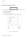
User’s Guide
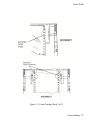
Figure 3-12: Main and Alternate Paper Paths
(Cut Sheet not Shown)
Forms Handling 3-23
User’s Guide
3.9
Changing From Alternate Paper Path to Main
Paper Path
If paper is loaded in the alternate printer path, you may change to the Main Paper Path by
proceeding as follows:
1.
Press the On/Off Line key to take printer off line.
2.
Press the Tear Off key to advance form to tear off point. Remove last printed form.
3.
Press the Park key. The continuous forms will be backed down out of the paper path
and held in the tractors. The display will appear as shown:
<Paper Out: Alt>
4.
Press the Path key. The printer will shift to the Main Paper Path and automatically
load paper. If paper is not loaded in the main path, the display will indicate so.
<Paper Out: Main>
5.
If paper is loaded, press On/Off Line key.
NOTE
To use the Path key, the ‘Path’ feature setting
must be set to ‘Either’ in the current selected
Profile. If the ‘Path’ feature is set to ‘Main’
or ‘Alt’, the Path key is disabled. See
Sections 3.12 – 3.13 for a description of paper
path changing using Profiles.
3-24 Forms Handling
User’s Guide
3.10 Paper Out Condition
When the printer runs out of paper, the following messages will appear in the display
depending on paper path selected:
<Paper Out: Main>
<LOAD CHECKS>
or
<Paper Out: Alt>
<LOAD PROFILE 2>
1.
Remove last printed form from paper path by using Form Feed key.
2.
Load continuous forms. Refer to Page 3-3.
3.
Press the On/Off Line key to go back on line.
The alternating display indicates which path (Main, Alt) is empty and which form to reload.
NOTE
If the Profile has not been renamed to match
the form being used, the display will indicate
‘Load Profile x’ as shown in the example
above. In this case, the form associated with
Profile 2 should be loaded.
For more
information on naming Profiles, see the
‘Rename’ feature located in the Profile
Control menu described in Chapter 4.
Forms Handling 3-25
User’s Guide
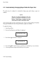
3.11 Automatically Changing Paper Paths On Paper Out
The printer may be configured to automatically change paper paths during a paper out
condition.
NOTE
This may be useful in applications where the
printer is unattended or installed at a remote
location. If this feature is enabled, the same
forms must be loaded in both paper paths.
After changing paths, the printer will attempt a load. If paper is found, printing will continue.
If no paper is installed, the unit will stop and indicate a paper out condition.
To enable this feature:
1.
Open Keypad Door.
2.
Press the Next Menu key until Menu 4 is displayed.
M4 PRINTER CNTRL
3.
Press Feature ▲ until feature is displayed.
Auto Path SW Off
4.
Press Value ▲ ▼ to turn the feature on, and then press the Enter key to save selection.
5.
Close Keypad Door and press the Profile key to save profile.
3-26 Forms Handling
User’s Guide
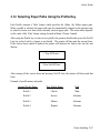
3.12 Selecting Paper Paths Using the Profile Key
Each Profile contains a ‘Path’ feature which specifies the (Main, Alt, Either) paper path.
When a profile is selected, the paper path may be automatically changed or the operator may
be asked to load a new form in the currently selected paper path. The action taken depends
on the value of the ‘Path’ feature setting (located in Menu 2 Forms Control).
After using the Profile key to select a new profile, the operator should either press the On/Off
Line key or the Load key if paper is not loaded. The printer will then park the current form.
If the current form cannot be parked, the printer will advance the form to the tear bar and
display:
< Tear Off Form >
< Press On/Off Line >
After tearing off the current form and pressing On/Off Line, the printer will then park that
form.
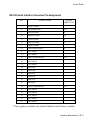
Example of profile names and paths:
Original Profile Name
New Profile Name
Path
Profile 1
Checks
Main
Profile 2
Invoice
Alternate
Profile 3
Memos
Alternate
Profile 4
Reports
Alternate
Forms Handling 3-27
User’s Guide
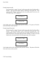
Example using same path:
The current profile is named “Invoices” and the paper path selected by that profile is
alternate. The new profile named “Memos” specifies the same path (Alt). After
selecting profile “Memos” and the printer has successfully parked the invoices, the
following message will be displayed:
< Load Memos in >
< Alt Paper Path >
After loading memos into the alternate path, press the Load key. The printer will load the
memos and resume normal operation.
Example using different path:
The current profile is named “Invoices” and the paper path selected by that profile is
alternate. The new profile named “Checks” specifies the main paper path. After
selecting profile “Checks” and the printer has successfully parked the invoices, the
printer will load the main paper path and resume operation. If there is no form
loaded in the selected path (main), the following message will be displayed:
< Paper Out: Main >
< Load Checks >
After loading checks into the main paper path, press the Load key. The printer will load the
checks and resume normal operation.
3-28 Forms Handling
User’s Guide
3.13 Selecting Paper Paths From the Host
Computer Using DPCL Command
In demand document applications, the paper path may be selected by using Downline Printer
Control Language (DPCL) sequences to select the active Profile 1-4. This command is
available in all emulation modes. Indicating a profile using DPCL commands will allow
paper path selection from the host computer. For more information on configuring features
and profiles, see Chapter 4.
NOTE
In dual tractor units, the most frequently
used form should be loaded in the main path
and other forms in the alternate path. Now,
changing profiles will prompt the operator to
load the correct form in the alternate path.
To ensure the correct form is loaded, the
alternate path should be left empty when not
in use. This will cause the printer to stop and
indicate which form to load when the path is
selected.
After the profile is configured, it may be selected for the host computer using DPCL
sequences. The paper path will be selected according to the profile selection. Refer to
previous Section 3.12 for further information on paper path selection using profiles.
Forms Handling 3-29
User’s Guide
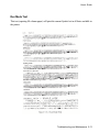
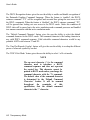
The DPCL sequence to change profiles is active in all emulations.
Select Profile (form) <n>
CODE
FORMAT
ASCII: ESC
DECIMAL:
HEXADECIMAL:
ESC$$E1.I18;<n>.X.
$
$
E
1
.
I
1
8
;
<n>
.
X
.
27
36
36
69
49 46 73 49
56
59
n
46
88
46
1B
24
24
45
31 2E 49 31
38 3B
n
2E 58 2E
Description:
This command is used to select Profile n where values of n range from 1 to 4.
The Paper Path may be selected by the Host Computer by configuring the
‘Path’ feature to Main, Alt, or Either, and by selecting the Profile using this
sequence.
Example:
10 rem select Profile 2
20 print chr$(27);”$$E1.I18;2.X.”
Comment:
See Chapter 4 for a description of Profile features including the ‘Path’
feature.
* Only the Main selection is available on single path units.
3-30 Forms Handling
User’s Guide
4.
Features and Profiles
4.1
Features
This chapter describes and explains the various user programmable features of the printer.
Using the keypad, the printer can be easily configured to operate in a variety of host
environments and provide print for common applications such as reports, checks, invoices,
and labels.
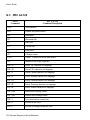
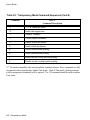
The printer’s features are grouped into the following 10 categories:
Menu Name
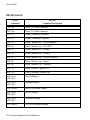
Feature Examples
M1 PAGE FORMAT
Line/Inch, Form Length, Margins, etc.
M2 FORMS CONTROL
Load Dst, Horz Adj., etc.
M3 PERSONALITY
Emulations , Fonts, Character Sets, etc.
M4 PRINTER CONTROL
Auto LF, Auto CR, etc.
M5 SERIAL CONTROL
Baud Rate, Parity, Handshaking, etc.
M6 PARALLEL CONTROL
Handshaking, Ack After Busy, etc.
M7 PROFILE CONTROL
Naming, Saving Profiles, etc.
M8 FORM THICKNESS
Auto Form Gap, Retract Printhead, adjust Form Gap, etc.
M9 DIAGNOSTICS
Print Profile , Print Test, Firmware Rev., etc.
NOTE
System Control Group must be activated for
access. See Appendix D.
M10 SYSTEM CONTROL
Off Line, Reset Key Lock, Quick Access, etc.
See Pages 4-11 through 4-26 for a detailed listing and description of all features and values.
Features and Profiles 4-1
User’s Guide
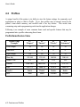
4.2
Profiles
A unique benefit of this printer is its ability to store the feature settings for commonly used
applications in what is called a Profile. Up to four profiles may be named, stored in the
printer’s non-volatile memory, and recalled with a few key strokes. This avoids time
consuming setup and reprogramming each time the application changes.
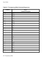
Following is an example of some common forms used and specific features that may be
programmed into a profile when using these forms:
Profile Name/Feature Value
Feature Name
“Example”
P1
“Report”
P2
“Invoice”
P3
“Checks”
P4
“Statements”
Form Length
88
66
24
30
Lines/Inch
8
6
6
6
136
80
70
70
135/144
135/144
100/144
200/144
FF
TOF
TOF
TOF
IBM PRO
IBM PRO
LA 120
LA 120
Font
DP 17.1
Draft 10
OCR A
Draft 10
Parallel
Enable
Disable
Disable
Enable
Main
Either
Alternate
Alternate
Right Margin
Horz Adj
Manual Tear
Emulate
Path
4-2 Features and Profiles
User’s Guide
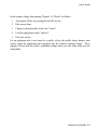
In this sample, change from printing “Reports” to “Checks” as follows:
1.
Take printer off line by pressing the On/Off Line key.
2.
Park current form.
3.
Change to desired profile, in this case “checks”.
4.
Load the appropriate forms (“checks”).
5.
Place unit on line.
For an application that is not stored in a profile, call up the profile whose features most
closely match the application and reprogram only the features requiring change. These
changes will not alter the profile’s permanent settings unless you save them when you exit
Setup Mode.
Features and Profiles 4-3
User’s Guide
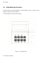
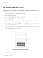
4.3
Setup Mode Key Functions
To change features, open the Keypad Door to enter Setup Mode. Figure 4-1 shows the Setup
Mode keys and their respective functions.
A brief description of each key function follows:
Figure 4-1: Setup Mode Keys
4-4 Features and Profiles
User’s Guide
The Next Menu key provides access to a specific group of features. Pressing
this key steps through the printer features by menu. This prevents having to
“cycle through” the entire list using the Feature key in order to get to the
desired feature.
This key provides immediate access to typical features required for quick
setup. These include font, margins, form length, and lines/inch. The features
accessed by this key can be changed to correspond to the user’s needs.
The Feature keys are used to select a specific feature. Press the Feature ▲
key will move the display up the features list. Pressing the Feature ▼ key
will move the display down the features list. When a menu boundary is
crossed in either direction, it will be displayed.
The Value keys are used to change the value of a feature. Pressing the
Value ▲ key increases feature values. Pressing the Value ▼ key decreases
feature values.
The Enter key is used to accept new values for printer features. After the
value of a feature has been changed, the Enter key is pressed to save the new
settings into memory.
This key enables the user to adjust the top-of-form setting (first printline
location) using the Value ▲ ▼ keys.
Features and Profiles 4-5
User’s Guide
4.4
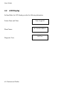
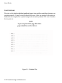
LCD Display
In Setup Mode, the LCD display provides the following information:
Feature Name and Value:
Menu Names:
Diagnostic Tests:
4-6 Features and Profiles
Form Length 88
M1 PAGE FORMAT
Self Test
User’s Guide
4.5
Profile Feature Listing
To print a listing of the feature settings of a particular profile, follow the steps below:
1.
Make certain 20 column or wider paper is loaded in the printer.
2.
Press the On/Off Line key to take the printer off line.
3.
Before entering Setup Mode, press the Profile key until it displays the profile you wish
to print.
4.
Open the Keypad Door and use the Next Menu key to go to Menu 9. The display will
read:
M9 DIAGNOSTICS
5.
Press the Feature ▼ key until display reads:
Print Profile
6.
Press the Enter key. The printer will print a listing of the profile feature settings.
7.
Close the Keypad Door to exit Setup Mode after printout is complete.
8.
Press the On/Off Line key to return to normal operation.
Features and Profiles 4-7
User’s Guide
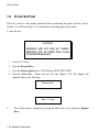
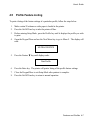
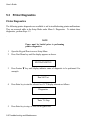
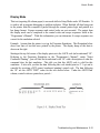
4.6
Changing Features in a Profile
Feature settings in a profile may be changed through the keypad by following the steps
below:
1.
Press the On/Off Line key to take the printer off line.
2.
Press Park key to park paper.
3.
Press the Profile key to select profile being changed.
4.
Open the Keypad Door.
5.
Press the Next Menu key, as necessary, to scroll through the feature menus until you
reach the menu containing the feature you wish to change.
6.
Press the Feature ▲ or the Feature ▼ key to scroll the display up or down until you
reach the feature to be changed.
7.
Press the Value ▲ key or the Value ▼ key to scroll the display backward or forward
until you reach the value you wish to set.
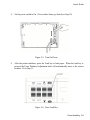
Figure 4-2: Changing Features in a Profile
8.
Press the Enter key to record the new value.
4-8 Features and Profiles
User’s Guide
9.
Repeat Steps 5 through 8 as necessary until all features are correctly set for your
application.
10. Close the Keypad Door to exit Setup Mode. The alternating display will read:
Press ‘Profile’
To Save Settings
To answer “Yes”, press the Profile key. This will permanently record the change in
non-volatile memory for that profile.
To answer “No”, press any other key. This will make the change temporary, thus not
changing the original profile setting. These settings will be valid until profiles are
changed again or the printer is powered off.
11. Press Load key to load paper (resets top-of-form).
12.
Press the On/Off Line key to return to operation.
NOTE
To maintain correct top-of-form alignment
when a profile change is made, the paper
should be parked (if not already parked) and
reloaded so that the printer can reset the topof-form for the new profile.
Features and Profiles 4-9
User’s Guide
As an example, assume the profile you are presently using defines the lines per inch as 6. To
permanently change the lines per inch to 8, proceed as follows:
1.
Press the On/Off Line key to take the printer off line.
2.
Press Park key to park paper.
3.
Open the Keypad Door to enter Setup Mode.
4.
Press the Feature ▲ key to select Lines/Inch.
5.
Press the Value ▼ key to change the Lines/Inch to 8 lines.
6.
Press the Enter key to save the new Lines/Inch value.
7.
Close the Keypad Door to exit Setup Mode. The LCD will read:
Press ‘Profile’
To Save Settings
Press Profile key to save entry.
8.
Press the Load key to load paper (resets top-of-form).
9.
Press the On/Off Line key to place the printer back on line.
After pressing the On/Off Line key, the printer will operate with the vertical motion defined
as 8 lines per inch. The next time this profile is selected, or if the printer power is switched
off and back on, the lines per inch margin will remain at 8 lines per inch.
4-10 Features and Profiles
User’s Guide
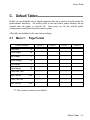
4.7
User Programmable Features
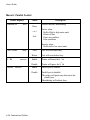
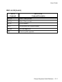
Menu 1: Page Format
Printer Displays
Lines/Inch
###
Form Length
Top Margin
Bottom Margin
Left Margin
Right Margin
###
###
###
###
###
Values
1
2
3
4
6
8
12
1
.
.
200
1
.
.
.
200
1
.
.
.
200
1
.
.
MLL
LM
.
.
MLL
Description
Vertical pitch for printing text in lines per inch.
Lines per page resets top and bottom margins.
Value cannot exceed bottom margin.
Number of lines from the top-of-form and the
first print line.
Value cannot exceed form length.
Bottom margin
The last print line allowed on the form
Value cannot exceed form length.
The left margin can be set from 1 to the right
margin.
Maximum Line Length (See Appendix A)
Clear Horizontal Tabs
Pressing the Enter key will clear all horizontal
tabs.
Maximum Line Length (See Appendix A)
Features and Profiles 4-11
User’s Guide
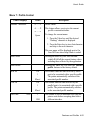
Menu 1: Page Format (Cont’d)
Printer Displays
Values
Description
Clear Horz Tabs
Clear Horizontal Tabs
Horz Tab
Pressing the Enter key will clear all horizontal
tabs.
Horizontal Tabs
### xxx
Set/Clr
Pressing the Value key selects the column (#)
where a horizontal tab may be set or
cleared.
Pressing the Enter key will Set or Clr (clear) a
tab in that column
Clear Vert Tabs
Clear Vertical Tabs
Pressing the Enter key will clear all horizontal
tabs.
Vert Tab
### xxx
Set/Clr
Vertical Tabs
Pressing the Value key selects the line (##)
where a vertical tab may be set or cleared.
Pressing the Enter key will Set or Clr (clear) a
tab in that line.
4-12 Features and Profiles
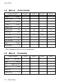
User’s Guide
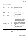
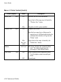
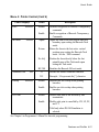
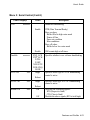
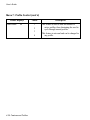
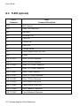
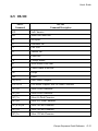
Menu 2: Forms Control
Printer Displays
Load ###/144”
Load Crg Mov
Values
Description
0 0/144
.
.
.
.
.
Current
Form
Length
In Inches
This feature is used to align the first printline
of a form and the printhead. This feature is
normally set using the Adjust Form key.
This feature is active only during paper
loading.
###
Increments are in inches or 1/144th of an inch.
This feature determines if the print head moves
during a Load function. This feature is only
used during paper loading.
On
The print head will move while the paper is
being loaded. This normally will prevent
fanning of a multi-part form.
Off
The print head will stay to the far right of the
carriage. No motion will occur until the
printer seeks the thickness of the form.
Horz Adj xxx/144”
0/144
.
.
.
144/144
This feature allows the user to logically offset
the form horizontally to the left, up to 1
inch. This feature is active immediately
when set.
Tear x xxx/144”
0 0/144
.
.
.
11 0/144
This feature determines the distance the paper
is moved when the Tear Off key is pressed.
Features and Profiles 4-13
User’s Guide
Menu 2: Forms Control (Cont’d)
Printer Displays
Manual Tear
xxx
Manual Time ###s
Auto Tear
Values
FF
4-14 Features and Profiles
The printer will perform a form feed before
moving to the tear position after pressing
the Tear Off key.
TOF
The printer will move to the tear position after
printing crosses the next forms boundary
after pressing the Tear Off key.
No FF
This value will move the paper the tear
distance only. No form feeds are
performed.
The Tear Off key must be pressed to return the
forms to the print position.
OFF
xxx
Description
1
.
.
The time in seconds that the form will be in the
tear position before automatically returning
to the print position.
30
This feature works only with the Manual Tear
key.
OFF
Values set for “Off”, the printer will not move
the form into the tear position if the form is
at top and no data is being transmitted.
IDLE
Value set for “Idle”, the printer will move the
form into the tear position if the form is at
top and no data is being transmitted.
PAGE
Moves the form to the tear bar position on
every page break while on line. The form
will retract after the time specified by the
“Auto Time X” feature has expired.
User’s Guide
Menu 2: Forms Control (Cont’d)
Printer Displays
Auto Time
###s
HF: Pos crg
x.x”
Values
Description
1
.
.
.
.
.
.
30
0.0”
0.1”
0.2”
.
.
.
9.8”
The time in seconds that the form will be in the
tear position after more data is sent to the
printer.
HF: xxxxxxxxxxxx
This feature works only when the Auto Tear
feature is ON.
Specifies the position of the carriage, when the
Heavy Forms feature is enabled. The
maximum value is dependent on the current
value of the Horz Adj xxx/144” feature.
Specifies when the Heavy Forms sequence is
initiated.
On Feed
> x.x”
0.0”
0.1”
0.2”
.
5.0”
On a paper feed greater than x.x inches the
carriage is positioned to the location
specified by the HF:Pos crg x.x” feature.
The default = .5” which is 3 lines @6 LPI.
On page
break
On a form feed (FF) or paper move that
crosses a forms boundary or bottom margin
(page break), the carriage will be positioned
to the location specified by the HF: Pos crg
x.x” feature.
Disabled
Heavy forms sequence is disabled.
Features and Profiles 4-15
User’s Guide
Menu 2: Forms Control (Cont’d)
Printer Displays
Path xxxxx
Paper Speed
###
4-16 Features and Profiles
Values
Either
Main
Alt.
3
.
.
.
.
15
Description
Allows the current profile to be paper path
specific.
This feature controls the paper feed speed in
inches per second.
Slower speeds may improve paper handling of
certain forms.
User’s Guide
Menu 3: Personality
Printer Displays
Emulate xxxxxxxx
Values
IBM Pro
IBM Grph.
LA 120
Epson FX
DS-180
Display
Font xxxxxxxxxx
DP 10
DP 12
DP 13.2
DP 15
DP 16
DP 16.5
DP 17.16
DP 18
DP 20
Description
This feature selects the desired emulation.
Escape sequences for each emulation are listed
in the “Programmer’s Manual.”
Hex display feature, see “Troubleshooting and
Maintenance” for further information.
Data processing fonts.
Italic print quality will vary when using DP
fonts.
Draft 10
Draft 12
Draft 13.2
Draft 15
Draft 16
Draft 16.5
Draft 17.16
Draft 18
Draft 20
Draft fonts (9 x 12 matrix)
Courier 10
Prestige 12
OCR_A 10
OCR_B 10
NLQ font (18 x 24
NLQ font (18 x 20
NLQ font (18 x 36
NLQ font (18 x 36
10 cpi)
12 cpi)
10 cpi)
10 cpi)
Features and Profiles 4-17
User’s Guide
Menu 3: Personality (Cont’d)
Printer Displays
Set xxxxxxxxx
7 Bit ASCII
DEC Supplmt1
IBM Code 437
IBM Code 850
Epson Italic
Epson Graph
Epson Ital/Gr
USA
UK
France
Germany
Italy
Switzerland
Canadian Fr
Japan
Latin Am
Spain
Denmark
Norway
Finland
Sweden
Spain II
Denmark II
Sp/Lat Am
Nor/Den
Swed/Fin
1 or 2
Nat. xxxxxxxx
IBM CHAR Set
Print Zero as
Values
#
4-18 Features and Profiles
Description
Refer to “Programmer’s Manual” for
character tables.
All nationalities are available in all symbol
sets, fonts, and emulations (except OCR A
and B) using Setup Mode. The actual
nationality selected using emulation escape
sequences vary depending on emulation.
Refer to the Programmer’s Manual for
each emulation.
0
Prints Zero without a slash
Ø
Prints Zero with a slash
User’s Guide
Menu 4: Printer Control
Printer Displays
Auto LF
xxx
Auto CR
xxx
Wrap
Print
xxx
xxxxxxxx
Auto Path SW
Vert Graphic
Horz Graphic
Values
xx
xxx
xxx
Description
Disable
No line feed with carriage return.
Enable
Performs a line feed with carriage return.
Disable
No carriage return with line feed.
Enable
Performs a carriage return with line feed.
Disable
Printable data past the right margin is ignored.
Enable
Performs a carriage return line feed if data
exceeds the right margin.
Bidirect
Bi-Directional printing
Unidirect
Unidirectional printing prints left-to-right only.
ON
When this feature is set to ‘ON’ and a paper
out occurs while printing, the printer will
automatically change to the other paper
path and continue printing if the forms are
loaded successfully.
OFF
This feature is valid only on dual tractor units.
ON
Specifies status of the TI-885 raster graphics
mode
OFF
When ON Anadex graphics is enabled when
DS-180 Emulation is selected.
Specifies status of the TI-885 horizontal
graphic mode
ON
OFF
Power Up
xxxxxxxx
On Line
Specifies whether printer powers up into on
line or off line status
Off Line
Features and Profiles 4-19
User’s Guide
Menu 4: Printer Control (Cont’d)
Printer Displays
Buffer Size
Window Size
xxxx
xxxx
Ribbon
Dble Strike
xxx
4-20 Features and Profiles
Values
512
.
.
.
.
.
Max
256
.
.
.
.
.
.
Max
Size Less
1024
##% Used
Description
Specifies the size of the data buffer.
Lower limit of this range may be limited by
“Window Size” feature.
Depends on buffer option installed
Window (FIFO size)
Specifies how many bytes of data must be
emptied out of a full data buffer before the
communication interface will go into the
“Ready” mode
Upper limit of this range is limited by the
“Buffer Size” feature.
This feature displays the estimated ribbon
used. The value is based upon the
percentage of Max Ribbon feature.
ON
Prints in unidirectional emphasized mode.
Used for higher contrast on multi-part
forms
OFF
Normal print.
User’s Guide
Menu 4: Printer Control (Cont’d)
Printer Displays
DGCL
xxxxxxx
Exit Mode
xxxxxx
Command Char
xxx
Values
Description
Disable
Disables recognition of Barcode Transparency
commands
Enable
Enable recognition of Barcode Transparency
Commands
Adjust the form to the next logical line feed
boundary upon exiting the Barcode Task
mode.
Adjust
Return
Return the form to the last active vertical
position upon exiting the Barcode Task
mode. See the ^J000 command
No Adj
Position the form directly below the last
printable pass of the Task mode upon
exiting the Task mode
BC-300
33
Emulates the Barcode 300 exit mode.
Defines the default command character
255
Overlap
DW Term
xxxxxxx
Example: 94 represents the [^] character
Disable
Disables one dot overlap when printing
barcodes
Enable
Enables one dot overlap when printing
barcodes
Disable
Double wide print is not affected by line
terminations
Enable
Double wide print is cancelled by CR, LF, FF,
and VT
Valid only when DS-180 Emulation is
selected.
See Chapter 6 in Programmer’s Manual for barcode programming.
Features and Profiles 4-21
User’s Guide
Menu 5: Serial Control
Printer Displays
Baud Rate
Serial
Parity
Data Bits
xxxx
xxxxx
xxxxx
xxxxxxx
4-22 Features and Profiles
Values
Description
110
300
600
1200
1800
2400
4800
9600
19.2k
RS-232
Refer to the documentation of your host
computer to determine the baud rate.
RS-422
Cable must be configured to match. See
Appendix B
Selects serial configuration
OFF
Selecting OFF disables both serial
configurations.
None
Even
Odd
Space
Mark
Refer to the documentation for your host
computer to determine parity.
7
8
Refer to the documentation for your host
computer to determine data bits.
Space 8th Bit only
Mark 8th Bit only
User’s Guide
Menu 5: Serial Control (Cont’d)
Printer Displays
DTR
Handshk
X-ON Ctrl
X-OFF Ctrl
Modem Ctrl
Values
xxxxxxx
xxxxxxx
Description
Hardware Handshaking
Enable
DTR (Data Terminal Ready)
Busy on when:
Buffer filled to high water mark
Printer off line
Paper out condition
Error conditions
Busy off when:
Buffer below low water mark
Disable
Will remain high at all times.
Specifies whether to use software handshaking
xxx
ENQ_ACK
EXT_ACK
X-ON/
X-OFF
XON+ETX
XON+ENQ
NONE
Single
xxx
Robust
Single
xxx
Robust
On
Off
Specifies which type of X-ON Handshaking
control is active
Specifies which type of X-OFF handshaking
control is active
Activates the following signals:
RTS (Request to Send)
CTS (Clear to Send)
Disables the above signals (RTS is held high)
Features and Profiles 4-23
User’s Guide
Menu 6: Parallel Control
Printer Displays
Handshk on
xxxx
Values
Busy
< or >
Ack
Ack xxxxxx
8th Bit
Busy
xxxxxxx
Parallel xxxxxxx
4-24 Features and Profiles
After
Description
Parallel interface handshaking
Active when:
Buffer filled to high water mark
Printer off line
Paper out condition
Error conditions
Inactive when:
Buffer below low water mark
Ack will occur after busy.
Before
Ack will occur before busy.
Enable
Printer will honor the 8th bit.
Disable
Printer will ignore the 8th bit
Enable
Parallel port is enabled.
Disable
Parallel port is disabled.
The printer will ignore any data sent to the
parallel port.
Handshaking will indicate busy.
User’s Guide
Menu 7: Profile Control
Printer Displays
Rename: xxxxxxxx
Values
Description
0 ….. 9
Profile Name
A ….. Z
This feature allows you to give the current
profile a customized name.
a ….. z
Space
To change the current name:
1. Press the Value key until the desired
“flashing” character is displayed.
2. Press the Enter key to store that character
and skip to the next character.
This new name will be displayed next to On
Line/Off Line when Setup Mode is exited.
Save Profile
Pressing the Enter key will save into nonvolatile RAM all the current feature values
including those affected by the application.
Reset Profile
Pressing the Enter key will reset the current
profile features to the factory default.
SER Prt
Off
1
.
Max #
This feature links the data received by serial
port to be associated with a specific profile.
The printer automatically switches to the
associated profile number.
PAR Prt
Off
1
.
Max #
This feature links the data received by the
parallel port to be associated with a specific
profile. The printer automatically switches
to the associated profile number.
1
.
1200
This feature is used to determine how long the
printer waits before accepting data from a
different interface.
Port Time
###s
Features and Profiles 4-25
User’s Guide
Menu 7: Profile Control (cont’d)
Printer Displays
Max Profile
xx
Values
Description
1
This feature is used to limit the number of
active profiles, thus eliminating the need to
cycle through unused profiles.
2
3
4
4-26 Features and Profiles
This feature is universal and can be changed in
any profile.
User’s Guide
Menu 8: Form Thickness Control
Printer Displays
Values
Auto Form Gap
Description
Allows the user to perform an immediate
automatic form thickness adjustment.
Thickest part of form should be used when
making this adjustment.
Quiet or Whisper
Adj. Form Gap
High
Medium
Low
xxx
0-198
Units
This feature determines method and impact of
a print line.
Quiet – the printer prints at full character per
second values.
Whisper – the printer prints half of the
character in the first pass and the other half
in the second pass.
The high, medium and low values are available
in specific optional configurations.
Allows the user to specify/change the form
thickness distance.
Pressing Value ▲ key causes form thickness
gap to decrease by 1 unit.
Pressing Value ▼ key causes form thickness
gap to increase by 1 unit.
Hor Gap Pos
xx.x
VR Gap Pos xx.x
0.0”
.
.
8.8”
0.0”
.
.
Form
Length in
inches
Allows the user to have the printer perform
auto form gapping at any horizontal
position on the print line in tenths of an
inch.
Allows the user to have the printer perform
auto form gapping at any vertical position
on the paper.
This is in tenths of an inch and is limited by
the current form length.
Features and Profiles 4-27
User’s Guide
Menu 9: Diagnostics
Printer Displays
Values
Print Profile
Description
Pressing the Enter key will print the current
profile features.
Paper must be loaded in the printer before
pressing the Enter key. to stop test, close
the Keypad Door or press the Enter key.
P/N: ######
xx
Test Printhead
Firmware revision number
Pressing the Enter key will result in testing
each printwire in the printhead.
Paper must be loaded in the printer before
pressing the Enter key. To stop test, close
the Keypad Door or press the Enter key.
Run Mode test
Pressing the Enter key will result in printing
font renditions (Double-high, Emphasize,
etc.) in the current symbol set.
Paper must be loaded in the printer before
pressing the Enter key.
To stop the test, close the Keypad Door or
press the Enter key.
Run Self Test
Pressing the Enter key will result in printing an
ASCII ripple pattern.
Paper must be loaded in the printer before
pressing the Enter key.
To stop the test, close the Keypad Door or
press the Enter key.
4-28 Features and Profiles
User’s Guide
Menu 10: System Control
NOTE
Refer to Appendix D for instructions on
accessing Menu 10.
Features and Profiles 4-29
User’s Guide
4-30 Features and Profiles
User’s Guide
5.
Troubleshooting and Maintenance
5.1
Scheduled Maintenance
This chapter provides scheduled maintenance and troubleshooting procedures that can be
performed by the operator. A qualified technician should perform any troubleshooting or
maintenance beyond the level presented in this chapter.
WARNING
MAKE CERTAIN THE PRINTER IS
DISCONNECTED FROM THE AC POWER
SUPPLY BEFORE REACHING INTO THE
UNIT TO PERFORM ANY CLEANING OR
MAINTENANCE TASK.
CAUTION
DO NOT USE CLEANERS, SOLVENTS OR
LUBRICANTS ON ANY OF THE
WORKING PARTS OF THE PRINTER.
The scheduled maintenance that should be performed is periodic cleaning (approximately
every 3 months). Clean the cover with a soft, non-abrasive cloth.
Troubleshooting and Maintenance 5-1
User’s Guide
Use a small vacuum cleaner to remove dust from the carriage, platen, paper tractors, paper
out sensors, and printer throat. A dry, lint-free cloth may be used to clean accumulated dirt
from the carriage shafts and the platen.
Figure 5-1: Cleaning the Printer
5-2 Troubleshooting and Maintenance
User’s Guide
5.2
Error Message
Paper Out Condition (Main Tractors)
When the printer runs out of paper, the following message will appear in the display:
< Paper Out: Main>
The printer will automatically go off line when the paper supply is depleted. To recover from
a paper out condition:
1.
Load paper into the main tractors.
2.
Press the Load key to load forms.
3.
Press the On/Off Line key to go back on line.
The error message will be cleared from the display after paper is loaded.
Figure 5-2: Main Tractor Path
Troubleshooting and Maintenance 5-3
User’s Guide
Paper Out Conditions (Alternate Tractors)
< Paper Out: ALT >
When the alternate tractors run out of paper, the following message will appear in the display:
1.
Load paper into Alternate tractors.
2.
Press Load key to load forms.
3.
Press On/Off Line key to continue.
The error message will be cleared from the display after paper is loaded.
Figure 5-3: Alternate Tractor Path
5-4 Troubleshooting and Maintenance
User’s Guide
Paper Jam
Paper jams may occur for several different reasons including: incorrect forms loading, form
thickness adjustment set too close, or form out of specification. Check the value of the
features that may affect form thickness adjustment: horizontal gap, vertical gap, heavy forms,
and adjust form gap.
To clear a paper jam:
1.
Turn the printer off.
2.
Manually rotate the Form Thickness Adjustment Knob counterclockwise so that the
printhead is the maximum distance away from the platen.
3.
Open the Access Cover.
4.
For tractors: Paper that has not reach the platen may be removed by opening the
tractors and pulling the paper straight down.
5.
For cut sheet: Paper that has not reached the platen can be dislodged by pressing Park
and/or Line Feed and by the paper straight out.
6.
Carefully, remove all paper fragments. Make certain no paper fragments are left on the
platen, ribbon guide, or paper sensor. Make certain ribbon and guide are factory
approved and are in the correct position and not twisted.
7.
Close the Access Cover.
8.
Turn the printer power on. When the power is switched on, the printer resets the
carriage and checks the paper path. The printer will indicate a paper out condition if
paper needs to be reloaded.
9.
Reload paper as necessary.
10. The form thickness adjustment will automatically reposition for normal operation.
Troubleshooting and Maintenance 5-5
User’s Guide
Carriage Jam
If the carriage is unable to move because of foreign objects in the printer or because of
mechanical failure, the following messages will alternate in the display:
< Carriage Jam >
Press On/Off Line Key
To recover from this error condition:
1.
Press the On/Off Line key to take the printer off line.
2.
Open the Access Cover.
3.
Clear the obstruction and make certain the carriage can move freely.
WARNING
PRINTHEAD MAY BE HOT.
4.
Close the access cover.
5.
Press the On/Off Line key to place the printer on line. When the printer goes on line,
the printer will reset the carriage, check the paper path, and clear the error message
from the display. The printer will indicate a paper out condition if the paper needs to
be reloaded.
6.
The form thickness adjustment will automatically reposition for normal operation.
5-6 Troubleshooting and Maintenance
User’s Guide
Keypad Lockout
The following message is displayed momentarily after pressing a key which has been locked
out or delayed:
>> Key Locked <<
This feature can be changed by using the instructions located in Appendix D.
Troubleshooting and Maintenance 5-7
User’s Guide
5.3
Printer Diagnostics
Printer Diagnostics
The following printer diagnostics are available to aid in troubleshooting printer malfunctions.
They are accessed while in the Setup Mode under Menu 9: Diagnostics. To initiate these
diagnostics, perform Steps 1-5
.
NOTE
Paper must be loaded prior to performing
printer diagnostics.
1.
Open the Keypad Door to access Setup Menu.
2.
Press Next Menu key until the display appears as shown.
M9 DIAGNOSTICS
3.
Press Feature ▼ key until display indicates name of diagnostic to be performed. For
example:
Run Self Test
4.
Press Enter key to start the selected test. LCD display alternate as follows:
Diagnostics
‘Enter’ To Stop
5.
Press Enter key to stop, or close the Keypad Door.
5-8 Troubleshooting and Maintenance
User’s Guide
Print Profile
This test will print a complete listing of feature settings for the current profile. This is
normally used to obtain a quick list of the printer feature settings that can be compared with
the computer system.
Figure 5-4: Print Profile
5-7
Troubleshooting and Maintenance 5-9
User’s Guide
Figure 5-4 (cont’d): Print Profile
5-10 Troubleshooting and Maintenance
User’s Guide
P/N: 104217 – xx (Firmware Part Number)
This test is normally used by service personnel to determine what level and type of firmware
is installed in the printer. The test is included in the “Print Profile ” feature, Figure 5-4, M9
Diagnostics.
Troubleshooting and Maintenance 5-11
User’s Guide
Test Printhead
This test verifies that the individual printhead impact wires and the controlling electronics are
operating properly. It may be used to identify the cause if dots are missing on the print out.
In this test, one complete line is printed using each wire in the printhead. The wire is noted in
the test print out.
NOTE
To prevent print off the page, 80 column
paper should be used for this test.
Figure 5-5: Printhead Test
5-12 Troubleshooting and Maintenance
User’s Guide
Run Mode Test
This test (requiring 80 column paper) will print the current Symbol set in all fonts available in
the printer.
Troubleshooting and Maintenance 5-13
User’s Guide
Run Self Test
This test (requiring 80 column paper) will print an ASCII ripple pattern and will test the
internal logic of the printer. If this test runs, the printer has passed all internal diagnostics.
5-14 Troubleshooting and Maintenance
User’s Guide
Display Mode
This test (requiring 80 column paper) is accessed while in Setup Mode under M3 Emulate. It
is used to aid in program debugging or problem isolation. When Enabled, all data being sent
to the printer from the computer is passed through the normal printer logic and printed in a
hex dump format. Escape sequences and control codes are not executed. The output from
the display mode can be compared to the control codes and escape sequences listed in the
“Programmer’s Manual”. With this information you can determine if escape sequences are
correct for the emulation selected.
Example: Assume that the printer is set up for Proprinter Emulation. The illustration below
shows two lines of text that were printed by the printer. The display dump of this data is
shown on the right.
Starting at the top left corner of the display print out is the ASCII code (in hexadecimal) ‘0F’.
Referring to the Proprinter Emulation in the “Programmer’s Manual”, under “Select
Condensed Printing”, you will find the hexadecimal code ‘0F’ with a description of what the
command does for that emulation. This tells you that this ASCII code is valid for this
emulation. It also tells you that the data following this code should print in 17.1 cpi and is
canceled by receiving a DC2 (cancel condensed printing) control code. The data following
the ‘0F’ are the ASCII “HEX” codes for the text shown below. Under the ASCII Data
column, control codes are printed as a period <.
Troubleshooting and Maintenance 5-15
User’s Guide
5.4
Troubleshooting
NOTE
Please read this section before continuing to
symptom analysis.
The following diagnostic tests are used to aid in isolating possible printer malfunctions.
These tests will assist the operator in determining printer/host problems. Additional
information for printer error recovery is described under Error Messages. For host to printer
communication problems, it is suggested that the operator read the Interface Functional
Description of this manual prior to symptom analysis. The operator should also be familiar
with displaying and setting of printer features. Refer to the chapters on “Features” for this
information.
The following section lists symptoms and corrective actions to be performed for each
symptom. Prior to starting the symptom analysis, it is suggested that the printer be powered
off for approximately 30 seconds and then powered back on. This will clear any possible bad
data in memory and reload Profile settings. Verify settings by running the Print Profile
diagnostic as described on Pages 5-9, and compare the output to your desired configuration.
If no changes are needed, rerun the print job. If the problem persists, go to the
Troubleshooting Table and locate the symptom that best describes the problem you are
experiencing. Perform the corrective actions listed for the symptom. If the problem still
exists after performing the corrective actions, or if there is not a symptom that corresponds to
the problem you are experiencing, call a qualified technician for further assistance.
In the table, some corrective actions indicate to the operator to check a ‘Feature Value’ to
make sure it is set correctly. An incorrect feature value can vary between host systems,
applications, configurations, etc., and may cause the particular symptom. For example:
The operator may need to check the setting of the Parallel Enable/Disable feature found under
Menu 6 (Parallel Control) and verify that the Parallel port is Enabled.
5-16 Troubleshooting and Maintenance
User’s Guide
5.5
Troubleshooting Table
Symptom
No Host Communication
Serial
Corrective Action
Verify properly selected profile.
Check interface cable (pin outs), cable connections, or try
a new cable.
Verify emulation selected.
Verify baud rate, serial type (RS-232, RS-422), parity,
data bits, DTR, handshaking
Is serial port disabled?
Reset profile and re-setup the printer.
No Host Communication
Parallel
Verify properly selected profile.
Check interface cable (pin outs), cable connections, or try
a new cable.
Verify emulation selected.
Handshaking (Ack and/or Busy), 8th bit control
Is parallel port disabled?
Reset profile and re-setup the printer.
No Power/Blank Display
Verify power plug connection to the printer.
Verify power plug connection to power outlet.
Try another power outlet.
Check main fuse located on the rear of the printer. Ensure
that voltage switch is set properly.
Troubleshooting and Maintenance 5-17
User’s Guide
Symptom
Paper Feeding Problems
Tractors
Corrective Action
Verify power plug connection to the printer.
Verify paper tension. Adjust tractors if paper is too tight
or too loose causing buckling (See Section 3.3)
Make sure the paper holes are aligned properly in tractors.
Equally space rear paper supports and front paper guides
between tractors.
Verify forms are hanging straight down from the tractors
and the front of the printer is aligned with the edge of
the table top or stand.
Verify that the ribbon guide is fully seated on the
printhead.
Verify that there are no twists in the ribbon.
Do not print off the edge of the form or on the paper
staples. Verify that the left tractor is positioned to the
alignment mark and that the left and right margins are
set properly.
Verify form thickness is within the specification.
Verify Heavy Forms feature setting is on (See Sections 3.6
– 3.7).
Reduce print speed (under M2 Forms Control in Setup
Mode) and/or move paper to Main paper path on dual
path units only.
5-18 Troubleshooting and Maintenance
User’s Guide
Symptom
Paper Feeding Problems
Cut Sheet *
Corrective Action
Remove any paper jams by pressing Line Feed and
Adjust ▲ or ▼.
Turn power off, open Access Cover and remove any
foreign objects. Adjust the right edge guide to the
correct width and reload paper. (See Section 3.3)
If form is 4.5 inches to 6.0 inches long, verify that the
Vertical Gap position is set to 0.0 inches (located under
M8: Form Thickness. See Sections 4.6 – 4.7)
Reduce Paper Speed (located under M2: Forms Control.
See Sections 4.6 – 4.7)
If vertical spacing is not exactly 6 or 8 lines/inch
(exceptionally thick, stiff, and long forms), adjust Cut
Sheet Comp. feature value.
Skewed Print On Cut Sheet
Forms
Make sure to grab the form in the center and align left
edge of the form against the left edge guide.
Verify the right edge guide is positioned properly against
the form.
Reduce the Paper Speed (located under M2: Forms
Control. See Sections 4.6 – 4.7)
Improper Print Alignment
between first and last
sheet of form
(Delamination)
Keep Top Exit Cover closed while printing. Do not allow
form to spill over front of printer. Do not touch the
form as it is printing.
Reduce Paper Speed (located under M2: Forms Control
See Sections 4.6 – 4.7)
Verify that the form thickness setting is correct for the
application and increase forms thickness setting, if
necessary.
* To avoid vertical inaccuracy, do not print using Double High, Double Strike, Superscript, or Twelve
dot high characters over the last 2 inches of a cut sheet form.
Troubleshooting and Maintenance 5-19
User’s Guide
Symptom
Carriage Jam
Corrective Action
Turn off power, open front Access Cover, and check for
foreign objects.
Verify label is not stuck to the ribbon guide.
Verify form thickness setting.
No Print
Verify installation of ribbon and ribbon guide.
Run a self-test. See “Diagnostic Tests”
Verify form thickness setting as described under the
“Form Thickness Adjustment” of this manual.
Short Ribbon Life
Inspect failed ribbon. Ribbon should have two distinct
wear bands. If only one band is visible, ribbon is
defective.
If ribbon fabric shows vertical runs, printhead gap is too
small or printhead is damaged. Check print gap and
printhead.
Ribbon life can be affected by application. Heavy
graphics, barcode and NLQ printing can shorten ribbon
life.
Prints Garbage
Parallel
Verify properly selected profile.
Check interface cable (pin outs), cable connections, or try
a new cable.
Verify emulation selected.
Handshaking (Ack and/or Busy), 8th bit control
Reset profile and re-setup the printer.
5-20 Troubleshooting and Maintenance
User’s Guide
Symptom
Prints Garbage
Serial
Corrective Action
Verify properly selected profile.
Check interface cable (pin outs), cable connections, or try
a new cable.
Verify emulation selected.
Verify baud rate, serial type (RS-232, RS-422), parity,
data bits, DTR, handshaking.
Reset profile and re-setup the printer.
Loss of Data
Buffer Overflow
Parallel
Check interface cable (pin outs), cable connections, or try
a new cable
Verify emulation selected.
Handshaking (Ack and/or Busy), 8th bit control
Reset profile and re-setup the printer.
Loss of Data
Buffer Overflow
Serial
Check interface cable (pin outs), cable connections, or try
a new cable
Verify emulation selected.
Verify baud rate, serial type (RS-232, RS-422), parity,
data bits, DTR, handshaking.
Reset profile and re-setup the printer.
Printhead Moves but No
Printing Occurs
Check Form Length feature. Form length must be equal
to the length of the form being used.
Printhead Pauses at End of
Print Lines
Printhead thermal protection is activated. Make sure
printer has proper air flow and is not located in an
excessively hot area. Printer will exit this mode
automatically after cooling.
Troubleshooting and Maintenance 5-21
User’s Guide
Symptom
Printer Will Not Switch Paths
Corrective Action
Change the Path Value to “Either” under M2: Forms
Control. (See Section 3.8 – 3.13).
Verify the Config feature in M10 matches the
configuration of the printer.
First Print Line Location is
Wrong
Readjust the first print line using the instructions in
Section 3.4.
Print Contrast on Last Sheet
is Too Light
Verify the forms thickness setting is correct for the form
being used.
Enable the High Impact feature under M4: Printer Control
(See Section 4.6 – 4.7)
Select an NLQ font listed in Section 3.4.
Printer is Too Noisy
Enable Quiet Mode feature under the M8: Form
Thickness Control. (See Section 4.6 – 4.7).
5-22 Troubleshooting and Maintenance
User’s Guide
A.
Printer Specifications
A.1
Printer Characteristics
•
Printhead:
9 wire with a rated life of 200,000,000 draft characters.
•
Maximum Line Length:
Main Tractor Path 8.8 inches (223mm)
(88 columns @ 10 cpi)
Alternate Tractor Path 8.8 inches (223mm)
(88 columns @ 10 cpi)
•
Vertical Pitch:
1, 2, 3, 4, 6, 8 and 12 lines per inch and variable spacing, depending on the emulation.
A.2
Emulations
•
Epson FX-80
•
DEC LA-120
•
IBM Graphic Printer
•
IBM Proprinter XL
•
DS-180
Printer Specification A-1
User’s Guide
A.3
•
Font Specifications
Available Fonts/Typefaces:
Pitches
Matrix (H x W)
Print Speed
(CPS)
10, 12*, 13.2, 15, 16.5,
17.16, 18, 20
9 x 10
300
10, 12, 13.2, 15, 16, 16.5,
17.16, 18, 20
9 x 12
250
Courier
10
18 x 24
62
Prestige
12
18 x 20
75
Helvetica
12
18 x 24
75
OCR A
10
18 x 36
42
OCR B
10
18 x 36
42
DP
Draft
* 9 x 9 at 333 cps
•
Graphic Densities:
Horizontal
Dots/Inch
60
72
80
90
120
240
A-2 Printer Specifications
Vertical
Dots/Inch
72 dots/inch and variable spacing,
depending on emulation
User’s Guide
•
International Character Sets :
Epson Nationalities
DEC Nationalities
USA
USA
France
U. K.
Germany
Finland
U. K.
Sweden
Denmark I
Norway/Denmark
Sweden
Germany
Italy
France
Spain I
Japan
Norway
Denmark II
Spain II
Latin America
Printer Specification A-3
User’s Guide
A.4
•
Paper Feed Specifications
Paper Types:
Main Tractor: 3 ½ inches to 10 5/8 inches (88.9 mm to 269.8 mm), 1 to 9 part, .028
inches (.127 mm) max. thickness. Individual parts not to exceed .005 inches (.711 mm)
thickness without factory approval.
Alternate Tractor: 3 inches to 10 ½ inches (76.2 mm to 266 mm), 1 to 9 part, .28 inches
(.127 mm) max. thickness. Individual parts not to exceed .005 inches thickness (.711
mm) without factory approval.
Cut Sheet: 2 ¾ inches to 10 5/8 inches (69.8 mm to 269.8 mm), 1 to 9 part, .028 inches
(.127 mm) max. thickness. Individual parts not to exceed .005 inches thickness (.711
mm) without factory approval.
•
Paper Access:
Bottom – Main Tractor Path
Front – Alternate Tractor Path or Cut Sheet Path
•
Feed Direction:
Forward – Continuous
Reverse – Continuous
•
Forms Tear/Off:
Zero forms tear off
•
Paper Slew (Paper Advance):
Slew speed is 15 IPS (inches per second) and is programmable. Cut sheet slew is 10 IPS
maximum.
A-4 Printer Specifications
User’s Guide
A.5
•
Forms Mode Change
Parking Forms :
The forms are reverse fed into the tractors, so that the alternate paper path may be
selected. The new forms are then reloaded to the previously set top-of-form and top
margin.
•
Tear Off:
A key may be used to advance the forms a predefined distance, so the last printed form
can be removed without wasting the next form. The distance advanced is programmable
by the user. The forms are returned to print position when the key is pressed again, or
after a user specified timeout period.
A.6
•
Communications Interface
Communications Buffer Size :
3K to 128K depending on RAM option installed.
programmable.
•
Size and handshaking limits are
RS-232/RS-422 Serial Interface Characteristics:
Baud Rates: 110, 300, 600, 1200, 1800, 24,00, 4800, 9600, 19.2Kb
Protocol Types: X-ON/X-OFF, ETX/ACK, ENQ/ACK, DTR
•
Centronics – Compatible Parallel Interface Characteristics :
36 pin Amphenol Configuration
Protocol Types: BUSY, ACK
Printer Specification A-5
User’s Guide
A.7
•
Operator Panel Functional Description
Display Description:
1 line by 16 character LCD. In addition, an LED is used to indicate READY (On Line)
status.
•
Keyswitch Layout:
8 keys
A.8
Ribbon Cartridge/Drive
Stationary cartridge with an average life of 7-10 million characters (depending upon printing
application).
A.9
Physical
17.0 inches (431mm) wide x 15.7 inches (398mm) deep x 12.3 inches (312mm) high (Dual
Tractor Top Roller version)
17.0 inches (431mm) wide x 15.7 inches (398mm) deep x 11.3 inches (287mm) high
(Standard Model)
17.0 inches (431mm) wide x 16.7 (424mm) inches deep x 12.3 inches (312mm) high (Cut
Sheet Model)
Weight: 45 lbs (20.4 Kg) (Standard and Dual Tractor Model); 46 lbs (20.9 Kg) (Cut Sheet
Model)
A-6 Printer Specifications
User’s Guide
A.10 Electrical
•
Power Requirements:
97 V to 132 V, 57 to 63 Hz
195 V to 264 V, 47 to 53 Hz
A.11 Shock and Vibration
The printer meets NSTA pre-shipment requirements.
A.12 Environmental
•
Temperature:
Non-operating: -30° to 180° F (-34° to 82° C)
Operating: 40° to 104° F (5° to 40° C) up to 7,000 ft.
Derate linearly from 78° to 104° F (25° to 40° C) between 7,000 and 10,000 ft.
•
Humidity:
Non-operating: 10 to 90% RH non-condensing
Operating: 20 to 80% RH non-condensing
•
Noise Level:
Less than 65 dBA
Less than 57 dBA with optional covers
•
Electrostatic Discharge:
Will withstand 15kV discharge with shielded cables.
Printer Specification A-7
User’s Guide
A.13 Compliances
This unit will comply with the following at the time of production.
•
Safety:
UL 1950
CSA C22.2 No 950M-1989
EN 60950
IEEE587
EN 50082-1
•
EMI:
FCC Class A
EN 55022 Class A
VDE Class B
A-8 Printer Specifications
User’s Guide
B.
Interface Specifications
B.1 Parallel Interface
•
Data Transmissions:
7 or 8 bit
•
Synchronization:
Externally supplied Data Strobe
•
Handshaking:
Acknowledge (Busy before Acknowledge or Busy after Acknowledge)
Busy (Acknowledge before Busy or Acknowledge after Busy)
•
Logic Level:
Input data and all interface signals are TTL compatible.
Two output signals control the handshaking on the parallel interface, the BUSY signal
and the ACKNOWLEDGE signal. An incoming DATA STROBE will cause BUSY to
go high.
PAPER END:
The PAPER END signal is an active high signal that will go high
when paper out is detected.
ERROR:
The ERROR signal will go low with the detection of an error
condition. A fatal printer error condition exists when ERROR is low,
PAPER END is low and SELECT is high.
SELECT:
When the printer is ready to receive data, the SELECT signal is set
high. This signal will go low when:
The On/Off Line key is pressed.
There is a carriage jam.
Paper out is detected.
Fatal errors.
Interface Specifications B-1
User’s Guide
SIGNAL
CONDITION
+BUSY
+PAPEREND
+SELECT
-ERROR
READY
LOW
LOW
HIGH
HIGH
FIFO FULL
HIGH
LOW
HIGH
HIGH
PAPER OUT
HIGH
HIGH
LOW
LOW
CRG JAM
HIGH
LOW
LOW
LOW
OFF LINE
HIGH
LOW
LOW
HIGH
FATAL ERROR
HIGH
LOW
HIGH
LOW
+ Active high
- Active low
B-2
Interface Specifications
User’s Guide
Interface Specifications B-3
User’s Guide
The following diagram illustrates the signal timing of the parallel interface when
Acknowledge is issued after busy.
Figure B-2: Signal Timing Pattern (Sheet 1)
B-4
Interface Specifications
User’s Guide
The following diagram illustrates the signal timing of the parallel interface when
Acknowledge is issued before busy.
Figure B-2: Signal Timing Pattern (Sheet 2)
Interface Specifications B-5
User’s Guide
B.2 Parallel Interface Enable/Disable
1.
Set the power switch to On.
2.
Press the On/Off Line key.
3.
Open the Keypad Door. The first menu will appear on the display.
4.
Press the Next Menu key until you have accessed Menu 6. The display will appear as
shown:
M6 PARALLEL CONTROL
5.
Press the Feature ▲ key to select the Parallel feature.
6.
Press the Value ▼ key to select enable/disable.
7.
Press the Enter key to accept your selection.
There are three additional features which allow you to configure the parallel interface
to suit your needs: Handshake, [BUSY, ACK], [ACK, BUSY, BEFORE, AFTER].
and [8th Bit ENABLE, DISABLE]. All three features are contained in Menu 6:
Parallel Control. Each feature is explained in detail in Chapter 4. After you finish
your parallel interface configuration, continue with Step 8.
8.
Close the Keypad Door to exit Setup Mode.
displayed.
The alternating message will be
Press ‘Profile’
To Save Settings
9.
Press the Profile key to save the setting in non-volatile memory.
10. Press the On/Off Line key to place the printer back on line.
B-6
Interface Specifications
User’s Guide
B.3 RS-232 Serial Interface
•
Data Transfer Rates (Baud Rate ):
110
2400
300
4800
600
9600
1200
19200
1800
•
Synchronization:
Start-Stop Bits
•
Data Format:
Start Bit:
1
Data Bits:
7 or 8
Parity:
Odd, even or no parity
Stop Bit:
1 for reception
1 for transmission
If the host serial interface is configured for 7 Bit data with no parity, data from host
computer must contain two stop bits.
•
Handshaking Protocols:
X-ON/X-OFF: (DC1/DC3) In this protocol, the printer will respond with the DC3 (XOFF) character when:
Print buffer is nearly full.
Paper out condition exists.
Carriage jam condition detected.
Printer is off line.
Interface Specifications B-7
User’s Guide
When the printer is ready for more data, it will transmit the DC1 (X-ON) character.
ETX/ACK:
The host will include the ETX character at the end of a string of data.
When the printer detects the ETX character, it transmits an ACK
character to the host, indicating it is ready for more data.
ENQ/ACK:
The host will include the ENQ character at the end of string of data.
When the printer detects the ENQ character, it transmits an ACK
character to the host, indicating it is ready for more data.
XON + ETX:
Enables XON/XOFF and ETX/ACK
XON + ENQ: Enables XON/XOFF and ENQ/ACK
Serial port configuration can only be selected through the front panel. Only one
handshaking protocol can be selected at a time. The DTR protocol can be selected with
any handshaking protocol. If the user selects modem control, the printer will only receive
and transmit data if RTS, CTS and DSR are honored and provided by the host.
X-ON CTRL: Only when ‘Robust’ X-ON CTRL is selected, DC1 will be transmitted
every 4 seconds while the printer is idle and ready to accept data. Also,
if no data is being transmitted and the printer is printing, a DC1 will be
transmitted every 256 bytes as the FIFO goes empty.
X-OFF CTRL: Only when ‘Robust’ X-OFF CTRL is selected, DC3 will be transmitted
every time a character is received while the serial interface is not ready
to accept data.
B-8
Interface Specifications
User’s Guide
SIGNAL
DTR
P/N
NO MODEM CONTROL
MODEM CONTROL
20
When the printer is ready to
accept data, this line will be high
(+EIA LEVEL). This line will go
low (-EIA LEVEL) when:
When the printer is ready to
accept data, this line will be high
(+EIA LEVEL). This line will go
low (-EIA LEVEL) when:
a. Print buffer is nearly full
(within 512 bytes)
a. Print buffer is nearly full
(within 512 bytes)
b. Paper out condition exists.
b. Paper out condition exists.
c. Carriage jam condition
detected.
c. Carriage jam condition
detected.
d. Printer is off line.
d. Printer is off line.
11
RTS
4
This signal will always be held
high
RTS will be held high when the
interface is ready to transmit data.
CTS
5
CTS is always assumed high
The interface will monitor the
CTS signal generated by the host
in response to RTS. When this
signal goes on (high), the host is
ready to receive data.
DSR
6
DSR is always assumed high
If DSR is low, the interface will
ignore all data received on the
serial port. This signal must hold
high for the interface to receive
and transmit data.
DCD
8
Same as DSR
Same as DSR
Interface Specifications B-9
User’s Guide
B.4 Serial Interface Selection
1.
Set the power switch to On.
2.
Press the On/Off Line key.
3.
Open the Keypad Door. The first menu will appear on the display.
4.
Press the Next Menu key until you have accessed Menu 5. The display will appear as
shown:
M5 SERIAL CNTRL
5.
Press the Feature ▼ ▲ keys to select the Serial feature.
6.
Press the Value ▼ key to select RS-232, RS-422, or disable.
7.
Press the Enter key to accept your selection.
There are five additional features which allow you to configure the serial interface to
suit your needs: Parity, Data Bits, DTR, Handshake and Modem Control. All five
features are contained in Menu 5: Serial Control. Each feature is explained in detail in
Chapter 4. After you finish your serial interface configuration, continue with Step 8.
8.
Close the Keypad Door to exit Setup Mode. The message will alternate on the display
as shown:
Press ‘Profile’
To Save Settings
9.
Press the Profile key to save profile.
10. Press the On/Off Line key to place the printer back on line.
B-10 Interface Specifications
User’s Guide
RS-232 Serial Interface Connector Pin Assignment
PIN
SIGNAL NAME
SIGNAL
DIRECTION
1
2
Frame Ground
Transmitted Data
Out
3
Received Data
In
*4
Request to send
Out
*5
Clear to Send
In
*6
Data Set Ready
In
7
Signal Ground
*8
Data Carrier Detects
9
No Connect
10
No Connect
11
Data Terminal Ready
12
No Connect
13
No Connect
14
Reserved
15
Reserved
16
Reserved
17
Reserved
18
Reserved
19
Reserved
20
Data Terminal Ready
21
No Connect
22
No Connect
23
No Connect
24
No Connect
25
No Connect
In
Out
Out
* These signals are available only when the Modem Control feature is enabled.
Interface Specifications B-11
User’s Guide
RS-422 Serial Interface Connector Pin Assignment
PIN
SIGNAL NAME
SIGNAL
DIRECTION
1
2
Frame Ground
Reserved
3
Reserved
4
Reserved
5
Reserved
6
Reserved
7
Signal Ground
8
Reserved
9
No Connect
10
No Connect
11
No Connect
12
No Connect
13
No Connect
14
Transmitted Data (+)
Out
15
Transmitted Data (-)
Out
16
Received Data (+)
In
17
Received Data (-)
In
18
Data Terminal Ready (+)
Out
19
Data Terminal Ready (-)
Out
20
Reserved
21
No Connect
22
No Connect
23
No Connect
24
No Connect
25
No Connect
B-12 Interface Specifications
User’s Guide
C.
Default Tables
Profiles are user definable sets of default parameters that can be used to setup the printer for
predetermined function(s). All profiles reside in the non-volatile printer memory and are
retained when the printer is powered off. Upon power up, the last selected profile
configuration is loaded into the printer control system.
All profiles are defaulted to the same factory settings.
C.1 Menu 1:
Page Format
Feature Defaults
Lines/Inch
66
Top Margin
1
1
Right Margin
80
Clear Horz Tabs
Profile 4
**********
**********
**********
**********
**********
**********
**********
**********
xxx
Clear Vert Tabs
Vert Tab ###
Profile 3
66
Left Margin
Horz Tab ###
Profile 2
6
Form Length
Bottm Margin
Profile 1
xxx
*** These features cannot be user defined.
Default Tables C-1
User’s Guide
C.2 Menu 2:
Forms Control
Feature Defaults
Load 0
Profile 1
Profile 2
Profile 3
Profile 4
sec
sec
sec
sec
sec
sec
sec
sec
Profile 3
Profile 4
72/144”
Load Crg Mov
On
Horz Adj
0/144”
*Tear x
x/144”
Manual Tear
FF
Manual Time
15s
Auto Tear
OFF
Auto Time
5s
HF: Pos Crg
2.0”
HF: On Feed>
0.5”
Path
Either
Paper Speed
15
* Varies depending on Top Access cover configuration.
C.3 Menu 3:
Personality
Feature Defaults
Emulate
Profile 1
IBM PRO
Font
DP 10
Set
IBM Code 437
Nat.
USA
IBM Char
1
Print Zero as
0
C-2
Default Tables
Profile 2
User’s Guide
C.4 Menu 4:
Printer Control
Feature Defaults
Profile 1
Auto LF
Disable
Auto CR
Disable
Wrap
Enable
Print
Bidirect
Auto Path SW
OFF
Vert Graphic
OFF
Horz Graphic
OFF
Power Up
3K
Window Size
512
Enable
Exit Mode
Adjust
Overlap
Profile 4
OFF
DGCL
Command Char
Profile 3
On Line
Buffer Size
Dble Strike
Profile 2
94
Disable
Default Tables C-3
User’s Guide
C.5 Menu 5:
Serial Interface
Feature Defaults
Baud Rate
Profile 1
Profile 3
Profile 4
Profile 2
Profile 3
Profile 4
9600
Serial
RS-232
Parity
None
Data Bits
8
DTR
Enable
Handshk
X-On/X-Off
X-On Ctrl
Single
X-Off Ctrl
Single
Modem Ctrl
OFF
C.6 Menu 6:
Parallel Interface
Feature Defaults
Handshak On
Ack
Busy
Before Busy
8th Bit
Enable
Parallel
Enable
C-4
Profile 2
Default Tables
Profile 1
User’s Guide
C.7 Menu 7:
Profile Control
Feature Defaults
Profile 1
Profile 2
Profile 3
Profile 4
Save Profile
**********
**********
**********
**********
Reset Profile
**********
**********
**********
**********
Rename:
Profile 1
SER Prt
OFF
PAR Prt
OFF
Port Time
8s
Max Profiles
4
*** These features cannot be user defined.
C.8 Menu 8:
Form Thickness Control
Feature Defaults
Auto Form Gap
Quiet
High
Adj. Form Gap
4.0”
Hor Gap Pos
2.0”
VR Gap Pos
1.0”
Profile 1
Profile 2
Profile 3
Profile 4
xxxx
xxxx
xxxx
xxxx
Default Tables C-5
User’s Guide
C.9 Menu 9:
Diagnostics
Feature Defaults
Profile 1
Profile 2
Profile 3
Profile 4
**********
**********
**********
**********
**********
**********
**********
**********
Test Printhead
**********
**********
**********
**********
Run Mode Test
**********
**********
**********
**********
Run Self Test
**********
**********
**********
**********
Print Profile
P/N: #####
xx
*** These features cannot be user defined.
To change these settings, follow the direction in Chapter 4 “Features”. It is suggested that the
user execute the “Print Profile ” feature for each used profile and enter each altered value into
the applicable default table or attach it to this manual.
C-6
Default Tables
User’s Guide
C.10 Menu 10
System Control
Feature Defaults
Profile 1
Profile 2
Profile 3
Profile 4
xxxx
xxxx
xxxx
xxxx
Reset NVRAM
Key, Lockout All Unlocked
Reset Quick List
• Font
• Lines/Inch
• Form Length
• Left Margin
• Right Margin
DP 10
6
66
1
80
Add Quick Ftr
Delete Quick Ftr
Ribbon Life
10M
Replace Rib
95%
Check Rib
85%
*Config
* Depends on mechanical configuration. Resets to ‘Tractor’ only when new firmware is
installed.
Default Tables C-7
User’s Guide
C-8
Default Tables
User’s Guide
D.
System Administration Features
D.1 Features Available In System Control Menu
This appendix describes how to access features that are not normally available while the
printer is in Setup Mode. These features are found in Menu 10: System Control.
By accessing this menu you can:
•
Reset all profiles and system information to factory defaults.
•
Reset the Key Lock Out feature to factory defaults.
•
Selectively lock out individual keypad functions such as Setup Mode using the Key Lock
Out feature.
•
Reset the Quick Access List to factory defaults.
•
Add features to the Quick Access List.
•
Delete features from the Quick Access List.
•
Change the mechanical configuration of the printer.
NOTE
Use of these features may be restricted by
removing this appendix from the manual.
To access this menu do the following:
1.
Load the paper in the printer.
2.
Place the printer on line (READY LED On).
3.
Press the following keys in the order indicated below:
a. Profile
b. Park/Path
4.
Open the Keypad Door and Menu 10 can be found using the Next Menu key.
System Administration Features D-1
User’s Guide
D.2 Menu 10: System Control
Displayed Function
Values
Reset Printer NVM
Description of Features
Pressing the Enter key will reset all profiles to their
factory defaults. This will also set top-of-form to
the current position and the printhead to platen
default position.
To complete the printer’s reset:
1. Unload any installed paper.
2. Cycle the printer power.
The LCD will momentarily display “Resetting
NVRAM” and after reset is complete “NVRAM
Reset” when the Enter key is pressed.
Reset Key Lock
Pressing the Enter key will reset all Key Lock features
to factory defaults.
The LCD will momentarily display Key Lock Reset
when the Enter key is pressed.
D-2 System Administration Features
User’s Guide
Menu 10: System Control
Displayed Function
Values
Key Lock Functions
Description of Features
Load/FF
Use the Value up/down keys to scroll through the
available key list. If the Enter key is pressed, the
Values “lock” or “unlock” will toggle, respectively.
The selected values are automatically saved.
Setup
This feature can be set or reset from any profile.
Adj Up
Any Key Functions necessary to clear an error, such as
Paper Out, Carriage Jam, etc., are functional
immediately, regardless if that key has been turned
off.
Off Line
Adj Down
Tear Off
Line Feed
Unlock
Profile
Park/Path
Lock
The Key Function displayed will be active when
pressed.
The Key Function displayed will be inactive. The user
will not be able to activate the function. Pressing an
inactive key causes the LCD to display “KEY
LOCKED”.
In order to enter Setup Mode if setup is locked, the
printer must be on line and the following keystrokes
must be entered consecutively:
a. Press Profile
b. Press Park/Path
c. Open the Keypad Door
System Administration Features D-3
User’s Guide
Menu 10: System Control
Displayed Function
Values
Description of Features
Reset Quick List
Resets the list of features accessed by the Quick
Access key to the default features.
Add Quick FTR
Use Value ▲ ▼ keys to select feature to add to Quick
Access key. Press Enter key.
This feature can now be accessed using Quick Access
key. Up to seven features can be available with the
Quick Access key.
Use Value ▲ ▼ keys to select feature to delete to
Quick Access key. Press Enter key.
Delete Quick FTR
This feature will no longer be accessible from the
Quick Access key.
Ribbon Life
1- 50M
The value in this feature indicated the total number of
characters (in millions) that the RIBBON USED
feature uses to calculate the percent ribbon used.
Replace Rib
1 to 100
This value indicates when the printer displays the
REPLACE RIBBON message. This feature
monitors the Ribbon Used feature and must be set
to a value greater that the CHECK RIB feature.
Check Rib
1 to 100
This value indicated when the printer displays the
CHECK RIBBON message. This feature must be
set to a value less that the REPLACE RIB feature.
This feature monitors the Ribbon Used feature.
Config
Tractor
Sets the mechanical configuration of the printer.
Trac-Fric
This is set to the correct value at the factory.
Dual Trac
This feature is useful if the firmware or main
electronics controller board is replaced.
Trac Roll
The value is automatically saved.
D-4 System Administration Features
User’s Guide
D.3 Key Functions That Can Be Locked
Displayed Function
Off Line
Description of Function
Disables the ability to place the printer Off Line.
This function is disabled only when paper is properly installed in
the printer.
Profile Select and Park keys are also disabled because they are only
active when the printer is off line.
Park/Path
Disables the ability to Park the form.
Adj Up
Disables the ability to make minor adjustments in the print position.
Form Feed
Disables the ability to perform a form feed from the keypad.
Adj Down
Disables the ability to make minor adjustments in the print position.
Tear Off
Disables the ability to move the paper to the tear off position from
the keypad.
The Automatic Tear Off feature, if set, is still active.
Line Feed
Disables the ability to perform a line feed from the keypad.
Profile
Disables the ability to change profiles.
Setup
Disables the ability to enter Setup Mode.
System Administration Features D-5
User’s Guide
D-6 System Administration Features
User’s Guide
E.
ASCII Conversion Chart
ASCII
CHR
DECIMAL
VALUE
HEX
VALUE
ASCII
CHR
DECIMAL
VALUE
HEX
VALUE
NUL
0
0
EM
25
19
SOH
1
1
SUB
26
1A
STX
2
2
ESC
27
1B
ETX
3
3
FS
28
1C
EOT
4
4
GS
29
1D
ENQ
5
5
RS
30
1E
ACK
6
6
US
31
1F
BEL
7
7
Space
32
20
BS
8
8
!
33
21
HT
9
9
"
34
22
LF
10
A
#
35
23
VT
11
B
$
36
24
FF
12
C
%
37
25
CR
13
D
&
38
26
SO
14
E
'
39
27
SI
15
F
(
40
28
DLE
16
10
)
41
29
DC1
17
11
*
42
2A
DC2
18
12
+
43
2B
DC3
19
13
,
44
2C
DC4
20
14
-
45
2D
NAK
21
15
.
46
2E
SYN
22
16
/
47
2F
ETB
23
17
0
48
30
CAN
24
18
1
49
31
ASCII Conversion Chart E-1
User’s Guide
ASCII Conversion Chart (Cont’d)
ASCII
CHR
DECIMAL
VALUE
HEX
VALUE
ASCII
CHR
DECIMAL
VALUE
HEX
VALUE
2
50
32
K
75
4B
3
51
33
L
76
4C
4
52
34
M
77
4D
5
53
35
N
78
4E
6
54
36
O
79
4F
7
55
37
P
80
50
8
56
38
Q
81
51
9
57
39
R
82
52
:
58
3A
S
83
53
;
59
3B
T
84
54
<
60
3C
U
85
55
=
61
3D
V
86
56
>
62
3E
W
87
57
?
63
3F
X
88
58
@
64
40
Y
89
59
A
65
41
Z
90
5A
B
66
42
[
91
5B
C
67
43
\
92
5C
D
68
44
]
93
5D
E
69
45
^
94
5E
F
70
46
-
95
5F
G
71
47
`
96
60
H
72
48
a
97
61
I
73
49
b
98
62
J
74
4A
c
99
63
E-2 ASCII Conversion Chart
User’s Guide
ASCII Conversion Chart (Cont’d)
ASCII
CHR
DECIMAL
VALUE
HEX
VALUE
ASCII
CHR
DECIMAL
VALUE
HEX
VALUE
d
100
64
r
114
72
e
101
65
s
115
73
f
102
66
t
116
74
g
103
67
u
117
75
h
104
68
v
118
76
i
105
69
w
119
77
j
106
6A
x
120
78
k
107
6B
y
121
79
l
108
6C
z
122
7A
m
109
6D
{
123
7B
n
110
6E
|
124
7C
o
111
6F
}
125
7D
p
112
70
~
126
7E
q
113
71
DEL
127
7F
ASCII Conversion Chart E-3
User’s Guide
F.
ASCII Character Sets
F.1
ASCII Character Sets
A Character Set is a collection of characters (i.e. letters, numbers, and symbols) organized
into a “Set” where each character is assigned a unique code. Documax supports the
following Character Sets that are selected automatically when the emulation is selected.
To select a Character Set different from the default select the emulation then character set.
Each character set table contains characters that may be printed or executed as Control Codes.
This is determined by the currently selected emulation. Refer to the chapter for the emulation
selected to determine how to print or execute these codes. When IBM Proprinter emulation is
selected the Setup Mode feature “IBM Char Set x” is used as follows. Refer to the User’s
Manual for instructions on changing this feature.
ASCII Character Sets F-1
User’s Guide
F.2
7 Bit ASCII Character Set
F-2 ASCII Character Sets
User’s Guide
7 Bit ASCII Character Set (Cont’d)
ASCII Character Sets F-3
User’s Guide
F.3
IBM Code Page 437 Symbol Set
F-4 ASCII Character Sets
User’s Guide
IBM Code Page 437 Symbol Set (Cont’d)
ASCII Character Sets F-5
User’s Guide
F.4
IBM Code Page 850 Symbol Set
F-6 ASCII Character Sets
User’s Guide
IBM Code Page 850 Symbol Set (Cont’d)
ASCII Character Sets F-7
User’s Guide
F.5
Epson Italic Symbol Set
F-8 ASCII Character Sets
User’s Guide
Epson Italic Symbol Set (Cont’d)
ASCII Character Sets F-9
User’s Guide
F.6
Epson Graphics Symbol Set
F-10 ASCII Character Sets
User’s Guide
Epson Graphics Symbol Set (Cont’d)
ASCII Character Sets F-11
User’s Guide
F.7
Epson Italic Graphics Symbol Set
F-12 ASCII Character Sets
User’s Guide
Epson Italic Graphic Symbol Set (Cont’d)
ASCII Character Sets F-13
User’s Guide
F.8
DEC Supplemental Symbol Set
F-14 ASCII Character Sets
User’s Guide
DEC Supplemental Symbol Set (Cont’d)
ASCII Character Sets F-15
User’s Guide
F.9
Nationality Overlay Character Set
F-16 ASCII Character Sets
User’s Guide
G. Escape Sequence Quick Reference
G.1 Epson FX
The following is a listing of the commands and their functions. For complete sequence, see
the Programmer’s Manual.
ASCII
Command
Epson FX
Command Description
NUL
Terminates horizontal and vertical tab escape sequences.
BEL
Sounds the printer buzzer.
BS
Backspace.
HT
Horizontal tab.
LF
Line feed.
VT
Vertical tab.
FF
Form feed.
CR
Carriage return.
SO
Shift out. Selects enlarged mode for the current line.
SI
Shift in. Selects condensed printing.
DC1
Device control 1. Enable printer
DC2
Device control 2. Cancels condensed printing.
DC3
Device control 3. Disable printer.
DC4
Device control 4. Cancels enlarged mode.
CAN
Cancel. Cancel text in the print buffer.
ESC
Initiates an escape sequence.
ESC SO
Selects enlarged.
ESC SI
Selects condensed printing.
Escape Sequence Quick Reference
G-1
User’s Guide
Epson FX (Cont’d)
ASCII
Command
Epson FX
Command Description
ESC !
Master Print mode selection
ESC #
Cancel Most Significant Bit (MSB) function.
ESC %
Select character set from ROM or from RAM.
ESC &
Define User-defined characters in RAM
ESC *
Select Graphic mode.
ESC –
Select/Cancel underlining.
ESC /
Select Vertical Tab Channel.
ESC 0
Set line spacing to 1/8 inch.
ESC 1
Set line spacing to 7/72 inch.
ESC 2
Set line spacing to 1/6 inch.
ESC 3
Set line spacing to n/216 inch.
ESC 4
Select italic character set.
ESC 5
Cancel italic character set.
ESC 6
Enable upper character set (80 hex to 9F hex and FF hex).
ESC 7
Enable extended control codes (Turns off ESC 6).
ESC 8
Disable paper out detector.
ESC 9
Enable paper out detector.
ESC :
Copies resident characters (ROM) to RAM.
ESC <
Enable one line unidirectional printing.
ESC =
Set MSB to 0 (Sets 8th bit low).
ESC >
Set MSB to 1 (Sets 8th bit high).
ESC ?
Reassign graphic codes.
G-2 Escape Sequence Quick Reference
User’s Guide
Epson FX (Cont’d)
ASCII
Command
Epson FX
Command Description
ESC @
Resets printer.
ESC A
Set line spacing to n/72 inch.
ESC B
Set vertical tabs.
ESC C
Set forms length in lines.
ESC C
Set forms length in inches when first variable is a null.
ESC D
Set horizontal tab.
ESC E
Select emphasized printing.
ESC F
Cancel emphasized printing.
ESC G
Select double-strike printing.
ESC H
Cancel double-strike printing.
ESC I
Enable/disable printing of characters stored in the lower control
code area (00hex to 31 hex).
ESC J
Perform an immediate line feed of n/216 inch.
ESC K
Select single-density graphics.
ESC L
Select double-density graphics.
ESC M
Select Elite (12 cpi) mode.
ESC N
Set perforation skip to n lines.
ESC O
Disable perforation skip mode.
ESC P
Select Pica (10 cpi) mode.
ESC Q
Set right margin.
ESC R
Select international character set.
ESC S
Select Superscript or Subscript characters.
Escape Sequence Quick Reference
G-3
User’s Guide
Epson FX (Cont’d)
ASCII
Command
Epson FX
Command Description
ESC T
Cancel Superscript or Subscript characters.
ESC U
Select/Cancel Unidirectional print mode.
ESC W
Select/Cancel Enlarged print mode.
ESC Y
Select high speed double-density graphics.
ESC Z
Select quadruple-density graphics.
ESC ^
Select 9-pin graphics.
ESC b
Set up vertical tabs for Vertical tab channel c.
ESC l
Set left margin.
ESC j
Perform an immediate reverse line feed of n/216 inch.
ESC k
Select NLQ Typestyle.
ESC p
Select/Cancel Proportional printing.
ESC s
Select/Cancel half-speed printing.
ESC x
Select NLQ or Draft Print.
DEL
Deletes the last text character in the print buffer.
G-4 Escape Sequence Quick Reference
User’s Guide
G.2 IBM Proprinter
ASCII
Command
IBM Proprinter
Command Description
NUL
Terminates horizontal and vertical tab escape sequences.
BEL
Sounds the printer buzzer.
BS
Backspace.
HT
Horizontal tab.
LF
Line feed.
VT
Vertical tab.
FF
Form feed.
CR
Carriage return.
SO
Shift out. Selects Double wide mode for the current line.
SI
Shift in. Selects condensed printing.
DC1
Device control 1. Enable printer
DC2
Device control 2. Selects 10 character per inch (10 cpi).
DC3
Device control 3. Disable printer.
DC4
Device control 4. Cancels double wide mode.
CAN
Cancel. Cancel text in the print buffer.
ESC –
Select/Cancel underlining.
ESC 0
Set line spacing to 1/8 inch.
ESC 1
Set line spacing to 7/72 inch.
ESC 2
Activate line spacing set by ESC A.
ESC 3
Set line spacing to n/216 inch.
ESC 4
Set top of form at current position.
Escape Sequence Quick Reference
G-5
User’s Guide
IBM Proprinter (Cont’d)
ASCII
Command
IBM Proprinter
Command Description
ESC 5
Select/Cancel automatic line feed.
ESC 6
Select character set 2.
ESC 7
Select character set 1.
ESC 8
Disable paper out detector.
ESC 9
Enable paper out detector.
ESC :
Select 12 characters per inch.
ESC <
Enable one line unidirectional printing.
ESC =
Start downloading characters.
ESC A
Set line spacing to n/72 inch.
ESC B
Set vertical tabs.
ESC C
Set forms length in lines.
ESC C
Set forms length in inches when first variable is a null.
ESC D
Set horizontal tab.
ESC E
Select emphasized printing.
ESC F
Cancel emphasized printing.
ESC G
Select double-strike printing.
ESC H
Cancel double-strike printing.
ESC I
Enable/disable printing of characters stored in the lower control
code area (00hex to 31 hex).
ESC J
Perform an immediate line feed of n/216 inch.
ESC K
Select normal-density graphics.
ESC L
Select double-density graphics (half speed).
G-6 Escape Sequence Quick Reference
User’s Guide
IBM Proprinter (Cont’d)
ASCII
Command
IBM Proprinter
Command Description
ESC N
Set perforation skip to n lines.
ESC O
Disable perforation skip mode.
ESC P
Select/Cancel proportional printing.
ESC Q
Disable the printer.
ESC R
Reset tabs to default settings.
ESC S
Select Superscript or Subscript characters.
ESC T
Cancel Superscript or Subscript characters.
ESC U
Select/Cancel Unidirectional print mode.
ESC W
Select/Cancel Double-wide print.
ESC X
Set left and right margins.
ESC Y
Select normal speed double-density graphics.
ESC Z
Select high density graphics.
ESC [@
Select double-high printing.
ESC \
Select characters from All Characters table.
ESC ^
Select a character from the All Characters table.
ESC _
Select/Cancel overlining.
SP
Moves print position one character space to the right.
Escape Sequence Quick Reference
G-7
User’s Guide
G.3 DEC LA-120
ASCII
Command
DEC LA-120
Command Description
NUL
Null character.
BEL
Sounds the printer buzzer.
BS
Backspace.
HT
Horizontal tab.
LF
Line feed.
VT
Vertical tab.
FF
Form feed.
CR
Carriage return.
CAN
Cancel. Cancel text in the print buffer.
ESC
Introduces an escape sequence.
ESC (A
Select UK character set language.
ESC (B
Select USA character set language.
ESC (C
Select Finland character set language.
ESC (E
Select Norway character set language.
ESC (H
Select Sweden character set language.
ESC (K
Select Germany character set language.
ESC (R
Select France character set language.
ESC [20h
Enable auto carriage return.
ESC [20l
Disable auto carriage return.
ESC 3
Set vertical tab at current line.
ESC D
Execute a line feed.
ESC E
Execute a carriage return line feed.
G-8 Escape Sequence Quick Reference
User’s Guide
DEC LA-120 (Cont’d)
ASCII
Command
DEC LA-120
Command Description
ESC H
Set horizontal tab at current column.
ESC J
Set vertical tab at current line.
ESC 2
Clear all horizontal tabs.
ESC [4
Clear all vertical tabs.
ESC [n a
Advance by n columns.
ESC [c
Request for product ID.
ESC [0c
Request for product ID.
ESC [n d
Go to line number n.
ESC [n e
Advance by n lines.
ESC [g
Clear horizontal tab at current column.
ESC [0g
Clear horizontal tab at current column.
ESC [2g
Clear all horizontal tabs.
ESC [3g
Clear all horizontal tabs.
ESC [1g
Clear vertical tab at current line.
ESC [4g
Clear all vertical tabs.
ESC [n r
Set top margin to n.
ESC [n;0;r
Set top margin to n.
ESC [;n r
Set bottom margin to n.
ESC [0;n r
Set bottom margin to n.
ESC [n1;n r
Set top and bottom margins to n1 and n2.
ESC [n s
Set left margin to n.
ESC [n;0 s
Set left margin to n.
Escape Sequence Quick Reference
G-9
User’s Guide
DEC LA-120 (Cont’d)
ASCII
Command
DEC LA-120
Command Description
ESC [;n s
Set right margin to n.
ESC [0;n s
Set right margin to n.
ESC [n u
Set horizontal tab at column n.
ESC [n1;n2..;n16u
Set horizontal tabs at column n1….n16.
ESC [n v
Set vertical tab at line n.
ESC [n1;n2..;n16v
Set vertical tabs at line n1….n16.
ESC [w
Select 10 characters per inch.
ESC [0w
Select 10 characters per inch.
ESC [1w
Select 10 characters per inch.
ESC [2w
Select 12 characters per inch.
ESC [3w
Select 13.2 characters per inch.
ESC [4w
Select 16.5 characters per inch.
ESC [5w
Select 5 characters per inch.
ESC [6w
Select 6 characters per inch.
ESC [7w
Select 6.6 characters per inch.
ESC [8w
Select 8.25 characters per inch.
ESC [z
Select 6 lines per inch.
ESC [0z
Select 6 lines per inch.
ESC 1z
Select 6 lines per inch
ESC {2z
Select 8 lines per inch.
ESC [3z
Select 12 lines per inch.
ESC [4z
Select 2 lines per inch.
G-10 Escape Sequence Quick Reference
User’s Guide
DEC LA-120 (Cont’d)
ASCII
Command
DEC LA-120
Command Description
ESC [5z
Select 3 lines per inch.
ESC [6z
Select 4 lines per inch.
ESC [n‘
Go to column n.
ESC L
Set horizontal tab at current column.
ESC [nt
Set form length to n.
DEL
Cause no printer operation.
Escape Sequence Quick Reference
G-11
User’s Guide
G.4 TI-885 (optional)
ASCII
Command
TI-885
Command Description
NUL
Null Character
BEL
Sound The Printer Bell
BS
Backspace
HT
Horizontal Tab
LF
Line Feed
VT
Vertical Tab
FF
Form Feed
CR
Carriage Return
SO
Select Enlarged Mode (By Line)
ESC
Escape
ESC PC ESC \
Select 10-Pitch Characters
ESC 6
Select 10-Pitch Characters
ESC P D ESC \
Select 16 2/3-Pitch Characters
ESC 7
Select 16 2/3-Pitch Characters
ESC P I ESC \
Select 5-Pitch Characters
ESC P J ESC \
Select 8 1/3-Pitch Characters
ESC P K ESC \
Select 12-Pitch Characters
ESC P M ESC \
Select Double-Wide Pitch
ESC P N ESC \
Cancel Double-Wide Pitch
ESC P O ESC \
Select Enhanced Characters
ESC P P ESC \
Cancel Enhanced Characters
G-12 Escape Sequence Quick Reference
User’s Guide
TI-885 (Cont’d)
ASCII
Command
TI-885
Command Description
ESC b
Select Bidirectional Print
ESC u
Cancel Bidirectional Print
ESC [Ns
Set Left Margin
ESC [; Ns
Set Right Margin
ESC [N1 ;N2 ;s
Set Left and Right Margin
ESC [Nr
Set Top Margin
ESC [;Nr
Set Bottom Margin
ESC [N1 ;N2 ;r
Set Top and Bottom Margin
ESC [Nt
Set Form Length
ESC C n or
ESC 2 n
Set Form Length
ESC P L O ESC \ or Load Default Form
ESC @
ESC H
Set Horizontal Tab At Current Print Column
ESC [g or
ESC [0g
Clear Horizontal Tab At Current Print Column
ESC [Nu
Set A Horizontal Tab
ESC [N1 ;N2 ;N16 u
Set Horizontal Tabs
ESC [2g
Clear All Horizontal Tabs
ESC [N‘
Tab Right To Column N
ESC [Na
Tab Right N Columns
ESC J
Set Vertical Tab At Current Print Line
ESC [1g
Clear Vertical Tab At Current Print Line
Escape Sequence Quick Reference
G-13
User’s Guide
TI-885 (Cont’d)
ASCII
Command
TI-885
Command Description
ESC [Nv
Set A Vertical Tab
ESC [N1 ;N2 ;Nk v
Set Vertical Tabs
ESC [4g
Clear All Vertical Tabs
ESC [Nd
Tab To Line N
ESC [Ne
Advance Paper N Lines
ESC 2
Set Line Spacing To 1/6 Inch
ESC 0
Set Line Spacing To 1/8 Inch
ESC A
Set Line Spacing To n/72 Inch
ESC 3
Set Line Spacing To n/216 Inch
ESC K
Select Single-Density Graphics (60 dpi)
ESC L
Select Double-Density Graphics (120 dpi)
ESC @
Reset Printer
ESC [c
Product Identification
G-14 Escape Sequence Quick Reference
User’s Guide
G.5 DS-180
ASCII
Command
DS-180
Command Description
NUL
Null Character
BEL
Sound The Printer Bell
BS
Backspace
HT
Horizontal Tab
LF
Line Feed
VT
Vertical Tab
FF
Form Feed
CR
Carriage Return
SO
Select Double Wide Print
SI
Cancel Double Wide Print
ESC
Escape
DEL
Delete
ENQ or FS
Enter Anadex Graphics
ACK or GS
Exit Anadex Graphics With No Forms Correction
ESC [5w
Select 5-Pitch Characters
ESC [6w
Select 6-Pitch Characters
ESC [7w
Select 6.6-Pitch Characters
ESC [8w
Select 8.25-Pitch Characters
ESC [w or [0w
Select 10-Pitch Characters
ESC [1w
Select 10-Pitch Characters
ESC [2w
Select 12-Pitch Characters
Escape Sequence Quick Reference
G-15
User’s Guide
DS-180 (Cont’d)
ASCII
Command
DS-180
Command Description
ESC [3w
Select 13.2-Pitch Characters
ESC [4w
Select 16.5-Pitch Characters
ESC $ 1
Enable Continuous Underline
ESC $ 2
Disable Continuous Underline
ESC (A
Select Character Set – United Kingdom
ESC (B
Select Character Set – US ASCII
ESC (C
Select Character Set – Finland
ESC (H
Select Character Set – Sweden
ESC (E
Select Character Set – Norway/Denmark
ESC (R
Select Character Set – France
ESC (K
Select Character Set – Germany
ESC $ 5
Select Alternate Character Set
ESC $ 6
Cancel Alternate Character Set
ESC [ns or
ESC [n;0s
Set Left Margin
ESC [;ns or
ESC [0;ns
Set Right Margin
ESC [n1;n2s
Set Left And Right Margin
ESC [nr or
ESC [n;0r
Set Top Margin
ESC [;nr or
ESC [0;nr
Set Bottom Margin
ESC [n1;n2r
Set Top And Bottom Margin
G-16 Escape Sequence Quick Reference
User’s Guide
DS-180 (Cont’d)
ASCII
Command
DS-180
Command Description
ESC [nt
Set Form Length
ESC 1
Set Horizontal Tab At Current Print Column
ESC [g or ESC [0g
Clear Horizontal Tab At Current Print Column
ESC [nu
Set A Horizontal Tab
ESC [n1;n2;n16u
Set Horizontal Tabs
ESC [2g
Clear All Horizontal Tabs
ESC [3g
Clear All Horizontal Tabs
ESC 2
Clear All Horizontal Tabs
ESC3
Set Vertical Tab At Current Print Line
ESC [1g
Clear Vertical Tab At Current Print Line
ESC [nv
Set A Vertical Tab
ESC [n1;n2;nxv
Set Vertical Tabs
ESC [4g
Clear All Vertical Tabs
ESC 4
Clear All Vertical Tabs
ESC [20h
Enable Auto Carriage Return
ESC [20l
Disable Auto Carriage Return
ESC [4z
Set Line Spacing To 2 Lines Per Inch
ESC [5z
Set Line Spacing To 3 Lines Per Inch
ESC [6z
Set Line Spacing To 4 Lines Per Inch
ESC [z or ESC [0z
Set Line Spacing To 6 Lines Per Inch
ESC [1z
Set Line Spacing To 6 Lines Per Inch
ESC [2z
Set Line Spacing To 8 Lines Per Inch
Escape Sequence Quick Reference
G-17
User’s Guide
DS-180 (Cont’d)
ASCII
Command
DS-180
Command Description
ESC [3z
Set Line Spacing To 12 Lines Per Inch
ESC [n‘
Set Print Column
ESC [na
Advance Print Column By “n” Columns
ESC [nd
Set Print Line To Line “n”
ESC [ne
Advance Print Line By “n” Lines
ESC E
Execute Carriage Return And Line Feed
ESC D
Perform Line Feed
ESC $ 8 or
ESC $ N
Perform Reverse Half Line Feed
ESC $ 7 or ESC $ P
Perform Half Line Feed
ESC $ S n or
ESC $ s n
Set DS-180 Discrete (boolean) Feature
ESC $ C n or
ESC $ c n
Clear DS-180 Discrete (boolean) Feature
ESC $ F n 1 ; n2
Change DS – 180 Value (Integer) Feature
G-18 Escape Sequence Quick Reference
User’s Guide
G.6 DPCL Command Sequence Summary
ASCII
Command
DPCL Emulation
Command Description
ESC$$EE1 .
DPCL entry mode
X.
DPCL exit mode
I1;P1 .
Forms Length
I2;P1 .
Vertical Pitch
I3;P1 .
Top Margin
I4;P1 .
Bottom Margin
I5;P1 .
Left Margin
I6;P1 .
Right Margin
I7;P1 .
Manual Tear Time
I8;P1 .
Automatic Tear Time
I10;P1 .
Paper Slew Speed
I11;P1 .
Buffer Size Control
I13;P1 .
DGCL or Bar Code Command Character
I15;P1 .
Coax Maximum Print Position
I16;P1 .
Number of Data Bits (ASCII)
I17;P1 .
Maximum Profile Number
I18;P1 .
Change Profile
I19;P1 .
Automatic Form Gap Distance
I24;P1 .
Window Size Control
I25;P1 .
Heavy Forms Carriage Position
I26;P1 .
Heavy Forms Activation
Escape Sequence Quick Reference
G-19
User’s Guide
DPCL Command Sequence Summary (Cont’d)
ASCII
Command
DPCL Emulation
Command Description
I27;P1 .
Cut Sheet Timeout
I28;P1 .
Cut Sheet Calibration
I29;P1 .
Horizontal Gap Position
I30;P1 .
Vertical Gap Position
A1;P1;P2;P32.
Set Horizontal Tabs
A2;P1;P2;P32.
Clear Horizontal Tabs
A3;P1;P2;P32.
Set Vertical Tabs
A4;P1;P2;P32.
Clear Vertical Tabs
F2;P1 .
Tractor Horizontal Adjust Distance
F5;P1 .
Tear Off Distance
R1;P1 .
Clear All Horizontal Tabs
R2;P1 .
Clear All Vertical Tabs
R3;P1 .
Save Profile
R4;P1 .
Reset Profile
R5;P1 .
Print Profile
R6;P1 .
Print Wire Test
R8;P1 .
Form Thickness Adjustment
R10;P1 .
Reset Quick List
R12;P1 .
Execute Mode Test
R13;P1 P2 .
Execute Self Test
R14;P1 P2 .
Reset NVRAM
R15;P1 .
Reset Keypad Lockout
G-20 Escape Sequence Quick Reference
User’s Guide
DPCL Command Sequence Summary (Cont’d)
ASCII
Command
DPCL Emulation
Command Description
B2;P1 .
Automatic Line Feed
B3;P1 .
Automatic Carriage Return
B4;P1 .
Automatic Line Wrap
B5;P1 .
Unidirectional Print
B7;P1 .
Power Up On Line
B8;P1 .
Quiet Mode (Not available on Quiet Option)
B9;P1 .
DGCL/Barcode Recognition
B10;P1 .
One Dot Overlap
B11;P1 .
Twinax/Coax Command Pass Through
B12;P1 .
Twinax Font Lock
B13;P1 .
Twinax Margin Lock
B14;P1 .
Twinax Vertical Pitch Lock
B15;P1 .
Twinax Forms Length Lock
B16;P1 .
Twinax/Coax Paper Move On Line
B17;P1 .
Twinax/Coax Clear Printer Buffer
B18;P1 .
Coax Form Feed After Local Print
B19;P1 .
Coax Form Feed Before Local Print
B20;P1 .
Coax Prints Null as Spaces
B21;P1 .
DTR Handshaking Enable (ASCII Only)
B22;P1 .
Modem Control Enable (ASCII Only)
B24;P1 .
Eight Bit Enable (ASCII Only)
B25;P1 .
Parallel Enable
Escape Sequence Quick Reference
G-21
User’s Guide
DPCL Command Sequence Summary (Cont’d)
ASCII
Command
DPCL Emulation
Command Description
B26;P1 .
Print Suppression
B27;P1 .
Paper Out Detection Defeat
B28;P1 .
Auto Path Switch (Documax Dual Tractor)
B29;P1 .
Vertical Graphics
B30;P1 .
Horizontal Graphics
B31;P1 .
High Impact
B32;P1 .
DIGL Auto Form Feed
B34;P1 .
Double Wide
B37;P1 .
Ignore FF at TOF (COAX only)
E1;P1 .
Manual Tear
E2;P1 .
Emulation Mode
E3;P1 .
Font/Pitch
E4;P1 .
Symbol Set
E5;P1 .
Nationality
E6;P1 .
Slashed Zeroes
E7;P1 .
DGCL/Bar Code Exit Mode
E8;P1 .
Twinax Device Address
E9;P1 .
Twinax Device ID
E10;P1 .
Twinax International Character Set
E11;P1 .
Coax Lines Per Inch
E12;P1 .
Coax Physical Buffer Size
E13;P1 .
Coax Logical Buffer Size
G-22 Escape Sequence Quick Reference
User’s Guide
DPCL Command Sequence Summary (Cont’d)
ASCII
Command
DPCL Emulation
Command Description
E14;P1 .
Coax Mono/Dual Case Printing
E15;P1 .
Coax Single/Double Spacing
E16;P1 .
Coax International Character Set
E17;P1 .
Coax Paper Out Timer
E18;P1 .
Baud Rate (ASCII Only)
E19;P1 .
Serial Configuration (ASCII Only)
E20;P1 .
Parity (ASCII Only)
E21;P1 .
Serial Handshake Mode (ASCII Only)
E22;P1 .
Parallel Handshake Mode (ASC II Only)
E23;P1 .
Parallel Acknowledge Mode
E24;P1 .
Paper Path
E25;P1 .
Key Control
E27;P1 .
Mechanical Configuration
E28;P1 .
Auto Tear Off Mode
E29;P1 .
IBM Character Set
E30;P1 .
X-on Control
E31;P1 .
X-off Control
S1;P1 .
Profile Name
C.
Comment
Escape Sequence Quick Reference
G-23
User’s Guide
G-24 Escape Sequence Quick Reference
User’s Guide
H.
DGCL
H.1
Datasouth Graphics Command Language
The Datasouth Graphics Command Language contains a powerful set of graphics and text
commands which can be accessible by the user from all emulation modes. The DGCL
structure consists of two distinct levels: a Transparency level (or mode) and a Task level. The
Transparency level can be accessed from any emulation mode by simply entering the up caret
PY command sequence (^PY). The Task level can be accessed from (and only from) the
Transparency mode by entering one of the Task initiation commands ^E, ^M, ^U or ^V.
The Datasouth Graphics Command Language will allow the user to:
•
Draw variable length and variable width lines up to 13.2 inches horizontally by 13.2
inches vertically, with the line types solid, dashed, dotted, and dash-dotted, being user
selectable.
•
Draw variable length and variable width boxes up to 13.2 inches horizontally by 13.2
inches vertically, with the box types solid, dashed, dotted, and dash-dotted, being user
selectable. The thickness of the horizontal and vertical line segments will also be
independently selectable.
•
Print expanded characters in tenth inch increments up to 9.9 inches horizontally by 9.6
inches vertically. Horizontal and vertical dimensions can be controlled independently.
NOTE
The vertical tenth inch increment is only an
approximation and it is actually 7/72 inch.
Specifying a vertical dimension value of 99
yields an actual dimension of 9.6 inches.
•
Print variable height and variable ratio horizontal barcodes (up to 9.9 inches in height).
Human readable text will be user selectable. The most commonly used barcode symbols
will be supported.
•
Customize DGCL entry and exit parameters via menu feature selection.
Transparency Mode
H-1
User’s Guide
The DGCL Recognition feature gives the user the ability to enable and disable recognition of
the Datasouth Graphics Command Language. When the feature is ‘enabled’, the DGCL
entrance command ‘^PY’ will be recognized and executed thus giving the user access to all
the DGCL commands. When the feature is ‘disabled’, the DGCL entrance command ‘^PY’
will be ignored thus locking out user access to the DGCL mode. Under this condition all
DGCL data will be passed on to the active emulation mode command processor and handled
in a manner consistent with that active emulation mode.
The ‘Default Command Character’ feature gives the user the ability to select the default
command character for the DGCL mode. The command character is the leading character in
any valid DGCL command sequence. Valid selectable command characters would be any
printable ASCII code between 33 and 255.
The ‘One Dot Barcode Overlap’ feature will give the user the ability to overlap the different
passes of a barcode symbol by one dot.
The ‘DGCL Exit Mode’ feature gives the user the ability to select 1 of 4 exit modes.
NOTE
The up caret character (^) is the command
character used to introduce a DGCL
command sequence and does not represent
the control key. This character cannot be
printed in DGCL mode unless you change the
command character with the ^N command.
The default value of the command character
is determined by the ‘Default Command
Character’ feature. It will be assumed
throughout
the
remainder
of
this
specification, that the default command
character is the ‘^’ character.
H-2 Transparency Mode
User’s Guide
H.2
Transparency Mode
Whenever the printer senses a ^PY command (and the ‘DGCL Recognition’ feature is
enabled), the printer will enter DGCL Transparency mode. In this mode, the printer will
screen incoming data for valid DGCL commands. When a valid DGCL command is
encountered, it will be processed by the Transparency Mode Command Processor (see Table
H-1). All other data will be passed through and processed by the active emulation mode.
Transparency mode processing will continue until the user either initiates a Task with one of
the commands ^E, ^M, ^U or ^V, or exits DGCL mode with a ^PN command. If a Task is
initiated, control is handed over to the Task Mode Command Processor. If a ^PN command is
sensed, control is returned to the active emulation mode. It should be emphasized that the
only DGCL command recognized from the base emulation mode is the DGCL entrance
command ‘^PY’.
Upon entering the DGCL Transparency mode, certain features will he initialized to a default
value while others will be allowed to retain a value obtained from a previous DGCL session.
Likewise when exiting the DGCL Transparency mode and handing control back over to the
active emulation mode, certain features may be initialized to their default value.
The following is a summary of some DGCL Transparency mode features and their values
upon entering and exiting the Transparency mode:
Upon Entering DGCL
Feature Value
Data Suppression
Control Code Suppression
Double Vertical Dot Density
Horizontal Repeat
Unidirectional Print
One Dot Barcode Overlap
Disabled
Disabled
Disabled
Disabled
Retains active value
Retains active value
Upon Exiting DGCL
Feature Value
Command Character
Reverts back to default
Transparency Mode
H-3
User’s Guide
Table H-1 Transparency Mode Command Sequences
Command
DGCL
Command Description
^SP
NUL
^!
SOH
^~
STX
^#
ETX
^$
EOT
^%
ENQ
^&
ACK
^`
BEL
^(
BS
^)
HT
^*
LF
^+
VT
^,
FF
^-
CR
^.
SO
^/
SI
^0
DLE
^1
DC1
^2
DC2
^3
DC3
^4
DC4
^5
NAK
H-4 Transparency Mode
User’s Guide
Table H-1 Transparency Mode Command Sequences (Cont’d)
Command
DGCL
Command Description
^6
SYN
^7
ETB
^8
CAB
^9
EM
^:
SUB
^;
ESC
^<
FS
^=
GS
^>
RS
^?
US
^A
Disable data suppression.
^E
***CCW Landscape mode.
^F
Enable control code suppression.
^G
General purpose terminator
^J
Nested Vert. Repeat terminator.
^M
Portrait mode.
^N
Change command character.
^O
Disable control code suppression.
^PN
Exit DGCL mode.
^R
Vertical Repeat
^S
Horizontal Repeat.
^U
***Upside down Portrait mode.
Transparency Mode
H-5
User’s Guide
Table H-1 Transparency Mode Command Sequences (Cont’d)
Command
DGCL
Command Description
^V
***CW Landscape mode.
^X
Enable data suppression.
^Y
Numeric Variables.
^Z
Vertical Repeat terminator.
^a
Disable double dot density.
^b
Enable double dot density.
^g
Disable unidirectional printing.
^h
Enable unidirectional printing.
^j
Enable one dot overlap barcode printing.
^k
Disable one dot overlap barcode printing.
*** To remain compatible with existing industry standard software, these commands are only
recognized to the extent that they initiate Task mode. Once in Task mode, all data pertinent
to these unsupported commands will be ignored. The ^M command should be used to initiate
Task mode.
H-6 Transparency Mode
User’s Guide
H.3
Task Mode
Whenever one of the commands ^E, ^M, ^U or ^V is sensed in the Transparency mode,
control is handed over to the Task Mode Command Processor. Active emulation commands
are not recognized in the Task mode and will be interpreted according to this mode. In Task
mode you enter commands to create barcodes, draw lines and expand characters. All data
received during a particular task session is decoded and processed as a unit (or task). No
actual printing takes place until the task is terminated via a valid task terminator. At this
point, the data is broken up into passes, processed and printed. Valid task terminators are the
^*, ^+, ^- and ^, commands. Other valid task terminators are the linefeed, carriage return,
vertical tab and form feed control codes. These task terminators are valid only if the control
code suppression mode is disabled. All control codes other than the four mentioned above
are ignored in the task mode.
If you are entering a large task and need to enter data on a new line, you can enter a ^F
command to suppress the ASCII control codes and avoid terminating the task prematurely.
To end the task and print your data, enter one of the task terminator commands described in
the paragraph above. Data entered in Task mode is printed at either 120 x 72 dots per inch or
120x 144 dots per inch, depending on the status of the ^KF command.
If a task becomes too large or too complex to be contained within the limits of the task buffer,
task data will be truncated. Task information placed beyond the 13.2 inch wide task window
will be ignored. Control codes such as CR, LF, HT, VT, etc., have no effect on the placement
or positioning of information when in the Task mode. To change the active print position in
the Task mode, use the ^T and ^J commands. Table H-2 provides a list of valid command
sequences for the Task mode.
Upon entering the DGCL Task mode, certain features will be initialized to a default value
while others will be allowed to retain the value passed from the Transparency mode.
Transparency Mode
H-7
User’s Guide
The following is a summary of some DGCL Task mode features and their values upon
entering the Task mode.
Upon Entering DGCL Task
Feature Value
Data Suppression
Control Code Suppression
Double Vertical Dot density
Horizontal Repeat
Unidirectional Print
One Dot Barcode Overlap
Command Character
Horizontal Position
Vertical Position
Reverse Video
Descender Mode
Height
Width
Retains passed value
Retains passed value
Retains passed value
Retains passed value
Retains passed value
Retains passed value
Retains passed value
0 (zero)
0 (zero)
Disabled
Disabled
Specified in ^E, ^M, ^U, or ^V command
Specified in ^E, ^M, ^U, or ^V command
H-8 Transparency Mode
User’s Guide
Table H-2 Task Mode Command Sequences
Command
DGCL
Command Description
^*^+^,^-
Task terminators- Exit task mode and print data. Return control to
transparency mode.
^A
Disable data suppression
^B
Select a horizontal barcode.
^D
Turn descender mode On/Off.
^F
Enable Control Code Suppression.
^G
General purpose terminator.
^H
Set character height.
^J
Set vertical positioning.
^KF
Turn vertical double-density On/Off.
^Lb
Draw a box. (four types available)
^Ll
Draw a line. (four types available)
^LF
Draw a form.
^M
Portrait mode.
^N
Change command character.
^O
Disable control code suppression.
^R
Turn reverse video On/Off
^S
Select Print Density.
^T
Set horizontal positioning.
^W
Set character width.
^X
Enable data suppression.
^Y
Numeric Variables.
Transparency Mode
H-9
User’s Guide
H.4
Sample Program for AIAG Label
This sample program generates the following AIAG label using the Datasouth Graphics
Command Language.
^PY^X
^F^X
^M0000000^X
^D^X
^LB0500040012^X
^J120^T0000^LS05000001^X
^J120^T0300^LS00020110^X
^J230^T0000^LS04000001^X
^J230^T0400^LS00020170^X
^J310^T0000^LS04000001^X
^S3^X
^J002^T0010PART NO.^X
^J122^T0010QUANTITY^X
^J133^T0026(Q)^X
^J232^0010SUPPLIER^X
^J243^T0026(V)^X
^J312^T0010SERIAL^X
^J232^T0022(S)^X
^M0202000^X
^J232^T0081046068722^X
^J312^T00811284^X
^M0504000^X
^J004^T008114015248^X
^J124^T0081900^X
^J061^T0026^KF^BNAP14015248^G^KF^X
^J176^T0026^KF^BNAQ900^G^KF^X
^J254^T0026^KF^BNAV046068722^G^KF^X
^J334^T0026^KF^BNAS1284^G^KF^X
^S3^X
^J385^T0020Company Name, City, State ZIP Code ^X
^-^PN
H-10 Transparency Mode
Enter transparency mode
Enable ctrl code sup.
Enter task mode
Enable descender mode
Draw Box
Bottom of PN field
Right end of Q field
Bottom of Q field
Right end of V & S field
Bottom of V
Select 15 pitch font
Part number title
Quantity title
Quantity code
Supplier title
Supplier code
Serial title
Serial code
Set size to 0.2 x 0.2
Human readable supplier
H.R. serial number
Set size to 0.5 x 0.4
H.R. part number
H.R. quantity
Part number barcode
Quantity barcode
Supplier barcode
Serial number barcode
Select 15 pitch font
Company Name
^A
^A
^A
^A
^A
^A
^A
^A
^A
^A
^A
^A
^A
^A
^A
^A
^A
^A
^A
^A
^A
^A
^A
^A
^A
^A
^A
^A
^A
^A
User’s Guide
Transparency Mode
H-11
User’s Guide
H-12 Transparency Mode
User’s Guide
Index
A
Alternate Paper Path, 3-1, 3-24
ASCII Character Sets, F-1
ASCII Conversion Chart, E-1
Automatically Changing Paper Paths, 3-27
Available Fonts/Typefaces, A-2
B
Baud Rate, 1-24, 4-1, 4-23, A-5, B-7, C-4, G-23
Bottom Margin, 4-12, G-13, G-16, G-19
F
Features, 2-8, 4-1, 4-9, 4-12, 5-17, C-6, D-1, D-3
Features Available In System Control Menu, D-1
Feed Direction, A-4
Font Specifications, A-2
Form Thickness Adjustment, 1-5, 1-15, 3-4, 3-10,
3-19, 3-21, 5-5, 5-21, G-20
Form Thickness Control, 4-28, 5-23, C-5
Forms Control, 3-17, 3-22, 3-28, 4-14, 5-19, 5-23.
C-2
Forms Mode Change, A-5
Forms Tear/Off, A-4
C
Carriage Jam, 5-6, 5-21, D-4
Changing Features, 4-9
Changing Paths, 3-23
Characteristics, A-5
Choosing a Place for the Printer, 1-5
Cleaning, 5-2
Communications Buffer Size, A-5
Communications Interface, A-5
Compatible Parallel Interface Characteristics, A-5
Compliances, 1, A-9
D
DEC LA-120 Command Description, G-8
DEC Supplemental Symbol Set, F-15, F-17
DGCL Command Description, H-4, H-5, H-6, H-9
Diagnostics, 1-20, 4-29, 5-8, 5-12, C-6
Display Mode, 5-16
E
Electrical, A-8
Emulations, 1-1, 4-1, A-5
Environmental, A-8
Epson Graphics Symbol Set, F-10
Epson Italic Graphics Symbol Set, F-13
Epson Italic Symbol Set, F-8
Error Messages, 5-17
G
Graphic Densities, A-2
H
Heavy Forms Adjustment, 3-22
I
IBM Code Page 437 Symbol Set, F-4
IBM Proprinter Command Description, G-5
Install the Power Cord, 1-11
Installation and Start Up, 1-1
Interface Specifications, B-1
Interfacing, 1-22
International Character Sets, A-3
K
Key Functions, 4-4, D-4, D-6
Key Functions That Can Be Locked, iv, D-6
Keypad, 1-2, 1-8, 1-20, 1-24, 2-1, 2-4, 2-8, 3-14, 319, 3-22, 3-27, 4-4, 4-8, 4-29, 5-7, B-6, B-11, D-2,
D-4, G-20
Keypad Configuration, 2-1
Keypad Lockout, 5-7, G-20
Index 1
User’s Guide
L
LCD Display, 2-8, 4-7
Load Forms, 1-20, 3-4
Q
Quick Start Up, 1-2
M
Main Paper Path, 3-1, 3-23, 3-25
Maximum Line Length, A-5
O
R
Ready LED, 2-1
Ribbon Cartridge/Drive, A-7
RS-232/RS-422 Serial Interface, 1-24, A-5
Run Mode Test, 5-14, C-6
Run Self Test, 4-29, 5-8, 5-15, C-6
S
On/Off Line Key Function, 2-4
Operator Panel Functional Description, A-7
P
Page Format, 4-12, C-14
Paper Access, A-4
Paper Feed Specifications, iii, A-4
Paper Jam, 5-5
Paper Out Condition, 2-8, 3-26, 5-3, 5-4
Paper Path, 3-1, 3-23, 3-27, 3-30, G-23
Paper Slew (Paper Advance), A-4
Paper Types, A-4
Parallel Control, 4-25, 5-17, B-6
Parallel Interface, A-5, B-1, B-6, C-4
Parking Forms, A-5
Personality, 4-18, C-2
Physical, A-7, G-22
Print Profile, 4-1, 4-8, 4-29, 5-9, 5-12, 5-17, C-6,
G-20
Printer Control, 3-30, 4-20, 5-23, C-3
Printer Diagnostics, 5-8
Printer Parts, 1-6
Printer Self Test, 1-20
Printhead Life, A-5
Profile Control, 3-26, 3-30, 4-26, C-5
Profile Feature Listing, 4-8
Profile Name/Feature Value, 4-2
Profiles, 3-23, 3-25, 4-1, C-14, C-5
2 Index
Scheduled Maintenance, 5-1
Selecting Paper Paths Using the Profile Key, 3-28
Serial Control, 4-23, B-11
Serial Interface, 1-24, A-5, B-7, B-11, C-4
Setup Mode, 1-2, 1-25, 2-4, 3-13, 4-3, 4-7, 4-10,
4-19, 4-26, 5-8, 5-16, 5-19, B-6, B-11, D-1, D-4,
D-6, F-1
System Administration Features, D-1
System Control, 4-1, 4-30, C-7, D-1, D-3
T
Tear Off, 3-16, A-5
Test Printhead, 4-29, 5-13, C-6
TI-885 Command Description, G-12
Top of Form Adjustment, 3-14
Troubleshooting, 4-18, 5-1, 5-17, 5-18
U
Unpack the Printer, 1-4
User Programmable Features, 4-12
V
Vertical Pitch, A-5
AMT Datasouth Corp.
Corporate Headquarters
4765 Calle Quetzal
Camarillo, CA 93012
(805) 388-5799 PH
(805) 484-5282 FX
Charlotte Operation
4216 Stuart Andrew Blvd.
Charlotte, NC 28217
(704) 523-8500 PH
(704) 525 6104 FX
www.amtdatasouth.com
AMT Datasouth International
Unit B, Pinnacle 15
Gowerton Rd, Brackmills
Northampton, NN4 7BW
England
+44 1604 763394 PH
+44 1604 760661 FX