1
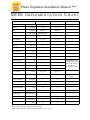
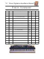
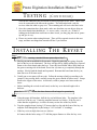
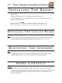
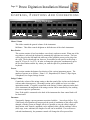
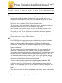
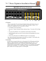
Presto Digitation
Installation Manual
QRS
Music Technologies,
Inc.Page 1
Presto Digitation Installation Manual
Installation and Owners Manual
QRS # 73200
Presto Your Old Acoustic Piano
Is Now
A Digital Piano
Keep the family heirloom looking & playing great.
Date: 09/04/01
Rev. 2.0
•
For go the expense of rebuilding a mechanical action
•
Make the piano lighter
•
Never let it go out of tune
•
Full MIDI compatibility
Page 2
Presto Digitation Installation Manual
TABLE OF CONTENTS
General Precautions ............................................................................................................ 2
MIDI Implementation Chart ............................................................................................. 3
Parts Summary .................................................................................................................... 4
Specifications ....................................................................................................................... 5
Tools Required .................................................................................................................... 5
Installation Guidelines - Preparation................................................................................ 6
Installation Guidelines - Testing Prior To Install ......................................................... 6,7
Installation Guidelines - Installing The Key Set ........................................................... 7,8
Installation Guidelines - Mounting Circuit Boards, Speakers, Pedals .......................... 8
Installation Guidelines - Mounting the Jack Panels ........................................................ 9
Description Of Controls, Functions And Connections .............................................10-12
MIDI Functions ............................................................................................................13-15
G ENERAL P RECAUTIONS
•
Avoid prolonged exposure of the equipment to direct sunlight or to excessively humid or
dusty atmospheres
•
Do not allow objects of liquids of any kind to penetrate the unit's casing.
•
Do not use solvents to clean the device as they may damage the plastic parts or paint finish
•
Always handle the device carefully during transit.
•
Do not apply excessive force to the connectors, switches or control knobs.
•
Do not position the device next to other appliances that generate strong radio interference.
•
Always check that the main voltage is correct for the device before plugging in. For any
fault or malfunction, contact your local retailer or an authorized electrical engineer.
Presto Digitation Installation Manual
Page 3
MIDI IMPLEMENTATION CHART
Function
Basic
Channel
Mode
Transmitted
Recognized
Remarks
Default
1
1
Can't be stored
Changed
1 - 16
1 - 16
Default
Mode 3
Mode 3
Messages
Omni Off, Poly
Altered
Note Number
15 - 113
True Voice
Velocity
After Touch B
15 - 113
Note On
0
0
Note Off
X
X
Key's
X
X
Ch's
X
X
X
X
64
0
0
66
0
0
67
0
0
others
*1
X
True #
*(0 - 127)
*(0 - 127)
0
0
Song Pos
X
X
Song Selection
x
x
Tune
x
x
Clock
X
X
Commands
x
x
Local ON/OFF
X
X
All Notes Off
0
0
Active Sense
0
0
Reset
X
X
Pitch Bender
Control Chang
Prog. Change
System Exclusive
System Common
System Real Time
Aux Messages
9 - 118
Notes: *Only with MIDI Function
Mode 1: Omni On, Poly Mode 2: Omni on, Mono
Mode 3: Omni Off, Poly Mode 4: Omni Off, Mono 0: Yes X: No
Control Changes are
programmable on each
foot pedal switches
64: Hold; 66:
Sostenuto; 67: Soft
Complete control of
effects
Page 4
Presto Digitation Installation Manual
PARTS S UMMARY
QRS Part
#
Item
73200
Description
For Use
With
QTY
U/M
1
EA
4
EA
Speaker
16
EA
Slide Tray
5
EA
Full Kit
1
Speaker Brackets 1 x 1 x 3
2
# 10 x 5/8 Pan Head Sm. Phillips
3
#6 x 1/2 Pan Head Phillips
4
#6 Washer
Key Set
16
EA
5
#8 x 1-1/4 Sm. Phillips
Key Set
16
EA
6
#6 x 1/2 Pan Head Phillips
4
EA
7
#6 x 1/2 Pan Head Phillips
8
EA
8
#6 x 1/2 Pan Head Phillips
Circuit
Board
MIDI
Controls
AC Plate
4
EA
9
#6 x 1/2 Pan Head Phillips
4
EA
10
Cable Clamp
Pedal
Contacts
Cable
Clamps
4
EA
11
Cardboard Drill Template
4
EA
12
Key set (88 notes)
1
EA
13
Speakers
1
EA
14
Power Cord
2
EA
15
Circuit Board Assembly
1
EA
16
Control Panel
1
EA
Presto Digitation Installation Manual
Page 5
SPECIFICATIONS
Presto Digitation - Specifications
Keyboard
88 Keys
Max. Polyphony
64 Notes
Section
Presets/BAS/Effects
Presets
Piano 1, Piano 2, Piano 3, Electric Piano 1, Electric Piano 2, Vibes, Jazz
Organ, Strings.
Controls
Master Volume, Brilliance, String Volume, Pitch, Parameter,
Transposer, Dyn Sensitivity, MIDI, Three Demos.
Connections
AC Input, Input L/R, Output L/R, MIDI In-Out-Thru, headphone,
Strings Volume, To pedals
Pedals
3
Speakers
2 Tweeters, 2 Midrange 100mm., 2 Woofers 160mm
Power Amp
35+35 Watts Stereo
Power Requirements
Ca. 117V, Ca. 220V or 240V
Power
200 VA.
Keyboard Width
51-3/16"
Keyboard Depth Front to Back
17.5"
Keyboard Height From Bottom of the
keybed to the top of the white keys
2.75"
Keyboard Height From the bottom of
the keybed to the bottom of the white
keys.
1-3/16"
TOOLS REQUIRED
Item
Item
Drill
3/16" Drill Bit
Paper and Pencil
1-1/2" Paddle Bit
6" Ruler Metric and English
Hack Saw (for shorter than 88 note installs)
Phillips Head and Standard Head Screw Driver
Pliers
Exacto Knife and or Scissors
Page 6
Presto Digitation Installation Manual
PREPARATION
Step 1
Remove the old action and discard
Step 2
Remove keys from key frame and discard. (At this time it will be necessary to remove
the mice nest, being careful that there are not any still residing there.)
Step 3
Before running the sweeper on the key frame, check for old coins. (This is my favorite
part!)
Step 4
Remove key frame from keybed.
Note: Now is the time to refinish the case if desired.
TESTING
Step 5
a. Before installing the Presto-Digitation Kit, it is highly recommended that you
perform a bench test. This will ensure that the unit works properly and was not
damaged during shipping
b. Begin by unpacking the kit and comparing the parts with those listed on the check
list. Be very careful when handling the unit, especially the cables and wire harnesses
c. To connect the key set to the Circuit Board (#192122), place the key set on a bench
or table with the key tops up. Then carefully tilt the key set up so that it is resting on
the fronts of the keys. Do not leave it unattended in this position. This offers a good
view of the circuit boards located under the keys. You will notice two open red
rectangular connectors. The two loose ribbon cables coming from the Circuit Board
are to be connected here
d. If you examine this Circuit Board closely, you will notice that these ribbon cables
are connected at CONN 11 and CONN 12. Take the ribbon connected at CONN 11
and place it on the key set circuit board connector closest to the base end of the key
set. It is also important at this point to note that one side of the ribbon cable has a
red wire. This should also be on the bass end of the key set when it is connected.
Repeat this with the remaining cable and the keyboard will be connected properly
e. The speakers will now need to be connected. Find the circuit board with the large
black heat sink. You will notice that at CONN 12 there is a connector with a group
of four wires coming out of it. The board has been labeled with an "R" and an "L"
signifying the right and left channels of the amplifier. If you follow the four wires
Presto Digitation Installation Manual
TESTING
Page 7
( C O N T I N U E D)
out from the connector, they will break off into tow groups of two wires. These wires
are to be connected to the tabs on the speakers. The tab marked with a red dot
receives either the white or gray wire. The remaining tab will receive the black wire.
f. Once the connections have been made, make sure that there are not objects lying on
the circuit boards that shouldn't be , i.e. screws, tools, a car jack, etc. If there is
nothing on the boards that could cause a short circuit, you may plug the unit in, power
up and give it a try.
g. Please use caution when testing this unit. There will be exposed circuits in this test
stage, and there are things that can and will bite if you let them.
INSTALLING THE KEYSET
Step 6
Note: If you are restoring a standard 88-note piano skip to Step 7
a. The key set can be modified for fewer notes. Begin by removing the springs from the
back of the keys to be eliminated. The keys will pop off by lightly pulling keys forward.
Remove the circuit board under the keys. Score the circuit board with a utility knife on
the green or tracing side of the board. Score four (4) times to go completely through the
tracings. Slowly bend the board until separated. Remount the board onto the key set,
then test to see if all notes work.
b. Usually one or two notes will not work. Follow the tracing to find keys needing to be
jumped. Using a utility knife, carefully scrape the green varnish off those traces. Scrape
down to the copper of the traces. At this time, solder a jumper wire between the two
traces.
c. Before installing the revised circuit board, cut the key set to desired length with a
hacksaw
Note: In shortening a key set, the demo feature will no longer be operational.
Step 7
a. Using the paper drill template, drill the key set hold-down holes. The template is the
exact size of the key set. Center the template between key blocks. If the key set is
wider than the original keys, it will be necessary to trim one of the key blocks.
b. Tape the templa te down leaving 1/8" between the key slip and the front of the key set
template. Drill through the keybed using a 3/16" bit at the "x" markings.
c. If the key set is too high, there are two choices:
d.Counter sink the holes using a 1/2" drill the proper distance to allow the key set to
Page 8
Presto Digitation Installation Manual
INSTALLING THE KEYSET
align evenly
Example: If the key set is 1/4" too high, counter sink the holes 1/4".
Cut off the plastic key set post using a hacksaw. Example: If the key set is 1/4" too
high, cut 1/4" off the post.
Note: If the key set is too low, use shims or washers to raise the key set.
M OUNTING T HE C IRCUIT B OARD
Step 8
The necessary circuit boards, amplifier and transformer are mounted onto one wooden
board. Install this to the keybed behind the key set using four (4), 1-1/2" screw.
M OUNTING T HE S PEAKERS
Step 9
The two speaker boxes each contain one midrange and one woofer. These can be
mounted anywhere above or below the keybed or on the back of the piano
P EDAL C ONTACTS
Step 10
Extend the cord out of the jack panel, down to the pedals. Using the original pedals,
mount the pedal contacts under the soft and sustain pedals only, using the yellow contact
for the sustain pedal and the green contact for the soft pedal. Adjust contacts up or
down for sensitivity.
Presto Digitation Installation Manual
Page 9
MOUNTING THE JACK PANELS
Step 11
The jack panels are intended to be mounted under the keybed for easy access using four
(4), 3/4" screws in each panel.
Jack Panel 1 includes: Headphones - Out
Line Out - Left & Right
Input - Left & Right
Jack Panel 2 includes: MIDI - In
MIDI - Out
MIDI - Through
Foot Pedal
P LAYING A DEMO
To play a Demo hold down the demo button and push the first key on the keyboards bass end.
Page 10
Presto Digitation Installation Manual
CONTROLS, F UNCTIONS A ND C ONNECTIONS
El. Bass
Piano 1
Ac. Bass
Piano 2
El. Piano 1 El. Piano 2
Min
Presto-Digitation
Piano 3
Harpsi
On/Off
Hall
Stage
Room
Pipe
Vibes
Strings
Chorus
Flanger
Tremolo
Max Mellow
Master Volume
Bright
Brilliance
Min
Ambience Transposer
Rotary
Dyn Sens
Demo
MIDI
Max Min
Strings Volume
Max
Effects Parameters
Master Volume
This slider controls the general volume of the instrument.
Brilliance: This slider controls brightens or dulls the tone of the whole instrument.
Bass Section:
This section consists of two bass timbres: one electric, and one acoustic. When one of the
two timbres is selected, the keyboard is automatically split into two sections. The bass
will be played on the left-hand side while any of the available presets can be played on
the right. The keyboard split can, however, be modified to suit specific needs along a
range of 35 keys (A-1 to G-2). In order to change the split point, simultaneously press
the two bass buttons and the key where you want the split to be positioned on the
keyboard.
Presets
This section contains the buttons for selectio n of the various instrument presets. The
number of presets are as follows: Piano 1-2-3, Harpsichord, El. Piano 1,2 Pipe Organ,
Vibraphone, Jazz Organ, Strings Section.
Strings Volume
Controls the volume of the strings setting so that the sound of the vio lins can be balanced
with any other chosen preset. - the strings section can be added as a layer over other
instruments sounds. If a pedal is connected to the Strings Volume connector on the back
of the instrument, the amplitude of the strings section can be controlled by foot, making
for a more expressive performance.
Note: If the pedal is connected to the back of the instrument the from control knob will
be deactivated.
Parameter
Temporarily changes a preset parameter associated with the last selected effect. E.g.,
if the Rotary effect button was last pressed, the speed of modulation of this effect can be
changed; with the Chorus or Flanger effects it is possible to vary the effect's depth of
intervention; with Tremolo, amplitude can be adjusted while with the ambience effects
(hall, stage, room, ambience) the length of reverb can be modified. If two effects are
selected simultaneously, the parameter control will change the effect pressed last.
Presto Digitation Installation Manual
Page 11
CONTROLS, F UNCTIONS A ND C ONNECTIONS
Effects:
Each button on this section is associated with a different effect. The effects
automatically exclude one another if located on the same row, while they can be
combined to a maximum of two if one effect is selected from the top row and another
from the bottom row.
Hall, Stage, Room, Ambience, Chorus, Flanger, Tremolo, Rotary.
The effects can be freely associated with the various presets. The only exception is the
Rotary effect which can only be selected for the Jazz Organ preset.
Note: When the Rotary effect is selected, the pedal that normally performs the soft
function now performs the rotary slow/fast function, switching from a slow to fast rotary
effect, and vice versa. The two speeds can be regulated by means of the parameter
control knob.
The effects section of Presto- Digitation have two buttons, designated as Reverb and
Chorus, which turn the relative effects on and off.
MIDI
Press MIDI: These three connectors are used to make the various types of connection
with other MIDI devices. The MIDI or Musical Instrument Digital Interface, is a musical
interface or language which enables instruments of different types and brand to
communicate. In other words, all instruments equipped with this device are able to
generate and receive digital messages which are interpreted and processed by the other
connected instruments.
The most common types of information transmitted are: the note generated by the
instrument. Its duration and the force or speed at which it is played; the number
corresponding to the selected sound on the instrument (PG); the signal indicating whether
any particular pedal or control has been used by the transmitting unit (CC), and so on.
The instruments communicate by means of a cable with a 5-pole connector, although
there are only three wires connected inside. The connectors generally used by MIDI
instruments have the following designations and functions:
A number of devices may be connected up, remembering however that the MIDI
transmits its messages on 16 different channels. Therefore, if the devices are each set to
a different channel, they will respond only to the data transmitted on that particular
channel. If two instruments receive a note, for example on the same channel they will
play it simultaneously. Will depend on the impedance and the amplitude of the input
signal.
Note: The input level is not affected by adjustment of the Master Volume control on the
panel.
Pitch
This rod can be moved to adjust the pitch of the whole instrument.
Page 12
Presto Digitation Installation Manual
CONTROLS, F UNCTIONS A ND C ONNECTIONS
STRINGS
MIDI IN MIDI OUT MIDI THRU
VOLUME
PITCH
In:
Receives MIDI messages which can then be processed by the instrument;
Out;
Transmits MIDI messages generated by the instrument, such as notes and dynamics,
pedal controls, etc.
THRU:
This is a bridge connector. The messages received at MIDI IN are retransmitted without
altering them in any way through this connector. It is usually used to make bridge
connections between a number of units.
L (Mono)
R (Mono)
Input
L (Mono)
R (Mono)
Headphones
Output
Input L/R
Various types of equipment can be connected up to these inputs, such as tape recorders,
microphones or other instruments without independent amplification. The sound output
will depend on the impedance and the amplitude of the input signal.
Note: The input level is not affected by adjustment of the Master Volume control on the
panel.
Output L/R
The instrument's signal is emitted from these outputs and can be connected to an external
PA. The typical output level is about 0 db.
Headphones
Stereo headphones can be plugged into this socket. Another of these sockets is located on
the left, under the keyboard.
Presto Digitation Installation Manual
Page 13
MIDI FUNCTIONS
El. Bass
Piano 1
Ac. Bass
Piano 2
El. Piano 1 El. Piano 2
Min
Presto-Digitation
Piano 3
Harpsi
On/Off
Hall
Stage
Room
Pipe
Vibes
Strings
Chorus
Flanger
Tremolo
Max Mellow
Master Volume
Bright
Min
Brilliance
Ambience Transposer
Rotary
MIDI
Max Min
Strings Volume
TX
Dyn Sens
Demo
RX
Max
Effects Parameters
PG
CC
MODE
MIDI
MIDI
By pressing the MIDI button, we can edit the various MIDI functions, starting with
selection of the communication channels for receiving (rx) and transmitting (tx) data.
TX/RX Function
Operation is simple: Press Receive or Transmit, depending on whether you want to
select a channel for receiving or transmitting data. The relative LED will light up. At
this point, give the channel a number by pressing the appropriate key on the keyboard,
referring to the number markings.
Note: If the button marked OMNI ON is pressed, the instrument can receive on any
channel. If the OFF button is pressed, it doesn't transmit or receive any MIDI
information
PG Function
With this button, a program change code can be manually sent to one of the external
unit's regardless of the mode set-up status explained below. The procedure is similar to
the above. Each key is assigned a program change number, so to send PG No. 4, for
example, we have to press (in this order):
-MIDI button (To enter MIDI Edit.)
-PG button (The LED will light up.)
-The first C on the left of the keyboard, which is the fourth key and corresponds to PG
No. 4 (At this stage the PG LED will go out, confirming that selection has been made.)
If we are satisfied with the selected sound, we press the MIDI button again to exit
Editing and return to Play. If not we repeat the same operations in the above order to
select another program change.
Page 14
Presto Digitation Installation Manual
MIDI FUNCTIONS
El. Bass
Ac. Bass
Piano 1
Piano 2
El. Piano 1 El. Piano 2
Min
Presto-Digitation
Piano 3
Harpsi
On/Off
Hall
Stage
Room
Pipe
Vibes
Strings
Chorus
Flanger
Tremolo
Max Mellow
Master Volume
Bright
Min
Brilliance
Ambience Transposer
Rotary
MIDI
Max Min
Strings Volume
TX
Dyn Sens
Demo
RX
Max
Effects Parameters
PG
CC
MODE
MIDI
CC Function
The top version of the SV series features this handy function which allows the user to
assign a control change code to any of the pedals (soft, sustaining or damper). The
procedure for assigning the code to the pedal is as follows:
•
Press MIDI to enter programming
•
Press the CC button, associated with the ambience button. The relative LED will light
up.
•
Now press the pedal that is to be assigned the control change code number.
•
While holding the pedal, press the key on the keyboard corresponding to the chosen
CC number.
•
Release the pedal and press the MIDI button again to exit programming.
Now, whever the pedal is pressed, both its own code (e.g., damper -CC64) and the code
assigned through programming will be transmitted.
Local On/Off
If all the effects are turned off, the device will go into LOCAL OFF mode and will then
operate as a master-keyboard. It will transmit all MIDI messages (PG, CH, CC, etc.)
without emitting any form of sound. If desired, the internal sound module can be
controlled from an external master (Computer, Sequencer, etc.), placing all of the internal
sounds at the user's disposal. To exit this function, simply call up any sound from the
panel, and the device will again operate as a normal piano.
Presto Digitation Installation Manual
Page 15
MIDI FUNCTIONS
El. Bass
Ac. Bass
Piano 1
Piano 2
El. Piano 1 El. Piano 2
Min
Presto-Digitation
Piano 3
Harpsi
On/Off
Hall
Stage
Room
Pipe
Vibes
Strings
Chorus
Flanger
Tremolo
Max Mellow
Master Volume
Bright
Min
Brilliance
Ambience Transposer
Rotary
MIDI
Max Min
Strings Volume
TX
Dyn Sens
Demo
RX
Max
Effects Parameters
PG
CC
MODE
MIDI
Mode Function
The SCV 200 series pianos can treat preset change codes (PG) in three ways
To access on of the three modes, proceed as follows
Mode 1:
This is the default mode; I.e., the instrument is automatically set to this mode when it is
turned on. In this mode, if a preset is changed during a performance, no PG code will
be sent to the MIDI Out connector, although a PG may still be sent form the keyboard
iusing the above procedure.
Mode 2:
To change to this mode, press the MIDI button then Dyn.Sens (The Dyn. Sens. LED
will light up on the keyboard to confirm selection.) Press the MIDI button again to exit
Programming and return to Play.
We are now in Mode 2. In this mode each time that a button in the presets section is
pressed, a specific PG will be associated with it an transmitted from the MIDI Out port.
If the piano receives one of the codes, it will automatically actua te the corresponding
preset.
Note: If we combine the strings with any other preset on the instrument, it will not be
possible to transmit or recognize this combination. To make this option possible, we
have to select Mode 3.
Mode 3:
The same procedure as before is followed, subsequently pressing MIDI then Dyn. Sens.
(mode) until the Transposer button LED lights up too. We then press the MIDI button
to exit Programming and return to Play. We are now in Mode 3 and the instrument will
send and be able to interpret PG codes also relating to combinations of presets and bass
settings with the strings section.
Page 16
Presto Digitation Installation Manual