1
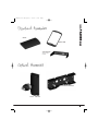
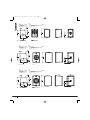
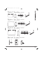
Di Manual 8-2-07 AW:Layout 1
21/2/07
10:51
Page 1
THE
RANGE
USER MANUAL
Di5, Di5t,
Di5 DC & Di5 DCt
Di6, Di6t,
Di6 DC & Di6 DCt
Di8 DC & Di8 DCt
Di Manual 8-2-07 AW:Layout 1
21/2/07
10:51
Page 2
3 INTRODUCTION
3 SAFETY INSTRUCTIONS
4 PRODUCT IDENTIFICATION
5 STANDARD AND OPTIONAL ACCESSORIES
6-9 INSTALLATION GUIDELINES
6
Installation using supplied yoke bracket
7
Installation using optional K-BallTM bracket
8
Installation using supplied yoke bracket with optional pole-mount adaptor
9
Installation using optional K-BallTM bracket with optional pole-mount adaptor
10 PRODUCT DIMENSIONS
11 HARDWARE DIMENSIONS
12-13 TECHNICAL SPECIFICATIONS
12 Di ICTTM specifications
13 Di Dual ConcentricTM specifications
14 PAINTING
14 WARRANTY STATEMENT
15 DECLARATION OF CONFORMITY
2
Di Manual 8-2-07 AW:Layout 1
21/2/07
10:51
Page 3
THE
For applications requiring extended low frequency enhancement, a range of Tannoy sub-bass systems are available and can
be used in conjunction with the Di.
RANGE USER MANUAL
Designed for a wide variety of sound reinforcement applications the Tannoy Di is an ultra compact loudspeaker system
capable of delivering high sound pressure levels with extremely low distortion, resulting in outstanding clarity, definition and
detail. A truly universal solution, the Di offers outstanding durability and resistance to scuffs and knocks. Able to deliver
consistent performance under a wide range of adverse conditions the Di is suited to applications indoors or out, whether it be
a theme bar or theme park. Available in black or white the Di will effectively blend into most backgrounds. Utilisation of the
point source loudspeaker allows the Di to be mounted on a wall or ceiling in either horizontal or vertical orientations without
affecting its performance. A range of hardware options ensures simple and effective installation. Also available with built in
line transformer.
1. Read these instructions.
2. Keep these instructions.
3. Heed all warnings.
4. Follow all instructions.
5. The user is responsible for fixing the hardware to the surface to ensure safe operation. The fixings must support the
weight of the product – please consult the manual’s specification page for the appropriate weights. Please consult the
relevant construction codes in your region for further information on suitable hardware fixing methods.
6. Some regional construction codes require the use of a secondary method of securing loudspeakers to surfaces to provide
security of a back-up support. A secondary support line should be attached from the safety loop on the rear of the product
to a source point on the wall. Please consult the relevant construction codes in your region.
7. Tannoy will not be held accountable for any damage caused by incorrect installation.
3
Di Manual 8-2-07 AW:Layout 1
21/2/07
10:51
Page 4
YOKE TRIM
Remove the yoke trims on the top
and bottom panels to access the
yoke bracket fixing point
GRILLE TRIM
Lift the grille trim back using the
tab to access the transformer
tapping switch on transformer
models.
GRILLE
INPUT CONNECTOR
Remove the rubber grommet to
access the connector. The
rubber grommet ensures the rear
of the product is kept water-tight
SAFETY TAB
4
Di Manual 8-2-07 AW:Layout 1
21/2/07
10:52
Page 5
THE
GRILLE TRIM
RANGE USER MANUAL
GRILLE
YOKE BRACKET
(SUPPLIED WITH
FIXINGS)
POLE MOUNT ADAPTOR
K-BALLTM BRACKET
5
Di Manual 8-2-07 AW:Layout 1
21/2/07
10:52
Page 6
USING SUPPLIED YOKE BRACKET
1. Fix the yoke bracket
to the surface using a
suitable fixing method.
2. Remove the yoke
trims from the product
to access the bracket
fixing points.
3. Remove the rubber
grommet from the rear of
the speaker. Inclusion of
the rubber grommet is
only required if installing
the product outdoors.
4. Feed the speaker
cable through the rubber
grommet then connect
the euro-type plug to the
wires, observing the
correct polarity.
5. For connection to the
loudspeaker, use pins
1 (+) and 2 (-).
6. Offer the speaker up
to the bracket and
attach it using a 5mm
alan key and supplied
fixings.
7. Connect the euro
plug then replace the
rubber grommet to
ensure the speaker is
watertight.
8. Connect a secondary
support line to the
safety tab at the rear of
the cabinet.
TRANSFORMER
MODELS ONLY
TRANSFORMER
MODELS ONLY
TRANSFORMER
MODELS ONLY
9. Lift the grille trim
using the tab to access
the rotary transformer
tapping switch. The
rotary switch is found on
the top of the Di5
models, and on the
bottom of the Di6 and
Di8 models.
10. The Di5t and Di5
DCt models are fitted
with 30W transformers.
11. The Di6t, Di6 DCt,
& Di8 DCt models are
fitted with 60W
transformers.
Pins 3 (-) and 4 (+) are
in parallel for connection
to additional speakers in
a distributed line.
Note: Even if pins 3 and
4 are not used, they
should be tightend to
prevent the screws from
vibrating.
6
THE SPEAKER IS SUPPLIED
IN LOW IMPEDANCE MODE.
NEVER CONNECT THE
SPEAKER TO A 70/100 VOLT
AMPLIFIER WHILE IT IS SET
FOR LOW IMPEDANCE.
THE SPEAKER IS SUPPLIED
IN LOW IMPEDANCE MODE.
NEVER CONNECT THE
SPEAKER TO A 70/100 VOLT
AMPLIFIER WHILE IT IS SET
FOR LOW IMPEDANCE.
Di Manual 8-2-07 AW:Layout 1
21/2/07
10:52
Page 7
THE
USING OPTIONAL K-BALLTM BRACKET
2. Connect the speaker
wires to the connector
block in the bracket.
For connection to an
amplifier use pins 1 (+)
and 2 (-)
Pins 3 (-) and 4 (+) are
in parallel for
connection to additional
speakers in a
distributed line.
3. If a conduit junction
box has been used,
offer the bracket up to
the adaptor plate, with
the foam gasket**
squeezed in between
the J-box and the wall.
Attach the bracket to
the surface using a
suitable fixing method*.
4. If you are attaching
the bracket directly to a
surface, offer the
bracket up to the
surface with the foam
gasket** squeezed in
between. Attach the
bracket to the surface
using a suitable fixing
method*.
5. Offer the speaker up
to the K-BallTM Bracket.
Push the speaker onto
the bracket to engage
the euro plug.
6. Fit the rubber
grommet and fingertighten the bracket bolt
while supporting the
speaker. If the
connector has engaged
properly the speaker
will lock onto the
bracket
7.Swivel the speaker
into position then use
a 19mm wrench to give
another 21/2 turns to
ensure the speaker is
locked in position.
8. Connect a secondary
support line to the
safety tab at the rear of
the cabinet.
TRANSFORMER
MODELS ONLY
TRANSFORMER
MODELS ONLY
TRANSFORMER
MODELS ONLY
9. Lift the grille trim
using the tab to access
the rotary transformer
tapping switch. The
rotary switch is found on
the top of the Di5
models, and on the
bottom of the Di6 and
Di8 models.
10. The Di5t and Di5
DCt models are fitted
with 30W transformers.
11. The Di6t, Di6 DCt,
& Di8 DCt models are
fitted with 60W
transformers.
THE SPEAKER IS SUPPLIED
IN LOW IMPEDANCE MODE.
NEVER CONNECT THE
SPEAKER TO A 70/100 VOLT
AMPLIFIER WHILE IT IS SET
FOR LOW IMPEDANCE.
RANGE USER MANUAL
1. If attaching the
K-BallTM bracket to a
flush mounted inwall
conduit junction box
(J-box), pass the
speaker wire through the
bracket adaptor plate
then attach the adaptor
plate to the J-box using
the fixings provided.
NOTE
* See safety notices on
page 3
** The foam gasket is
intended to provide a
water tight seal.
Inclusion of the foam
gasket is only a
requirement if
installing outdoors.
THE SPEAKER IS SUPPLIED
IN LOW IMPEDANCE MODE.
NEVER CONNECT THE
SPEAKER TO A 70/100 VOLT
AMPLIFIER WHILE IT IS SET
FOR LOW IMPEDANCE.
7
Di Manual 8-2-07 AW:Layout 1
21/2/07
10:52
Page 8
IUSING OPTIONAL POLE MOUNT ADAPTOR
IWITH SUPPLIED YOKE BRACKET
1. Use the supplied
fixings to fix the yoke
bracket to the pole
bracket adaptor.
Note that the Di5 models
require 2 fixing screws
whereas the Di6 and Di8
models require 4 fixing
screws.
5. Feed the speaker
cable through the rubber
grommet then connect
the euro-type plug to the
wires, observing the
correct polarity.
9. Connect a secondary
support line to the safety
tab at the rear of the
cabinet.
8
2. Fix the pole mount
bracket adaptor to the
pole using the strapping
provided. The bracket
can be mounted in
portrait or landscape
orientations.
3. Remove the yoke
trims from the product
to access the bracket
fixing points.
4. Remove the rubber
grommet from the rear
of the speake. Inclusion
of the rubber grommet is
only required if installing
the product outdoors.
6. For connection to the
loudspeaker, use pins 1
(+) and 2 (-)
7. Offer the speaker up
to the bracket and
attach it using a 5mm
alan key and supplied
fixings.
8. Connect the euro
plug then replace the
rubber grommet to
ensure the speaker is
watertight.
TRANSFORMER
MODELS ONLY
TRANSFORMER
MODELS ONLY
TRANSFORMER
MODELS ONLY
10. Lift the grille trim
using the tab to access
the rotary transformer
tapping switch. The
rotary switch is found
on the top of the Di5
models, and on the
bottom of the Di6 and
Di8 models.
11. The Di5t and Di5
DCt models are fitted
with 30W transformers.
12. The Di6t, Di6 DCt,
& Di8 DCt models are
fitted with 60W
transformers.
Pins 3 (-) and 4 (+) are
in parallel for connection
to additional speakers in
a distributed line.
Note: Even if pins 3 and
4 are not used, they
should be tightend to
prevent the screws
from vibrating.
THE SPEAKER IS SUPPLIED
IN LOW IMPEDANCE MODE.
NEVER CONNECT THE
SPEAKER TO A 70/100 VOLT
AMPLIFIER WHILE IT IS SET
FOR LOW IMPEDANCE.
THE SPEAKER IS SUPPLIED
IN LOW IMPEDANCE MODE.
NEVER CONNECT THE
SPEAKER TO A 70/100 VOLT
AMPLIFIER WHILE IT IS SET
FOR LOW IMPEDANCE.
Di Manual 8-2-07 AW:Layout 1
21/2/07
10:52
Page 9
THE
USING POLE MOUNT ADAPTOR
WITH OPTIONAL K-BALLTM BRACKET
2. Connect the speaker
wires to the connector
block in the rear of the
K-BallTM bracket.
For connection to an
amplifier use pins 1 (+)
and 2 (-).
Pins 3 (-) and 4 (+) are
in parallel for
connection to additional
speakers in a
distributed line.
3. Offer the K-BallTM
bracket up to the
adaptor plate, with the
foam gasket**
squeezed in between.
Use the supplied fixings
to fix the K-BallTM
bracket to the pole
bracket adaptor.
4. Fix the pole mount
bracket adaptor to the
pole using the strapping
provided. The bracket
can be mounted in
portrait or landscape
orientations.
RANGE USER MANUAL
1. Pass the speaker wire
through the pole-mount
adaptor plate then fix the
pole mount bracket
adaptor to the pole using
the strapping provided.
The bracket can be
mounted portrait or
landscape orientations.
TRANSFORMER
MODELS ONLY
5. Remove the rubber
grommet from the rear of
the speaker then offer
the speaker up to the
K-BallTM Bracket.
6. Finger-tighten the
bracket bolt to extend
the bracket out to
connect with the euro
plug socket. Position
speaker then use a
19mm wrench to give
another 21/2 turns to
ensure the speaker is
locked in position.
TRANSFORMER
MODELS ONLY
TRANSFORMER
MODELS ONLY
9. The Di5t and Di5 DCt
models are fitted with
30W transformers.
10. The Di6t, Di6 DCt,
& Di8 DCt models are
fitted with 60W
transformers.
THE SPEAKER IS SUPPLIED
IN LOW IMPEDANCE MODE.
NEVER CONNECT THE
SPEAKER TO A 70/100 VOLT
AMPLIFIER WHILE IT IS SET
FOR LOW IMPEDANCE.
7.Connect a secondary
support line to the
safety tab at the rear of
the cabinet.
8. Lift the grille trim
using the tab to access
the rotary transformer
tapping switch. The
rotary switch is found
on the top of the Di5
models, and on the
bottom of the Di6 and
Di8 models.
NOTE
** The foam gasket is
intended to provide a
water tight seal.
Inclusion of the foam
gasket is only a
requirement if
installing outdoors.
THE SPEAKER IS SUPPLIED
IN LOW IMPEDANCE MODE.
NEVER CONNECT THE
SPEAKER TO A 70/100 VOLT
AMPLIFIER WHILE IT IS SET
FOR LOW IMPEDANCE.
9
Di Manual 8-2-07 AW:Layout 1
21/2/07
10:52
Page 10
Di5
Di6
Di8
10
Di Manual 8-2-07 AW:Layout 1
21/2/07
10:52
Page 11
THE
5” YOKE BRACKET
85.0
[3.35"]
90.0
[3.54"]
123.0
[4.84"]
RANGE USER MANUAL
R15.0
[R0.59"]
241.0
[9.49"]
6.0
[0.24"]
35.0
[1.38"]
?22.0
[?0.87"]
54.0
[2.13"]
6” YOKE BRACKET
R15.0
[R0.59"]
[2.56"]
358.0
[14.09"]
145.0
[5.71"]
150.0
[5.91"]
180.0
[7.09"]
35.0
[1.38"]
65.0
[2.56"]
6.0
[0.24"]
Di6 YOKE
Di6 YOKE
Di6 YOKE
Di6 YOKE
?22.0
[?0.87"]
8” YOKE BRACKET
406.0
[15.98"]
R15.0
[R0.59"]
165.0
[6.50"]
170.0
[6.69"]
217.0
[8.54"]
35.0
[1.38"]
165.0
R11.0
[R0.43"]
[
70.0
[2.76"]
170.0
K-BALLTM BRACKET
93.2
[3.67"]
Di8
Di8YOKE
YOKE
Di8 YOKE
Di8 YOKE
47.7
[1.88"]
155.0
[6.10"]
137.9
[5.43"]
65.0
[2.56"]
11
Di Manual 8-2-07 AW:Layout 1
21/2/07
10:52
Page 12
ICTTM MODELS
Di5
Di6
Frequency Response (-3dB) (1)
90Hz - 25kHz
75Hz - 22kHz
Frequency Range (-10dB) (1)
80Hz - 30kHz
55Hz - 24kHz
System Sensitivity (1W @1m) (2)
1W = 2.45V for 6 Ohms
88dB
90dB
Dispersion
Degrees conical -6dB
90
90
Low Frequency Driver
Mineral loaded polypropylene
1x 110mm (4.50”)
1x 165mm (6.50”)
High Frequency Driver
ICT
ICT
Crossover
Inductively Coupled ICT™
7kHz
7kHz
SYSTEM
TM
TM
Directivity Factor (Q)
1kHz to 10kHz
5.3 averaged
10.5 averaged
Directivity Index (DI)
1kHz to 10kHz
6.6 averaged
8.4 averaged
Rated Maximum SPL (2)
Average
Peak
105dB
111dB
107dB
113dB
Power Handling
Average
Programme
Peak
50W
100W
200W
60W
120W
240W
Recommended Amplifier Power
100W @ 6 Ohms
120W @ 6 Ohms
Nominal Impedance
6 Ohms
6 Ohms
Distortion 10% Full Power
250Hz
1kHz
10kHz
(5.5V) 2nd Harmonic 3rd Harmonic
2.00%
0.26%
0.53%
0.19%
2.50%
0.35%
(6.0V) 2nd Harmonic 3rd Harmonic
1.86%
0.12%
1.17%
0.54%
1.10%
0.04%
Distortion 1% Full Power
250Hz
1kHz
10kHz
(1.73V) 2nd Harmonic 3rd Harmonic
0.65%
0.09%
0.144%
0.11%
0.52%
0.298%
(1.9V) 2nd Harmonic 3rd Harmonic
0.70%
0.14%
0.45%
0.39%
0.25%
0.065%
CONSTRUCTION
Enclosure
Weather resistant high impact polystyrene (HIPS), IP64 to EN60529 (IEC529)
Grille
Steel, with weather resistant coating
Finish
Textured black or white paint with matching rubber trims
Factory fitted custom trim colours available to special order
Connectors
Removable locking Euroblock type connector
with screw terminals and "loop through" facility
Fittings
1 x socket for K-Ball™ bracket and 2 x M8 yoke bracket inserts
Supplied Accessory
Yoke bracket
Dimensions
240.7 x 155.0 x 162.0mm
9.47 x 6.10 x 6.38”
2.2kg (4.85lbs)
357.5 x 230.0 x 223.2mm
14.08 x 9.05 x 8.79”
3.7kg (8.15lbs)
Di5t
Di6t
70V
30W / 15W / 7.5W / 3.75W / OFF
& Low Impedance operation
60W / 30W / 15W / 7.5W / OFF
& Low Impedance operation
100V
30W / 15W / 7.5W / OFF &
Low Impedance operation
60W / 30W /15W / OFF &
Low Impedance operation
Average
103dB (using 30W transformer tap)
107dB (using 60W transformer tap)
2.7kg (5.94lbs)
5.0kg (11.02lbs)
Weight
TRANSFORMER VERSIONS
Specifications as above except:
Transformer Taps
Rotary switch
mounted under trim
* Rated Maximum SPL (2)
Weight
*
See Passive models above for max SPL figures on low impedance settings.
Notes:
(1) Average over stated bandwidth. Measured at 1 metre on axis in an anechoic chamber
(2) Unweighted pink noise input, measured at 1 metre in an anechoic chamber
A full range of measurements, performance data, and EaseTM Data can be downloaded from www.tannoy.com
Tannoy operates a policy of continuous research and development. The introduction of new materials or manufacturing methods will always equal or exceed the published specifications,
which Tannoy reserves the right to alter without prior notice.
12
Di Manual 8-2-07 AW:Layout 1
21/2/07
10:52
Page 13
THE
DUAL CONCENTRICTM MODELS
Di5 DC
Di6 DC
Di8 DC
SYSTEM
90Hz - 50kHz
75Hz - 30kHz
65Hz - 30kHz
80Hz - 54kHz
55Hz - 35kHz
53Hz - 35kHz
System Sensitivity (1W @1m) (2) 88dB
1W = 2.83V for 8 Ohms
89dB
91dB
Dispersion
Degrees conical -6dB
90
90
90
Low Frequency Driver
Dual ConcentricTM constant directivity driver
with a resin treated multi fibre paper pulp cone
1x 110mm (4.50”)
1x 165mm (6.50”)
1x 200mm (8.00”)
High Frequency Driver
titanium dome with neodymium magnet system
19mm (0.75”)
25mm (1.00”)
25mm (1.00”)
Crossover
2kHz - 2nd order LF,
2nd order HF with
Dynamic HF protection
1.6kHz - 2nd order LF,
2nd order HF with
Dynamic HF protection
1.5kHz - 2nd order LF,
2nd order HF with
Dynamic HF protection
Directivity Factor (Q)
1kHz to 10kHz
5.3 averaged
5.6 averaged
5.5 averaged
Directivity Index (DI)
1kHz to 10kHz
6.6 averaged
7.0 averaged
7.0 averaged
Rated Maximum SPL (2)
Average
Peak
106dB
112dB
109dB
115dB
111dB
117dB
Power Handling
Average
Programme
Peak
60W
120W
240W
90W
180W
360W
90W
180W
360W
Recommended Amplifier Power
120W @ 8 Ohms
180W @ 8 Ohms
180W @ 8 Ohms
Nominal Impedance
8 Ohms
8 Ohms
Distortion 10% Full Power
250Hz
1kHz
10kHz
(6.9V) 2nd Harmonic 3rd Harmonic
4.00%
0.20%
0.76%
0.60%
0.65%
0.15%
Distortion 1% Full Power
250Hz
1kHz
10kHz
(2.2V) 2nd Harmonic 3rd Harmonic
2.00%
0.15%
0.009%
0.124%
0.32%
0.17%
(8.0V) 2nd Harmonic
1.00%
0.18%
1.00%
RANGE USER MANUAL
Frequency Response (-3dB) (1)
Frequency Range (-10dB) (1)
8 Ohms
3rd Harmonic
0.32%
0.32%
0.18%
(8.5V) 2nd Harmonic
1.55%
0.41%
1.20%
3rd Harmonic
0.42%
0.63%
0.65%
(2.5V) 2nd Harmonic 3rd Harmonic
0.25%
0.25%
0.06%
0.18%
0.45%
0.14%
(2.7V) 2nd Harmonic
0.43%
0.07%
0.55%
3rd Harmonic
0.48%
0.47%
0.13%
CONSTRUCTION
Enclosure
Weather resistant high impact polystyrene (HIPS), IP64 to EN60529 (IEC529)
Grille
Steel, with weather resistant coating
Finish
Textured black or white paint with matching rubber trims
Factory fitted custom trim colours available to special order
Connectors
Removable locking Euroblock type connector
with screw terminals and "loop through" facility
Fittings
1 x socket for K-Ball™ bracket and 2 x M8 yoke bracket inserts
Supplied Accessory
Yoke bracket
Dimensions
240.7 x 155.0 x 162.0mm
9.47 x 6.10 x 6.38”
2.2kg (4.85lbs)
357.5 x 230.0 x 223.2mm
14.08 x 9.05 x 8.79”
5.0kg (11.02lbs)
404.3 x 260.0 x 260.3mm
15.92 x 10.24 x 10.25”
6.0kg (13.23lbs)
Di5 DCt
Di6 DCt
Di8 DCt
70V
30W / 15W / 7.5W / 3.75W / OFF
& Low Impedance operation
60W / 30W / 15W / 7.5W / OFF
& Low Impedance operation
60W / 30W / 15W / 7.5W / OFF
& Low Impedance operation
100V
30W / 15W / 7.5W / OFF &
Low Impedance operation
60W / 30W / 15W / 7.5W / OFF
Low Impedance operation
60W / 30W / 15W / OFF &
Low Impedance operation
Average
106dB (103dB - 30W transformer tap)
109dB (107dB - 60W transformer tap)
111dB (109dB - 60W transformer tap)
2.7kg (5.95lbs)
5.5kg (12.12lbs)
7.0kg (15.87lbs)
Weight
TRANSFORMER VERSIONS
Specifications as above except:
Transformer Taps
Rotary switch
mounted under trim
* Rated Maximum SPL (2)
Weight
* See Passive models above for max SPL figures on low impedance settings.
Notes:
(1) Average over stated bandwidth. Measured at 1 metre on axis in an anechoic chamber
(2) Unweighted pink noise input, measured at 1 metre in an anechoic chamber
A full range of measurements, performance data, and EaseTM Data can be downloaded from www.tannoy.com
Tannoy operates a policy of continuous research and development. The introduction of new materials or manufacturing methods will always equal or exceed the published specifications,
which Tannoy reserves the right to alter without prior notice.
13
Di Manual 8-2-07 AW:Layout 1
21/2/07
10:52
Page 14
All Di products can be custom painted. If you choose to paint your product, the entire product should be spray painted with the
grille and grille trim still attached to the cabinet. Flexible vinyl paint should be used and care must be taken not to over apply
paint, especially to the grille.
No maintenance of the Di loudspeaker is necessary.
All of our products have been produced and tested with care and precision to give first-class service.
All passive components are guaranteed for a period of five years from the date of purchase from an authorised Tannoy dealer
subject to the absence or evidence of misuse, overload, or accidental damage.
All active and electronic components are guaranteed for a period of one year from the date of purchase from an authorised
Tannoy dealer subject to the absence of, or evidence of, misuse, overload or accidental damage.
If at any time during this warranty period the equipment proves to be defective for any reason other than accident, misuse,
neglect, unauthorised modification or fair wear and tear, we will repair any such manufacturing defect or, at our option, replace it
without charge for labour, parts or return carriage.
If you suspect a problem with a Tannoy product then, in the first instance, discuss it with your Tannoy dealer. If you require further
assistance then we ask that you deal directly with your local Tannoy distributor. If you cannot locate your distributor please contact
Customer Services, Tannoy Ltd at the address given below.
Customer Services, Tannoy Ltd., Rosehall Industrial Estate, Coatbridge, Strathclyde ML5 4TF, Scotland
Telephone:
Fax:
E-mail:
01236 420199
(National)
+44 1236 420199
(International)
01236 428230
(National)
+44 1236 428230
(International)
[email protected]
DO NOT SHIP ANY PRODUCT TO TANNOY WITHOUT PREVIOUS AUTHORISATION
Our policy commits us to incorporating improvements to our products through continuous research
and development. Please confirm current specifications for critical applications with your supplier.
14
Di Manual 8-2-07 AW:Layout 1
21/2/07
10:52
Page 15
THE
Details of the Apparatus:
Associated Technical File:
Applicable Standards:
Signed:
Position:
Date:
Tannoy Contractor Loudspeaker
Model Number: Di
EMCi6
EN 50081-1 Emission
EN 50082-1 Immunity
RANGE USER MANUAL
The following apparatus is manufactured in China for Tannoy Ltd of Rosehall Industrial Estate, Coatbridge, Scotland, ML5 4TF
and conform(s) to the protection requirements of the European Electromagnetic Compatibility Standards and Directives
relevant to Domestic Electrical Equipment. The apparatus is designed and constructed such that electromagnetic
disturbances generated do not exceed levels allowing radio and telecommunications equipment and other apparatus to
operate as intended, and, the apparatus has an adequate level of intrinsic immunity to electromagnetic disturbance to enable
operation as specified and intended.
Director of Engineering (Professional)
11th Dec. 06
15
Di Manual 8-2-07 AW:Layout 1
21/2/07
10:52
Page 16
REVISION DATE: 19 Feb ‘07
T: 00 44 (0) 1236 420199
T: 00 1 (519) 745 1158
T: 00 49 (180) 1111 881
T: 00 33 (0)1 7036 7473
E: [email protected]
E: [email protected]
E: [email protected]
E: [email protected]
Tannoy adopts a policy of continuous improvement and product specification is subject to change.
6481 0471 02/06
Tannoy United Kingdom
Tannoy North America
Tannoy Deutschland
Tannoy France