1
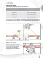
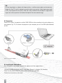
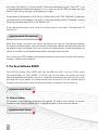
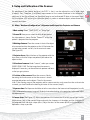
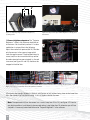
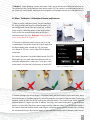
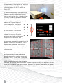
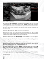
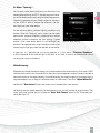
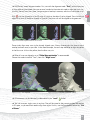
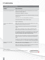
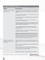
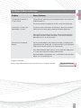
QUICK GUIDE
Contents
1. Introduction
1.1. Intended Purpose
1.2. Safety Instructions
1.3. Scope of Delivery
1.4. System Requirements
27
27
27
28
28
2. Initial Setup
2.1. Position of the Camera
2.2. Rotation of the Camera
2.3. Connection
2.4. Installing the Camera Driver
2.5. Setting up the Projector
2.6. Setting up the Projector as Extended Desktop in Windows
29
29
29
30
30
31
31
3. The Scan Software DAVID
3.1. Software Updates
32
32
4. Setup and Calibration of the Scanner
4.1. Menu ”Hardware Configuration“
4.2. Menu ”Calibration“
33
33
35
5. 3D Scanning
5.1. Menu ”Structured Light“
5.2. Menu ”Texturing“
37
37
39
6. Alignment and Fusion of Multiple Scans
6.1. Menu ”Shape Fusion“
6.2. Alignment of Multiple Scans
6.3. Fusion of Multiple Scans
40
40
40
42
7. Disposal / Recycling
43
8. Troubleshooting
8.1. Problems with the Scan Quality
8.2. Problems with Alignment / Fusion
8.3. Other Problems and Solutions
44
44
46
47
9. Terms of warranty
10. Copyright
11. CE Declaration of Conformity
48
48
49
26
1. Introduction
Thank you for choosing a DAVID product! In order to setup and run your 3D scanner safely, please read
the following safety instructions. This manual is part of this product. In case of passing this product,
please enclose this guide.
1.1. Intended Purpose
With your DAVID SLS-2 Structured-Light Scanner, you can quickly and accurately capture object surfaces three-dimensionally.
1.2. Safety Instructions
Place the appliance on a stable surface. Dropping the unit may
severely damage it, and the glass calibration panels may break.
Caution: Risk of cuts!
Do not place the device on a vibrating surface to prevent damage
of internal components and battery leakage.
Operate the device only in a dry environment.
Do not operate the device in potentially explosive atmospheres.
Never look directly into the projector lens when the lamp is turned on.
The bright light may cause serious damage to eyes.
Do not face the projector lens to the sun. It can result in fire.
Do not attempt to disassemble this projector. There are dangerous high voltages inside the unit.
Do not use the device if it is broken or has been dropped. In this case, contact your dealer
for inspection.
Stop using the device when there is smoke, unusual noise or smell. That could result in fire or
electric shock. In this case immediately disconnect the power plug, and contact your dealer.
Do not insert any objects into the openings of the projector chassis. That way you might come
into contact with dangerous voltage points or create a short circuit between the parts.
That could result in fire or electric shock.
Do not spill liquid of any kind onto or into the device.
27
The projector‘s power adapter is equipped with a three-wire grounded plug. The plug only fits
in a grounded power outlet. Make sure that the power outlet is properly grounded before
inserting the AC adapter plug. Do not insert the plug into a non-grounded socket. Please contact
your electrician for details.
Warnings! The grounding pin is a safety feature. Using a not properly grounded socket may
result in electric shock and/or injury.
Do not make any changes to any components.
Repairs to the device must be performed only by an authorized dealer or qualified service
personnel of DAVID Vision Systems GmbH.
Observe the safety instructions of the projector manufacturer. These can be found separately
on the accompanying ACER projector CD.
1.3. Scope of Delivery
• Structured-Light Scanner pre-assembled, consisting of:
– LED video projector
– Camera with lens
– Base rail with camera slide
• Tripod with protective bag
• Glass calibration panels + 2 fixing brackets 90°
• USB flash drive with DAVID-Laserscanner Pro Edition and camera drivers
• Projector Accessories
– External power supply and power cable
– Remote control
– Adapter VGA to Universal I/O
– VGA cable
– HDMI cable
– Protective bag
Technical changes are subject
– User Instructions
to change without prior notice.
• Adapter kit for power supply worldwide
• USB cable for camera
• Cable strap
1.4. System Requirements
• Windows XP, Vista, 7 or 8 (32-bit or 64-bit)
• Microsoft. NET Framework 4.0 (32-bit) or 4.5 (64-bit)
• 3D-capable graphics card
• Free VGA or HDMI port
• Two free USB ports
• Recommended: Dual-core processor, 2 GHz, Windows 7/8 64-bit, 8 GB RAM, NVIDIA
or AMD graphics card
28
2. Initial Setup
2.1. Position of the Camera
The camera can be mounted on the right or left side of the projector:
Size of the scan object /
scan area
Position of the Camera
(seen from rear)
up to 110 mm
to the left of the projector
110 to 350 mm
optional, better to the left
from 350 mm
to the right of the projector
If necessary, mount the camera slide to the corresponding side. The exact position of the slide (distance
from the projector) is set later in operation. The distance between the camera and projector optics will
be similar to the size of the object/region to be scanned.
Figure 2.1: Left: Small object Z short distances; Right: Large object Z greater distances
2.2. Rotation of the Camera
Rotate the camera by about 22° such that
it aims at the projection area. (Fig. 2.2)
To do this, loosen the thumbscrew under
the camera. Set the rotation angle by
means of the degree scale on the camera
slide, then fix the thumbscrew.
Figure 2.2: Setting the camera angle
29
TIP:
For very large objects, or objects with deep cavities, a smaller camera angle may be necessary.
Angles less than 20° result in reduced scan quality (noise, inaccuracies). A very large camera angle
(> 30°), may improve the scan quality a little, but is only suitable for very flat objects. Large camera
angles are usually impractical and reduce the depth of the measurement range.
2.3. Connection
Connect the camera, the projector and the DAVID USB flash drive according to the wiring diagram to
your computer (Fig. 2.3). To connect the projector to your computer, you can use HDMI (recommended)
or VGA.
Figure 2.3: Connection diagram
2.4. Installing the Camera Driver
Even if Windows installs drivers automatically, please install the supplied drivers:
1 Connect the USB flash drive to your PC, then select ”Browse“ or Explorer / My Computer.
2 Start ”Install_DAVID-CAM-3 M_Driver“ (administrator rights required).
3 Follow the instructions on the screen.
30
2.5. Setting up the Projector
The projector is already delivered with optimal settings, we recommend not to change anything in the menu.
Note: You can restore the recommended
settings in the projector‘s menu at any time
as follows (See Figure 2.4.)
1 Select ”Reset“
2 Turn the ”Auto Keystone ” off, and set the
manual value ”Manual Keystone“ to 0
3 As ”Projection Location“, select the icon
for desktop use, not ”AUTO“
Figure 2.4: Projector settings
Note: You can activate the ”Eco-Mode“ if you do not need the maximum intensity of light.
For details, please read the manual of the projector.
2.6. Setting up the Projector as Extended Desktop in Windows
Click the right mouse button on a blank area of your Windows desktop, select “Screen resolution“ or
”Properties“ (depending on your Windows version).
Figure 2.5: In this window you can separately configure your two ”Displays“, the monitor and the projector. (Image may vary)
31
Your screen should be set as ”primary monitor“. Make sure the projector (usually ”Acer K132“) is set
as extended desktop (”Extend these displays“). This is necessary so that DAVID can project the stripe
patterns, while the user interface is displayed on your screen.
The resolution of the projector must be set to its native value (usually 1280 * 800 pixels) Furthermore,
you should make sure the projector is set to 60 Hz. Choose the Projector and click ”Advanced“, here you
should set the refresh rate to 60 Hz in the ”Monitor“ tab.
A more detailed description can be found in our online manual in the section ”Structured Light 3D
Scanning“ on
http://www.david-3d.com/manual
When these settings are correct, your monitor and projector will show the same desktop wallpaper,
but otherwise different contents. You can move your mouse pointer sideways between the monitor and
the projector image. The Windows Start menu and most of the desktop icons are only displayed on the
monitor. Any window can be moved between monitor and projector back and forth.
So in case the main DAVID window is displayed on the projector, please grab its title bar with the mouse
and drag it sideways onto the monitor.
3. The Scan Software DAVID
Start DAVID by running ”Start_DAVID3_x64“ from the USB flash drive. If you use a 32-bit system
(not recommended), run ”Start_DAVID3“. On the left side, the main menus are stacked, and can be
individually opened and collapsed. Each menu is responsible for one work step, which you will usually
go through from top to bottom. This printed manual refers to version 3.10 of the software and may
already be out of date. Please follow the detailed and always up-dated on-line instructions at
http://www.david-3d.com
3.1. Software Updates
Our software is constantly being developed and improved. All updates within version 3.x are free.
Therefore use the automatic update feature, or download updates manually from our website:
http://www.david-3d.com
32
4. Setup and Calibration of the Scanner
An advantage of the modular design of the SLS-2 is that it can be adjusted to scan a wide range
of objects sizes. Therefore, a calibration (measurement of the scanner hardware in the software) is
necessary so that the software can then obtain precise and undistorted 3D data at the correct scale.
For this purpose, a 90° pair of glass calibration panels is used as a reference object, whose dimensions
are precisely known.
4.1. Menu ”Hardware Configuration“: Alignment and Setup of the Projector and Camera
1 Main setting: Select ”DAVID SLS-2“ as ”Setup Type“.
2 Screen ID: Here you can select on which display device
the stripe pattern is shown. Set the ”Screen ID“ so that the
pattern is projected from the projector.
3 Working distance: Place the scanner in front of the object
to be scanned and aim the projector so that it illuminates the
surface to be scanned - not less, but also not much more.
(See Figure 4.3)
4 Projector focus: Adjust the focus of the projector with the
focus lever, so that the stripes are perfectly focused on the
object surface.
5 Selection of camera: Under ”camera“, select your camera
(DAVID-CAM-3.1-M). The live image from the camera is
displayed. If necessary, set the mechanical aperture and focus
so that you get a picture.
6 Position of the camera: Move the camera slide by
Figure 4.1: ”Hardware Setup“ menu
loosening the thumbscrew so that the camera is aimed
on projected pattern on the object. Then fix the camera
slide. If the viewing range of the projector and/or camera contains much more than the surface to be
scanned, you should reduce the working distance of the scanner (step 3).
7 Exposure time: The Exposure should be set to the same value as the frame rate of the projector (usually
1/60s), otherwise the camera image will flicker/pulsate when looking at the projection. In this case adjust
the exposure time.
8 Camera focus (See Figure 4.2): Adjust the aperture of the camera (dial A) so that you will get a rather
bright picture. Look at the camera image and watch the sharpness of the object and the sharpness of
the projected black and white stripes (cross). Adjust the focus of the camera (dial B) so that the object is
depicted as sharp as possible.
33
C
B
A
Figure 4.2: Adjusting rings (A) aperture and (B) focus,
(C) fixing screws
9 Camera brightness/aperture: The ”Projector
Brightness“ slider in the software should be set
to maximum. You should only reduce it if a clean
modulation is not possible in the following.
Adjust the mechanical aperture (dial A). Consider
only those areas in the camera image which
show the regular waves! The displayed intensity
curves (red) must be sinusoidal and may neither
be undersaturated nor oversaturated, i.e. the red
sine curve (see Figure 4.4 and 4.5) should not be
cropped at the blue lines.
Figure 4.3: Setup of the object and arrangement of the projector
and camera
Figure 4.4: Typical live image with good setup and settings
Figure 4.5: Left: Too dark Z open aperture further; Middle: Well-controlled sine wave almost reaching the blue borders; Right: Too
bright, sine is cut-off (overdriven) Zclose the aperture somewhat
If the curves are strongly flattened in the dark area (bottom or left) without being close to the lower blue
lines, the ambient light may be too strong. In this case please darken the room.
Note: The aperture dial (A) on the camera has a scale (f-stop from 16 to 1.4), see Figure 4.2. Even for
very bright conditions (small objects), please avoid setting f-stop higher than 16, otherwise you will lose
sharpness. If necessary, better reduce the value ”Projector Brightness“ in the software.
34
10 Fasten all screws (projector, camera and camera slide), so that nothing can be displaced from now on.
The camera lens dials can be fixed with their locking screws (C). The scanner is now optimized for your object (size of the scanning area, working distance, brightness of the object) and must be calibrated like this.
4.2. Menu ”Calibration“: Calibration of Camera and Projector
1. Now set up the calibration corner. You will need both
90° fixing brackets and the glass calibration panels. Put
one fixing bracket flat on the used surface (e.g. a table).
Insert the glass calibration panels in the fixing bracket.
Finally, attach the second fixing bracket on the glass
calibration panels (Fig. 4.6). Attention: Please take note
of our safety advices in Chapter 1.2.
2. Choose the calibration pattern whose size fits to the
scanned object. The pattern should be slightly larger than
the object/region to be scanned (Fig 4.8). For object
sizes above ca. 200 mm, use the large 240-mm pattern
on the back.
Figure 4.6: Setting up the glass calibration panels
For starters, the pattern should be folded inwards (Fig. 4.8).
Advanced users can avoid undesired reflections with an
outwardly folded pattern if necessary. Fix the glass calibration panels using the two fixing brackets to exactly 90°.
Figure 4.7: ”Calibration“ menu
Figure 4.8: Calibration pattern too small
Suitable calibration pattern
Calibration pattern too large
3. Remove the object and set up the glass calibration panels and the scanner in front of each other, about
the same distance as the object previously, so that the projection and camera image are sharp. Camera and
projector should not look at a too flat angle at the calibration panels. The camera image should show the
projected pattern as large as possible. In addition, the 6-rings and several other points of the calibration
pattern must be visible. The entire camera image should be filled with about 15 to 70 calibration markers,
the camera should not be able to look aside the glass calibration panels. You can achieve this by moving
the scanner and tilting or adjusting the tripod, but you should not change anything above the red base rail.
35
4. Enter the correct scale length in the ”scale [mm]“
field. You can find it on the edge of the selected
calibration pattern. (30, 60, 120, or 240 - see
Figure 4.10)
5, Check the camera image: In the areas where
the waves are visible, the red intensity curves
must not reach the blue lines. If the object to be
scanned is considerably darker than the white
glass calibration panels, the sine waves will
now be overdriven. Correct this by temporarily
reducing the ”Projector Brightness“
slider in the software. The camera
image for calibration should look
similar like shown in Figure 4.11.
6, Click ”Calibrate“ to calibrate the
entire scanner. In this step, the
software first measures the position,
orientation, focal length and distortion
characteristics of the camera. Then,
a pattern sequence is projected in order
to measure the same optical characteristics of the
projector. If texturing is not turned off, finally a
white balance is performed. After successful
calibration, a checkerboard pattern is projected,
the corners of which should fall exactly into the
calibration points.
Figure 4.9: Typical setup for calibration
Figure 4.10: Entering the size of the calibration pattern
The scanner is now calibrated. This refers to the
position and rotation of camera and projector
according to each other, as well as focusing and
brightness settings. You can move, tilt and rotate
Figure 4.11: Ideal live camera image for calibration
the scanner as a whole, and you can close the
DAVID software and restart it without losing the
calibration. You can also change the value of ”Projector Brightness“ to adjust the brightness (red sine
curves) to the respective object to be scanned. However, if you rotate or move camera and projector
separately or adjust the focus (for example for scanning significantly larger or smaller objects),
the entire calibration process must be repeated.
36
5. 3D Scanning
5.1. Menu ”Structured Light“:
Z Place the scanner and the object in front of each other,
at the same distance as during setup and calibration. With
a wrong working distance, the camera image and projected
stripes would be blurred. If necessary, correct the distance
between object and scanner, but by no means change the
focus of camera or projector.
Important: Before each scan please check that the red sine
curves are not cropped / overdriven (relevant only in the areas
where the wave pattern is visible). If adjustment is necessary,
adjust the ”Projector Brightness“ in the software.
Z Select the pattern parameter ”Quality“, ”Default“ (recommended) or ”Speed“. This setting affects scan quality and
scan time.
Z With each click on ”Start“ a new scan is generated. A
sequence of patterns is successively projected and recorded.
This can take between settings 2-4 seconds or longer.
Figure 5.1: Menu ”Structured Light“
Figure 5.2: Typical camera image immediately before the scan
37
Figure 5.3: Display of the scan result in 3D
Z If you activate ”Auto. Grab Texture“, a color texture will be recorded with each scan. If the texture
is too bright or too dark, you can adjust its settings in the ”Texturing“ menu (see next sub-chapter).
You can toggle the visibility of the texture in the 3D view using the appropriate button under ”Visibility“.
Z Using the mouse, you can rotate the 3D view (right mouse button), move (left mouse button) and
zoom (mouse wheel).
Z With the ”Live“ button under ”View“ you can return to live video feed.
Z To assure that multiple scans of the same object can be well combined later, they must overlap
sufficiently. You usually will need about 6-8 scans all around the object, maybe plus some angular views
of top and bottom. Textures can help later when aligning multiple scans.
Z With the smoothing filters under ”Result Filtering“ you can smooth the 3D scan result manually.
However, we recommend not to do this (set filters to 0). If your scans are noisy or wavy, you should rather
optimize the scanning conditions (brightness settings, room conditions). More smoothing options are
available in the Shape Fusion menu later on.
Z The filter ”Quality check“ removes scan data that are likely to be inaccurate. This is possibly on
the edge of the scan or at transitions between light and dark areas. You can change the filter value and
see the effect immediately on the scan. The recommended value is 0.5.
Z Save each successful scan as an OBJ file (”Save As...“) and/or add it to the scan list (button ”Add
to List“)). After each click on ”Add to List“, you can align the new scan immediately to the previous
scans (Shape Fusion menu, see next chapter). Alternatively, you can first create further scans in the
”Structured Light“ menu, collect them in the list, and align them all later.
Z If the settings are optimized, and you do a lot of scans in a row, you can accelerate the workflow
with the ”Auto. Add to List“ and/or ”Align to Previous Scan“ options. This is recommended only
for experienced users.
38
5.2. Menu ”Texturing“:
You can grab a color texture with each scan. Because of the
monochrome camera of the SLS-2, the color texture of the object will be determined by measuring the reflective properties.
Therefor the projector pictures different colors on the object
surface. DAVID is able to interpret the reflections and converts them into a real color texture.
For the texture grabbing, different lighting conditions may
be ideal. When the ”Texturing“ menu is open, you can make
optimizations (projector brightness, exposure time, camera
properties) without influencing the scan settings. A good
texture is like a clear photo: evenly lit, not too bright, not
too dark. The projected color stripes should be visible in the
camera image as light gray stripes (not too dark, but not white).
Figure 5.4: Menu ”Texturing“
If necessary, it is advisable not to use the projector as a light source (”Projector Brightness“
to 0) but to provide diffuse ambient light in the room. In that case, of course, the monochrome camera
can only grab a gray-scale texture.
White Balancing:
Whenever you change the texture settings, you should re-perform the white balancing. That means DAVID
calibrates color transmission characteristics of the entire system (projector, camera), in order to be able to
measure the colors of the object correctly. For white balancing, the camera image must show exclusively a
large white object (such as the glass calibration panels or a white wall). Then click ”Adjust White Bal.“
Z With the ”Grab texture“ button, the current scan is provided with a new texture.
Z Settings here are stored separately. For the following scans, you will not have to go to the menu ”Texturing“ each time, instead you can activate the ”Auto. Grab Texture“ option in the ”Structured Light“
menu (See Figur 5.1).
39
6. Alignment and Fusion of Multiple Scans
6.1. Menu ”Shape Fusion“
This menu provides functions to 1. align and 2. fuse/merge
several scans into a single 360° model. The fused object
subsequently can be exported to various formats, to be used
e.g. for 3D printing.
In the following, we will describe the general case how to
fuse variously positioned scans. Notes on special cases and
more detailed information can be found on
http://www.david-3d.com/manual
6.2. Alignment of Multiple Scans
Figure 6.1: Menu ”Shape Fusion“
Z In general, the individual scans are collected via the ”Add to List“ button during scanning. You can
import more scans (OBJ) into the List of Scans - either by drag and drop from the Explorer, or using the
”+“ icon below the list.
Z In the list individual scans can be made visible/invisible by click on
.
Z If you want, you can clean up your scans with the ”cleaning“ tool. At this point, you should delete
only surface segments that are not helpful for the alignment, e.g. do not delete surfaces that multiple
scans have in common.
Z Using the buttons
you can arrange all scans side by side, to get a good overview.
Figure 6.2: Single scans prior to alignment, arbitrarily arranged
40
Z DAVID offers several alignment modes. First, start with the alignment mode ”Free“, which allows you
to align arbitrarily positioned scans one-on-one. In order for the automatic mode to align two scans successfully, the two scans must have a unique region of overlap in common, which must not be too small.
With
start the alignment. In the 3D view, first click on the object A to be aligned. Then click on the
object B, to which A should be aligned. In Figure 6.3, the blue scan will be aligned to the green one:
Figure 6.3: Automatic alignment with two mouse clicks
Successively align more scans to the already aligned scans. Always choose pairs that have as much
overlap (common areas) as possible. In the above example, the next step would be to align the yellow
to the blue scan: click on the yellow, then the blue scan, etc.
Z When all scans are aligned, a run of ”Global fine registration“ is recommended.
Choose that mode instead of ”Free“, then click ”Align scans“.
Figure 6.4: Scans after alignment
Figure 6.5: Fusion result (with ”close holes“ option)
Z All movements can be individually made undone by the ”undo“
button.
Z You can save your single scans at any time. They will be stored in their current position and rotation
in 3D space, so you would not need to align them again. For this, use the Save buttons below the ”List
of Scans“.
41
Z If the automatic alignment finds false solutions, you should activate ”Contact Pair Selection“ .
Then you can help DAVID by clicking on distinctive points that are to be aligned with each other (e.g.,
tip of the nose). Relevant here is the area within the red circle at the mouse pointer. If you would like
to define the contact pair points very precisely, zoom up close with the mouse wheel before you click. If
you want to mark the contact area only roughly, zoom out before you click.
Z After a few registration steps, it may be helpful to group two or more aligned scans temporarily.
Simply select two or more scans in the ”List of Scans“ (check the checkboxes of the respective scans),
click with the right mouse button and select ”Combine selected scans”. This allows you to group
scans (temporarily) and use them as if they were a single scan. In our example (Büssing bust, Figure 6.2)
we could combine scans 1 and 4 just before the alignment of the 5th. In this way, the 5th scan will be
aligned simultaneously to both, which can lead to more overlap and thus better results. To un-group,
click with the right mouse button on the entry in the list and select ”Uncombine scans”.
6.3. Fusion of Multiple Scans
Z Make all scans visible
, which you want to fuse. Invisible scans will not be included in the fusion.
Z First, try a small ”resolution“ value. High values cause to very long computing time and higher
memory usage.
Z The ”refinement“ option in some cases can improve the accuracy and sharpness, but it often
causes distortions. Feel free to try it, depending on the object.
Z Click on ”Fuse“ to start the fusion process. This is a computationally intensive process and will take
a few seconds to several minutes. The visible scans are merged to form a closed triangle mesh, holes
are (optionally) closed, smaller artifacts are removed, and if the scans have textures, a common texture
is generated. For example see Figure 6.5.
Z Finally, you can export your fused 3D object into an OBJ, STL or PLY file by using the ”Save“ button.
42
7. Disposal / Recycling
The electronic components of the DAVID 3D scanner, including disused batteries or accumulators, may
not be disposed of as household waste. Every consumer has a statutory obligation to properly dispose
of these items at officially designated points of disposal. In accordance with the EU Directive 2002/96/
EC on waste electrical and electronic equipment this must be disposed of in accordance with local regulations. You can dispose of the product at your local public point for collection of electronic waste. You
can also return the product to us for disposal. In that case, please use the following address:
DAVID Vision Systems GmbH
c/o RECYCLING
Rudolf-Diesel-Str. 2a
56070 Koblenz
Germany
Batteries containing hazardous substances are marked with the symbol of a crossed out wheelie bin.
Below that symbol the appropriate chemical name of the pollutant is given. The terms have the following
meanings:
Cd = battery contains cadmium
Pb = battery contains lead
Hg = battery contains mercury
43
8. Troubleshooting
8.1. Problems with the Scan Quality
Problem
Cause / Solutions
The scans are noisy (rough surfaces)
Adjust the camera aperture (f-stop) so that the red intensity curves are welladjusted and not being cropped. (*)
Set the projector‘s brightness to maximum.
Increase the camera angle (at least 20°) and the distance between the camera
and projector. (*)
Set the value ”Gain“ in the camera properties to minimum (*)
Select pattern parameter ”Default“ or better ”Quality“.
Reduce the ambient light.
The scans show a regular wave
pattern
Make sure that the red intensity curves are neither overdriven nor too weak.
Flattened sine waves cause waves in the scan. (*)
Reduce the ambient light. Avoid fluorescent lights and all flickering light
sources.
Make sure that in the projector‘s menu, all filters are adjusted to neutral
(default values) and no artificial contrast enhancement, etc. is active. (*)
On shiny objects, direct reflections of the light projector in the camera should
be avoided. The object must be matted with spray if necessary. We recommend our Coating Spray, order number: COATING-SPRAY-500
Make sure that the camera image does not flicker, meaning that the exposure
time of the camera fits to the frame rate of the projector (usually 60 Hz and
1/60s).
During the scan, nothing is allowed to move (scanner, object). A scanned person should lean against sth. as comfortably as possible, and hold their breath.
The scans show strip-shaped
distortions
Make sure that the resolution of the projector is set correct. It should be set to
the native resolution, usually 1280 * 800 pixels. (*)
Make sure in the projector‘s menu that the keystone correction is off: Set the
manual value to zero and deactivate the automatic. (*)
(*) Requires recalibration
Other possible problems and their solutions can be found on our website in the FAQ:
44
http://www.david-3d.com
8.1. Problems with the Scan Quality
Problem
Cause / Solutions
The scans are smooth / fine details
are missing
The shorter the distance between the scanner and the object, the more
detailed are the scans. Set up the scanner at the smallest possible working
distance, so that the scan size is just sufficient.
Make sure that the distance between scanner and object is the same as during
the calibration.
Make sure that both, projector and camera, are well focused on the scanned
object.
The scanner can capture only details that are not finer than 0.1% of the
scanned surface (min. 0.06 mm).
The scans contain irregular distortions / outliers
Make sure that the ambient light is constant.
Make sure that nothing moves in view of the camera, not far behind the object
as well.
Make sure that the object and scanner do not move.
On shiny objects reflections should be avoided. The object must be matted
with spray if necessary. We recommend our Coating Spray, order number:
COATING-SPRAY-500
Use a dark background / table cover, which reflects almost no light (e.g. black
fabric).
If outliers can not be avoided, you can remove them later in the Shape Fusion
menu (”Cleaning tool”). Often, the most comfortable way is to clean up all scans
at the same time before aligning them.
Small outliers will be automatically removed in the final processing step,
Fusion.
The color textures do not look good
Open the ”Texturing“ menu and perform a new white balance.
Other possible problems and their solutions can be found on our website in the FAQ:
http://www.david-3d.com
45
8.2. Problems with Alignment / Fusion
Problem
Cause / Solutions
Shape Fusion: The scans are aligned
completely wrong
DAVID aligns the scans such that the overlapping areas are maximized. That
maybe causes wrong solutions if there are more than one matching overlapping areas.
Start the alignment again. The algorithm is in part randomized and therefore it
can find another solution next time.
Use the ”Contact Pair Selection“ to define by mouse a pair of regions which
are supposed to overlap.
The scans should overlap at least about 30%. The more overlap there is, the
more likely the correct alignment is found.
If you have rotated the object only about the vertical axis (parallel to the axis of the
calibration corner) and if you have not tilted the scanner after calibration, you can
choose the ”Around Y-Axis“ alignment mode.
If you know the approximate angle of rotation between scans, enter it in the
”Rotation Angle“ field. Depending on the direction of rotation you may have to
enter a negative value.
If the object has color transitions or markings, take a texture with each scan,
and activate “Use Texture” when aligning.
In difficult cases, you can manually align the scans: Click on the scan to be
moved, then hold down the Ctrl key and move/rotate the scan with the mouse
(left/right mouse button). Release the Ctrl button temporarily to change your
viewing direction. With practice, this can be achieved quite quickly. When
you have reached an approximate alignment with some overlap, use the mode
”Pairwise fine registration“ in order to perfect your solution.
Shape Fusion: The alignment is
inaccurate / the scans do not match
exactly together
Make sure that your scans are not distorted. This can easily happen if something was changed on the scanner after calibration. Calibrate again in case of
doubt.
Create more scans, so that neighboring scans have more overlap and thus can
be aligned more precisely.
Make sure that all around, all scans are aligned very accurately to their
respective neighbors, otherwise an error is easily continued. Align a new scan
only when all previous scans are precisely aligned.
Especially for smooth objects, a texture can help to find a good alignment.
Other possible problems and their solutions can be found on our website in the FAQ:
46
http://www.david-3d.com
8.3. Weitere Probleme und Lösungen
Problem
Cause / Solutions
The exported 3D model has an
incorrect scaling
During calibration, make sure you have entered the correct scale value of the
calibration pattern. (*)
The unit of the 3D data corresponds to the unit of scale value (usually mm).
The resolution / file size of the
exported data is too high
Fuse the scans with a lower value in the ”Resolution“. But try not to re-import
and fuse your Fusion result again, instead fuse the original aligned scans.
Import your Fusion result into the List of Scans, click the entry with your right
mouse button and select ”Reduce mesh density.“ Then save it with the Save
button below the list – do not Fuse it again.
Software crash / unexpected
behavior
The most common problem is lack of memory. If possible, use a 64-bit system
and the 64-bit version ”DAVID_x64“. In 32-bit it can help to occasionally restart
DAVID and not work with too many scans simultaneously.
In the Advanced Settings under ”Service“, you can enable the ”Debug Console“. It may show some useful information about the error.
Report the problem to the developers, e.g., on the website in the forum ”Bug
Report“, if it is not known there yet.
(*) Requires recalibration
Other possible problems and their solutions can be found on our website in the FAQ:
http://www.david-3d.com
47
9. Warranty Terms
This device was manufactured using the latest production methods and has been carefully inspected.
All DAVID products are subjected to rigorous quality control. If this device nevertheless fails to perform
faultlessly, this is something we regret and we ask you to consult your supplier. The following conditions
apply to warranty claims:
This warranty is valid for a period of 24 months from the day of purchase. Please keep the receipt
carefully as proof of purchase when making a warranty claim.
The defective product may be returned to your supplier during the warranty period. If the warranty claim
is valid you will be entitled to the repair of your device or a new device will be given to you. This is free
of charge. Alternatively a warranty claim can be settled through reimbursement of the purchase price.
After the warranty period has expired you still have the option of sending the defective device to your
supplier or to the DAVID after-sales service for repair. Repairs made after expiry of warranty will be
subject to a charge. Your statutory rights are not affected through this warranty.
Damage caused through improper handling, use, storage, changes to the electronics, lens or housing, or
through Acts of God or other external influences or any operation outside of the technical specifications
are not covered by this warranty.
Before returning the device please contact your supplier to ensure your warranty claim is processed as
efficiently as possible. If it is not possible to process your warranty claim through your supplier, you may
as an exceptional case contact the DAVID after-sales service directly.
10. Copyright
All product names and trademarks mentioned here are only for identification purposes and are the
property of their respective owners.
48
11. CE Declaration of Conformity
DAVID Vision Systems GmbH
Rudolf-Diesel-Str. 2a
56070 Koblenz
Germany
hereby declares under sole responsibility that the product DAVID-SLS-2 is in conformity with the following standards or standardized documents:
USB flash drive:
EN 55022:2010
EN 55024:2010
EN 61000-3-2:2006+A1:2009+A2:2009
EN 61000-3-3:2008
Projector with power supply and remote control
EN 55022:2006/A1:2007 Class B
EN 55024:2010
EN 61000-3-2:2006+A1:2009+A2:2009 Class A
EN 61000-3-3:2008
EN 60950-1:2006+A11:2009+A1:2010+A12:2011
EN 50581:2012
EN 62301:2005
Regulation (EC) No. 1275/2008
Camera:
EN 61000-6-3 (06.2005), Class B
EN 55022 (09.2003) / IEC CRISPR 22
EN 61000-6-2 (08.2002), Class A
EN 61000-4-2 (12.2001)
EN 61000-4-3 (11.2003)
EN 61000-4-4 (07.2005)
EN 61000-4-6 (12.2001)
in accordance with the provisions of Directives 2006/95/EC, 2011/65/EC, 2004/108/EC, 2009/125/EC
David Heckner, Managing Director
Koblenz, in January 2014
We are always striving to improve our products, and we reserve the right to change product specifications without prior notification.
49
http://www.david-3d.com
BIBUS SK, s.r.o
Trnavská 31, SK-94 901 Nitra
Tel.: 037/ 7777 911
Fax.: 037/ 7777 999
Email: [email protected]
http://www.bibus.sk