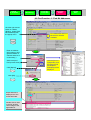
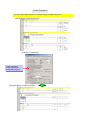
1
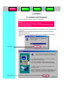
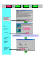
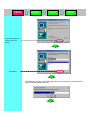
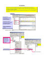
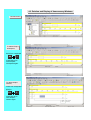
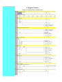
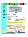
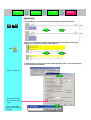
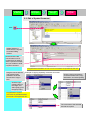
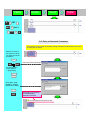
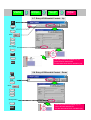
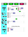
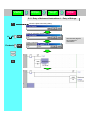
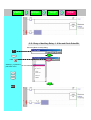
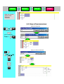
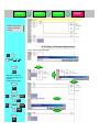
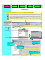
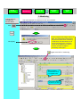
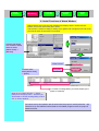
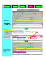
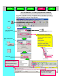
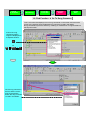
The CD-ROM of CX-Programmer has User's Manual of the PDF file. Please read the 'Notice' and the 'Precautions' in the User's Manual before using CXProgrammer. The 'CX-Programmer Introduction Guide' describes the basic operation procedure of CXProgrammer. Refer to the Help or the User's Manual of the PDF file for detailed descriptions. * You need Acrobat Reader 4.0 or grater versions in your PC to display the PDF file. Contents Available Device Types Available PC Chapter 1 Installation - Startup 1. Installation 1-1. Installation of CX-Programmer • • • • • • • • • • • • • • • • • • • • • • • • • • • • • • • • • • • • • • • • • • • 1-1 1-2. Installation of OMRON FB Library • • • • • • • • • • • • • • • • • • • • • • • • • • •• • • • • • • • • • • • • • 1-4 1-3. Installation of CX-Server • • • • • • • • • • • • • • • • • • • • • • • • • • • • • • • • • • • • • • • • • • • • • • • 1-4 2. Startup of CX-Programmer • • • • • • • • • • • • • • • • • • • • • • • • • • • • • • • • • • • • • • • • • • • • • • • • 1-6 3. New Project Opening and Device Type Settings • • • • • • • • • • • • • • • • • • • • • • • • • • • • • • • • • • 1-7 4. Main Window • • • • • • • • • • • • • • • • • • • • • • • • • • • • • • • • • • • • • • • • • • • • • • • • • • • • • • • • • • 1-8 4-1. Compatible SYSWIN Key Allocation • • • • • • • • • • • • • • • • • • • • • • • • • • • • • • • • • • • • • • • 1-9 4-2. Section • • • • • • • • • • • • • • • • • • • • • • • • • • • • • • • • • • • • • • • • • • • • • • • • • • • • • • • • • • 1-10 4-3. Deletion and Display of Unnecessary Windows • • • • • • • • • • • • • • • • • • • • • • • • • • • • • • 1-12 5. Program Creation • • • • • • • • • • • • • • • • • • • • • • • • • • • • • • • • • • • • • • • • • • • • • • • • • • • • • • 1-13 5-1. Entry of Normally Open Contact • • • • • • • • • • • • • • • • • • • • • • • • • • • • • • • • • • • • • • • • • 1-14 5-2. Entry of Coil • • • • • • • • • • • • • • • • • • • • • • • • • • • • • • • • • • • • • • • • • • • • • • • • • • • • • • • 1-15 5-3. Edit of Symbol Comment • • • • • • • • • • • • • • • • • • • • • • • • • • • • • • • • • • • • • • • • • • • • • 1-17 5-4. Entry of Rung Comment • • • • • • • • • • • • • • • • • • • • • • • • • • • • • • • • • • • • • • • • • • • • • • 1-18 5-5. Entry of Normally Closed Contact • • • • • • • • • • • • • • • • • • • • • • • • • • • • • • • • • • • • • • • • 1-18 5-6. Entry of Attached Comments • • • • • • • • • • • • • • • • • • • • • • • • • • • • • • • • • • • • • • • • • • • 1-19 5-7. Entry of Differential Contact…Up • • • • • • • • • • • • • • • • • • • • • • • • • • • • • • • • • • • • • • • • 1-20 5-8. Entry of Differential Contact…Down • • • • • • • • • • • • • • • • • • • • • • • • • • • • • • • • • • • • • • 1-20 5-9. Entry of Vertical…Up • • • • • • • • • • • • • • • • • • • • • • • • • • • • • • • • • • • • • • • • • • • • • • • • 1-21 5-10. Entry of Vertical…Down • • • • • • • • • • • • • • • • • • • • • • • • • • • • • • • • • • • • • • • • • • • • • 1-21 5-11. Entry of Advanced Instructions 1 - Entry of Strings • • • • • • • • • • • • • • • • • • • • • • • • • • • 1-22 5-12. Entry of Advanced Instructions 1 - Useful Functions • • • • • • • • • • • • • • • • • • • • • • • • • • 1-23 5-13. Entry of Auxiliary Relay - 1.0 Second Clock Pulse Bit • • • • • • • • • • • • • • • • • • • • • • • • • 1-24 5-14. Entry of Advanced Instructions 2 - Entry of Differential • • • • • • • • • • • • • • • • • • • • • • • • 1-25 5-15. Entry of OR Rung • • • • • • • • • • • • • • • • • • • • • • • • • • • • • • • • • • • • • • • • • • • • • • • • • • 1-26 5-16. Entry of Advanced Instructions 3 - Entry by Fun No. • • • • • • • • • • • • • • • • • • • • • • • • • • 1-27 5-17. Entry of Timer Instructions • • • • • • • • • • • • • • • • • • • • • • • • • • • • • • • • • • • • • • • • • • • • 1-28 5-18. Entry of Counter Instructions • • • • • • • • • • • • • • • • • • • • • • • • • • • • • • • • • • • • • • • • • • 1-29 5-19. Edit of Rungs…Copy & Paste • • • • • • • • • • • • • • • • • • • • • • • • • • • • • • • • • • • • • • • • • 1-30 5-20. Entry of END Instruction • • • • • • • • • • • • • • • • • • • • • • • • • • • • • • • • • • • • • • • • • • • • • 1-30 Chapter 2 Online Operation 1. Program Error Check (Compile) • • • • • • • • • • • • • • • • • • • • • • • • • • • • • • • • • • • • • • • • • • • • 2-1 2. Going Online • • • • • • • • • • • • • • • • • • • • • • • • • • • • • • • • • • • • • • • • • • • • • • • • • • • • • • • • • 2-2 3. Monitoring • • • • • • • • • • • • • • • • • • • • • • • • • • • • • • • • • • • • • • • • • • • • • • • • • • • • • • • • • • • 2-3 4. Monitoring - 2 Monitoring Many Locations in Program at Once • • • • • • • • • • • • • • • • • • • • • • • 2-4 5. Monitoring - 3 Monitoring in Hex • • • • • • • • • • • • • • • • • • • • • • • • • • • • • • • • • • • • • • • • • • • 2-4 6. Monitoring - 4 Watch Window • • • • • • • • • • • • • • • • • • • • • • • • • • • • • • • • • • • • • • • • • • • • • 2-5 7. Monitoring - 5 Present Value Change and Binary Monitoring in Watch Window • • • • • • • • • • • 2-6 8. Useful Functions of Watch Window • • • • • • • • • • • • • • • • • • • • • • • • • • • • • • • • • • • • • • • • • • 2-7 9. Monitoring - 6 Watch Window - 2 • • • • • • • • • • • • • • • • • • • • • • • • • • • • • • • • • • • • • • • • • • • 2-8 10. Monitoring - 7 Rung-wrap of Long Rung on Display • • • • • • • • • • • • • • • • • • • • • • • • • • • • • 2-9 11. Monitoring - 8 Differential Monitor • • • • • • • • • • • • • • • • • • • • • • • • • • • • • • • • • • • • • • • • • 2-10 12. Force On/Off • • • • • • • • • • • • • • • • • • • • • • • • • • • • • • • • • • • • • • • • • • • • • • • • • • • • • • • • 2-11 13. Displaying List of Forced-on/off Bits • • • • • • • • • • • • • • • • • • • • • • • • • • • • • • • • • • • • • • • • 2-11 14. Changing Set Value of Timer • • • • • • • • • • • • • • • • • • • • • • • • • • • • • • • • • • • • • • • • • • • • 2-12 15. Changing Present Value of Timer • • • • • • • • • • • • • • • • • • • • • • • • • • • • • • • • • • • • • • • • • 2-12 16. Find Function - 1 Find from Address Reference Tool • • • • • • • • • • • • • • • • • • • • • • • • • • • 2-13 17. Find Function - 2 Retrace Find of Ladders • • • • • • • • • • • • • • • • • • • • • • • • • • • • • • • • • • • 2-14 18. Find Function - 3 Find by Keyword in Comment • • • • • • • • • • • • • • • • • • • • • • • • • • • • • • • 2-16 19. Find Function - 4 Go To Rung Comment • • • • • • • • • • • • • • • • • • • • • • • • • • • • • • • • • • • • 2-17 20. Find Function - 5 Find Bit Addresses • • • • • • • • • • • • • • • • • • • • • • • • • • • • • • • • • • • • • • • 2-18 21. Online Edit • • • • • • • • • • • • • • • • • • • • • • • • • • • • • • • • • • • • • • • • • • • • • • • • • • • • • • • • • 2-19 Useful Functions • • • • • • • • • • • • • • • • • • • • • • • • • • • • • • • • • • • • • • • • • • • • • • • • • • • • Appendix Available Device Types CX-Programmer supports the following PLC (Programmable Logic Controller) types. Series CPU Unit Type CS1 CS1H-CPU67/66/65/64/63 (-V1) CS1G-CPU45/44/43/42 (-V1) CS1G-CPU45H/44H/43H/42H CS1H-CPU67H/66H/65H/64H/63H CS1D-CPU67H/65H CS1D-CPU67S/65S/44S/42S CJ1 CJ1G-CPU45/44 CJ1M-CPU23/22/21/13/12/11 CJ1G- CPU45H/44H/43H/42H CJ1H-CPU66H/65H C1000H C1000H-CPU01 (-V1) C2000H C2000H-CPU01 (-V1) (Simplex system only) C200H C200H-CPU01/02/03/11/21/22/23/31 C200HX C200HG C200HE C200HX-CPU34/44/54/64 C200HG-CPU33/43/53/63 C200HE-CPU11/32/42 C200HX-Z C200HG-Z C200HE-Z C200HX-CPU34-Z/CPU44-Z/CPU54-Z/CPU64-Z/CPU65-Z/CPU85-Z C200HG-CPU33-Z/CPU43-Z/CPU53-Z/CPU63-Z C200HE-CPU11-Z/CPU32-Z/CPU42-Z C200HS C200HS-CPU01/03/21/23/31/33 CPM2* (*1) CPM2A-20CD/30CD/40CD/60CD CPM2C-10CD/10C1D/20CD/20C1D CPM2*-S* (*1) CPM2C-S100C/110C CPM2C-S110C-DRT CPM1/CPM1A (*1) CPM1(A)-10CDR/20CDR/30CDR/40CDR (-V1) CQM1H CQM1H-CPU11/21/51/61 CQM1 CQM1-CPU11/21/41/42/43/44/45 CV1000 (*2) CV1000-CPU01 (-V1) CV2000 (*2) CV2000-CPU01 (-V1) CV500 (*2) CV500-CPU01 (-V1) CVM1 CVM1-CPU01/11 (-V1) (-V2)/CPU21-V2 IDSC IDSC-C1DR-A/C1DT-A SRM1 (*1) SRM1-C01/C02 (-V1) (-V2) SYSMAC Board, or SYSMAC CS1 Board C200PC-ISA01 (C200HG-CPU43 *3) C200PC-ISA02-DRM (C200HG-CPU43 *3) C200PC-ISA02-SRM (C200HG-CPU43 *3) C200PC-ISA03 (C200HG-CPU43 *3) C200PC-ISA03-DRM (C200HG-CPU43 *3) (Internal connection of a PC with the SYSMAC board that is built-in the PC where CXProgrammer is installed) C200PC-ISA03-SRM (C200HG-CPU43 *3) C200PC-ISA13-DRM (C200HX-CPU64 *3) C200PC-ISA13-SRM (C200HX-CPU64 *3) CS1PC-PCI01-DRM (CS1G-CPU45 *4) *1: For WS02-CXPC2-EV5 (one license (limited to micro PLCs)), only these PLC types are available. *2: CX-Programmer does not support SFC. *3: To connect with SYSMAC Board, specify the PLC types in parentheses. Only when selecting these PLC types, you can select “SYSMAC Board” as a network type. *4: To connect with SYSMAC CS1 Board, specify PLC types in parentheses. Only when selecting these PLC types, you can select “CS1 Board” as a network type. Available PC Hardware Requirements OS Windows95/98/NT4.0 Service Pack6 Windows2000/Me Windows XP PC PC/AT Compatible PC/AT Compatible PC/AT Compatible CPU Pentium-class CPU 133MHz or grater Pentium-class CPU 150MHz or grater Pentium-class CPU 300MHz or grater Memory (RAM) In using CX-Simulator together, values in parentheses 48M bytes or grater (64M bytes or grater) 96M bytes or grater (128M bytes or grater) 128M bytes or grater (192M bytes or grater) Hard disk space 100M bytes or more free space 100M bytes or more free space 100M bytes or more free space Display 800X600 SVGA or grater 800X600 SVGA or grater 800X600 SVGA or grater CD-ROM drive At least one drive At least one drive At least one drive Item Communications Port At least one RS-232C Port Recommendation OS Windows95/98/NT4.0 Service Pack6 Windows2000/Me Windows XP PC PC/AT Compatible PC/AT Compatible PC/AT Compatible CPU Pentium-class CPU 450MHz or grater Pentium-class CPU 450MHz or grater Pentium-class CPU 600MHz or grater 128M bytes or grater 192M bytes or grater 256M bytes or grater Hard disk space 150M bytes or more free space 150M bytes or more free space 150M bytes or more free space Display 1024X786XGA or grater 1024X786XGA or grater 1024X786XGA or grater CD-ROM drive Communications Port At least one drive At least one drive At least one drive Item Memory (RAM) At least one RS-232C Port Note that CX-Programmer does not work on Microsoft Windows3.1. The capacity of memory required for operation depends on your program size and OS. If the capacity of your PC is below the memory required for CX-Programmer, the operation of CX-Programmer may become very slow. Required memory size: Calculate the memory required for your program by using the following measuring stick; “memory required for a program of 1k step= 0.5M bytes”, and add it to the memory shown in the above Hardware Requirements table. Ex. Memory size necessary for downloading a program of 250k steps to CX-Simulator and operating it (OS: Windows2000): Memory size necessary for operation = (Memory size shown in the Hardware Requirements table)+ 0.5M bytes x (Program size) = 128M bytes + 0.5M bytes x 250 = 253M bytes In this example, the capacity of memory necessary for operation is at least 256M bytes. Installation Installation to to Startup Startup Opening Opening aa new new project project Device Device type type settings settings Creating Creating aa program program 1. Installation 1-1. Installation of CX-Programmer Follow the below procedure to install CX-Programmer. Caution zClose all Windows programs before installation. zIf an old CX-Programmer is installed, be sure to uninstall the old version before installing Version 5. 1. Insert the installation disk (CD-ROM) of CX-Programmer into the CD-ROM drive of your PC. The setup program automatically starts and the [Choose Setup Language] dialog box is displayed. If this dialog box is not displayed, double-click the CD-ROM drive on Windows Explorer. Click [OK]. 2. Click [OK] if you want to install the English edition. Click [Next]. Installation Installation to to Startup Startup Opening Opening aa new new project project Device Device type type settings settings Creating Creating aa program program The [Software License Agreement] dialog box is displayed. After After checking checking the the contents, contents, click click [Yes] [Yes] ifif you you accept accept all the terms. all the terms. Enter User’s name Company name License No. Click [Next]. Your license number is shown in the provided Software License Agreement / User Registration Form. A confirmation dialog is displayed for your name, company name and license number. Click [Yes] if all are entered correctly. Installation Installation to to Startup Startup Opening Opening aa new new project project Device Device type type settings settings Creating Creating aa program program Check the destination location and click [Next]. Click [Next]. The installation program is executed and the files of CX-Programmer are automatically copied under the specified directory. Installation Installation to to Startup Startup Opening Opening aa new new project project CX-Programmer Ver.5.0 install CD includes the OMRON FB Library setup program. You can choose start setup program for the OMRON FB Library. Device Device type type settings settings Creating Creating aa program program 1-2. Installation of OMRON FB Library OMRON FB Library, or Function Block are available only for CS1/CJ1-H, CJ1M Ver.3.0 or higher CPU. Click [Yes]. Refer Function Block Introduction Guide for the OMRON FB Library and FB (Function Block) in detail. Click [Next]. Click [Next]. Click [Finish]. The installation program is executed and the files of the OMRON FB Library are automatically copied under the specified directory. ‘Setup Complete’ Dialog is shown, then click [Finish] button. 1-3. Installation of CX-Server Click [Yes]. According to your PC environment, a confirmation dialog box may be displayed to prompt you to install Internet Explore Ver.5.5 if Internet Explore Ver.5.0 or greater versions are not installed in your PC. Install it according to the directions on the screen. Installation Installation to to Startup Startup Opening Opening aa new new project project Device Device type type settings settings Creating Creating aa program program Click [Next]. The The [Choose [Choose Destination Destination Location] Location] dialog dialog is is displayed. displayed. Click Click [Next]. [Next]. Click [Next]. The installation program is executed and the files of CX-Server are automatically copied under the specified directory. Click [Finish]. Here is the end of the installation of CX-Programmer and CX-Server. “Readme file” is displayed. Before Before starting starting to to use use CX-Programmer, CX-Programmer, be be sure sure to to read read “Readme “Readme file”. file”. Installation Installation to to Startup Startup Opening Opening aa new new project project Device Device type type settings settings 2. Startup of CX-Programmer Windows task bar [Start] L [Programs] L Omron L [CX-Programmer] L [CX-Programmer] The initial screen when starting up CX-Programmer is displayed. Creating Creating aa program program Installation Installation to to Startup Startup Opening Opening aa new new project project Device Device type type settings settings Creating Creating aa program program 3. New Project Opening and Device Type Settings Click the toolbar button [New] in CX-Programmer. Click Click the left mouse button. Click the left mouse button on the “Settings” button to show the [Device Type Settings] dialog. Click the left mouse button on and select a CPU type. Click [OK] to decide the selected CPU type. 4. Main Window Each function of the main window is explained here. Information Window Title Bar Menus Toolbars Project Tree Symbol Bar Section Status Bar Project Workspace Name Ladder Window Output Window Contents/Function Title Bar Shows the file name of saved data created in CX-Programmer. Menus Enable you to select menu items. Toolbars Enable you to select functions by clicking icons. Select [View] -> [Toolbars], and you can select toolbars to be displayed. Dragging toolbars enables you to change the display positions by the group. Section Enables you to divide one program into a given number of blocks. Each can be created and displayed. Project Workspace Project Tree Controls programs and data. Enables you to copy data by the element by executing Drag and Drop between different projects or within a project. Ladder Window A screen for creating and editing a ladder program. Output Window Shows error information in compiling (error check). Shows the results of searching for contacts/coils in the list form. Shows error details when errors occurred while loading a project file. Status Bar Shows information such as a PLC name, online/offline, location of an active cell. Information Window Displays a small window to show the basic shortcut keys used in CX-Programmer. Select [View] -> [Information Window] to show or hide the Information window. Symbol Bar Displays the name, address or value, and comment of the symbol presently selected by the cursor. 4-1. Compatible SYSWIN Key Allocation The keyboard mapping function allows the function keys to operate like SYSWIN. Select the [Tools] -> [Keyboard Mapping...] menu. Function keys will be available for entering ladder programs. Click Click After the above operations, the key allocations will be changed and become compatible with SYSWIN. Click When When SYSWIN SYSWIN key key allocation allocation is is selected, selected, aa key key operation operation guide guide will will be be displayed displayed at at the the bottom bottom of of the the display. display. Right mouse-click Click the icon shown in the task bar on the rightbottom of the display. Display in Normal View When Shift is pressed When Ctrl is pressed When Alt is pressed Display in Full View 4-2. Section Section is a function to create/display a “block” of a program divided per function. It improves not only the visibility of a program but also the development productivity by reusing components if the program consists of similar controls, because copy and paste on the program tree are available. Moreover, program upload by section is possible and it enables you to do online operation smoothly. Example Giving names indicating the contents of processing or controls is possible. Changing the order of sections and copy & paste are possible by drag & drop with a mouse. There is no limit on the number of sections per program. Changing a section name Click the right button of the mouse on the section whose name is to be changed. Select [Rename]. Enter a given name. Addition of a section Click the right mouse button on [NewProgram1]. Select [Insert Section]. Perform the same operation as the previous page to name the inserted section. It is possible to go to each section (a ladder block) from a section list. As checking the global image (control flow) of a program on the section list, you can go to a specified section. Double-click a section that you want to check its ladder. 4-3. Deletion and Display of Unnecessary Windows Normal screen To delete Project Workspace, Press from a keyboard Alt 1 Press [Alt]+[1] to show Project Workspace again. To delete Output Window, Press from a keyboard [ESC] or Alt 2 Press [Alt]+[2] to show Output Window again. 5. Program Creation Coding of a simple program is explained here. Installation Installation to to Startup Startup Opening Opening aa new new project project Device Device type type settings settings Creating Creating aa program program After checking the cursor position at the upper left of Ladder Window, start programming. 5-1. Entry of Normally Open Contact C 0 Press [C] from a keyboard to open the [New Contact] dialog. 0 of the upper digit of an address can be omitted. ENT Switch 1 ENT Enter a symbol comment. Deletion of instructions z Move the cursor to the instruction and then press the DEL key. z Move the cursor to the right cell of the instruction and press the BS key. 0 of the upper digit of an address is omitted when shown. [.] (period) is displayed between a channel number and a relay number. Installation Installation to to Startup Startup Opening Opening aa new new project project Device Device type type settings settings Creating Creating aa program program 5-2. Entry of Coil O Press [O] from a keyboard to open the [New Coil] dialog. 100 ENT Coil 0 ENT Press [R] to normalize a rung. R Rungs are also normalized when you move the cursor position to the cell inverted in blue by pressing the arrow keys from a keyboard or using a mouse. Useful Useful Function: Function: Automatic Automatic check check of of duplicated duplicated coils coils IfIf aa duplicated coil is entered during program duplicated coil is entered during program creation, creation, the the following following message message is is displayed and you can notice that the coil is duplicated right away. displayed and you can notice that the coil is duplicated right away. Press the [ESC] key to close the open Output Window. Output Window automatically opens. Double-click by using a mouse (or press F4). The cursor moves to the place of the applicable coil on Ladder Window. Double-click Double-click The place of a duplicated coil in the program is displayed. Installation Installation to to Startup Startup Opening Opening aa new new project project Device Device type type settings settings Creating Creating aa program program [Reference] 1. Press [Alt]+[Y]. You can switch showing/hiding of Symbol Comment. Alt Y 2. Click the toolbar button [Show Program/Section Comments] to switch the display of the comments shown in the head row. Click 3. Select [Tools] | [Options] from the CX-Programmer menu. You can set hiding of the comment entry dialog. [Tools] -> [Options] Click the check box to remove the check mark. The comment entry dialog is not displayed anymore. Installation Installation to to Startup Startup Opening Opening aa new new project project Device Device type type settings settings Creating Creating aa program program 5-3. Edit of Symbol Comment Click Ladder Window is switched to the Symbol Comment Editing window. Double-click the left mouse button on a bit number that you want to enter a symbol comment, and you will able to enter a symbol comment. Copy&Paste Copy&Paste and and deletion deletion of of one one or or more more comments comments are are possible possible by by the the cell. cell. Drag the mouse with the right mouse button pressed to invert the source bits of copy in blue. Example of copying & pasting comments of two bits Click the right mouse button on the bit number of the copy destination, and select [Paste]. Click the right mouse button on the range, and select [Copy] from the popup menu. Copy&Paste Copy&Paste of of symbol symbol comments comments is is possible possible between between Excel Excel and and CX-Programmer CX-Programmer too. too. The comments of the selected two bits are copied. Installation Installation to to Startup Startup Opening Opening aa new new project project Device Device type type settings settings Creating Creating aa program program 5-4. Entry of Rung Comment Move the cursor to this position. (The rung is inverted in blue.) ENT The entry screen shows up. [Process_at_Startup] Enter a rung comment. ENT 5-5. Entry of Normally Closed Contact / 1 ENT Sensor 1 ENT Press “/” from a keyboard to show the [New Closed Contact] dialog. Installation Installation to to Startup Startup Opening Opening aa new new project project Device Device type type settings settings Creating Creating aa program program 101 O ENT Coil 1 ENT R 5-6. Entry of Attached Comments This function is very useful for keeping change histories at maintenance and notes of debug bits at startup. Move the cursor to the contact to which you want to write an annotation. Alt ENT The entry screen shows up. Or click the right mouse button. -> [Properties] Enter [Mar. 2002 Added by Tanaka, Maintenance Dept.]. ENT Press [Alt] + [A] to switch showing/hiding of attached comments. Installation Installation to to Startup Startup Opening Opening aa new new project project Device Device type type settings settings Creating Creating aa program program 5-7. Entry of Differential Contact…Up C 100 Click Click [Up]. ENT ENT C This entry method is available only for CS/CJ and CV series PLCs. For the other series PLCs, use DIFU (13). 5-8. Entry of Differential Contact…Down 101 Click Click [Down]. ENT This entry method is available only for CS/CJ and CV series PLCs. For the other series PLCs, use DIFD (14). Installation Installation to to Startup Startup Opening Opening aa new new project project Device Device type type settings settings 5-9. Entry of Vertical…Up ↑ Ctrl Or U 200 O ENT Coil 2 ENT R 200 C ENT ENT 300 O ENT Coil 3 ENT 5-10. Entry of Vertical…Down ← ↓ Ctrl Or V Creating Creating aa program program Installation Installation to to Startup Startup Opening Opening aa new new project project Device Device type type settings settings Creating Creating aa program program 5-11. Entry of Advanced Instructions 1 - Entry of Strings I Show the [New Instruction] dialog. Enter an instruction and its operand. ++ d0 ENT Enter a comment. Products R ENT See the next page for the contents of instructions. Installation Installation to to Startup Startup Opening Opening aa new new project project Device Device type type settings settings Creating Creating aa program program 5-12. Entry of Advanced Instructions 1 - Useful Functions Click Instruction Help Function Click The reference guide screen of the . instruction shows up. Find Instruction Function Click . The list of advanced instructions per function shows up. PLCs supporting the applicable instruction are listed. Installation Installation to to Startup Startup Opening Opening aa new new project project Device Device type type settings settings Creating Creating aa program program 5-13. Entry of Auxiliary Relay - 1.0 Second Clock Pulse Bit Show the [New Contact] dialog. C Click Select [P_1s] from the pull-down menu. ENT Installation Installation to to Startup Startup Opening Opening aa new new project project Device Device type type settings settings Creating Creating aa program program Refer to the former pages to execute coding. 5-14. Entry of Advanced Instructions 2 - Entry of Differential Instructions Differential Instructions…Instructions executed in only one scan when running a program. Show the [New Instruction] dialog. I Enter @MOV #0 D100 Attach Attach @ @ (at (at mark) mark) before instructions. before instructions. ItIt makes makes the the instructions instructions differential. differential. ENT ENT R Enter a comment if necessary. Installation Installation to to Startup Startup Opening Opening aa new new project project Device Device type type settings settings Creating Creating aa program program Refer to the former pages to execute coding. 5-15. Entry of OR Rung ENT 3 W ENT ENT Entry of comments is omitted here. ENT W 4 ENT ENT ↑ ↑ Refer Refer to to the the section section 5566 to enter annotations. to enter annotations. Installation Installation to to Startup Startup Opening Opening aa new new project project Device Device type type settings settings Creating Creating aa program program 5-16. Entry of Advanced Instructions 3 - Entry by Fun No. Show Show the the [New [New Instruction] Instruction] dialog. dialog. I 021 The The instruction instruction corresponding corresponding to to the the entered entered Fun Fun No. No. is is displayed. displayed. Enter ENT #0 D0 ENT Refer to the section 5-4 to enter a rung comment. R Note: Note: The The Fun Fun No. No. of of MOV MOV depends depends on on PLC PLC types. types. CS-series CS-series -> -> 021 021 CJ-series CJ-series -> -> 021 021 CV-series CV-series -> -> 030 030 C-series C-series -> -> 21 21 Installation Installation to to Startup Startup Opening Opening aa new new project project Device Device type type settings settings Refer Refer to to the the former former pages pages to to enter enter rungs rungs and and comments. comments. 5-17. Entry of Timer Instructions Entry of a Timer bit T0 / ENT *T0: Indicates TIM0. Enter a comment. Timer 1 ENT Entry of a Timer instruction I TIM 0 #30 ENT R Creating Creating aa program program Installation Installation to to Startup Startup Opening Opening aa new new project project Device Device type type settings settings Creating Creating aa program program Refer Refer to to the the former former pages to pages to execute execute coding. coding. 5-18. Entry of Counter Instructions Entry of a Counter instruction I CNT 0 #5 ENT Move the cursor by using arrow keys or a mouse. Enter a bit for reset. R C C0 ENT ENT O 402 ENT ENT R Entry of a Counter bit Installation Installation to to Startup Startup Move Move the the cursor cursor to to this this position. position. The The rung rung is is inverted inverted as as shown shown right. right. Ctrl Opening Opening aa new new project project Device Device type type settings settings Creating Creating aa program program 5-19. Edit of Rungs …Copy & Paste Refer to the former sections to enter a rung. C (Copy a rung) You can copy instructions selected by dragging a mouse. You can also cut selected rungs (instructions) by [Ctrl]+[X]. ↓ Press Press the the ↓↓ key key to to move the cursor move the cursor to to this this position. position. Ctrl V (Paste a copied rung) Click Click each each instruction instruction and then and then change change the the bit bit numbers. numbers. When making a mistake, press press or [Ctrl+Z] for Undo (return to the previous operation) or [Ctrl+Y] for Redo (go to the next operation) 5-20. Entry of END Instruction At At the the creation creation of of aa new new project, project, aa section of the END instruction section of the END instruction only only is is automatically generated. automatically generated. You You do do not not need need to to enter enter an an END END instruction. instruction. Note: The END section is not generated when you load a program created with CX-Programmer V2 or the former versions. Online Online to to Transfer Transfer Monitoring Monitoring Force Force On On Force Force Off Off Program Program Check Check 1. Program Error Check (Compile) Before program transfer, check errors. Click Errors Errors and and addresses addresses are displayed are displayed on on Output Output Window. Window. Double-click Double-click aa displayed displayed error, error, and and the cursor the cursor in in Ladder Ladder Diagram Diagram will will go go to to the the corresponding error corresponding error location location and and the the error error rung will be shown rung will be shown in in red. red. Modify Modify the the error. error. Output Window automatically opens at program check. The cursor moves to an error location by pressing J or F4 key. z Output Window closes by pressing the ESC key. z z Online Online Edit Edit Online Online to to Transfer Transfer Monitoring Monitoring Force Force On On Force Force Off Off Program Program Check Check Online Online Edit Edit 2. Going Online CX-Programmer provides three kinds of connecting methods depending on usage. Normal Normal online. online. Enables Enables you you to to go go online online with with aa PLC PLC of of the the device device type type and and method method specified specified when when opening opening aa project. project. Auto Auto online. online. Automatically Automaticallyrecognizes recognizes the the connected connected PLC PLC and and enables enables you you to to go go online online with with aa PLC PLC with with one one button. button. -> -> Uploads Uploads all all data data such such as as programs programs from from the the PLC. PLC. Online Online with with Simulator. Simulator. Enables Enables you you to to go go online online with with CX-Simulator CX-Simulator with with one one button button (You (You need need to to install install CX-Simulator.) CX-Simulator.) This This time, time, online/debug online/debug functions functions when when working working online online with with CX-Simulator CX-Simulator are are explained explained in in this this guide (Install CXguide (Install CXSimulator Simulator separately). separately). Click Click [OK]. Program transfer starts. Click [OK]. The The background background color color of of Ladder Ladder Window Window changes changes to to gray. gray. The The CX-Simulator CX-Simulator Console Console box box is is shown. shown. The The operating operating mode mode of of the the active active PLC PLC is is shown. shown. Scan Scan time time is is displayed displayed (except (except for for Program Program Mode). Mode). Online Online to to Transfer Transfer Monitoring Monitoring Force Force On On Force Force Off Off Program Program Check Check Online Online Edit Edit 3. Monitoring Change Change the the PLC PLC (simulator) (simulator) to to Monitor Monitor Mode. Mode. The on/off statuses of contacts and coils are monitored. Click Click [Yes]. If your program has a large volume of data, the scroll speed of the screen may become slow when monitoring. In that case, click the below icon to cancel monitoring once, scroll the screen to the address you want to monitor, and then change to monitoring mode again. toggles on/off of PLC monitoring. The The rungs rungs being being monitored monitored are are shown shown in in aa specified specified color. color. The The present present value value of of I/O I/O memory memory is is shown. shown. Online Online to to Transfer Transfer Monitoring Monitoring Force Force On On Force Force Off Off Program Program Check Check Online Online Edit Edit 4. Monitoring - 2 Monitoring Many Locations in Program at Once Move Move the the mouse mouse pointer pointer to to the the arrow arrow position shown position shown in in the the right figure and drag right figure and drag the the cursor cursor down down with with the left mouse the left mouse button button pressed. pressed. You can split Ladder Window and monitor more than one location in a program at once. The The screen screen is is divided divided into into two two panes panes up up and and down, down, and and you you can can display display any any address address in in two two panes panes respectively respectively by by using using the the scroll scroll bars. bars. 5. Monitoring - 3 Monitoring in Hex Click Shown in decimal Shown in hex to switch the display format of the present value of IO memory between decimal and hexadecimal. Online Online to to Transfer Transfer Monitoring Monitoring Force Force On On Force Force Off Off Program Program Check Check Online Online Edit Edit 6. Monitoring - 4 Watch Window I/O monitoring of the addresses specified in Watch Window is executed. Display Watch Window. Alt 3 Enter a bit number that you want to monitor. 400 ENT Press the ENT key continuously for auto increment of addresses. You You can can also also enter enter aa given given address address in in this this status. status. ENT ENT ENT Entry Entry of of BOOL BOOL type type (contact) (contact) The addresses registered in Watch Window are still stored when CX-Programmer is opened next time. Example: Entry of 4CH 00Bit Enter Enter “.” “.” (period) (period) between between CH CH and and Bit. Bit. Or Or enter enter “400” “400” without without aa period period in in the the “Name “Name or or address” address” box box and and then then specify specify “BOOL” “BOOL” in in the the “Data “Data Type/Format” Type/Format” box box (Reverse (Reverse the the box box and and then then press press BB key key form form the the keyboard.) keyboard.) Online Online to to Transfer Transfer Monitoring Monitoring Force Force On On Force Force Off Off Program Program Check Check Online Online Edit Edit 7. Monitoring - 5 Present Value Change and Binary Monitoring in Watch Window The present values of bits and words are changed in Watch Window. In Watch Window, binary monitoring is possible for the data that can be treated by the word. Double-click the mouse. An entry dialog opens. Click Enter a new value that you want to change to. 4-word 4-word data data is is displayed displayed in in the the binary binary system. system. As shown in the guidance at the bottom of the dialog, Force On/Off and Set On/Off are enabled also by key operation. Click the right mouse button on a bit, and you will be able to select Force On/Off and Set On/Off from the popup menu. Online Online to to Transfer Transfer Force Force On On Force Force Off Off Monitoring Monitoring Program Program Check Check Online Online Edit Edit 8. Useful Functions of Watch Window Watch Window has a function that classifies and displays data in sheets like MSEXCEL and names each sheet given names. This function is useful for debug or startup if you gather and manage the bits and words you want to check as one block in one sheet. Click Click the the right right button button of of aa mouse mouse on on Sheet1, Sheet1, and and then then select select [Watch [Watch Sheet] Sheet] -> -> [Rename]. [Rename]. Enter Enter aa name. name. To To add add aa sheet, sheet, select select [Watch [Watch sheet] sheet] -> -> [Insert]. [Insert]. Click Click [OK]. [OK]. It is useful to manage data if you name sheets by the phase or assembly. Right-click Right-click on on Watch Watch Window. Window. -> -> Select Select [View] [View] from from the the popup popup menu. menu. And And then then you you will will be be able able to to choose choose showing/hiding showing/hiding of of each each item item on on Watch Watch Window. Window. The The names names set set by by this this operation operation are are all all saved saved when when the the project project is is saved saved (extension: (extension: .opt). .opt). Therefore, Therefore, they they are are loaded loaded as as well well as as data data such such as as ladder ladder programs programs when when the the project project is is loaded loaded next next time. time. Online Online to to Transfer Transfer Monitoring Monitoring Force Force On On Force Force Off Off Program Program Check Check Online Online Edit Edit 9. Monitoring - 6 Watch Window - 2 Move Move the the mouse mouse cursor cursor to to this this position. position. Drag & Drop from Ladder Diagram enables you to add an address to be monitored. Drag Drag and and drop drop on on Watch Watch Window. Window. Data Data such such as as rungs, rungs, bits bits per per block, block, or or operands operands of of advanced advanced instructions instructions is is pasted on Watch Window. pasted on Watch Window. Moreover, Moreover, the the on/off on/off statuses statuses of of the the bits bits and and the the present present values values of of words words are displayed. are displayed. Online Online to to Transfer Transfer Monitoring Monitoring Force Force On On Force Force Off Off Program Program Check Check Online Online Edit Edit 10. Monitoring - 7 Rung-wrap of Long Rung on Display This function makes a rung longer than the right bus bar as shown in the below figure wrap when displayed. Select [View] -> [Show in RungWrap]. The rung is wrapped at the right bus bar. Once set, this function is always active until released by taking the reverse procedure of the above one. Online Online to to Transfer Transfer Monitoring Monitoring Force Force On On Force Force Off Off Program Program Check Check Online Online Edit Edit 11. Monitoring - 8 Differential Monitor The function detects differential up/down of a specified bit and indicates that differential conditions are satisfied by sound or display. The function eliminates the use of a trap rung for checking operation and improves the efficiency of programming and debug operations. Move the cursor to a bit to be monitored. Click Or click the right mouse button on the applicable bit and select [Differential Monitor] from the popup menu. Click [Start]. The The count count number number is is displayed displayed on on the the dialog every time the differential dialog every time the differential condition condition (differential (differential up up in in this this example) is satisfied and example) is satisfied and the the color color of of the box changes each time. the box changes each time. Online Online to to Transfer Transfer Monitoring Monitoring Force Force On On Force Force Off Off Program Program Check Check Online Online Edit Edit 12. Force On/Off Move the cursor to a contact or coil that you want to force on/off. Click Click the the right right mouse mouse button. button. -> -> [Force] [Force] -> -> [On] [On] Force Force Off/Cancel Off/Cancel of of bits/coils bits/coils are are enabled enabled in in the the same same way. way. Shortcut Shortcut Key Key Ctrl+J: Ctrl+J: Force Force On On Ctrl+K: Ctrl+K: Force Force Off Off Display Project Workspace. [Alt] + 1 Double-click [Memory]. Click the [Address] tab. Double-click [Forced Status]. Contacts/coils are forced on/off from CX-Programmer. mark indicates that the bit is now being forced on/off. Once bits/coils are forced on/off, the forced statuses are held until cancelled or the reverse procedures of on/off are taken. The statuses do not change by an external input or the operational result of the program. Moreover, force operations are not enabled when the PLC is in the Run mode. 13. Displaying List of Forced-on/off Bits The bits forced on/off can be listed in a table. This function enables you to check the forced statuses of more than one bit at a glance. Online Online to to Transfer Transfer Monitoring Monitoring Force Force On On Force Force Off Off Program Program Check Check Online Online Edit Edit 14. Changing Set Value of Timer The set value of a timer is changed while CPU is running (in the Monitor mode only). Move the cursor to the set value of a timer. Enter the new set value #100. ENT Or double-click. Click [OK] to complete. 15. Changing Present Value of Timer The present value of a timer is changed while CPU is running (in the Monitor mode only). Move the cursor to the present value of a timer. Enter a new present value 5000. ENT Or double-click. Click [Set] to complete. Subtraction starts from the new value 5000. Online Online to to Transfer Transfer Monitoring Monitoring Force Force On On Force Force Off Off Program Program Check Check Online Online Edit Edit 16. Find Function - 1 Find from Address Reference Tool Display Address Reference Tool. Alt 4 Reference You You can can also also move move the the cursor cursor to to aa bit bit that that you you want want to to find. find. Click a bit that you want to find, and the focus will move to the corresponding position in the rung. 1 Enter Enter aa bit bit number number that that you you want want to to find find in in the the [Address] [Address] field. field. 2 Click 3 The The found found bits bits are are listed. listed. Online Online to to Transfer Transfer Monitoring Monitoring Force Force On On Force Force Off Off Program Program Check Check Online Online Edit Edit 17. Find Function - 2 Retrace Find of Ladders The function retraces ladder rungs so that you can find the causes of the coils not turned on. (1)The reason why the coil 3.00 is not turned on is that its contact 2.00 is not turned on. Therefore, the function retraces rungs to find the coil 2.00. (2)Move the cursor to the following position (contact 2.00) and press the [Space] key. Space (3)The reason why the coil 2.00 is not turned on is that the contact 1.00 or 1.01 is not turned on. Suppose the cause is the contact 1.00 and find the coil of 1.00. Move the cursor to the contact 1.00 and press the [Space] key as well as the above operation (2). Space (4)If this rung is not a cause press [Shift]+[Space], and you will able to go back to the rung before you started to find this rung. Shift Space Online Online to to Transfer Transfer Monitoring Monitoring Force Force On On Force Force Off Off Program Program Check Check Online Online Edit Edit (5)Then retrace rungs to find a cause from the contact 1.01. As well as the operations so far, move the cursor to the contact 1.01 and press the [Space] key. Space (6)The focus moves to the coil 1.01. As it turned out, the cause was the contact 0.01 that was not turned on. Press the [Space] key to jump from a coil to a contact having the same address as the coil or from a contact to a coil in reverse. Press the [N] key for another jump from a contact or coil at the cursor position to a next one having the same address. To move back to the position of the last jump, press the [B] key. This is a useful function available in SYSMAC Support Software. CX-Programmer inherits it. Online Online to to Transfer Transfer Monitoring Monitoring Force Force On On Force Force Off Off Program Program Check Check Online Online Edit Edit 18. Find Function - 3 Find by Keyword in Comment If you enter an operator’s name or an operation date in annotations as a note at startup or maintenance, this function finds the bit or word that the name or date is used and displays the result on Output Window. Click The [Find] dialog shows up. Click . Select [All (strings)] from the pull-down menu. Scope of Find is specifiable. Enter a keyword to find. Click PLC To find a target from all tasks (programs). Current view To find from a section or task (program) being edited -> Click an icon in Project Workspace to select a task. Click [OK]. The The contacts/coils contacts/coils of of which which annotations annotations include include the the keyword keyword entered entered in in the the Find Find dialog dialog are are displayed displayed on on Output Output Window. Window. Double-click Double-click an an item, item, and and then then the cursor moves to the the cursor moves to the applicable applicable bit bit in in Ladder Ladder Window. Window. Online Online to to Transfer Transfer Monitoring Monitoring Force Force On On Force Force Off Off Program Program Check Check Online Online Edit Edit 19. Find Function - 4 Go To Rung Comment This is a function that displays a list of rung comments on the screen and moves the cursor to the position where a selected rung comment is used in the ladder. Rung comments improve the efficiency of debug or maintenance of rungs divided into blocks per function. A list of the rung comments used in rungs are displayed on a separate window. L Or Alt Shift R Click a rung comment in the list, and the cursor goes to the position where the rung comment is used in the ladder. Online Online to to Transfer Transfer Monitoring Monitoring Force Force On On Force Force Off Off Program Program Check Check 20. Find Function - 5 Find Bit Addresses Click the right mouse button on Ladder Window. Select [Find Bit Addresses] from the popup menu. Find Addresses and Find Mnemonics are also available. Enter an address (bit number) to find. (period between a channel and a bit is unnecessary.) Set the scope of Find (Current view). Click [Report]. Click [OK]. Output Output Window Window is is displayed displayed and and the the results results are are listed. listed. Double-click Double-click an an item item in in the the list, list, and and the the cursor cursor will will go go to to the the applicable applicable bit. bit. Click the [How to Input] button, and the Help of [Find and Replace Examples] will be displayed. Online Online Edit Edit Online Online to to Transfer Transfer Monitoring Monitoring Force Force On On Force Force Off Off Program Program Check Check Online Online Edit Edit 21. Online Edit (1) Move the cursor to a rung you want to modify. You can also select more than one rung by Drag&Drop with a mouse. (2) Select [Program] -> [Online Edit] -> [Begin] from the CX-Programmer menu. Double-click Double-click (3) Enter a bit number (4.11 in this example) you want to edit to. (4) Select [Program] -> [Online Edit] -> [Send Changes] from the menu. End Useful Functions You can select either vertical or horizontal display of output instructions. Vertical display of output instructions [Tools(T)] -> [Options(O)] Check Check the the [Show [Show output instructions output instructions horizontally horizontally (H)] (H)] box. box. Horizontal display of output instructions