1
MultiModemISI Hybrid Series
Model ISIHI-2S/2U
88301151
Copyright © 1998 by Multi-Tech Systems, Inc.
MultiModemISI Hybrid Series
Model ISIHI-2S/2U
88301151, Revision B
All rights reserved. This publication may not be reproduced, in whole or in part, without prior expressed
written permission from Multi-Tech Systems, Inc.
Copyright © 1998 by Multi-Tech Systems, Inc.
Multi-Tech Systems, Inc. makes no representation or warranties with respect to the contents hereof and
specifically disclaims any implied warranties of merchantability or fitness for any particular purpose.
Furthermore, Multi-Tech Systems, Inc. reserves the right to revise this publication and to make changes
from time to time in the content hereof without obligation of Multi-Tech Systems, Inc., to notify any
person or organization of such revisions or changes.
Record of Revisions
Revision
Date
Description
A
8/11/98
Manual released.
B
12/10/98
Manual revised to include 2U model and minor editorial and formatting
changes.
Patents
This product is covered by one or more of the following U.S. Patent numbers: 5.301.274, 5.309.562,
5.355.365, 5.355.653, 5.452.289, 5.453.986. Other patents pending.
Trademarks
Multi-Tech is a registered trademark of Multi-Tech Systems, Inc.
NetWare is a registered trademark of Novell, Inc.
Pentium is a registered trademark of Intel Corporation.
SCO is a registered trademark of Santa Cruz Operation, Inc.
UNIX is a reigstered trademark of X/Open Company, Ltd.
Windows 95 and Windows NT are registered trademarks of Microsoft.
Multi-Tech Systems, Inc.
2205 Woodale Drive
Mounds View, Minnesota 55112
(612) 785-3500 or (800) 328-9717
U.S. Fax (612) 785-9874
Technical Support (800) 972-2439
BBS (612) 785-3702 or (800) 392-2432
Fax Back (612) 717-5888
Internet Address:http://www.multitech.com
Contents
Introduction
Welcome to Multi-Techs new MultiModem Hybrid Series, model ISIHI-2S/2U, ........................................... 6
Modem Description/Features ............................................................................................................................ 8
Terminal Adapter Description/Features ............................................................................................................. 9
Manual Organization ....................................................................................................................................... 10
Technical Specifications .................................................................................................................................. 12
Physical / Electrical / Environmental ......................................................................................................... 12
Hardware Installation
Introduction ..................................................................................................................................................... 16
Computer Requirements ............................................................................................................................. 16
Shipping Contents ....................................................................................................................................... 16
Safety Warnings .......................................................................................................................................... 16
Before You Start .............................................................................................................................................. 17
Determine Current System Settings ............................................................................................................ 17
Recommended Base I/O Address and IRQ Values ..................................................................................... 17
Installing the ISIHI-2S/2U ............................................................................................................................... 18
LED Indicators ................................................................................................................................................ 20
Software/Driver Installation
Introduction ..................................................................................................................................................... 24
Installing ISIHI-2S/2U Drivers in Windows NT ............................................................................................. 25
Installing Terminal Adapters and Modems to COM Ports in Windows NT ............................................... 27
Removing the Driver .................................................................................................................................. 32
Installing ISIHI-2S/2U Drivers in Windows 95 .............................................................................................. 33
Installing Terminal Adapters and Modems to COM Ports in Windows 95 ................................................ 41
Removing the Driver .................................................................................................................................. 46
Configuring the Terminal Adapter ................................................................................................................... 47
Introduction................................................................................................................................................. 47
North American Users .......................................................................................................................... 47
International Users ............................................................................................................................... 47
Optional Settings .................................................................................................................................. 48
ISDN TA Configuration Utility .................................................................................................................. 49
ConfigMenu Configuration Utility ............................................................................................................. 53
AT Commands ............................................................................................................................................ 54
NetWare Connect (Novell) Driver Installation ................................................................................................ 55
Configuring Ports for NetWare Connect .................................................................................................... 56
Removing the Driver (Novell) .................................................................................................................... 56
SCO Open Server 5 Driver Installation ........................................................................................................... 57
The Multi-Tech Installation Script ............................................................................................................. 58
Activating Ports in SCO Open Server 5 ..................................................................................................... 60
Removing the Driver (SCO Open Server 5) ............................................................................................... 60
Multi_Setup Utility ..................................................................................................................................... 61
Administration Utility ................................................................................................................................. 64
Linux Driver Installation ................................................................................................................................. 65
Miscellaneous: ............................................................................................................................................ 66
MODEM AT Commands, S-Registers, and Result Codes
Modem AT Commands .................................................................................................................................... 68
Modem S-Registers ......................................................................................................................................... 83
Modem Result Codes ....................................................................................................................................... 89
TERMINAL ADAPTER AT Commands, S-Registers, and Result Codes
Terminal Adapter AT Commands .................................................................................................................... 92
Terminal Adapter S-Registers ........................................................................................................................ 105
Terminal Adapter Result Codes ..................................................................................................................... 108
Troubleshooting
Troubleshooting Guide .................................................................................................................................. 112
Service, Warranty, and Technical Support/BBS
Introduction ................................................................................................................................................... 118
Limited Warranty ........................................................................................................................................... 118
Online Warranty Registration ................................................................................................................... 118
Techical Support ....................................................................................................................................... 119
Service ........................................................................................................................................................... 120
The Multi-Tech BBS ..................................................................................................................................... 121
Upgrading the ISIHI-2S/2U with FlashPro ................................................................................................... 123
About CompuServe ....................................................................................................................................... 123
About the Internet .......................................................................................................................................... 123
About the Multi-Tech Fax-Back Service ....................................................................................................... 124
Appendix
Appendix A: Determining Current System Settings ...................................................................................... 126
Appendix B: Base I/O Switch Settings.......................................................................................................... 127
Appendix C: Pin Assignments ....................................................................................................................... 129
Appendix D: ISIHI-2S/2U Testing Utilities .................................................................................................. 130
Appendix E: Configuration Profiles ............................................................................................................. 133
Appendix F: Ordering ISDN BRI (2B+D) Lines .......................................................................................... 137
Appendix G: ASCII Conversion Chart .......................................................................................................... 149
Appendix H: Dial Pulses and Tones .............................................................................................................. 150
Appendix I: AT Command Summary (Modem) ............................................................................................ 152
Appendix J: S-Register Summary (Modem) ................................................................................................. 158
Appendix K: Result Code Summary (Modem) ............................................................................................. 160
Appendix L: AT Command Summary (TA)................................................................................................... 162
Appendix M: S-Register Summary (TA) ....................................................................................................... 168
Appendix N: Result Codes (TA) ................................................................................................................... 169
Appendix O: Regulatory Agency Information .............................................................................................. 170
Glossary
....................................................................................................................................................................... 173
Index
....................................................................................................................................................................... 186
Introduction
MultiModemISI Hybrid Series, ISIHI-2S/2U
1
5
Chapter 1—Introduction
W
elcome to Multi-Tech’s new MultiModem Hybrid Series, model ISIHI-2S/2U,
a multiport hybrid ISDN card for Remote Access Server (RAS) applications. Included on
the ISIHI-2S/2U are four V.90/K56flex central site modems for incoming analog modem
and fax calls, as well as two terminal adapters. Each terminal adapter appears as two ports
to the server PC using the ISIHI-2S/2U. The terminal adapters identify incoming analog
calls and route them to the central site modems. The card also supports dial-out
applications via the modems or terminal adapters.
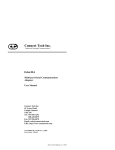
The ISIHI-2S/2U card features eight RAS ports using two Basic Rate Interface (BRI)
ISDN lines. The eight ports allow a server to accept any combination of analog modem
and digital ISDN calls, giving the user the flexibility to customize the settings of the
terminal adapters and modems. Since the two BRI lines constitute only four Bearer
channels, only four of the eight ports can be active at any one time. The two terminal
adapters handle the four B-channels as four independent data connections (see diagram
below).
Com Ports
5
ISDN
Modem
1
2
TA
6
Modem
7
Modem
3456
RJ-45 jack
Line 1
6
TA
8
Modem
3456
RJ-45 jack
3
4
Line 2
MultiModemISI Hybrid Series, ISIHI-2S/2U
Chapter 1—Introduction
From the perspective of the server PC, the ISIHI-2S/2U is an 8-port serial card with eight
devices permanently attached to the serial ports. The first four ports are the two terminal
adapters, each of which appear as two ports. The remaining four ports are the four central
site modems. The chart below summarizes the correlation of ports and devices.
Port Number
1
2
3
4
5
6
7
8
Device
TA
TA
TA
TA
Modem
Modem
Modem
Modem
ISDN Line Number
1
1
2
2
1
1
2
2
The ISIHI-2S/2U server card is ideal for use in PC network environments because it
provides an integrated hardware solution for remote access for both Windows NT and
Novell-based LANs. To ensure smooth Novell network integration, the ISIHI-2S/2U
ships with a NetWare Loadable Module for NetWare Connect communication server
that enables it to support state-of-the-art features such as remote dialing and modem
pooling. The ISIHI-2S/2U easily integrates into the Windows NT platform since it fully
supports Microsofts Remote Access Server software, which allows it to operate
comfortably with popular network protocols such as TCP/IP and Net BIOS.
The ISIHI-2S/2U ships with drivers for other multiuser operating systems such as
SCO®UNIX®.
This Owners Manual will help you install, configure, test, and use the ISIHI-2S/2U. The
manual contains product specifications, installation instructions, and technical support
information to assist you in the installation process. This manual is written for audiences
with basic PC skills; therefore, step-by-step instructions for basic operations such as
logging in and file editing are not included.
MultiModem ISI Hybrid Series, ISIHI-2S/2U
7
Chapter 1—Introduction
Modem Description/Features
ISIHI-2S/2U modems include an Intel 20 MHz 80186 processor and 254K of RAM that
work dynamically to allocate resources to the most active modems.
Simple to install, the ISIHI-2S/2U can be used to add multiport, Enhanced V.34 modem
communications to a network host or server as easily as plugging in an expansion card,
loading the driver software, and connecting the phone lines.
The ISIHI-2S/2U contains four modems, which meet the proposed Enhanced V.34 ITU
standard for data signalling rates as high as 33.6/31.2 Kbps full-duplex mode. They
support and are compatible with EIA extended Automode, adaptive line probing,
automatic symbol rate and carrier frequency during startup, and retrain and rate
renegotiation (in 2400 bps increments.)
The ISIHI-2S/2U features CCITT V.42 error correction and V.42bis data compression,
providing 100% error-free data transmission. V.42 error correction incorporates MNP
Classes 3 and 4 and LAP-M. You can select V.42bis data compression for 4-1 throughput
or MNP Class 5 for 2-1 throughput.
ISIHI-2S/2U modems offer interactive automatic dialing as well as Command Mode
option configuration. You can store up to ten command line/telephone numbers (up to 60
characters each) in the ISIHI-2S/2Us nonvolatile memory.
ISIHI-2S/2U modems offer pulse or tone dialing and recognize dial tones and busy
signals for reliable call-progress detection. They detect AT&T calling card tones and are
FCC-registered for connecting to telephone networks without Data Access Arrangements
(DAAs).
They also feature Remote Configuration, which allows you to assist users at remote sites,
saving you the time and trouble of site visits and preventing misinterpretation of
configuration instructions.
The ISIHI-2S/2U meets the CCITT V.17 standard for sending and receiving faxes. When
lined to a compatible fax machine or modem, ISIHI-2S/2U modems can transmit faxes at
14.4 Kbps. They meet the CCITTs Group 3 Designation for sending and receiving faxes
at 9600 bps and Group 2 Designation for sending and receiving faxes at 1800 bps. The
ISIHI-2S/2U also is downward-compatible to speeds as low as 300 bps, so you can send
and receive faxes with virtually any fax machine in the world.
8
MultiModemISI Hybrid Series, ISIHI-2S/2U
Chapter 1—Introduction
Terminal Adapter Description/Features
ISIHI-2S/2U terminal adapters have S/T ports to connect to the ISDN network and analog
ports to connect to a telephone, modem, or fax machine. They ship with a software
configuration utility for Windows® 95, Windows NT, and ConfigMenu (a built-in
configuration utility for DOS and Windows 3.x operating systems). The TAs also accept
AT commands, enabling them to use the same communications software as analog
modems.
ISIHI-2S/2U terminal adapters are compatible with EuroISDN switch protocol. They
communicate using ISDN BRI (2B+D) service, which provides up to 128 Kbps data and
voice communications. They automatically detect whether an incoming call is voice or
data and handle it appropriately.
The ISIHI-2S/2U terminal adapters communicate over public ISDN telephone lines.
Features include the following:
Compatibility with NET3, AT&T 5ESS, NT DMS-100, US National ISDN-1switch
protocols
Automatically detect if incoming call is voice or data
ISDN BRI (2B+D)
AT command and S-Register controls and Result Code responses
Use the same communications software as existing analog modems
V.120, or PPP compatible
Supports PPP (Point-to-Point Protocol) high speed ISDN connections
Windows NT and Windows 95 software utility and a firmware utility for easy ISDN line
configuration
Flash PROM for easy firmware upgrades
Automatic detection of the data protocol for answering incoming data calls
Embedded protocol analyzer for troubleshooting the connection to the ISDN network
The ISDN TAs provide data communication using Basic Rate Interface (BRI). They
provide two 64 Kbps bearer channels for voice or data and one 16 Kbps D channel for
signaling information (2B+D) and are compatible with V.120 and PPP.
The TAs provides dial-up asynchronous communication capability with other personal
computers, terminals, online computer services, or other types of computer systems.
What is a S/T-Interface? An ISDN Basic Rate (BRI) U-Loop consists of 2 conductors
from the CO (telephone company central office) to the customer premises. Equipment on
both sides of the U-loop is carefully designed to deal with the long length of the U-loop
and the noisy environment it operates in. At the customer premises, the U-loop is
terminated by an NT1 (network termination 1) device. An NT1 (network terminator 1) is
a device that provides an interface between the two-wire twisted-pairs used by telephone
companies in their ISDN BRI network and an end-users four wire terminal equipment.
The NT1 drives an S/T-bus that usually is 4 wires but in some cases may be 6 or 8 wires.
MultiModem ISI Hybrid Series, ISIHI-2S/2U
9
Chapter 1—Introduction
The name of the S/T bus comes from the letters used in the ISDN specifications to refer
to two reference points, S and T. Point T refers to the connection between the NT1
device and customer supplied equipment. Terminals can connect directly to NT1 at point
T, or there may be a PBX (private branch exchange, e.g., a customer-owned telephone
exchange). When a PBX is present, point S refers to the connection between the PBX and
the terminal.
Point S
48 wires
Terminal
NT2
(PBX)
Point S
Terminal
Point T
48 wires
Point U
48 wires
NT2
Telco Company
Interface
Note that in ISDN terminology, terminal can mean any sort of end-user ISDN device,
such as data terminals, telephones, FAX machines, etc. The following diagram reflects
interface points in a typical ISDN network.
Point S
Terminal
Manual Organization
Chapter 1: IntroductionIntroduces and describes the ISIHI-2S/2U. It describes
features, provides manual organization, and lists technical specifications.
Chapter 2: Hardware InstallationDescribes how to install the ISIHI-2S/2U card into
the ISA bus of your personal computer system and how to configure card settings (I/O
address DIP switch setting and jumper setting). This chapter also provides you with
procedures for physically connecting the ISIHI-2S/2U to the ISDN BRI line.
Chapter 3: Software/Driver InstallationProvides detailed steps to install software/
drivers to configure and operate the ISIHI-2S/2U via its firmware-based ConfigMenu
utility or software-based ISDN TA Configuration Wizard.
Chapter 4: Modem AT Commands, S-Registers, Result CodesProvides an
introduction to the ISIHI-2S/2Us modems command mode fundamentals followed by a
detailed explanation of each AT command with examples where applicable. This chapter
also describes the modems S-registers, which are used to store various modem options,
and result codes that report the results of a command.
Chapter 5: Terminal Adapter AT Commands, S-Registers, Result CodesProvides
an introduction to the ISIHI-2S/2Us terminal adapters command mode fundamentals
followed by a detailed explanation of each AT command with examples where applicable.
This chapter also describes the TAs S-registers, which are used to store various modem
options, and result codes that report the results of a command.
Chapter 6: Troubleshooting GuideIf you think your ISIHI-2S/2U is not working
correctly, this chapter covers common problems and how to solve them.
Chapter 7: Service, Warranty, and Technical/BBSProvides information on the
ISIHI-2S/2U warranty, instructions for getting the ISIHI-2S/2U serviced at the factory,
10
MultiModemISI Hybrid Series, ISIHI-2S/2U
Chapter 1—Introduction
and procedures for firmware upgrades via FlashROM. It also contains information on
Multi-Techs Bulletin Board Service (BBS), how to access technical support via the
Internet, and information on Multi-Techs Fax-Back Service.
Appendix A: Determining Current System Settings
Appendix B: Base I/O Switch Settings
Appendix C: Pin Assignments
Appendix D: ISIHI-2S/2U Testing Utilities
Appendix E: Configuration Profiles
Appendix F: Ordering ISDN BRI (2B+D) Lines
Appendix G: ASCII Conversion Chart
Appendix H: Dial Pulses and Tones
Appendix I: Modem AT Command Summary
Appendix J: Modem S-Register Summary
Appendix K: Modem Result Code Summary
Appendix L: Terminal Adapter AT Command Summary
Appendix M: Terminal Adapter S-Register Summary
Appendix N: Terminal Adapter Result Code Summary
Appendix O: Regulatory Agency Information
Glossary
Index
MultiModem ISI Hybrid Series, ISIHI-2S/2U
11
Chapter 1—Introduction
Technical Specifications
Physical / Electrical / Environmental
Dimensions:
13.3" x 4.8" x .6" (33.3 cm x 12.2 cm x 1.5 cm)
Baud Rates:
200 to 115.2 Kbps per port
Bus Type:
ISA
Environmental:
Temperature: 0° to 50° C (32° to 120° F)
Humidity range: 2090% (noncondensing)
Power:
1.5 amps @ +5vDC
Base I/O:
One 16-byte address space per card
Address:
Valid options range from 100h to 3F0h (DIP-switch setting)
Interrupt:
One IRQ per card. Valid options
Request:
Include 2, 3, 4, 5, 7, 10, 11, 12, and 15
Warranty:
Two years
Data Rates (Modem)
Four independent modems each operating as follows:
Downloads at speeds to 56 Kbps when calling a fully digital
V.90 or K56flex server or V.90 (actual connect speed depends
on line conditions). Uploads and other connections at 33600,
3200, 28800, 26400, 24,000, 21600, 19200, 16800, 14400,
12000, 9600, 4800, 2400, 1200, or 0-300 bps
Data Rates (Fax)
14400, 9600, 4800, and 2400 bps
Modem
Data Format (Modem) Serial, binary, asynchronous at all data rates
Configuration
Each of the cards modems is independently configurable
Compatibility (Modem) ITU-T V.42bis, V.42, V.34, ITU-T V.32bis, V.32, V.25bis, V.21,
V.22bis, V.22, V.23, V.17, Bell 212A* and 103/113*, K56flex
12
Compatibility (Fax)
ITU-T Group 3, T.4, T.30, V.21, V.27ter, V.29, V.17, and EIA
TR29.2
Error Correction
ITU-T V.42 (MNP® Classes 3 and 4, and LAP-M)
Data Compression
ITU-T V.42bis (4:1 throughput) or MNP 5 (2:1 throughput)
Speed Conversion
Serial port data rates adjustable to 300, 1200, 2400, 4800,
9600, 19200, 38400, 57600, and 115200 bps
Flow Control
XON/XOFF, CTS/RTS
MultiModemISI Hybrid Series, ISIHI-2S/2U
Chapter 1—Introduction
Mode of Operation
Half or full duplex over dial-up lines, automatic or manual
dialing, automatic or manual answer
Intelligent Features
Fully AT command compatible, auto dial, redial, repeat dial,
pulse or tone dial, dial pauses, call status display, auto-parity
and data rate selection, keyboard-controlled modem options,
nonvolatile memory, on-screen displays of modem parameters,
stored telephone numbers, and help menus
AT Commands
100% compatible with standard AT command set
Command Buffer
40 characters
Automatic Dialing
Standard AT command asynchronous dialing
Modem Modulations
FSK at 300 bps, PSK at 1200 bps, QAM at 2400, 4800, and
9600 bps (non-trellis), QAM with trellis-coded modulation
(TCM) at 9600, 12000, 14400, 16800, 19200, 21600, 24000,
26400, 28800, 31200, 33600, plus K56flex speeds
Fax Modulations
V.21 CH2 FSK at 300 bps
V.27ter DPSK at 4800 and 2400 bps
V.29 QAM at 9600 and 7200 bps
V.17TCM at 14400, 12000, 9600, and 7200 bps
Carrier Frequencies ITU-T V.34
1600, 1646, 1680, 1800, 1829, 1867, 1920, 1959, 2000 Hz
Carrier Frequencies AT&T V.32terbo/ITU-T V.32bis/V.32
1800 Hz
Carrier Frequencies V.22bis/V.22 or Bell 212A Standard (2400 & 1200 bps)
Transmit originate: 2400 Hz
Transmit answer: 2400 Hz
Receive originate: 1200 Hz
Receive answer: 1200 Hz
Carrier Frequencies Bell 103/113 (300 bps)
Transmit originate: 1270 Hz mark, 1070 Hz space
Receive originate: 2225 Hz mark, 2025 Hz space
Transmit answer: 2225 Hz mark, 2025 Hz space
Receive answer: 1270 Hz mark, 1070 Hz space
Carrier Frequencies V.21
Transmit originate: 980 Hz mark , 1180 Hz space
Receive originate: 1650 Hz space, 1850 Hz mark
Transmit answer: 1650 Hz mark, 1850 Hz mark
Receive answer: 980 Hz mark, 1180 Hz space
Fax Carrier Frequencies V.23
Transmit originate: 390 Hz mark , 450 Hz space
Receive originate: 1300 Hz space, 2100 Hz mark
Transmit answer: 1300 Hz mark, 2100 Hz mark
Receive answer: 390 Hz mark, 450 Hz space
MultiModem ISI Hybrid Series, ISIHI-2S/2U
13
Chapter 1—Introduction
Fax Carrier Frequencies
V.21CH2 (half duplex)
1650 Hz mark, 1850 Hz space for transmit originate
1650 Hz mark, 1850 Hz space for transmit answer
V.27ter: 1800 Hz originate/answer
V.29 QAM: 1700 Hz originate/answer
V.17 TCM: 1800 Hz originate/answer
Transmit Level
-13 dBm
Frequency Stability
+0.01%
Receiver Sensitivity
-43 dBm under worst case conditions
AGC Dynamic Range
43 dB
Interface
TIA / EIA RS-232/ITU-T V.24/V.28
Diagnostics
Power-on self-test, local analog loop, local digital loop, remote
digital loop
Firmware Upgrades
Flash memory, available on Multi-Techs BBS and website
Terminal Adapter
Compatibility
AT&T 5ESS, NT DMS-100, NTT INSnet64, US National
ISDN-1, NET 3
Network Interface
4-wire S/T interface
Protocols
V.120, PPP compatible
Data Rates
300, 1.2K, 2.4K, 4.8K, 9.6K, 19.2K, 38.4K, 56K, 57.6K, 64K,
115.2K , 230.4K, and 460.8 Kbps
Async Data Format
7 bit data + odd/even parity + 1 start/stop. 36 baud rate/parity
settings via S-Register. Baud rates of 460.8 Kbps with even,
space, mark, odd, or no parity.
Data Connections
Two ISDN B-channels, One ISDN D-channel
Command Interface
AT commands, S-Registers, Result Codes, ConfigMenu
firmware configuration utility, Windows 95/NT software
configuration utility, Windows 95 Dial-Up Networking (DUN)
Hardware Connectors ISDN: RJ-45 female receptacle - 4 wire S/T
Basic Rate Interface
14
MultiModemISI Hybrid Series, ISIHI-2S/2U
Hardware Installation
MultiModemISI Hybrid Series, ISIHI-2S/2U
2
15
Chapter 2—Hardware Installation
Introduction
This chapter describes how to install the ISIHI-2S/2U card into the ISA bus on your
personal computer. Hardware installation involves the following:
Opening your PC
Setting card configuration (determining I/O address DIP-switch setting and IRQ jumper
setting)
Installing the card into the PC
Computer Requirements
386, 486, or Pentium®-based PC or compatible with ISA bus architecture
Microsoft Windows 95, Windows NT 4.0, SCO Open Server version 5.0, Novell
NetWare, or Linux
At least one floppy drive
800 blocks of hard disk space for UNIX, 100K bytes for Windows NT, 34K bytes for
Windows 95, and 50K bytes for Novell
Shipping Contents
ISIHI-2S/2U card
Two RJ-45 ISDN cords
ISIHI Driver Disk Set with ISDN TA Configuration Wizard
Quick Start Guide
Safety Warnings
Never install telephone wiring during a lightning storm.
Never install telephone jacks in wet locations unless the jacks are specifically designed
for wet locations.
This product is to be used with UL and cUL listed computers.
Never touch uninsulated telephone wires or terminals unless the telephone line has been
disconnected at the network interface.
Use caution when installing or modifying telephone lines.
Avoid using a telephone (other than a cordless type) during an electrical storm. There
may be a remote risk of electrical shock from lightning.
Do not use the telephone to report a gas leak in the vicinity of that leak.
Ports that are connected to other apparatus are defined as SELV. To ensure conformity
to EN 41003, ensure that these ports are only connected to the same type on the other
apparatus.
16
MultiModemISI Hybrid Series, ISIHI-2S/2U
Chapter 2—Hardware Installation
Before You Start
Warning: Direct interconnection (or connection by way of other apparatus) of ports
marked SAFETY WARNING see instructions for use with any other ports (whether
similarly marked or not) may produce hazardous conditions on the network. Multi-Tech
strongly urges you to consult a qualified engineer before attempting to make this type of
connection.
All installation must be done by a qualified service person.
To reduce emissions, use blanking plates to cover empty slots in the your PC.
Cable, wiring, and any other apparatus connected between the modem and the point of
connection to any speech band circuit shall comply with the following:
1. The overall characteristics of the apparatus shall be such as to introduce no material
effect upon the electrical conditions presented to one another by the modem and the
speech band circuit.
2. The apparatus shall be comprised of only
a. apparatus approved for the purpose of connection between the modem and a
speech band circuit; and
b. cable and wiring complying with a code of practice for the installation of
equipment covered by this part of BS 6328 or such other requirements as may be
applicable.
Note: Such apparatus may have been approved subject to limitations in its use.
Note: If S/T-interface ISDN network connection cable is used, the ISDN phone cord
should be connected between the ISDN network connection cable and NT1 device.
Determine Current System Settings
When you install a device into your computer, the processor must have a means of
routing information to and from the device, and the device must have a means of gaining
the processors attention. Input/Output (I/O) addresses route information to and from the
device. Interrupt Requests (IRQs) gain the processors attention. The ISIHI-2S/2U card
requires eight I/O addresses and one IRQ value that are not used by any other device in
your system. When selecting a unique base I/O address, be sure the next address also is
unused. To determine your systems current setting, refer to Appendix A and B.
If you are certain these settings are not already in use, continue with the installation. Each
card ships with the IRQ set at 10 and the base I/O address set at 210 hex. Check your
systems settings to see if these values can be used. If the defaults are already in use,
select a unique IRQ and I/O address and record them below for future reference.
I/O address _____________ IRQ ___________________
Recommended Base I/O Address and IRQ Values
ISIHI-2S/2U
Base I/O Address
IRQ
Initial 8 port board
210h
10
First 8 port upgrade
220h
11
Second 8 port upgrade
230h
12
Third 8 port upgrade
240h
15
MultiModem ISI Hybrid Series, ISIHI-2S/2U
17
Chapter 2—Hardware Installation
Installing the ISIHI-2S/2U
Installing the ISIHI-2S/2U includes setting the I/O address DIP switches and the IRQ
jumper. You can skip this section if you select the default values. Default values are I/O
address: 210 hex and IRQ: 10.
1. Before handling the ISIHI-2S/2U, discharge any static in your body by touching a
piece of grounded metal such as the computer chassis.
2. Carefully remove the ISIHI-2S/2U from its antistatic bag, handling it only by the
mounting bracket and edges. Do not touch the gold-plated connectors along the
bottom edge. (You may want to save packaging for future use.)
3. Visually inspect the ISIHI-2S/2U. If you have any concerns about its condition, call
Technical Support at (612) 717-5863.
Line 1 Jack
Line 2 Jack
IRQ Jumper Block
I/O Address
DIP Switch
4. Make sure your computer and any peripheral equipment connected to it are turned off.
Failure to do so can damage both the ISIHI-2S/2U card and your PC. You can install
the ISIHI-2S/2U in a PC-AT, 386, 486, or Pentium equivalent ISA bus computer.
5. Remove the cover of your computer as instructed in your computers documentation.
6. Locate the unused slot you will be using for your ISIHI-2S/2U card and remove the
slot cover according to instructions in your computers documentation.
7. Check the settings of the I/O address switch and the IRQ jumper to ensure they are set
properly for your installation.
18
MultiModemISI Hybrid Series, ISIHI-2S/2U
Chapter 2—Hardware Installation
8. The default for the ISIHI-2S/2Us base I/O address is 210 hex. The default value for
the IRQ jumper is 10. Choose the IRQ value by covering the appropriate pins with the
jumper plug (supplied). Refer to the figure below, if needed. If your system requires a
different setting, or if you are installing multiple cards, refer to Appendix B for a table
of valid address settings.
OPEN
IRQ
1 2 3 4 5 6 7 8
2 3 4 5 7 10 11 12 15
Record any changes you make to these settings for future reference and for software
installation (Chapter 3).
I/O Address ______________________
IRQ ____________________________
9. Install the ISIHI-2S/2U card in the selected expansion slot in the same manner as any
other add-on card according to your computers documentation.
10. Fasten the retaining bracket to the computer chassis and replace the cover.
11. Connect the ISIHI-2S/2U to your ISDN telephone wall jack with the provided
modular telephone cable.
Note: The ISIHI-2S/2U communicates over ISDN lines. If you dont have a standard
modular wall jack near your computer, you should install one or have one installed
by your telephone company. In the US, installation kits and adapters are available
wherever telephones are sold.
12. Turn on the power to the computer. Now you are ready to install the software/drivers.
MultiModem ISI Hybrid Series, ISIHI-2S/2U
19
Chapter 2—Hardware Installation
LED Indicators
The mounting bracket for both the ISIHI-2S and the ISIHI-2U is similar, except the LEDs
are labeled differently. Each mounting bracket has two sets of LED indicators that
indicate status and line activity. Below, and on the next page, are graphics for each
bracket along with descriptions of the LED indicators.
ISIHI-2S LED Indicators
LINE 1
B1 B2
B1 LED Indicator
When lit, indicates active data or voice connection on B-channel 1.
B2 LED Indicator
When lit, indicates active data or voice connection on B-channel 2.
LINE 2
B1 B2
I
O
A
D
D
R
20
MultiModemISI Hybrid Series, ISIHI-2S/2U
Chapter 2—Hardware Installation
ISIHI-2U LED Indicators
LINE 1
P LED Indicator
Indicates U interface status connection.
Controlled by NT-1, which converts S/T interface (4-wire ISDN) to
U interface (2-wire ISDN).
P D
LINE 2
When U interface and S/T interface are NOT active, LED remains
off.
Flashes 8 times/second (8 Hz)U interface is attempting to
activate.
Flashes once/second (1 Hz)U interface is active; S/T interface is
not fully active.
P D
Lit, not flashingBoth U and S/T interfaces are active.
D LED Indicator
I
O
A
D
D
R
Lights when the ISIHI-2S/2U is turned on.
Flashes until SPIDs are verified with the central office switch; then
remains lit without flashing.
Indicates data link layer status.
MultiModem ISI Hybrid Series, ISIHI-2S/2U
21
Chapter 2—Hardware Installation
22
MultiModemISI Hybrid Series, ISIHI-2S/2U
Software/Driver Installation
MultiModemISI Hybrid Series, ISIHI-2S/2U
3
23
Chapter 3—Software/Driver Installation
Introduction
This chapter contains general instructions for software/driver installation the following
operating systems:
Windows NT
Windows 95
Novell
SCO Open Server 5
Linux
This guide assumes installers have a thorough knowledge of their operating system and
the software installation process; therefore, it does not include every dialog box or option
involved in installing and configuring the drivers.
The ISIHI-2S/2U card ships with software/drivers for Windows NT, Windows 95, SCO
Open Server 5, and NetWare Connect (Novell) operating systems. This chapter guides
you through the installation of these drivers. The Multi-Tech Installation Script, used in
the UNIX operating system, is located on page 58 of this chapter.
As with all software, you should make a backup copy of the diskette you received and use
the copy for the installation. If you received a 3½" diskette, the capacity is 1.44 MB.
Consult your system manual for instructions on disk copying. Also, if you have a numeric
keypad, and you intend to use it for the installation process, make sure Num Lock is on.
Installing a device driver consists of modifying your system. For this reason, only the
super user (system administrator) is allowed to perform the installation. If you cannot
login as the root, you must find the person in your organization who has this
authorization (i.e., password). To begin the driver installation, login as root. Then
proceed with the appropriate section.
24
MultiModemISI Hybrid Series, ISIHI-2S/2U
Chapter 3—Software/Driver Installation
Installing ISIHI-2S/2U Drivers in Windows NT
1. Click Start, Settings, Control Panel, and then double-click the Add/Remove
Programs icon.
2. The Add/Remove Program Properties dialog box appears. In the Install/Uninstall
tab, click Install.
3. The Install Program From Floppy Disk or CD-ROM dialog box appears. If
installing from diskette, insert the diskette labeled MultiModem ISI Driver for
Windows NT in the disk drive. Then click Next.
(If installing from a network location, connect to it. Note drive; you may need it later
if you run Setup again.)
4. When the Run Installation Program dialog box appears, click Finish and the driver
installs.
MultiModem ISI Hybrid Series, ISIHI-2S/2U
25
Chapter 3—Software/Driver Installation
5. When the Information dialog box below appears, click OK.
6. The ISI Cards dialog box appears. Click Add.
7. The Add Card dialog box appears, displaying defaultsPorts: 8, I/O Base: 210, and
IRQ: 10. Click Done and then Close.
Note: The ISIHI-2S/2U contains 8 ports. Make sure the default is 8.
8. The ISI Card dialog box appears. Click Restart Now and then click OK.
The ISI driver now is installed and you are ready to install the TAs and modems to the
COM ports.
26
MultiModemISI Hybrid Series, ISIHI-2S/2U
Chapter 3—Software/Driver Installation
Installing Terminal Adapters and Modems to COM Ports in Windows NT
To install terminal adapters:
1. In the Control Panel, double-click the Modems icon.
2. The Modem Properties dialog box appears. Click Add.
3. The Install New Modem dialog box appears. Check the box marked Dont detect
my modem; I will select it from a list and click Next.
4. The Install New Modem dialog box appears. Click Have Disk.
MultiModem ISI Hybrid Series, ISIHI-2S/2U
27
Chapter 3—Software/Driver Installation
5. The Install From Disk dialog box appears. Click OK (diskette is still in drive).
6. The Install New Modem dialog box appears. From the Models list, select a protocol
(depending on your application) for the terminal adapters. Then click Next.
7. The Install New Modem dialog box appears. Select the ports that correspond to the
first four ports of the ISIHI-2S/2U. Note that any ports that existed prior to installing
the ISHIH-2S/2U appear first in the list of available COM ports. Click Next. The
terminal adapters (screen displays modems) install to the selected COM ports.
8. After the TAs install, click Finish to return to the General tab to view COM port
assignments (and make changes if necessary). Now you are ready to install modems.
28
MultiModemISI Hybrid Series, ISIHI-2S/2U
Chapter 3—Software/Driver Installation
To install modems:
1. In the General tab, click Add.
2. The Install New Modem dialog box appears. Check the box marked Dont detect
my modem; I will select it from a list. Then click Next.
MultiModem ISI Hybrid Series, ISIHI-2S/2U
29
Chapter 3—Software/Driver Installation
3. The Install New Modem dialog box appears. From the Models list, select Central
Site Modems for the modems. Then click Next.
4. Select the ports that correspond to the last four ports of the ISIHI-2S/2U card. Then
click Next. The modems install to the selected COM ports.
5. After the modems install, click Finish to return to the General tab where to view
COM port assignments (and make changes if necessary).
6. Close the Modem Properties dialog box. The message below appears asking if you
want to configure dial-up networking. Click Yes.
30
MultiModemISI Hybrid Series, ISIHI-2S/2U
Chapter 3—Software/Driver Installation
7. The Remote Access Setup dialog box appears. Click Add.
8. Each COM port appears in a separate Add RAS Device dialog box. To add the
highlighted device, click OK.
9. The Remote Access Setup dialog box displays again. Repeat steps 7 and 8 until all
devices are added.
10. When all devices are added, click Continue.
MultiModem ISI Hybrid Series, ISIHI-2S/2U
31
Chapter 3—Software/Driver Installation
11. When the message below appears, click Yes.
The ISI Cards icon appears in the Control Panel and you now are ready to configure
the terminal adapter. Go to page Configuring the Terminal Adapter on page 47.
Removing the Driver
1. Click Settings, Control Panel; then double-click Add/Remove Programs.
2. From the list box, select ISICOM Driver.
3. Click Add/Remove and follow dialog box instructions.
32
MultiModemISI Hybrid Series, ISIHI-2S/2U
Chapter 3—Software/Driver Installation
Installing ISIHI-2S/2U Drivers in Windows 95
1. Click Start, Settings, Control Panel, and then double-click the Add/Remove
Programs icon.
2. The Add/Remove Program Properties dialog box appears. In the Install/Uninstall
tab, click Install.
3. The Install Program From Floppy Disk or CD-ROM dialog box appears. If
installing from diskette, insert the diskette labeled MultiModemISI Driver for
Windows 95 & Netware AIO in the disk drive. Then click Next.
(If installing from a network location, connect to it. Note drive; you may need it later
if you run Setup again.)
4. The Run Installation Program dialog box appears. In the command line, enter
A:\WIN95\Setup.exe. Click Finish and the driver installs.
MultiModem ISI Hybrid Series, ISIHI-2S/2U
33
Chapter 3—Software/Driver Installation
5. The Welcome dialog box appears. Click Next.
6. The ISI Card Port Count dialog box appears. Make sure the 8 Ports option is
selected; then click Next.
34
MultiModemISI Hybrid Series, ISIHI-2S/2U
Chapter 3—Software/Driver Installation
7. The Destination Directory dialog box appears. Click Next.
8. The Start Copying Files dialog box appears. Click Next.
MultiModem ISI Hybrid Series, ISIHI-2S/2U
35
Chapter 3—Software/Driver Installation
9. The ISI Driver Setup dialog box appears. Click OK.
10. The ISI Driver Setup dialog box appears instructing you to set the base address and
IRQ for the card. Click OK.
11. The Systems Properties dialog box appears. To change settings, in the Device
Manager, double-click MultiTech ISI Card located under Multiport.
36
MultiModemISI Hybrid Series, ISIHI-2S/2U
Chapter 3—Software/Driver Installation
12. The MultiTech ISI Card Properties dialog box appears. Click Resources. Then
click Set Configuration Manually.
13. In the Resources settings: list, select Input/Output Range; then click Change
Setting.
MultiModem ISI Hybrid Series, ISIHI-2S/2U
37
Chapter 3—Software/Driver Installation
14. The Edit Input/Output Range dialog box appears. Click the arrows (up or down) to
select the value that matches the ISIHI-2S/2U cards I/O address. (If you used the
default I/O address, this value is 210. Otherwise, refer to the settings you recorded on
page 18.) When finished, click OK to return to the Resources settings: list.
15. In the Resources settings: list, select Interrupt Request; then click Change Setting.
38
MultiModemISI Hybrid Series, ISIHI-2S/2U
Chapter 3—Software/Driver Installation
16. The Edit Interrupt Request dialog box appears. Select the value that matches the
ISIHI-2S/2U cards IRQ. (If you selected the default IRQ, this value is 10. Otherwise,
refer to the settings you recorded on page 18.) Then click OK to return to the
Resources settings: list.
17. The MultiTech ISI Card Properties dialog box appears. If the settings are correct,
click OK.
MultiModem ISI Hybrid Series, ISIHI-2S/2U
39
Chapter 3—Software/Driver Installation
18. When the System Settings Change dialog box appears, click Yes.
Drivers now are installed. After rebooting, you are ready to install the TAs and
modems to the COM ports.
40
MultiModemISI Hybrid Series, ISIHI-2S/2U
Chapter 3—Software/Driver Installation
Installing Terminal Adapters and Modems to COM Ports in Windows 95
To install terminal adapters:
1. Click Start, Settings, Control Panel, and then double-click the Modems icon.
2. The Install New Modem dialog box appears again. Check the box marked Dont
detect my modem; I will select it from a list. Then click Next.
3. The Install New Modem dialog box appears. Insert the diskette labeled MultiModem
ISI Driver for Windows 95 & Netware AIO and click Have Disk.
MultiModem ISI Hybrid Series, ISIHI-2S/2U
41
Chapter 3—Software/Driver Installation
4. The Install From Disk dialog box appears. Click Browse.
5. The Open dialog box appears. Double-click the win95 folder and isihimdm.inf appears
in the Filename: text box. Click Next.
6. The Install From Disk dialog box now appears with WIN95 in the text box.
Click OK.
7. The Install New Modem dialog box appears. Select a protocol (depending on your
application from the Models list; then click Next.
42
MultiModemISI Hybrid Series, ISIHI-2S/2U
Chapter 3—Software/Driver Installation
8. In the next dialog box, select the desired COM port and click Next. The terminal
adapter (screen displays modem) installs to the selected COM port.
9. After the terminal adapters install, click Finish to return to the General tab to view
COM port assignments (and make changes if necessary).
10. Click Add and repeat installation steps 29 to install terminal adapters to the first four
ports of the ISIHI-2S/2U.
After the terminal adapters install, you now are ready to install the modems.
MultiModem ISI Hybrid Series, ISIHI-2S/2U
43
Chapter 3—Software/Driver Installation
To install modems:
1. In the General tab, click Add.
2. The Install New Modem dialog box appears. Check the box marked Dont detect
my modem; I will select it from a list. Then click Next.
44
MultiModemISI Hybrid Series, ISIHI-2S/2U
Chapter 3—Software/Driver Installation
3. The Install New Modem dialog box appears. From the Models list, select Central
Site Modems for the modems. Then click Next.
4. The Install New Modem dialog box appears. Select the desired COM port and click
Next. The modem installs to the COM port.
MultiModem ISI Hybrid Series, ISIHI-2S/2U
45
Chapter 3—Software/Driver Installation
5. After the modem installs to the port, click Finish to return to the General tab to view
COM port assignments (and make changes if necessary).
6. Click Add and repeat installation steps 25 to install modems to the last four ports of
the ISIHI-2S/2U. Now you are ready to configure the terminal adapters.
Removing the Driver
1. Click Settings, Control Panel, and then double-click Add/Remove Programs.
2. From the list box, select ISICOM Driver.
3. Click Add/Remove and follow dialog box instructions.
46
MultiModemISI Hybrid Series, ISIHI-2S/2U
Chapter 3—Software/Driver Installation
Configuring the Terminal Adapter
Introduction
North American users must configure the terminal adapter to match network switch type,
the service profile identifier (SPID), and the directory number (DN). For international
users, the terminal adapter ships already configured for NET3, which should work on
most phone lines in Europe. However, you may want to customize settings, regardless of
your location. (See Optional Settings on the following page.)
You can configure the terminal adapters with ISDN TA Configuration utility,
ConfigMenu, or with AT commands. Instructions for all three are provided in this section.
ISDN TA Configuration Utilityrecommended for computers with Windows 95 and
Windows NT, version 4.0, operating systems.
ConfigMenurecommended for computers with DOS or Windows 3.x and a VT100/
ANSI compatible terminal or data communication program that includes VT100/ANSI
terminal emulation.
AT Commandsallow you to fine tune TA operation with AT commands and
S-registers. Enter these commands in your data communication programs terminal
mode. AT commands are described in detail in the Chapter 4.
North American Users
Before you connect the ISIHI-2S/2U to your network terminator, you must configure it to
match the following:
Network Switch Type ______________________
Select the network switch type your ISDN service uses at its local central office.You
can set the TA to NET3, AT&T 5ESS, NT DMS-100, or US National ISDN-1. In the US
the TA defaults to NI 1. In Europe, the TA defaults to NET3. If you dont know the
switch type, get the information from the local phone company.
AT command: !CO=
SPIDs and DNs __________________________
The TA must be configured with the Service Profile Identifier (SPID). The SPID,
assigned by the local phone company, is for the specific BRI line where TA is attached.
The SPID field is empty prior to configuration. AT command: AT!C6= and AT*!C6
The Directory Number (DN) is the phone number another user would call to contact
this TA once it is attached to the ISDN. AT commands: AT!N1= and AT*!N1=
Note: SPIDs only apply for North American switch types.
International Users
The terminal adapters ship already configured for NET3, which should work for most
telephone lines in Europe. If you want to customize settings, refer to the Optional
Configurations on the following page.
MultiModem ISI Hybrid Series, ISIHI-2S/2U
47
Chapter 3—Software/Driver Installation
Optional Settings
Data TEI _______________________________
The Data TEI is the TEI (terminal endpoint identifier) assigned to the data channel. You
can select Auto TEI, a fixed TEI, or Disable. A TEI is a number used by the central
office switch to uniquely identify each device that is connected to the network. When it
uses dynamic TEI assignments (Auto TEI), the central office switch assigns a TEI each
time the TA connects to the network. However, the ISDN service provider may assign a
fixed TEI at subscription time, in which case you must configure the TA with the fixed
TEI number. You also can disable the channel, which may be useful when multiple TAs
are attached to a network terminator bus. AT command: !D3=
Voice TEI _______________________________
The Voice TEI is the TEI assigned to the voice channel. You have the same choices as
for Data TEI: Auto TEI, fixed TEI number, or Disable. AT command: *!D3=
Persistent DTR Dialing ____________________
A high DTR (Data Terminal Ready) signal on the serial port indicates that your
computer or terminal is ready to communicate with your TA. DTR normally goes high
when a communication program starts or is ready to dial. Persistent DTR dialing
enables the TA to automatically redial the number stored in memory location 0
whenever DTR is high, and the serial port does not have an active call. You can enable
or disable this feature. AT command: $D
Auto Answer Data Calls _____________ Rings to Answer _____________
Select Auto Answer if you want the TA to automatically answer all incoming data calls
(option does not affect analog port). The Rings to Answer number ( range: 1255)
selects number of rings the TA waits before answering an incoming call. Default: 1 ring.
AT command: S0=
Dialing Method __________________________
Select either the Enbloc or the Overlap dialing method for use when establishing a data
call. Your ISDN provider determines the dialing method. The enbloc method is used for
most ISDN dialing; however, you can select the overlap method if you are working with
a private network. AT command: %A97=
Data Protocol ___________________________
The data protocol, also known as the B-channel protocol and the rate adaption protocol,
is the language spoken over each 64 Kbps channel between two ISDN devices. The
devices on both ends of the ISDN link must use identical protocols. AT command: !Z
V.120 Protocolprovides rates up to 64000 bps on each B channel.
PPP Protocolprovides rates up to 64 Kbps per channel.
Stored Numbers __________________________
The TA can optionally store as many as 10 phone numbers, up to 20 characters each.
AT command: &Z=
Dialing Stored Numbers ___________________
The TA can dial a number previously stored in directory number n using the &Zn=x
command. AT command: e.g., DS3
48
MultiModemISI Hybrid Series, ISIHI-2S/2U
Chapter 3—Software/Driver Installation
ISDN TA Configuration Utility
1. Before you start, disconnect the ISIHI-2S/2U by removing the RJ-45 cable from the
ISDN jack.
2. Make sure Windows NT Remote Access Service (RAS), or any other application that
is using the modem, is shut down. To shut down RAS, click Start, Programs, and
then Administrative Tools (Common). Then click Remote Access Admin and click
Server, which will indicate whether or not RAS is running. If it is running, click Stop
Remote Access Service.
3. Insert the diskette labeled Config Utility (ISDNTA). Click Start, Programs, and then
the ISDN TA Configuration Utility icon.
4. The Welcome dialog box appears. Click Next.
5. The Searching for TA dialog box appears. Click Next.
MultiModem ISI Hybrid Series, ISIHI-2S/2U
49
Chapter 3—Software/Driver Installation
6. The Configuration dialog box appears. Refer to your network configuration notes in
Before You Start as you enter information to configure both TAs. If you have
questions about choices, click Help. After entering information in each dialog box,
click Next.
7. The Data Protocol Setup dialog box appears. Referring to you network configuration
notes, enter the appropriate information; then click Next.
50
MultiModemISI Hybrid Series, ISIHI-2S/2U
Chapter 3—Software/Driver Installation
8. The SPID dialog box appears (North America only). Referring to your network
configuration notes, enter the appropriate information; then click Next.
9. In the Save Configuration dialog box, enter a name to store the configuration. Then
click Next.
MultiModem ISI Hybrid Series, ISIHI-2S/2U
51
Chapter 3—Software/Driver Installation
10. To load the configuration, click Next in the Load Configuration dialog box.
11. Then click Finish in the Configured dialog box.
The first TA now is configured.
12. Click Back to return to the Configuration dialog box and repeat steps 5 through 10
to configure the remaining TA(s). If you install multiple ISIHI-2S/2U cards in the
same PC, you must configure two TAs per card installed. For example, if you install
four ISIHI-2S/2U cards in one PC, you have to configure eight TAs (two per card).
13. After all TAs are configured, close the ISDN TA Configuration utility and connect to
the network again.
52
MultiModemISI Hybrid Series, ISIHI-2S/2U
Chapter 3—Software/Driver Installation
ConfigMenu Configuration Utility
Use the ConfigMenu configuration utility with computers using DOS or Windows 3.x
operating systems. ConfigMenu is installed in the TAs as part of the firmware.
To use ConfigMenu:
1. Start a data communication program and select the COM port where the TA is
connected.
2. In the communication program dialog box, type AT@Config and press ENTER.
ConfigMenus Main Menu appears (see screen below).
3. To select menu item, type its number and press ENTER. A submenu then appears
where you can make selections. At the lowest level, you can change a configuration
option by selecting a number or typing a value and pressing ENTER.
4. When you finish, close ConfigMenu.
5. Use the &W command to save your new configuration and to load it automatically
when the TA is turned on.
MultiModem ISI Hybrid Series, ISIHI-2S/2U
53
Chapter 3—Software/Driver Installation
ConfigMenu Menus
Network Configuration Menuconfigures network parameters such as switch type, data
and voice TEIs, and data and voice MSNs. When you finish, select Save Network
Configuration to save your work.
Call Control Configuration Menuchanges how the TA originates and answers calls.
Options include Auto Answer, Rings to Answer, Dialing Method, and Persistent DTR
Dialing.
Data Protocols Menuchanges the rate adaption protocol used by the TA.
Stored Numbers Menustores up to ten phone numbers ( maximum of 20 characters
each). Stored number 0 is the phone number that will be dialed if persistent DTR dialing
is enabled.
Port Control Configuration Menuconfigures TAs serial port, including how TA
responds to control signals on the serial interface.
Help Menuprovides assistance in navigating through the TA menu system or viewing
the ISIHI-2S/2Us firmware version numbers.
AT Commands
You can configure the terminal adapters using AT commands, just as you would configure
an analog modem. Use this method if you prefer to work with AT commands or if you
have a special requirement not addressed by either of the configuration utilities.
To configure the TAs with AT commands:
1. Disconnect the ISIHI-2S/2U from the network (remove RJ-45 cables from ISDN
jacks).
2. Start a data communication program and select the first and third COM ports to be
configured.
3. Referring to your notes made in Before You Start, enter AT commands in the
terminal window of the data communications program.
4. When you finish, use the &W command to save your new configuration and to select
it to load automatically when the ISIHI-2S/2U is turned on.
5. Close the data communications program and reconnect the TA to the network
terminator.
For more information on AT commands, refer to AT Commands in Chapter 4.
54
MultiModemISI Hybrid Series, ISIHI-2S/2U
Chapter 3—Software/Driver Installation
NetWare Connect (Novell) Driver Installation
Multi-Tech Systems provides AIO drivers for the ISIHI-2S/2U, so it can function with
Novell compatible asynchronous applications (e.g., NetWare Connect). The AIO driver is
simply an NLM (NetWare Loadable Module) that runs on the file server. Drivers must be
loaded on the file server where the board is installed. Drivers can be loaded from the file
servers console prompt or incorporated for autoloading in the AUTOEXEC.NCF file.
To install the Multi-Tech AIO driver, copy the file AIOISIX.NLM to the system directory
of the file server from a workstation on the network. To copy, use this command:
COPY A:\AIOISIX.NLM F\:SYSTEM
To load the driver, go to the system or PC console (where the ISIHI-2S/2U is installed)
and enter the following at the prompt:
LOAD AIOISIX [port=W] [int=X] [name=Y] [note=Z]
W is the hexadecimal I/O port address for the ISIHI-2S/2U. The ISIHI-2S/2U
occupies the next 15 I/O addresses on the bus. That is, if you specify the address
210 hex, then the ISIHI-2S/2U occupies addresses from 210 hex to A hex (total of
16 addresses).
X is the interrupt (IRQ) vector number for the ISIHI-2S/2U. The ISIHI-2S/2U can
be set for IRQ vectors 10, 11, 12 & 15.
Y sets the ISIHI-2S/2U board name.
Z overrides the default node ID number for the ISIHI-2S/2U.
Note: All these parameters are optional. If none are supplied, the AIO driver assumes the
default I/O address and IRQ values and tries to load the driver.
To install the ISIHI scripts, copy aiomdms.mdc to f:\system\aio\directory. Click Yes to
overwrite the existing aiomdms.mdc file.
IRQ Jumpers
Setting IRQs consists of installing the IRQ jumper on the two pins that indicate the
interrupt vector. For example, IRQ10 is chosen in the configuration below.
2
3
4
5
7
10
11
12
15
:
:
:
:
:
[:]
:
:
:
MultiModem ISI Hybrid Series, ISIHI-2S/2U
55
Chapter 3—Software/Driver Installation
Error Messages
1. *Error: An ISIHI-2S/2U does not seem to appear at address X*
The driver could not find the ISI residing at the address X. Make sure there is no other
device in your system at the same I/O address and that the ISI is seated properly in the
system slot.
2. *Error: ISIHI-2S/2U rejected the load header*
*Error: ISIHI-2S/2U got out of sync*
*Error: ISIHI-2S/2U verify failed at address X*
*Error: Expected X received Y*
*Error: Verify got out of sync*
The file server is not able to communicate with the ISIHI-2S/2U. Make sure no other
device is residing in the system at the same I/O address you chose for the ISIHI-2S/
2U. Power down the server and make sure the ISIHI-2S/2U is seated properly in the
system slot. Power up the file server and try to load the AIO driver again. If the
problem persists, contact the Multi-Tech Technical Support team.
Troubleshooting
Problem: I loaded the driver at the file server console, then I started NetWare Connect
and connected a modem to a port on an ISIHI-2S/2U. When I try to communicate with the
modem, I see the DTR of the modem being raised, but the modem does not respond to
my AT commands.
Solution: There might be an IRQ conflict between an ISIHI-2S/2U and some other
hardware in your system. Even though that particular device (for example, a mouse) is not
activated under NetWare, that device will still control the IRQ. Refer to your systems
documentation to find out how to disable that device.
Configuring Ports for NetWare Connect
To set up NetWare Connect ports, enter LOAD NWCCON at the NetWare console
prompt. LOAD NWCCON opens the NetWare Connect Configuration Utility. Select the
appropriate menu options (modem type, speed, flow control, etc.)
Removing the Driver (Novell)
Remove file AIOISIX.NLM from the system directory and make the appropriate changes
to the Autoexec.ncf file.
56
MultiModemISI Hybrid Series, ISIHI-2S/2U
Chapter 3—Software/Driver Installation
SCO Open Server 5 Driver Installation
The installation utility provided by SCO is called custom. This section provides a brief
guide for opening the utility and installing the driver. The instructions below should be
used only on SCO Open Server 5 systems. When you have completed the steps below, go
to Multi-Tech Installation Script, which immediately follows this section.
1. If installing the driver from your default floppy drive, type custom and press ENTER
to open the custom utility. If using a nondefault drive, you must inform your system of
the disk drive from where you are doing the installation and the size and capacity of
the diskette(s).
2. Select Software and press ENTER.
3. The main menu displays a list of options. Press ENTER to select the highlighted item
(default): Install.
4. Select From comsco and press ENTER.
5. Make sure the driver diskette is in the floppy diskette drive and then press ENTER to
select the highlighted item (default): Floppy Disk Drive 0. The following message
appears: Examining media. Please wait
6. The system recognizes you are installing the Multi-Tech Serial Card Driver and
prompts you to select the type of installation.
7. Select Full Installation and press ENTER to continue. These messages appear:
Extracting Files...
Executing Multi-Tech Serial Card Driver Init Script...
8. When installation finishes, this prompt appears:
Do you wish to continue ( y / n / q ):?
Type Y, press ENTER, and proceed with the Multi-Tech Installation Script.
MultiModem ISI Hybrid Series, ISIHI-2S/2U
57
Chapter 3—Software/Driver Installation
The Multi-Tech Installation Script
This section guides you through the Multi-Tech Installation Script for SCO and
UNIXWare systems. The script requests information such as how many boards you want
to install, what I/O address and IRQ values (interrupt requests) you have selected, and
how many pseudo devices you want to create for Multi_View utility. This information
extracts the necessary drivers, which will be linked with your systems kernel.
1. The first screen requests the number of ISIHI-2S/2U cards you are installing. If you
have more than one ISIHI-2S/2U, use the chart on page 18 of this guide
Recommended Base I/O Address and IRQ Valuesto enter the appropriate values
for each card. Enter the number of cards and press ENTER.
2. The second screen requests the number of ports. Enter 8 and press ENTER.
3. The third screen requests the base I/O address you selected for the first card you are
installing. It is important to verify that the address you select for each ISI does not
overlap with existing devices or with another ISI. The ISI card uses the base I/O
address and the next fifteen addresses.
Note: If the I/O address you select conflicts with an existing device in your system,
you must remove the ISI driver and reinstall it.
Enter the base I/O address and press ENTER. For additional information, refer to the
online manual.
4. The fourth screen requests the IRQ value for this card. Verify that the IRQ you select
for each ISI does not overlap with existing devices or with another ISI. Type the
desired IRQ value and press ENTER.
Note: If you entered a number greater than 1 at the first screen, the previous three
screens reappear in sequence for each card you install. After you enter the necessary
information, installation continues.
5. The fifth screen requests you enter the number of pseudo devices to create for
Multi_View Utility. Enter the value and press ENTER.
Note: You must enter a minimum of 8 for each board installed.
6. The /dev directory holds device-information files used by the kernel to access the
hardware. When you add an ISI card, you must give the ISI ports unique names, so
they do not conflict with existing ports or other devices known to your system. If you
use an existing device name to identify your new ISI ports, the existing device is
deleted when the ISI port using its name is created.
The default base name for ISIHI-2S/2U ports is ttyl. The default base name for printer
ports is prnl. If this is acceptable, type Y and press ENTER.
To change the base name, type N and provide a prefix of less than five characters. The
base name you select will be used for all ports on each card you install.
58
MultiModemISI Hybrid Series, ISIHI-2S/2U
Chapter 3—Software/Driver Installation
The following describes the format used in naming ISI ports:
Default device name and format: ttyl
ttyl
basename
This prefix is applied to all ISI ports on all boards. Base names contain 14
characters.
b
board number
Values of 1 through 4, depending on the number of ISIs installed.
x
port letter
Values of AH for ISI ports. (SCO UNIX values A-H indicate modem ports.)
Device base name selected: _________________
7. After you select a device base name, you are prompted for a printer base name. This
prefix identifies each port that supports a terminal with a printer attached to its
auxiliary port (for transparent printing). Select a unique base name or accept the
default of prnl (printer parameters are outlined in the Multi_Setup Utility section in
this guide).
Printer base name selected: _________________
8. The Multi_View utility initializes the multiple-page capability of terminals with
multiple pages of memory. You are asked how many pseudo devices (the total number
of pseudo devices you want to make available to the Multi_View utility) to create.
This is the total number of devices available to all Multi-Techs terminals. You can
have a maximum of 256 pseudo devices in your system.
9. The confirmation screen lists the values you selected. If these values are correct, type
Y and the installation process continues.
If there is an error in any of the values displayed, type N and the first screen appears.
You must then reenter the information for each card.
When you accept the confirmation list (by typing Y), a series of messages displays
while the driver is being installed and the kernel rebuilt. When the display finishes,
press ENTER to continue. When Installation complete displays, press ENTER .
10. Select Host and press ENTER. Remove the diskette from floppy drive.
11. Select Exit and press ENTER.
12. To reboot the system, enter the following commands:
Type sync and press ENTER.
Type sync again and press ENTER.
Type haltsys and press ENTER.
Driver installation for the ISI card now is complete.
MultiModem ISI Hybrid Series, ISIHI-2S/2U
59
Chapter 3—Software/Driver Installation
Activating Ports in SCO Open Server 5
SCO Open Server 5 provides a device database that monitors the activity of serial ports
through which users can log onto the host. If your ISI ports are used by terminals (e.g., to
allow users to log onto your host), you must create an entry in the systems device
database that furnishes specific information for the terminals that will be used on each ISI
port. The database is referenced each time a user attempts to log in. If there is no database
entry for a particular terminal, access to the host is denied.
1. Turn on your system, noting that the firmware for each ISIHI-2S/2U loads
successfully. If the firmware for a given ISIHI card does not load, none of its ports
will be accessible. (If this happens, see Multi-Techs Administrative Utility section.)
2. The device database can be modified in two ways:
To create terminal accounts with default settings, type /tcb/bin/ttys_update.
To customize terminal entries, you must create them individually by entering the
system administrators shell (you must be logged in as the root user). To enter the
administrators shell, type sysadmsh and press ENTER.
3. Create device entries for each port of the ISI card by selecting the following from the
database menu: Accounts, Terminal, Create.
4. Enter the complete name of the first device you want to create, substituting the base
name, board number, and port letter for the parameters: ttylb. Use a lower case x
value for local DTE (terminal) support and an upper case X value for modem control
for each port you want to enable. The port status can be altered later, but one setting
must be selected at this time.
5. Repeat this process for each port on each board you have installed. Record the
setting you select for each port.
6. Using device names created in the previous section, type the following command for
each port you want to activate: enable ttylbx
7. Repeat this command for each port you want to activate, using the lower case letter
for local terminal use or upper case for modem control.
Note: Only one of the options (e.g., modem control or local terminal access) should
be enabled for any port at one time. For example, you cannot enable ttyl1a and then
enable ttyl1A. To change the status of a port, disable the current status (disable
ttyl1a) and then enable it for the desired status (enable ttyl1A).
Removing the Driver (SCO Open Server 5)
To remove the Multi-Tech Serial Card Driver, you should enter the configuration utility
(e.g., custom for SCO Open Server 5) and follow the instructions to remove the entire
driver and rebuild the kernel without the ISI driver. If it is necessary to reinstall the driver
due to I/O address or IRQ overlap, remove the driver first.
60
MultiModemISI Hybrid Series, ISIHI-2S/2U
Chapter 3—Software/Driver Installation
Multi_Setup Utility
This section guides you through the Multi_View Utility for SCO and UNIXWare systems.
While installing the ISIHI-2S/2U drivers, you also install the Multi_View utility for
multiple page terminals. This section profiles the Multi_View utility and gives you the
necessary information to create a Multi_View information file.
Once installed, Multi_View can be opened by typing the following command:
Multi_View [options]
Multi_View initializes the multiple page capacity of terminals with multiple pages of
memory. While Multi_View works even on a dumb terminal (without multiple pages of
memory), your terminal should have multiple pages of memory and be capable of
retaining the position of the cursor on each page to get the proper effect.
Most state-of-the-art terminals have multiple pages of memory that allow them to switch
between sessions. Each page of memory available on the terminal allows its user to
establish another session on the host. The multiscreen capability of the terminal stores
screen information and cursor position for each session to a different page of memory.
Multi_View allows the host to process the session-switching hot keys and issue the
necessary escape sequence to the terminal so the appropriate page displays. Multi_View
treats each new screen opened by the user as a virtual screen and maintains mapping
between each virtual screen created and a page of memory on the terminal. The number
of virtual screens and pages of memory available are dependent on the terminal
emulation, the particular terminal being used, and the number of pseudo devices created
by the system administrator during installation.
In an ideal case, there can be as many virtual screens as there are pages of memory on the
terminal. If more virtual screens are specified than there are pages of memory, two virtual
screens can be mapped to a single page of memory where both sessionss screens display
when that page of memory is recalled.
Once Multi_View successfully reads the terminal description and initializes the terminal,
the hot key sequence for help displays. The following hot keys are defined:
Go to nth virtual screen
Create new virtual screen
Switch between current and previous screens
Provide help on hot keys
Quit Multi_View with an exit status of zero
End Multi_View with a nonzero exit status
MultiModem ISI Hybrid Series, ISIHI-2S/2U
61
Chapter 3—Software/Driver Installation
To define your own terminal capability database, refer to the Description File Format
below. The following options are defined:
-h Prints the Help file. Multi_View uses the environment variable MTDSPLY to
choose the utility to display this file. If no such variable is found in the
environment, then Multi_View uses the pg utility.
-t Informs Multi_View to use a terminal description different from the one specified
by the TERM variable in the user environment.
-f Allows user to instruct Multi_View to read the terminal description from a
different file than the default description file. The default description file is usr/
bin/msfile.
Description File Format
A description file may contain descriptions for multiple terminal types. Separate each
terminal entry by a blank line. The first line for each terminal contains the various names
by which that terminal is known. The three types of entries for each terminal emulation
are hot key entries, terminal escape sequences, and timing specifications.
Hot Key Entries
These entries have three columns. The first column specifies a mnemonic, which is
associated with a specific action taken by Multi_View. The mnemonics are listed below:
Mnemonic Description
vs
Identifies the virtual screen entry. An entry is present for each virtual screen
that needs to be opened by Multi_View
sw
Identifies the hot key sequence for switching between two virtual screens
cm
Identifies the hot key sequence that instructs Multi_View to create a new
virtual screen
lm
Identifies the hot key sequence for displaying help on the hot keys
qm
Identifies the hot key sequence to exit Multi_View with a zero exit status
em
Identifies the hot key sequence to exit Multi_View with a nonzero exit status
The second column contains the keystroke sequence to press to make the action described
by the mnemonic in the first column to take place.
The third column specifies the escape sequence sent by the terminal to Multi_View when
the key combination specified in column two is pressed.
In other words, these entries tell Multi_View that the terminal sends the escape sequence
specified in column three to Multi_View when the keystrokes specified in column two are
pressed and that Multi_View should take the action specified in column one whenever it
receives the characters specified in column three.
62
MultiModemISI Hybrid Series, ISIHI-2S/2U
Chapter 3—Software/Driver Installation
Terminal Escape Sequences
The terminal escape sequence entries describe the escape sequence to be sent to the
terminal. The first column contains a mnemonic, which are described below:
Mnemonic Descripion
ps
Describes the escape sequence to send to the terminal to switch to the
appropriate physical page. The physical pages are numbered in the order
they are specified in the description file.
clear
Specifies the escape sequence to clear the screen.
The second column has the character sequence to be sent to the terminal by Multi_View.
Timing Specification
The timing specification is the interval in tenths of a second that the utility waits before
checking for an escape sequence. The timing specification is defined below:
Mnemonic
time
Description
Specifies the interval, in units of 0.1 seconds, Multi_View waits while
reading characters before checking for escape sequences.
A sample file for the Wyse50 terminal is as follows:
wy50 wyse50 w50
vs
vs
sw
cm
cm
lm
qm
ps
ps
clear
time
Shift_F1
Shift_F2
Shift_F3
Shift_F4
Shift_F5
Shift_F6
Shift_F7
; line 1
\001' \015
\001a\015
\001b\015
\001c\015
\001d\015
\001e\015
\001f\015
\033w0
\033w1
\033+
;
;
;
;
;
;
;
;
;
;
line
line
line
line
line
line
line
line
line
line
2
3
4
5
6
7
8
9
10
11
1
; line 12
Line 1
Line 2
Gives all the different names that the Wyse50 terminal is known by.
Specifies the virtual screen 0 settings. When the help screen appears, Shift+F1
displays for the virtual screen 0. The entry means the terminal is going to send
a string with the first ASCII character being the start of header (01 Hex),
second character a hyphen (-), and the last character a carriage return cr when
Shift+F1 is entered on the terminal and Multi_View is switched to the shell/
process associated with virtual screen 0.
Line 3
Specifies the entry for virtual screen 1.
Line 4-8 Describes the hot keys used to switch between current and previous virtual
screens, create a new virtual screen, display the hot key help, quit Multi_View
with a zero exit status, and end Multi_View with a nonzero status.
Lines 9,10 Describes the physical pages on the terminal. The second string on each line
gives the escape sequence to be sent to the terminal to switch to the
appropriate physical page.
Line 11 Clear string to clear the screen.
Line 12 Specifies a 0.1 sec. (at least) wait in reading data before checking for hot keys.
MultiModem ISI Hybrid Series, ISIHI-2S/2U
63
Chapter 3—Software/Driver Installation
Each character in the escape sequence or hot key can be specified as an ASCII character if
it is printable. If not printable, it should be specified in an octal format with leading 0s
and preceded by a \. For example, an ASCII escape character can be specified as \033.
Do not switch the screen while outputting; it can break the escape sequence sent to the
terminal. When there is more than one virtual screen, all outputs from the inactive virtual
screens are blocked. The virtual screen the user currently is working on is the only active
screen.
The fullest potential of Multi_View is realized on a multiscreen terminal. However,
Multi_View can be used on a dumb terminal that has only a single page of memory.
When there is only one page, the screen output is unavoidably garbled from different
virtual screen outputs.
Some important ASCII unprintable characters and their octal values are listed below.
SOH (^a)
ETX (^c)
ENQ (^e)
ESC (^[)
Carriage
Return (CR)
\001
\003
\005
\033
STX (^b)
EOT (^d)
ACK (^f)
Newline (NL)
\002
\004
\006
\012
\015
Known limitations include:
No null characters are allowed in the hot keys.
No hot key can be a complete substring of another hot key.
Administration Utility
Multi-Tech also provides an administrative utility called Multi_Admin, which aids in
troubleshooting Multi-Techs multiport boards. This section guides you through the
Administration Utility for SCO and UNIXWare systems. This interactive menu utility
displays various types of Multi-Techs multiport boards that can be installed in your
system. You specifically can observe the status and statistics of any installed multiport
board or any of its ports (e.g., MultiClusterU, ISI608, or ISIHI-2S/2U).
This utility periodically updates the statistics and status information for selected boards
and/or ports. The displayed statistics are self-explanatory.
The -v option provides detailed information and can be used to analyze problems when
calling Multi-Techs technical support:
Usage:
Multi_Admin [ -v ]
While you can view statistics and status on-screen, you also can store them to a log file
and fax the log to a technical support member at Multi-Tech to troubleshoot.
64
MultiModemISI Hybrid Series, ISIHI-2S/2U
Chapter 3—Software/Driver Installation
Linux Driver Installation
To install the Linux driver:
1. Insert the driver installation diskette.
2. Prepare a temporary installation directory: mkdir isicom
3. Change your current directory to the temporary installation directory: cd \isicom
4. Place the isicom.tar file into the isicom directory.
5. Then extract the file using the tar utility: tar xvf /isicom/isicom.tar
6. Make sure the following are installed on your system: the make utility, the GNU C
compiler (gcc), and kernel sources.
7. Run the bash Install script to compile the driver as a loadable module and to compile
the user space firmware loader.
8. The files are copied to the destination folder. If you dont specify the folder, the
destination folder default is /usr/local/ISICOM (case sensitive). This also creates
device files for the ISI cards, normal and callout ports, in the /dev folder.
9. To load the driver manually, use the ISIHI-2S/2U installation configuration stored in
the ISICOMStart file in the destination folder.
Or, you can include the configuration in the appropriate start-up script stored in the /
etc/rc.d/ folder, so it loads when you start the computer.
10. If you make any changes to this configuration, edit the first line of the
ISICOMSTART file. The correct syntax for this line is as follows:
insmod <destination folder>isicom.o
ISIBase1=0xXXXX
Irq1=XX
ISIBase2=0xXXXX
Irq2=XX
ISIBasex and Irqx represent the base I/O address and IRQ that are passed to the driver
at module loading time. Refer to the insmod manual page for more details on
parameter passing.
Note: A base I/O address of 0, e.g., ISIBaseX=oxo, or omission of these parameters
for any card X, disables that particular card.
MultiModem ISI Hybrid Series, ISIHI-2S/2U
65
Chapter 3—Software/Driver Installation
Miscellaneous:
Device files corresponding to ports on the ISIHI-2S cards are created in the /dev folder.
Use ttyMxy for normal ports and cumxy for corresponding callout ports. The letter x is
the card number (14), and y is the port number, (ap) for 16-port cards.
Normal ports (ttyM) are configured for dial-in connections. Callout ports (cum) are used
for dial-out connections.
To view busy I/O address space on your system, type:
cat /proc/ioports
To view busy IRQs, type:
cat /proc/interrupts
To load the driver manually, use insmod.
Example: To load two ISI cards configured with base I/O addresses 0x210 and 0x200 and
IRQs 5 and 10, enter the following in the destination folder:
insmod isicom
ISIBase1=0x210
Irq1=5
ISIBase2=0x200
Irq2=10
To remove the driver manually, type rmmod isicom. This removes the driver only if no
ISI ports are in use.
66
MultiModemISI Hybrid Series, ISIHI-2S/2U
MODEM
4
AT Commands, S-Registers,
and Result Codes
MultiModemISI Hybrid Series, ISIHI-2S/2U
67
Chapter 4—MODEM AT Commands, S-Registers, Result Codes
Modem AT Commands
ISIHI-2S/2U modems are controlled by instructions called AT commands, so called
because the attention characters, AT, precede each command or sequence of commands
(known as a command string). You can send commands to the modem from your
keyboard while in terminal mode, or you can use communications software to issue these
commands automatically.
The modem is in command mode when it is not dialing or online. When it is in command
mode, you have access to a complete communications system that allows you to use
several features, including the basic AT command set described in this chapter. Using the
basic AT command set, you can enter phone numbers for automatic dialing, configure
modem options, and monitor telephone activity. In addition, you can command your
modem to perform advanced features such as error correction, data compression, speed
conversion, and more.
This chapter describes the modems operational modes and shows you how to use each
modem AT commands. These commands and responses are compatible with all systems
and with all data communications software using the AT command set.
Modes of Operation
The modem operates in two basic functional modes: command mode and online mode.
(There is also an in-between state, wait-for-carrier, in which the modem is out of
command mode but not yet online.) When you turn on the modem, it is in command
mode and is ready to accept and respond to commands from your keyboard or software.
The modem enters online mode after it dials, connects with another modem, and detects a
valid carrier signal. If it does not detect a carrier signal within the time frame controlled
by the S-register S7, the modem abandons the call and reenters command mode.
You can make the modem enter online mode without dialing by entering AT and then D
(dial) or A (force answer mode). The modem exits online mode if the carrier signal is lost
or intentionally dropped. When this happens, the modem hangs up and reenters command
mode. By sending certain escape characters to the modem while online, you can make it
enter command mode without losing the carrier signal. While waiting to establish the
carrier, you can type any character from the keyboard to make the modem to go back to
the command mode.
Command Structure
You can control a wide variety of modem operations and options when the modem is in
command mode. AT commands tell the modem to dial a number, to answer a call, to
operate at a certain speed, to use a certain compression technique, and many other
functions. AT commands consist of one or two letters, which may be preceded by an
ampersand (&), a percent character (%), or a slash character (/). The Q command, for
example, determines whether the modem returns result codes, while the &Q command
selects the asynchronous communications mode.
68
MultiModemISI Hybrid Series, ISIHI-2S/2U
Chapter 4—MODEM AT Commands, S-Registers, Result Codes
A parameter after a command (0, 1, 2, etc.) tells the modem which option to use. If you
do not specify a parameter, the modem assumes the 0 (zero) option. E, for example, is the
same as E0. You can issue several commands on a single line (a command string) as long
as the line does not exceed 40 characters.
Note: Each character in a command counts toward the 40 character command line
maximum. Example: Q1 is a single command, but it counts as two characters in the
command line.
Each command has a valid range of parameters. For example, &S can have only 0 or 1 as
a parameter. Valid commands always generate an OK result code, and a few generate an
additional response such as a list of parameters. An invalid command such as &S3, which
has a parameter outside the valid range, generates an ERROR result code. Most
commands have a default parameter that is enabled when the modem is turned on or reset
with the ATZ or AT&F command. Factory defaults are stored in read-only memory
(ROM) and cannot be changed. User-defined defaults can be stored in nonvolatile
random-access memory (NVRAM) and can be changed or deleted at will.
Command Editing
Always begin a command with the letters AT. Enter the entire command string in upper or
lower case, but do not mix cases within the command string. The AT command is not
executed until you press ENTER. Use the BACKSPACE key to erase the previous
command character. It will not erase the AT characters once they are typed. If your
keyboard has no BACKSPACE key, use CTRL+H. (You can change the character
recognized by the modem as BACKSPACE to any other ASCII character by changing
register S5.)
Press CTRL+X to cancel an entire command that has been typed but not yet executed.
This also clears the command buffer. The effect is the same as backspacing the command,
only quicker.
The modem stores characters entered in a command in its command buffer until they are
executed by pressing ENTER. The command buffers capacity is 40 characters. The
attention characters (AT) do not count toward the 40-character command line maximum.
You may use spaces for increased readability when typing a command. Spaces are not
stored in the command buffer, and they do not count towards the 40-character command
line maximum. Special characters, such as hyphens and parentheses, are not allowed.
If you exceed the 40-character limit or type invalid characters, the command buffer is
automatically erased and an ERROR message appears. Retype the command within the
40-character limit, using only the allowed characters.
The commands in this chapter are organized by function. Abbreviated commands are
listed on the next page by function along with a short description and page numbers that
refer to a more detailed description, immediately following this list.
MultiModem ISI Hybrid Series, ISIHI-2S/2U
69
Chapter 4—MODEM AT Commands, S-Registers, Result Codes
Topic
Dialing Action, p. 71
Dial Modifiers, p. 71
Phone Number Memory, p. 72
Configuration Storage & Recall, p. 72
Modem Responses (Result Codes), p. 73
Online Connection, p. 75
RS-232 Interface Controls, p. 77
Error Correction & Data
Compression, p. 78
Immediate Action, p. 79
Flow Control, p. 80
Escape Sequences, p. 82
70
Command
D
H
L, P, T, W
,
;
!$@^
&Z
DS
&W
&F
Z
&Y
E
Q
V
\V
X
&Q
B
C
F
&G
-C
N
\T
Y
&C
&D
&S
\N0 or &Q6
\N3
\N2
%C0
%C1
A/
I
&B
&V
&M0
&K0 or \Q0
&K3 or \Q3
&K4 or \Q1
\X0
&J
\J
\G
\K
+++AT<cr>
A
O
Description
Dial
On-hook/off-hook
Command accepted, but has no function
Command accepted, but has no function
Command accepted, but has no function
Command accepted, but has no function
Store a phone number
Dial a stored number
Store configuration
Load factory default configuration
Reset modem
Select stored configuration on power-up
Echo command mode characters
Result codes: enable/disable
Result codes: verbose/terse
Protocol result code
Result codes and call progress
Select asynchronous communications mode
Answer tone
Carrier control
Echo online data characters
Guard tones
Data calling tone
Modulation handshake
Disable inactivity timer
Long space disconnect
Carrier Detect control
Data Terminal Ready control
Data Set Ready control
Non-error correction mode
Auto-reliable mode
Reliable mode
Data compression disabled
Data compression enabled
Repeat last command
Information request
V.32 auto retrain
View current configuration
Asynchronous mode
Flow control disabled
Hardware flow control
XON/XOFF flow control
XON/XOFF no pass-through
Auxiliary relay control
Enable data buffer control
Modem port flow control
Set break control
Default in-band escape sequence
Force answer mode
Go back online
MultiModemISI Hybrid Series, ISIHI-2S/2U
Chapter 4—MODEM AT Commands, S-Registers, Result Codes
Dialing Commands
Use dialing commands to dial and hang up.
Ds
Dial
s = phone number
Default: none
Causes the modem to dial the telephone number immediately following it. For example,
if you type ATD5551212<cr>, the modem dials the number 555-1212.
Hn
On-Hook/Off-Hook
n = 0 or 1
Default: 0
Makes the modem hang up (go on-hook) or simulate the action of picking up a telephone
handset (go off-hook).
H0 (or H) hangs up the modem
H1 brings the line off-hook, just as if you had picked up the telephone handset.
It is not necessary to use the H1 command to bring the line off-hook when using the D
command. The modem automatically goes off-hook when you press ENTER at the end of
the dial command.
Dial Modifier Commands
ISIHI-2S/2U modems rely on the terminal adapters on the card for dialing. For backwards
compatibility, the following dial modifier commands can be included in the dial string.
They are accepted by the modem, but ignore the actual function. These commands are:
L
P, T
W
,
;
!
$
@
^
Redial Last Number
Pulse or Tone Dialing
Wait for New Dial Tone
Dialing Pause
Return to Command Mode After Dialing
Flash On-Hook
Detect Call Card Tone
Quiet Answer
Disable Data Calling Tone Transmission
MultiModem ISI Hybrid Series, ISIHI-2S/2U
71
Chapter 4—MODEM AT Commands, S-Registers, Result Codes
Phone Number Memory Commands
ISIHI-2S/2U modems can store up to four telephone numbers in nonvolatile memory. You
can store the numbers with the &Z command and dial them with the ATDS command.
&Zn=s Store a Phone Number
s = phone number n= 0, 1, 2 or 3
Default: none
You can store a telephone number string in the modems phone number memory. You can
store four of these strings using the &Zn=s command. The memory locations are labeled
N0 through N3. For example, the telephone number 1-612-555-1212 is stored at memory
location N2 by typing &Z2=16125551212 and pressing ENTER.
DSn
Dial a Stored Number
n = 0, 1, 2, or 3
Default: none
You can automatically dial a telephone number that is stored in the modems number
memory by typing ATDSn, where n = 0 through 3. For example, you can dial a number
stored at N2 by typing ATDS2 in terminal mode and pressing ENTER.
Configuration Storage and Recall Commands
The ISIHI-2S/2U stores parameters in two places. It stores factory default parameters in
read-only memory (ROM), and customized parameters in nonvolatile random access
memory (NVRAM). You cannot change the default parameters in ROM, but you can
change parameters in temporary memory and then store them in NVRAM as custom
settings. You can then recall the custom settings as if they were factory default settings.
&Wn Store Configuration
n=0
Default: &W0
The &W command stores current AT commands and S-register values in nonvolatile
memory, so you wont lose your custom settings when you turn off the modem or reset it.
&W0 (or &W) stores all current AT command and S-register values in nonvolatile
random access memory (NVRAM) and configures the modem so it reads your custom
settings in NVRAM when the modem is turned on or when it is reset with the Z
command. The &F reset command continues to read the factory default settings in ROM.
&Fn
Load Default Configuration
n=0
Default: &F0
ISIHI-2S/2U modems store factory default AT command settings and S-register values in
read-only memory (ROM); they store your custom AT command and S-register values in
nonvolatile random access memory (NVRAM).
The &F0 (or &F) command resets modem to the factory default values stored in ROM.
72
MultiModemISI Hybrid Series, ISIHI-2S/2U
Chapter 4—MODEM AT Commands, S-Registers, Result Codes
Zn
Reset Modem
n = 0 or 1
Default: none
The Z command resets the modem to the configuration last saved by the &W command.
The default values come from the customized configuration in NVRAM.
Z1 is the same as Z0, and functions identically.
&Yn Select Stored Configuration for Hard Reset
n=0
Default: 0
This command is included for compatibility with applications that issue the &Y0
command. Modem functions are not changed.
&Y0 selects the profile stored at location 0 on power-up.
Modem Response (Result Code) Commands
ISIHI-2S/2U modems can give responses to commands. The most common is OK, but the
modems also can alert you or your software to dial tones, busy signals, connection
speeds, and whether the connection is made with error correction or compression enabled.
These responses are called result codes; they can be terse (numbers) or verbose (text).
En
Echo Command Mode Characters
n = 0 or 1
Default: E1
Normally, when you type commands on the keyboard, the modem echoes the characters
back to the computer or terminal, which displays them on the monitor. Use the E
command to turn this feature off and on.
E0 disables the echo.
E1 enables the echo.
Qn
Result Codes Enable/Disable
n = 0 or 1
Default: Q0
Use the Q command to enable or disable result codes for applications such as computercontrolled auto dialing.
Q0 (or Q) enables result codes.
Q1 disables result codes for applications such as computer-controlled auto-dialing.
Vn
Result Codes (Verbose/Terse)
n = 0 or 1
Default: V1
The V command controls whether the modems result codes display as text (verbose) or
numeric (terse) messages. For example, if no carrier signal is detected after dialing, the
result can display either as NO CARRIER or as the number 3.
MultiModem ISI Hybrid Series, ISIHI-2S/2U
73
Chapter 4—MODEM AT Commands, S-Registers, Result Codes
V0 (or V) displays the modems result codes as a number.
V1 displays result codes as text.
V2, an additional command given anytime after ATV1 is entered, displays the connect
message of both the local modem and the remote modem.
Xn
Result Codes and Call Progress Selection
n = 0, 1, 2, 3, 4, 5, 6, or 7
Default: X4
Selects which result codes the modem provides in command mode and determines
whether the modem uses smart dialing or blind dialing. When it smart dials, the modem
listens for dial tones and busy signals and responds to them. When it blind dials, the
modem ignores the signals and relies on timing instead.
X0 causes the modem to blind dial. Instead of looking for a dial tone, it pauses for the
time set in register S6 and then dials regardless. Once a connection is made, it sends the
basic code CONNECT to the terminal. It ignores any busy signals.
X1 causes the modem to blind dial. In addition to the basic CONNECT code, it provides
extended codes consisting of the word CONNECT and the speed of the connection
(CONNECT 14400 or CONNECT 28800, for example). In this mode, the modem does
not recognize or respond to dial tones or busy signals.
X2 causes the modem to wait for a dial tone before dialing. If it does not detect a dial
tone within the time set by S6, the modem sends a NO DIALTONE result code to the
terminal. In this mode, the modem provides extended result codes but does not respond to
busy signals.
X3 causes the modem to blind dial and to look for a busy signal. If it detects one, it sends
a BUSY result code to the terminal. In this mode, the modem provides extended result
codes, but it does not respond to dial tones.
X4 causes the modem to look for a dial tone and a busy signal and respond with NO
DIALTONE or BUSY, as appropriate. It also provides extended result codes. It is the
most useful setting for most data communication programs and is the default setting.
X5 causes the modem to look for a dial tone and a busy signal and respond with NO
DIALTONE or BUSY, as appropriate. It also provides extended result codes. It is the
most useful setting for most data communication programs and is the default setting.
X6 causes the modem to look for a dial tone and a busy signal and respond with NO
DIALTONE or BUSY, as appropriate. It also provides extended result codes. It is the
most useful setting for most data communication programs and is the default setting.
X7 causes the modem to wait for a dial tone before dialing. If it doesnt detect a dial tone
within the time set by S6, the modem sends only the basic result code to the terminal
(ERROR, NO CARRIER, or CONNECT, for example). In this mode, the modem does
not respond to busy signals.
74
MultiModemISI Hybrid Series, ISIHI-2S/2U
Chapter 4—MODEM AT Commands, S-Registers, Result Codes
&Qn Asynchronous Communications Mode
n = 0, 5, or 6
Default: &Q5
Allows you to select the type of asynchronous communications mode for your modem.
Note: These commands are the same as several of the \Nn commands, described later in
this chapter.
&Q0 selects asynchronous mode with data buffering. This is the same as \N0, nonerror
correction mode with data buffering.
&Q5 selects error control with data buffering. This is the same as \N3, V.42/MNP autoreliable mode.
&Q6 selects asynchronous mode with data buffering. This is the same as \N0, non-error
correction mode with data buffering.
Online Connection Commands
The following commands control the conditions of the online connection.
Bn
Answer Tone
n = 0, 1, 2, 3, 15, or 16
Default: B1 and B16
Selects the frequency the modem uses for its answer tone. (The answer tone is the tone
transmitted by the receiving modem to the calling modem, thus initiating the handshake
between the two modems.) At higher speeds (2400 bps and above) there is no conflict
because all protocols use the Bell frequency of 2225 Hz. Lower speeds require different
frequencies.
B0 selects ITU-T V.22 mode when the modem is at 1200 bps.
B1 selects Bell 212A when the modem is at 1200 bps. This is a default.
B15 selects V.21 when the modem is at 300 bps.
B16 selects Bell 103J when the modem is at 300 bps. This is a default.
Cn
Dummy Command
-Cn
Data Calling Tone
n = 0 or 1
Default: -C0
The data calling tone is a tone of a certain frequency and cadence, as specified in the V.25
standards, which identifies whether it is remote data, fax, or voice. The frequency is
1300 Hz, with a cadence of .5 s on and 2 s off.
-C0 disables the V.25 data calling tone.
-C1 enables the V.25 data calling tone.
MultiModem ISI Hybrid Series, ISIHI-2S/2U
75
Chapter 4—MODEM AT Commands, S-Registers, Result Codes
F
Dummy command
&Gn Guard Tones
n = 0, 1, or 2
Default: &G0 (models outside U.K.) or &G2 (U.K. models only)
Controls the presence or absence of guard tones from the transmitter when in answer
mode at either 1200 or 2400 bps. Guard tones are used in Europe and other areas to allow
the modem to function in the telephone systems. Guard tones are not used in the United
States. U.K. models are locked at &G2 (1800 Hz guard tone).
&G0 disables ITU-T guard tones.
&G1 enables ITU-T 550 Hz guard tone.
&G2 enables ITU-T 1800 Hz guard tone.
Nn
Modulation Handshake
n = 0 or 1
Default: N1
Controls whether the local modem performs a negotiated handshake with the remote
modem at connection time when the communication speed of the two modems is
different.
N0 enables handshaking only at the communication standard specified by S37 and the
ATB command.
N1 always begins the handshake only at the communication standard specified by S37
and the ATB command, but allows fallback to a lower speed as the handshake proceeds.
This is the default.
\Tn
Inactivity Timer
n=0
Default: \T0
The inactivity timer specifies the length of time, in minutes, that the modem waits before
disconnecting when no data is sent or received. This timer is specified in register S30.
The \T0 command disables the inactivity timer.
Yn
Long Space Disconnect
n = 0, 1
Default: Y0
When two modems are connected in reliable mode, a link disconnect request packet is
sent to request a disconnect. In non-error correction mode, there is no polite way to
request a disconnect. As a result, some garbage may be received when a hang-up
command is issued.
Y0 disables the modems use of the break signal.
Y1 enables long space disconnect.
76
MultiModemISI Hybrid Series, ISIHI-2S/2U
Chapter 4—MODEM AT Commands, S-Registers, Result Codes
RS-232 Interface Commands
These commands define how the ISIHI-2S/2U modems use and respond to standard
RS-232 signals.
&Cn Carrier Detect Control
n = 0 or 1
Default: &C1
Allows you to control the Carrier Detect (CD) signal on the RS-232/V.24 interface. This
is a signal from the modem to your computer indicating that the carrier signal is being
received from a remote modem. Normally, CD goes high (turns on) when the modem
detects a carrier on the communications link and drops (turns off) when it loses the
carrier. By using &C, you can force the signal to stay high, or to drop momentarily when
the remote modem disconnects. This option is useful with some CBX phone systems and
mainframe front ends, which require CD to act in this manner.)
&C0 ignores the state of the carrier from the remote modem. CD is forced high.
&C1 allows CD to act normallyto go high when the modem detects a carrier, and to
drop when it loses the carrier.
&Dn Data Terminal Ready Control
n = 0, 1, 2, or 3
Default: &D2
The Data Terminal Ready (DTR) signal on pin 20 of the RS-232/V.24 interface must be
high, or on, in order for the modem to operate. A high DTR signal tells the modem that
the computer it is connected to is ready to communicate through the modem.
The DTR signal can also be used to cause the modem to reset to its default parameters, as
if you had given the modem an ATZ command.
&D0 (or &D) causes the modem to ignore the DTR signal and treat it as always on.
&D1 causes the modem, if in online data mode, to enter command mode, issue an OK
and remain connected when the DTR drops.
&D2 causes the modem to hang up when DTR drops while the modem is in online data
mode.
&D3 causes the modem to reset when DTR drops . It will also hang up if it is online.
&Sn
Data Set Ready Control
n = 0 or 1
Default: &S0
Controls the state of the Data Set Ready (DSR) signal on the RS-232/V.24 interface.
Normally, DSR follows CD. You can force the signal high or allow it to act normally.
&S0 forces DSR high (on).
&S1 allows DSR to act normally, that is, to follow CD.
MultiModem ISI Hybrid Series, ISIHI-2S/2U
77
Chapter 4—MODEM AT Commands, S-Registers, Result Codes
Error Correction and Data Compression Commands
You can configure modems to any of three different V.42 modes of operation (with or
without compression): non-error correction, auto-reliable, and reliable modes. You also
can turn data compression on or off.
\Nn
Error Correction Modes
n = 0, 1, 2, 3, 4, 5, or 7
Default: \N3
Select the modems error correction mode using the \N command.
\N0 disables the modems V.42 error correction capabilities, and the modem functions as
a non-error correction modem with data buffering. This is the same as &Q6, described
earlier in this chapter.
\N1 causes the modem to function in direct mode.
\N2 enables reliable mode, in which the modem uses its V.42 error correction capabilities
for all transmissions. In reliable mode, the modem must be connected to a modem with
the V.42 MNP protocol.
\N3 enables auto-reliable mode. During the handshaking procedures at the start of the
online connection, the modem queries whether the other modem is using V.42 error
correction. If the modem determines that the other modem is using V.42, it switches itself
into reliable (V.42) mode and enables error correction. If it determines that the other
modem is not using V.42, the modem remains in non-error correction mode. (This is the
same as \N5 and \N7.)
\N4 enables reliable mode, in which the modem uses its V.42 error correction capabilities
for all transmissions. In reliable mode, the modem must be connected to a modem with a
V.42 protocol (MNP or LAP-M).
The V.42 standard includes MNP Class 3 and 4 and LAP-M error correction methods.
\N5 enables auto-reliable mode. During the handshaking procedures at the start of the
online connection, the modem queries whether the other modem is using V.42 error
correction. If the modem determines that the other modem is using V.42, it switches itself
into reliable (V.42) mode and enables error correction. If it determines that the other
modem is not using V.42, the modem remains in non-error correction mode. (This is the
same as \N3 and \N7.)
\N7 enables auto-reliable mode. During the handshaking procedures at the start of the
online connection, the modem queries whether the other modem is using V.42 error
correction. If the modem determines that the other modem is using V.42, it switches itself
into reliable (V.42) mode and enables error correction. If it determines that the other
modem is not using V.42, the modem remains in non-error correction mode. (This is the
same as \N3 and \N5.)
78
MultiModemISI Hybrid Series, ISIHI-2S/2U
Chapter 4—MODEM AT Commands, S-Registers, Result Codes
%Cn Data Compression
n = 0 or 1
Default: %C1
The %C command allows you to disable data compression. Data compression is
normally enabled.
%C0 disables V.42bis/MNP 5 data compression.
%C1 enables V.42bis/MNP 5 data compression.
Immediate Action Commands
Use immediate action commands to obtain information about AT commands and current
modem settings.
A/
Repeat Last Command
Default: None
Type A/ to repeat the previous command. Do not precede this command with AT or press
ENTER to execute it.
In
Information Request
n=0
Default: none
This command displays specific product information about your modem.
I0 or I returns the controller firmware version number. Use this command to identify your
modems firmware level before calling Multi-Tech Technical Support. (Same as I3.)
&Bn Dummy command
&V
View Current Configuration
Default: none
Use the &V command to display the active modem settings.
MultiModem ISI Hybrid Series, ISIHI-2S/2U
79
Chapter 4—MODEM AT Commands, S-Registers, Result Codes
Flow Control Commands
Flow control refers to techniques used by data terminal equipment and the modem to
pause and resume the flow of information between them. It prevents a device from
accepting more data than it can handle. The modem implements flow control in both
directions. When the modem halts the flow of data, it is called flow control. When the
computer halts the flow, it is called pacing.
&Kn Local Flow Control Selection
n = 0, 3, or 4
Default: &K3
Allows you disable flow control and enable hardware or software flow control.
&K0 completely disables data flow control initiated by the modem. (Same as \Q0.)
&K3 enables modems use of Clear to Send (CTS) signal on the RS-232/V.24 interface to
regulate data flow. When CTS drops, data flow is suspended until the signal goes high
(on) again. This method of flow control works in conjunction with pacing (i.e., computerinitiated flow control), which uses the Request to Send (RTS) signal on the RS-232/V.24
interface. Hardware flow control cannot be enabled unless an active error correction
protocol is selected. This is the factory default setting. (This is the same as \Q3.)
&K4 enables XON/XOFF software flow control. XON/XOFF flow control is an in-band
method of data flow regulation. In-band data regulation means that the XON (^Q) and
XOFF (^S) characters are inserted into the stream of data rather than using separate
control lines. When an XOFF character is detected, the data stream is suspended until an
XON character is detected. If you issue the &K4 command to the modem, it will respond
to XON/XOFF pacing, and use XON/XOFF characters as its own method of flow control
to the computer. (This is the same as \Q1.)
The drawback to using this method of pacing is that some files may contain these
characters as part of the file data. If such a file is transferred using a modem with XON/
XOFF flow control enabled, the file transfer could fail due to indefinite suspension.
\Qn
Local Flow Control Selection
n = 0, 1, or 3
Default: \Q3
Allows you disable flow control and enable hardware or software flow control.
\Q0 completely disables data flow control initiated by the modem. (This is the same as
&K0.)
\Q1 enables XON/XOFF software flow control. XON/XOFF flow control is an in-band
method of data flow regulation. In-band data regulation means that the XON (^Q) and
XOFF (^S) characters are inserted into the stream of data rather than using separate
control lines. When an XOFF character is detected, the data stream is suspended until an
XON character is detected. If you issue the &K4 command to the modem, it will respond
to XON/XOFF pacing, and use XON/XOFF characters as its own method of flow control
to the computer. (This is the same as &K4.)
80
MultiModemISI Hybrid Series, ISIHI-2S/2U
Chapter 4—MODEM AT Commands, S-Registers, Result Codes
The drawback to using this method of pacing is that some files may contain these
characters as part of the file data. If such a file is transferred using a modem with XON/
XOFF flow control enabled, the file transfer could fail due to indefinite suspension.
\Q3 enables modems use of Clear to Send (CTS) signal on the RS-232/V.24 interface to
regulate data flow. When CTS drops, data flow is suspended until the signal goes high
(on) again. This method of flow control works in conjunction with pacing (i.e., computerinitiated flow control), which uses the Request to Send (RTS) signal on the RS-232/V.24
interface. Hardware flow control cannot be enabled unless an active error correction
protocol is selected. This is the factory default setting. (This is the same as &K3.)
\Xn
XON/XOFF Pass-Through
n = 0, 1
Default: \X0
When XON/XOFF pacing is active, the local modem has two options regarding the XON
and XOFF characters. It can respond to and discard the characters from the computer, or
it can respond to the characters and pass them through the data communications link to
the remote modem, thereby pacing the remote modem as well.
\X0 causes the modem to respond to and discard the XON and XOFF characters (default)
\X1 causes the modem to respond to and pass on the XON and XOFF characters
\Jn
Data Buffer Control
n=0
Default: \J0
\J0 disables force line rate less than or equal to DTE rate
\J1 enables force line rate less than or equal to DTE rate
\Kn
Set Break Control
n = 0, 1, 2, 3, 4, 5
Default: \K5
Determines how the modem processes a break signal received from the local DTE during
an online connection.
\K5 causes the modem to send the break to the remote modem in sequence with
transmitted data, non-destructive, non-expedited.
MultiModem ISI Hybrid Series, ISIHI-2S/2U
81
Chapter 4—MODEM AT Commands, S-Registers, Result Codes
Escape Sequences
Escape sequences are also known as escape codes. They are used to cause the modem to
enter command mode from online mode without disconnecting the call.
+++AT<cr>In-Band Escape Sequence
If the modem is online with a remote modem, you can cause the modem to enter
command mode without disconnecting the call by typing an escape code. The default
escape code used by the modem is three plus signs (+++) followed by the letters AT, up
to 10 command characters (most typically H, to hang up), and ENTER. The modem then
escapes to command mode, executes the command (if any), and remains in command
mode. For example, to hang up the modem at the end of a call, type +++ATH <cr>.
A
Force Answer Mode
You can use the A command to force the modem into answer mode. Type ATA when in
command mode to immediately bring your modem off-hook, out of command mode, into
online answer mode, and to cause it to transmit its carrier signal over the phone line. If no
responding carrier tone is received by your modem within 45 seconds (or by the time you
specified in register S7), your modem stops transmitting its tone, hangs up, and goes back
into command mode.
On
Go Back Online
n = 0, 1, or 3
Default: none
Use the O command to bring the modem out of command mode and back into online
mode. The O command reverses the result of entering the escape code. The O command
brings modem into the online mode (originate or answer) it was in prior to entering
command mode.
O0 causes the modem to exit command mode and return to online data mode.
O1 causes the modem to issue a retrain before returning to online data mode.
O3 causes the modem to issue a rate renegotiation before returning to online data mode.
82
MultiModemISI Hybrid Series, ISIHI-2S/2U
Chapter 4—MODEM AT Commands, S-Registers, Result Codes
Modem S-Registers
S-registers are small regions of memory where modem configuration information is
stored. Whereas AT commands tell a modem what to do, S-registers tell the modem how
to do it. Each S-register has a name that consists of the letter S and a number (S0, S1, S2,
etc.), hence the term S-register. Use the Sr? command to read the value stored in an Sregister and the Sr=n command to change it.
S0
Number of Rings Until Modem Answers
Unit: 1 ring
Range: 0255
Default: 0
Defines number of rings the modem waits before answering an incoming call. Default
value is zero, which effectively disables the auto-answer function. When auto-answer is
disabled, the modem can only answer via the ATA command. Set the S0 register value to
one to cause the modem to answer the call immediately after the first ring. Maximum
number of rings that can be configured is 255.
S1
Ring Count
Unit: 1 ring
Range: 0255
Default: 0
Counts number of rings that have occurred. It is a read type of register and is seldom used
in typical operation. Each time an incoming ring signal is detected, S1 increases its value
by one, up to a maximum of 255. If you set S1 to a value other than its default value of
zero, or if the value is increasing with rings, this new value remains stored in S1 for eight
seconds after the last ring is counted, after which the value reverts back to zero.
S2
Escape Code Character
Unit: Decimal
Range: 0255
Default: 43 (+)
Defines escape code character by its decimal ASCII code. Default character is the plus (+)
sign (decimal 43). S2 can be set for any ASCII character. Setting an S2 value greater than
127 results in no escape character, resulting in no means of entering command mode from
online mode without breaking the online connection unless you use the BREAK method.
Note: If you change the S2 value, you must make corresponding changes in your data
communications software.
S3
Return Character
Unit: Decimal
Range: 0127
Default: 13 (^M)
Defines carriage return character by its decimal ASCII code. Default setting is the ^M
character (decimal 13), the code for ENTER on most keyboards. Can be set for any ASCII
character.
MultiModem ISI Hybrid Series, ISIHI-2S/2U
83
Chapter 4—MODEM AT Commands, S-Registers, Result Codes
Note: If you change the S3 value, you must make corresponding changes in your data
communications software.
S4
Line Feed Character
Unit: Decimal
Range: 0127
Default: 10 (^J)
Defines the line feed character by its decimal ASCII code. Default setting is ^J (decimal
10), the code for the line feed key on most keyboards that have such a key. Can be set for
any ASCII character.
S5
Backspace Character
Unit: Decimal
Range: 0127
Default: 8 (^H)
Defines backspace character by its decimal ASCII code. Default setting is the ^H
character (decimal 8), the code for BACKSPACE on most keyboards. Can be set for any
ASCII character. Setting S2 to a value greater than 32 disables the backspace character.
Note: If you change the S5 value, you must make corresponding changes in your data
communications software.
S6
Wait Time for Dial Tone
Unit: 1 second
Range: 265 (North America), 4255 (International), 47 (U.K.)
Default: 2 (North America), 4 (International and U.K.)
Defines length of time the modem waits after ENTER is pressed before carrying out a
dial command. Default setting is two seconds for North America, four seconds elsewhere.
S7
Time to Wait for Carrier
Unit: 1 second
Range: 1255 (USA), 145 (Canada and International), or 155 (UK)
Default: 50 (North America and International) or 55 (U.K.)
Determines amount of time the modem waits for a carrier signal before it disconnects.
Default value is 50 seconds except the UK model, which defaults to 55 seconds. After
dialing, the modem waits for a carrier signal for up to 50 or 55 seconds and if none is
detected, terminates the call. Maximum S7 value is 255 seconds for the US model, 45
seconds for Canadian and International models, and 55 seconds for the UK model. S7
also determines the wait for silence time for the @ dial modifier.
84
MultiModemISI Hybrid Series, ISIHI-2S/2U
Chapter 4—MODEM AT Commands, S-Registers, Result Codes
S8
Pause Time for Comma
Unit: 1 second
Range: 065 (North America), 4255 (International), 47 (UK)
Default: 2 (North America), 4 (International and UK)
Determines the length of pause caused by a comma character in a dialing command.
Default setting is two seconds for North American model and four seconds for
international and UK models. S8 can be set for up to 65 seconds. S8 also defines the
length of time the modem waits before retrying a call after it detects a busy signal. Some
computer systems need more than two seconds to reset. If this is the case, increase the
value of S8.
S10
Carrier Loss Disconnect Delay Time
Unit: 100 ms
Range: 1254
Default: 20
Defines the length of time, in milliseconds, that the modem waits after a loss of carrier
signal before the it disconnects. The default setting is 2000 ms (20 units of 100 ms each).
Maximum delay is 25400 milliseconds, or 25.4 seconds (decimal 254).
S11
Tone Dialing Spacing and Duration
Unit: 1 ms
Range: 50 - 150 (US) or 80255 (Canada, UK, International)
Default: 95 (US) or 80 (Canada, UK, International)
Sets the speed of tone dialing (spacing and tone duration times). The default value is 95
units for domestic models and 80 units for Canadian and International models, where
each unit is one ms. In other words, for domestic modems, each tone is sustained for 95
ms followed by a 95 ms pause. The minimum S11 value allowed is 50 ms (50 units). The
maximum S11 value is 150 ms (150 units).
S28
Enable / Disable V.34 Modulation
Unit: decimal
Range: 0, 1255
Default:1 (enabled)
Enables or disables V.34 modulation. Setting S28 to zero (0) disables V.34 modulation.
Any other setting (1-255) enables V.34 modulation.
S35
Data Calling Tone
Unit: decimal
Range: 01
Default: 0 (disabled)
Enables or disables the V.25 data calling tone, which allows remote data, fax and voice
discrimination. Setting S35 to zero (0) disables V.25 data calling tone; setting S35 to 1
enables data calling tone. The default setting is 1.
MultiModem ISI Hybrid Series, ISIHI-2S/2U
85
Chapter 4—MODEM AT Commands, S-Registers, Result Codes
S37
Maximum Dial Line Rate
Unit: decimal
Range: 019
Default: 0
Sets the maximum dial line rate. When set to zero (0), the maximum dial line rate is the
same as the maximum modem speed. This is the most common setting and allows other
modem functions to actually determine the line rate used for each connection. It is the
default. Consider using S37 to set a maximum dial line rate if you need to artificially
retain a lower modem speed.
0 = maximum modem speed
13 = 19200 bps
1 = reserved
14 = 21600 bps
2 = 1200/75 bps
15 = 2400 bps
3 = 300 bps
16 = 26400 bps
4 = reserved
17 = 28800 bps
5 = 1200 bps
18 = 31200 bps
6 = 2400 bps
19 = 33600 bps
7 = 4800 bps
8 = 7200 bps
9 = 9600 bps
10 = 12000 bps
11 = 14400 bps
12 = 16800 bps
S42
Enable / Disable Auto Rate
Unit: decimal
Range: 0-1
Default: 1 (enabled)
Enables and disables the 56K auto rate. Retrain and fallback are disabled in data mode.
Set S42 to zero (0) to disable auto rate, or 1 (the default) to enable auto rate.
S43
Enable / Disable V.32bis Start-up Auto Mode
Unit: decimal
Range: 0-1
Default: 1 (enabled)
Used for testing and debugging only. Enables and disables V.32bis start-up auto mode
operation. Set S43 to zero (0) to disable start-up auto mode, or 1 (the default) to enable
start-up auto mode.
86
MultiModemISI Hybrid Series, ISIHI-2S/2U
Chapter 4—MODEM AT Commands, S-Registers, Result Codes
S89
Off-line Time
Unit: 1 second
Range: 0, 5-255
Default: 0
Sets the length of time, in seconds, a modem waits in the off-line command mode before
it goes into standby mode. If S89 is set to 20 seconds, the modem waits 20 seconds in offline command mode before going into standby mode. Setting S89 to zero (0) prevents the
modem from ever entering standby mode.
Setting S89 to any value between zero and five (1-4) effectively sets the value to five,
because five seconds is the minimum possible wait time.
S108 Line Code Control
Unit: Decimal
Range: 0, 1
Default: 1
Controls the line coding used by the modem.
S108 = 0
S108 = 1
mu-law
A-law (default)
S109 PCM Mode Control
Unit: Decimal
Range: 02
Default: 1
Controls the PCM mode (V.90 or K56Flex). Determines which mode the modem will
answer in for PCM connections.
S109 = 0
S109 = 1
S109 = 2
K56Flex support only
Both V.90 and K56Flex supported
V.90 support only
MultiModem ISI Hybrid Series, ISIHI-2S/2U
87
Chapter 4—MODEM AT Commands, S-Registers, Result Codes
Reading and Assigning S-Register Values
Use the S command to assign a value to an S-register and to read an its current value. To
read an S-register value, in terminal mode, type S, the S-register number, and a question
mark (?), and press ENTER. For example, to display the value of register S7, type ATS7?
and press ENTER. The value appears as a three-digit decimal number (e.g., 045).
To assign a new value to an S-register, type S, the S-register number, an equals sign (=),
and a decimal number. Convert all ASCII characters to their decimal equivalents before
entering. Valid S-register decimal values are shown for each register in the previous
section. To make the change permanent, use the &W0 command.
Examples of Assigning Values
1. You want to have longer pauses caused by the comma in a dial command: five
seconds instead of two. Type ATS8=5 to assign 5 as the value for register S8. The
modem now pauses five seconds for every comma in a dial command.
2. You want to configure your modem to answer incoming calls after the fourth ring
instead of after the first ring. To configure register S0 with a value of 4, type ATS0=4
and press ENTER.
3. You are calling long distance to another country code, and it is taking a long time to
connect. The register S7 (time to wait for carrier) factory default setting of 50 seconds
is insufficient; a time-out occurs and cancels the call before a connection is made. To
change the S7 value to 75 seconds, type ATS7=75 and press ENTER . Now, after
dialing, the modem allows 25 more seconds for a carrier signal before aborting the
call. The additional 25 seconds should provide enough time for international calls.
Examples of Reading Values
1. To verify that you entered the value correctly in the preceding examples, type ATS8?
and press ENTER in the first example, ATS0? in the second example, and ATS2? in
the third example. You should receive the responses 005, 004, and 075, respectively.
2. When configuring S-registers, it is a good practice to include the verification read
command in the same command string as the configuration assignment command. In
the three preceding examples, type ATS8=5S8?, ATS0=4S3?, and ATS7=75S7?,
respectively.
AT Commands that Affect S-Registers
For maximum throughput, the ISIHI-2S/2Us default configuration is for originating a
call to another 33,600 bps modem that supports error correction, data compression, and
flow control. If the receiving modem is not compatible, the ISIHI-2S/2U can match any
ITU-T or Bell standard modem (but not proprietary protocols).
If you require a different configuration for your applicationfor example, if you want to
use an ISIHI-2S/2U modem strictly as an auto answering device or for service that does
not support error correctionyou can change the command parameters and S-register
values in active memory and save the new values with the &W command.
88
MultiModemISI Hybrid Series, ISIHI-2S/2U
Chapter 4—MODEM AT Commands, S-Registers, Result Codes
The &W0 (or &W) command stores all current AT command and S-register values into
nonvolatile random access memory (NVRAM) and configures the modem so that it reads
your custom settings in NVRAM when the modem is turned on or when it is reset with
the Z command. (The &F reset command will continue to read the factory default settings
in read-only memory [ROM].) For convenience, you can include the &W command in
the same command string that sets the new values in active memory as in the following
example: AT\N2&C1S0=10&W0<cr>
Modem Result Codes
Terse Verbose
Definition
0
OK
Command executed without error; ready for next command.
1
CONNECT
Modem has detected carrier and gone online.
2
RING
Modem has detected ring caused by incoming call.
3
NO CARRIER
No carrier signal has been detected within the allowed time.
4
ERROR
Error in command line (too many, or invalid characters).
5
CONNECT 1200
Modem detected carrier at 1200 bps and gone online.
6
NO DIALTONE
No dial tone detected.
7
BUSY
Busy signal detected.
8
NO ANSWER
The remote system did not answer.
10
CONNECT 2400
Modem detected carrier at 2400 bps and gone online.
11
CONNECT 4800
Modem detected carrier at 4800 bps and gone online.
12
CONNECT 9600
Modem detected carrier at 9600 bps and gone online.
13
CONNECT 14400 Modem detected carrier at 14400 bps and gone online.
14
CONNECT 19200 Modem detected carrier at 19200 bps and gone online.
24
CONNECT 7200
25
CONNECT 12000 Modem detected carrier at 12000 bps and gone online.
86
CONNECT 16800 Modem detected carrier at 16800 bps and gone online.
40
CONNECT 300
55
CONNECT 21600 Modem detected carrier at 21600 bps and gone online.
56
CONNECT 24000 Modem detected carrier at 24000 bps and gone online.
57
CONNECT 26400 Modem detected carrier at 26400 bps and gone online.
58
CONNECT 28800 Modem detected carrier at 28800 bps and gone online.
59
CONNECT 31200 Modem detected carrier at 31200 bps and gone online.
60
CONNECT 33600 Modem detected carrier at 33600 bps and gone online.
Modem detected carrier at 7200 bps and gone online.
Modem detected carrier at 300 bps and gone online.
CONNECT 45000 Modem detected carrier at 45000 bps and gone online.
CONNECT 56000 Modem detected carrier at 56000 bps and gone online.
MultiModem ISI Hybrid Series, ISIHI-2S/2U
89
Chapter 4—MODEM AT Commands, S-Registers, Result Codes
88
DELAYED
Delay is in effect for the dialed number.
89
BLACKLISTED
The dialed number is blacklisted.
90
BLACKLIST FULL The blacklist is full.
Extended Result Codes. If the extended result codes configuration option is enabled, EC
is added to the following result codes:
5
CONNECT 1200
10
CONNECT 2400
11
CONNECT 4800
12
CONNECT 9600
13
CONNECT 14400
14
CONNECT 19200
24
CONNECT 7200
25
CONNECT 12000
86
CONNECT 16800
40
CONNECT 300
55
CONNECT 21600
56
CONNECT 24000
57
CONNECT 26400
58
CONNECT 28800
59
CONNECT 31200
60
CONNECT 33600
CONNECT 45000
CONNECT 56000
EC is replaced by one of the following codes, depending on the type of error control
connection:
90
Code
Error Correction
V42bis
LAP-M V.42 error control and V.42bis data compression
V42
LAP-M V.42 error control only
MNP5
MNP4 error control and MNP 5 data compression
MNP4
MNP 4 error control only
NoEC
No error control protocol
MultiModemISI Hybrid Series, ISIHI-2S/2U
TERMINAL ADAPTER
5
AT Commands, S-Registers, and
Result Codes
MultiModemISI Hybrid Series, ISIHI-2S/2U
91
Chapter 5—TERMINAL ADAPTER AT Commands, S-Registers, Result Codes
Terminal Adapter AT Commands
One of the ways you can communicate with and configure your terminal adapter (TA) is
to use AT commands. AT commands are so-called because, with only a few exceptions,
each command string begins with the characters AT. Using AT commands, you can read
and set parameters and perform actions such as dialing.
Entering AT Commands
You can send AT commands to the TA by typing them on the keyboard, by typing them in
the terminal window of a data communications program such as HyperTerminal, or
indirectly by configuring your data communications program.
Enter AT commands in the following format: AT <command string> <cr>. The AT
characters cause the TA to interpret the following string of characters as a command. The
command string consists of one or more commands. The carriage return character, <cr>,
sends the command string to the TA. If you are entering a command string in your
communication programs terminal window, insert the carriage return character by
pressing ENTER. On the other hand, if you are configuring a communications program,
you typically must insert the carriage return character by adding ^M to the end of the
command string.
The TA has three modes of operation: offline command mode (the default state), online
command mode, and data mode. The TA responds to AT commands only when it is in one
of the command modes. After the TA establishes a connection and goes online in data
mode, it interprets any further characters you enter as data rather than commands and
transmits them to the remote device.
When the TA is in data mode, you can switch it to online command mode by sending it an
escape sequence. The TA responds to two types of escape sequences: in-band (escape
sequence is part of the data stream) and out-of-band (escape sequence is outside the data
stream). The in-band escape sequence is +++AT<cr>; the out-of-band escape sequence is
<break >AT<cr>. You can change the in-band escape character (+) by changing the value
in register S2. You can send the break signal in the out-of-band escape sequence only
from software, not by pressing SHIFT+BREAK on your keyboard.
When it detects the escape sequence, the TA enters online command mode, in which it
responds to commands while maintaining the connection with the remote device.
The TA s command buffer can store 80 characters, including spaces and other characters
used in telephone numbers. If you mistype a command string, you can edit it by using the
backspace key, but only before you press ENTER. As you type a command string, it
appears on your monitor screen, letting you verify your input as you type it.
AT commands recognized by the ISIHI-2S/2U terminal adapter are listed by function on
the following page. For an alphabetic list of AT commands, see AT commands in the
index. The commands in this chapter are organized by function. Abbreviated commands
are listed on the following page by function along with a short description and page
numbers that refer to a more detailed description, immediately following this list.
92
MultiModemISI Hybrid Series, ISIHI-2S/2U
Chapter 5—TERMINAL ADAPTER AT Commands, S-Registers, Result Codes
Topic
Command Execution, p. 94
Switch Configuration, p. 94
Serial Port Configuration, p. 97
Data Call Commands, p. 104
Command
AT
Return
+++AT<cr>
<break>AT<cr>
%A97
!C0
!C6
*!C6
!D3
*!D3
!L
>Dn
!N1
*!N1
!Z=n
En
L
L5
L6
L8
Qn
Sr=n
Sr?
Vn
Xn
Z
&Cn
&Dn
&En
#Xn
&Fn
&Rn
&Sn
&V
&Wn
&Zn=
DSn
$Dn
%En
@P3=
Description
Attention code
Command execution
In-band escape code
Out-of-band escape code
Dialing method
Switch type
Data SPID
Voice SPID
SAPI-0 data TEI
SAPI-0 voice TEI
List DN, SPID, TEI, Data protocol & switch type
Embedded Protocol Analyzer
Data directory number
Voice directory number
Rate adaptation protocol
Command mode echo
List telephone numbers
List current operating parameters
List S-register values
Display low level ISDN status
Status displays
Set S-register
Read S-register
Terse/verbose result codes
Connect messages
Restore parameters to current power-up profile
DCD (Data Carrier Detect) control
DTR (Data Terminal Ready) control
Flow control
Send Single Multiple Xoff Characters
Load quick setup factory profile
CTS (Clear To Send) control
DSR (Data Set Ready) control
View port configuration
Store active profile
Store telephone number
Dial a Stored telephone number
Persistent DTR dialing
Escape sequence options
Parity
@P4=
Data bits
@P6=
A
D
H
In
Stop bits
Answer 103
Dial
Hang up
Display product information
O
@Config
MultiModem ISI Hybrid Series, ISIHI-2S/2U
Return online
Start ConfigMenu
93
Chapter 5—TERMINAL ADAPTER AT Commands, S-Registers, Result Codes
Command Implementation
AT Attention Code
Values: n/a
Default: n/a
AT precedes all command strings except the A/ command and escape codes.
RETURN Command Execution
Values: n/a
Default: n/a
Press the RETURN (ENTER) key to carry out a command. The RETURN key is
sometimes abbreviated <cr> in command examples.
+++AT<cr> In-Band Escape Code
Values: ASCII
Default: + (43)
Sets the TA to enter command mode without disconnecting the call when it is online with
a remote device. The default escape code is three + characters, followed by AT, up to 80
command characters, and a RETURN (press ENTER). The TA escapes to command
mode, executes any commands in the string, and then remains in command mode. Use the
S2= z command to change the escape character.
<break>AT<cr> Out-of-Band Escape Code
Values: n/a
Default: n/a
Places the TA in command mode while remaining online. Enter a break signal, the letters
AT, up to 80 command characters, and a RETURN (press ENTER).
Switch Configuration Commands
Use the following commands to select your network switch type (e.g., Northern Telecom
DMS-100) and to specify other information required to make an ISDN connection.
%A97=n Dialing Method
Values: n = 0 or 1
Default: %A97=0 (En bloc)
Standardized ISDN signalling protocols such as DSS1, DSS2, and SS7 support sending
complete indication, a signal that no more digits will follow. Adding such a signal to a
telephone number is often impractical; therefore, many private networks send the number
of a called party using a procedure called overlap sending, in which no sending complete
indication is sent. Computer users can automatically append the sending complete
indication to the telephone number by choosing the en bloc method of sending, which
results in faster call setup. Use the %A97= command to select between the two methods.
%A97=0 En bloc sending during call SETUP
%A97=1 Overlap sending during call SETUP
94
MultiModemISI Hybrid Series, ISIHI-2S/2U
Chapter 5—TERMINAL ADAPTER AT Commands, S-Registers, Result Codes
!C0=n Network Switch Type
Values:n = 0, 1, 2, or 5
Default: !C0=2 (InternationalNET3)
!C0=5 (USAUS N1-1)
Selects one of the network switch types supported by the ISIHI-2S/2U. International
factory default setting is !C0=1 (Northern Telecom DMS-100). Default for USA is !C0=5
(USAUS N1-1).
!C0=0 AT&T 5ESS
!C0=1 Northern Telecom DMS-100
!C0=2 NET3 (Euro ISDN)
!C0=5 US NI-1
!C6=n SPID 0
Values: n = 020-character string
Default: null string
Specifies the channel 0 service profile identifier (SPID) that the ISDN service provider
assigned at subscription time. The data SPID string can have up to 20 characters.
Note: For DMS-100 switches, any ASCII character except the underline (_) character is
valid. For NI-1 and AT&T switches, only the digits 09 are valid. (Not needed for NET3
switch type.)
*!C6=n SPID 1
Values:n = 0- to 20-character string
Default: null string
Specifies the channel 1 service profile identifier (SPID) that the ISDN service provider
assigned at subscription time. The voice SPID string can have up to 20 characters.
Note: For DMS-100 switches, any ASCII character except the underline (_) character is
valid. For NI-1 and AT&T switches, only the digits 09 are valid. (Not needed for NET3
switch type.
!D3=n TEI 0
Values:n = 063, 240 (auto), 241 (disable)
Default: !D3=240 (Auto TEI)
Sets the terminal endpoint identifier (TEI) for channel 0. A TEI is a number used by the
central office switch to identify uniquely each device that is connected to the network.
When it uses dynamic TEI assignments (auto TEI), the central office switch assigns a TEI
each time the TA connects to the network. If your ISDN service provider assigned a fixed
TEI at subscription time, you must configure the TA with the fixed TEI number.
You can also use !D3= to disable the data channel, which may be useful when multiple
TAs are attached to a network terminator bus.
!D3=063 Sets the TEI to a fixed value from 0 through 63
!D3=240 Sets the data channel for dynamic TEI negotiation (factory default)
!D3=241 Disables TEI
MultiModem ISI Hybrid Series, ISIHI-2S/2U
95
Chapter 5—TERMINAL ADAPTER AT Commands, S-Registers, Result Codes
*!D3=n TEI 1
Values:n = 063, 240 (auto), 241 (disable)
Default: *!D3=240 (Auto TEI)
Sets the terminal endpoint identifier (TEI) for channel 1. A TEI is a number used by the
central office switch to identify uniquely each device that is connected to the network.
When it uses dynamic TEI assignments (auto TEI), the central office switch assigns a TEI
each time the TA connects to the network. However, the ISDN service provider may
assign a fixed TEI at subscription time, in which case you must configure the TA with the
fixed TEI number.
*!D3=0-63 Sets the TEI to a fixed value from 0 through 63
*!D3=240 Sets voice channel for dynamic TEI negotiation (factory default)
*!D3=241 Disables TEI
!L Display Network Configuration
Values: n/a
Default: n/a
Displays the current DN, SPID, TEI, Data protocol, and switch type.
!L
Displays the current network configuration
>Dn Embedded Protocol Analyzer
Values: 0, 1, 2, 3, 98, or 99
Default: n/a
Records and analyzes various protocols on the B-channel, D-channel, and DTE-DCE
interface. The Embedded Protocol Analyzer is useful as a diagnostic tool, in that essential
data messages display, which enables you to observe interactive operations of the TA,
Central Exchange, and remote communications equipment.
>D0
>D1
>D2
>D3
>D5
>D6
>D98
>D99
Displays B-channel traffic, decoded as V.120
Displays D-channel traffic, decoding layers 2 and 3 (Q.921 and Q.931)
Displays D-channel traffic, decoding layer 2 only (Q.921)
Displays D-channel traffic, decoding layer 3 only (Q.931)
Displays async PPP data
Displays sync PPP data
Disables Embedded Protocol Analyzer, buffered data unchanged
Enables Embedded Protocol Analyzer, clearing buffered data
!N1=n DN 0
Values: n = 24-character string
Default: null string
Sets directory number (DN) for channel 0. The directory number is a telephone number
assigned to the TA at subscription time by the ISDN service provider. The DN is a string
of up to 24 characters; valid characters are 09, the * character, and the # character.
!N1=n Sets the DN for the data channel
96
MultiModemISI Hybrid Series, ISIHI-2S/2U
Chapter 5—TERMINAL ADAPTER AT Commands, S-Registers, Result Codes
*!N1=n DN 1
Values:n = 24-character string
Default: null string
Sets directory number (DN) for channel 1. The directory number is telephone number
assigned to the TA at subscription time by the ISDN service provider. The DN is a string
of up to 24 characters; valid characters are 09, the * character, and the # character.
*!N1=n Sets the DN for the voice channel
!Z=n Rate Adaption Protocol
Values: n = 5, 9, or 12
Default: !Z=9 (PPP)
Selects the rate adaption protocol used to communicate with another terminal adapter.
The local and remote terminal adapters must be set to the same protocol for
communication to take place.
!Z=5
V.120 protocol
!Z=9
PPP protocol
Serial Port Configuration Commands
Use the following commands to control the interaction between the TA and the computer
connected to it.
En Command Mode Echo
Values: n = 0 or 1
Default: E1 (Echo on)
When you enter commands, the TA echoes the characters back to the computer or
terminal where they appear on the monitor. This command turns this feature on and off.
E0
Echo off
E1
Echo on
L5 and L6 List Active Profile
Values: n = 5 or 6
Default: none
Lists current operating parameters of the TA. This information is useful when changing
communications software or when changing default settings. ATL5 lists AT command
parameters, and ATL6 lists values currently stored in the S-Registers. (For more
information on S-Registers, see Chapter 6, Terminal Adapter S-Registers.)
L8 Lists Low Level ISDN Status
Qn Enable/Disable Result Codes
Values: n = 0, 1, or 2
Default: Q0 (Enable result codes)
Controls whether the TA sends result codes to the computer. (Use the V command to
select the format of the result codes.)
Q0
Enable result codes.
Q1
Disable result codes (quiet mode) for applications such as computer-controlled
auto dialing.
MultiModem ISI Hybrid Series, ISIHI-2S/2U
97
Chapter 5—TERMINAL ADAPTER AT Commands, S-Registers, Result Codes
Sr=n Set S-Register
Values: r = 0, 25, 7, 10, 25, 32, 50-53; n varies
Default: None
Sets the value of an S-register, where r is the number of the S-register, and n is the value
you want to set. (For more information on S-Registers, see Chapter 6, Terminal Adapter
S-Registers.)
Sr? Read S-Register
Values: r = 05 (S1 is read only) , 7, 10, 25, 32, 50-53; n varies
Default: None
Reads the value of an S-register, where r is the number of the S-register. (For more
information on S-Registers, see Chapter 6, Terminal Adapter S-Registers.)
Vn Terse/Verbose Result Codes
Values: n = 0 or 1
Default: V1 (Verbose)
Controls whether the TAs result codes display as digits (terse) or as words (verbose).
(Use the Q command to enable or disable the display of result codes.)
V0
Enable terse result codes.
V1
Enable verbose result codes.
Xn Connect Messages
Values: n = 0, 1, or 2
Default: X2 (Enable all messages)
Selects the result code messages the TA sends to the computer.
X0
Enables messages OK, CONNECT, RING, NO CARRIER, and ERROR (terse
result codes 04).
X1
Enables all messages except BUSY (terse result codes 05, 1014, 1719, 28,
and 32). If a call is placed to a busy line, NO CARRIER displays.
X2
Enables all messages (terse result codes 05, 7, 1014, 1719, 28, and 32).
Z Reset to Stored Profile
Values: none
Default: none
Resets TA to its current power-up profile and clears the command buffer. The result is the
same as turning the TA off and on. When you type ATZ, the state of the &W command
determines where default values originate. &W0 defaults come from the customized
configuration in NVRAM, and &W1 defaults come from the factory default configuration
in ROM. Because Z clears the command buffer, it must be the last command in a
command string; normally it is issued by itself: ATZ. Note that whereas the &F0 reset
command always restores the factory default profile, the Z reset command restores either
the factory default or the stored profile, depending on how the &W command is set.
98
MultiModemISI Hybrid Series, ISIHI-2S/2U
Chapter 5—TERMINAL ADAPTER AT Commands, S-Registers, Result Codes
&Cn DCD Control
Values: n = 0, 1, or 2
Default: &C1 (DCD normal)
Controls behavior of the DCD (Data Carrier Detect) signal. Normally, the DCD goes high
when the TA establishes a connection and drops when the connection is lost. However,
you can force DCD to remain high at all times or to remain high except for a brief drop
following a disconnect.
&C0
DCD is forced high at all times.
&C1
DCD goes from low to high when TA establishes a connection (DCD normal).
&C2
DCD drops briefly following a disconnect, then rises again. Register S10
defines how long the DCD signal remains low after a disconnect.
&Dn DTR Control
Values: n = 0, 1, 2, or 3
Default: &D1 (Exits Data Mode and reenters AT command mode)
Controls how the TA responds to the DTR (Data Terminal Ready) signal. A high DTR
signal tells the TA that the connected computer is ready to communicate.
&D0
TA ignores the DTR signal.
&D1
If DTR lowers when the TA is online, TA hangs up, returns to command mode,
and disables autoanswer. If the TA is offline, it doesnt answer or dial while
DTR is low.
&D3
When DTR lowers, the TA resets the data port and disables autoanswer. If
DTR lowers when the TA is online, the TA hangs up, resets the active
configuration to the stored configuration, and disables autoanswer.
Note: If you want to accept calls while DTR is low, the TA must be configured to ignore
DTR. This is accomplished by entering AT&D0<cr>. With this configuration, the TA is
able to accept calls while DTR is low. If this configuration setting is not made, the TA
rejects incoming calls until DTR is high while the calls comes in.
&En Flow Control
Values: n = 37, 12, 13
Default: &E4, &E6, &E13
Selects method by which the TA controls the flow of data to and from the computer, to
prevent either device from accepting data faster than it can handle. The TA provides flow
control in both directions. When the TA halts data flow, it is called flow control; when the
computer halts data flow, it is called pacing.
&E3 Disable flow control by the TA.
&E4 Hardware flow control. &E4 causes the TA to use the CTS signal to regulate
flow control. When CTS goes low, data flow from the computer is suspended
until CTS goes high again. This method works with pacing, which uses the
RTS signal on pin 4. Hardware flow control cannot be enabled unless an error
correction protocol is selected.
MultiModem ISI Hybrid Series, ISIHI-2S/2U
99
Chapter 5—TERMINAL ADAPTER AT Commands, S-Registers, Result Codes
&E5
XON/XOFF flow control. This is an in-band method, where the XON and
XOFF characters (^Q and ^S, respectively) are inserted into the data stream,
rather than using separate control lines. When an XOFF character is detected,
the data stream is suspended until an XON character is detected. The
drawback to this method is that some files may contain these characters,
causing the file transfer to be suspended indefinitely.
&E6 When XON/XOFF pacing is active, the TA responds to and discards the XON/
XOFF characters from the computer.
&E7 When XON/XOFF pacing is active, the TA responds to the XON/XOFF
characters and passes them through the communications link to the remote
device, thereby pacing the remote terminal adapter as well.
&E12 Disables pacing
&E13 Enables pacing.
#Xn Send Single/Multiple Xoff Characters
Values: n = 0 or 1
Default: #X0
Allows the TA to send either a single or multiple Xoff characters to exert flow control to
the terminal. The #X0 command (factory default setting) causes one Xoff to be sent until
the TAs buffer reaches the Xon level. The #X1 command causes an Xoff to be sent for
every character received after the TA reaches its buffer full level.
&Fn
#X0
One Xoff character sent until the buffer reaches the Xon level (default)
#X1
Multiple Xoff characters sent for every character received after buffer reaches
the full level.
Load Quick Setup Profile
Values: n = 0-3
Default: &F0
For quick setup, the TA includes Quick Setup Profiles. Each contains configuration
parameters for a specific type of port operation. To load a Quick Setup Profile into active
memory use the command &Fn, where n is the number of the profile you want to load.
You then can customize the profile and store it with the &W command, so it loads
automatically on power-up or reset. These profiles are stored in permanent memory and
are not user-configurable. (See Appendix E.)
&F0
&F1
&F3
100
Profile 0 Modem-like async operation (default)
Profile 1 V.120 async operation
Profile 3 ML-PPP async operation
MultiModemISI Hybrid Series, ISIHI-2S/2U
Chapter 5—TERMINAL ADAPTER AT Commands, S-Registers, Result Codes
&Rn CTS Control
Values: n = 0, 1, or 2
Default: &R1 (CTS forced high)
Allows you to control the state of the CTS (Clear to Send) signal. Normally the CTS
signal follows the state of the RTS signal when TA is online.
&R0 CTS acts normally; that is, it follows RTS.
&R1 CTS is forced high, but still provides online flow control.
&R2 CTS is forced high, but it drops on disconnect for the period of time set by
S10. CTS still provides flow control when the TA is online.
&Sn DSR Control
Values: n = 0, 1, or 2
Default: &S1 (DSR normal)
Controls the state of the DSR (Data Set Ready) signal on the RS232E/V.24 interface. A
high DSR signal indicates to the computer that the TA is ready to transmit data.
&S0
&S1
&S2
DSR is always high.
DSR acts normally; that is, it follows the state of the CD signal, which goes
high when the ISIHI-2S/2U detects a carrier signal, and goes low when the
carrier signal is lost.
DSR is always high, except on disconnect, when it drops for the period of
time set by S10 and then goes high again.
&Vn View Port Configuration Parameters
Values: n = 0, 1, 2
Default: n/a
Allows you to view the port configuration parameters for ports 0 and 1. This listing is the
equivalent of both L5 and L6 combined.
&V0 Displays port 0 configuration parameters.
&V1 Displays port 1 configuration parameters.
&V2 Displays both port 0 and port 1 configuration parameters.
&Wn Store Active Profile
Values: n = 0 or 1
Default: &W1 (Use factory default profile)
Stores your active profile, or configuration, in memory, so you dont lose your custom
settings when you turn off the TA or reset it.
&W0 Stores all current AT command and S-register values in nonvolatile random
access memory (NVRAM) and configures the TA so it reads your custom
settings in NVRAM when the modem is turned on or when it is reset with the
Z command. (The &F reset command continues to read the factory default
settings in ROM.)
&W1 Erases your custom settings in NVRAM the next time the TA is turned off or
reset, causing the TA to read the factory default settings in ROM whenever it
is turned on or reset.
MultiModem ISI Hybrid Series, ISIHI-2S/2U
101
Chapter 5—TERMINAL ADAPTER AT Commands, S-Registers, Result Codes
&Zn=x Store Telephone Number
Values: n = 09; x = dial string
Default: n/a
Allows you to store a telephone number in a memory register for faster dialing. To store a
number, type &Z, the register number (09) where you want to store the number, the =
character, and the dialing string you want stored. Then press ENTER. The dialing string can
have up to 80 characters. To read a stored number, type AT&Zn? (e.g., AT&Z4?) where
n is the number of the register you want to read. To display a list of all numbers stored in
memory, type ATL and press RETURN:
0
1
2
3
4
5
6
7
8
9
14082345678
16125551212
14089876543
6313551
4258513
16126313550
12138880123
DSn Dialing a Stored Telephone Number
Values: n = 09
Default: n/a
To dial a stored telephone number, type ATDSn in terminal mode, where n is the location
of the number you want to dial. For example, typing ATDS6 <cr> dials a telephone
stored in memory register 6 location.
$Dn Persistent DTR Dialing
Values: n = 0, or 1
Default: $D0 (Disabled)
Enables or disables persistent DTR dialing (PDD). PDD causes the terminal adapter to
automatically and continually redial stored telephone number 0 when the port has no
active calls and DTR is high.
%En Escape Sequence Options
Values: n = 05
Default: %E1 and %E4
By default, the modem responds only to the +++ escape method. However, you can use
the %E command to set the modem to respond only to the <break> method, to respond to
either +++ or the <break> method, or to ignore both methods and not escape.
%E0 Modem wont escape
%E1 +++ escape method
%E2 <BREAK> escape method
102
MultiModemISI Hybrid Series, ISIHI-2S/2U
Chapter 5—TERMINAL ADAPTER AT Commands, S-Registers, Result Codes
%E3 Both +++ and <BREAK> escape methods
%E4 Disable OK response to +++
%E5 Enable OK response to +++
%E1 %E5 Enable +++ method and OK response to +++
%E3 %E5 Enable +++ or <BREAK> method and OK response to +++
@P3=n Parity at Power-Up
Values: n = 04
Default: @P3=4 (None)
Use only to set the type of parity the TA uses when turned on. Once the TA receives an AT
command from the computer, it automatically adjusts to parity the computer is using.
@P3=0 Odd
@P3=1 Even
@P3=2 Mark
@P3=3 Space
@P3=4 None
@P4=n Data Bits
Values: n = 7 or 8
Default: @P4=8 (8 data bits)
Use only to set the number of data bits the TA uses when turned on. Once the TA receives
an AT command from the computer, it automatically adjusts to the number of data bits the
computer is using.
@P4=7 7 data bits
@P4=8 8 data bits
@P6=n Stop Bits
Values: n = 1 or 2
Default: @P6=1 (1 stop bit)
Use only to set the number of stop bits the TA uses when turned on. Once the TA receives
an AT command from the computer, it automatically adjusts to the number of stop bits the
computer is using.
@P6=1 1 stop bit
@P6=2
2 stop bits
MultiModem ISI Hybrid Series, ISIHI-2S/2U
103
Chapter 5—TERMINAL ADAPTER AT Commands, S-Registers, Result Codes
Data Call Commands
Use these commands to make or configure data calls.
A Answer Call
Values: none
Default: none
Forces TA to answer an incoming call. To cause the TA to autoanswer, set register S0 to a
value higher than 0.
Dn Dial
Values: string of up to 25 characters
Default: none
Causes TA to dial a telephone number (e.g., ATD785-3500 <cr>).
Hn Hang Up
Values: n = 0 or 1
Default: H0
Forces TA to go off-hook (take control of the telephone line) or go on-hook (hang up).
Since TA goes off-hook automatically when it dials, H command normally is used only to
hang up. To hang up, first escape to command mode (+++AT <cr>), then type ATH (or
ATH0) <cr>. Or, include the hang up command in the escape sequence: +++ATH <cr>.
H0
Go on-hook (hang up).
H1
Go off-hook.
In Display Product Information
Values: n = 0, 1, and 2
Default: none
Displays the following TA product information:
I0
Product ID (e.g., 247)
I1
Firmware version number (e.g., 1.00)
I2
Model number
O
Return Online
Values: none
Default: none
Returns TA to online mode from the online command mode. When TA makes a data
connection, it enters online data mode. The TA typically remains in this mode until it
receives an escape sequence or until the call ends. When it detects an escape sequence,
the TA enters online command mode, where it can accept AT commands while retaining
the online connection. To return the TA to online mode from the online command mode,
enter the command ATO and press ENTER.
@CONFIG Start ConfigMenu
Values: none
Default: none
Starts TAs internal configuration utility, which allows you to customize the configuration
for your application. Enter the command while in terminal mode.
104
MultiModemISI Hybrid Series, ISIHI-2S/2U
Chapter 5—TERMINAL ADAPTER AT Commands, S-Registers, Result Codes
Terminal Adapter S-Registers
S-registers are sections of memory in which values are stored that affect how the TA
operates. S-registers are so-called because each has a name that begins with the character
S. Use the S command to assign a value to or to read the current value of an S-register. To
assign a value to an S-register, use the command Sr=n, in which r is the register number,
and n is the value you want to assign to the register, e.g., S7=45. To read an S-register
value, use the command Sr?, in which r is the register number, e.g., ATS7?.
S-Register Summary
S-Register
S0
S1
S2
S3
S4
S5
S7
S10
S25
S32
S50
S52
Function
Rings until answer
Ring count
Escape character
Carriage return character
Line feed character
Backspace character
Wait for connection (abort timer)
DCD Drop Time
DTR Drop Time
Escape sequence timeout
Caller line ID (CLI)
Auto-protocol detection
S0 Number of Rings Until Answer
Unit: 1 ring
Range: 0255
Default: 1
Sets the number of rings the TA waits for before it answers and begins its connect
sequence. S0=0 turns off the ability to automatically answer a call. S0=1 causes the TA to
automatically answer after 1 ring. Note that if the S0 value is set too high, the calling
device may time out before the TA answers the call. For autoanswer, S0 must have a
nonzero value, DTR must be high (&D command), and the TA must be offline.
S1 Ring Count
Unit: 1 ring
Range: 0255
Default: 0
Counts the number of rings that have occurred, up to a maximum of 255. It is a read-only
register and is seldom, if ever, used in typical operation.
MultiModem ISI Hybrid Series, ISIHI-2S/2U
105
Chapter 5—TERMINAL ADAPTER AT Commands, S-Registers, Result Codes
S2 Escape Character
Unit: Decimal ASCII code
Range: 0127
Default: 43 (+)
Specifies the character used by the TA to escape from data mode and return to command
mode.
S3 Carriage Return Character
Unit: Decimal ASCII code
Range: 0127
Default: 13 (^M)
Specifies the character used by the TA to indicate the end of a command line.
S4 Line Feed Character
Unit: Decimal ASCII code
Range: 0127
Default: 10 (^J)
Specifies the character used by the TA to indicate the end of a status message.
S5 Backspace Character
Unit: Decimal ASCII code
Range: 032, 127
Default: 8 (^H)
Specifies the character used by the TA to delete the previous character in command line.
S7 Wait for Connection (Abort Timer)
Unit: 1 second
Range: 0255
Default: 45
Sets Abort Timer delay time, which is the length of time TA waits for a connection after
dialing. If no connection is established during the specified time, the TA ends the call.
S10 DCD Drop Time
Unit: 50 ms
Range: 0254, 255
Default: 20
Sets the amount of time the DCD signal will be dropped when a call is disconnected if the
DCD signal is configured for a momentary drop on disconnect (&C2)
S25 DTR Drop Time
Unit: 100 ms
Range: 0, 1255
Default: 5
Sets the time that DTR must remain low before the TA disconnects. The S25 unit value
for 0 is 40 ms. For values from 1 through 255, the unit value is 100 ms.
106
MultiModemISI Hybrid Series, ISIHI-2S/2U
Chapter 5—TERMINAL ADAPTER AT Commands, S-Registers, Result Codes
S32 Escape Sequence Timeout
Unit: 100 ms
Range: 0255
Default: 20
Sets the time allowed in an escape sequence from the receipt of the A in AT to the receipt
of the carriage return. If the S32 time interval expires before you press E NTER, the escape
sequence ends. The default time is 2 seconds.
S50 Caller Line ID CLI
Unit: Decimal ASCII code
Range: 0 or 1
Default: 1 (enabled)
Sets whether the mechanism for identifying the two endpoints of a connection is enabled
or disabled. Since RING messages only appear for ISDN data calls, the CLI feature does
not define a means of conveying Calling Party information to the terminal for ISDN voice
calls. The CLI information is only included with the first RING message for a given
incoming call, and appears as follows:
RING
FM: 5552000 TO: 5551000
If the Calling Party Number information is not included in the incoming SETUP message,
the RING message appears as follows:
RING
TO: 5551000
If the Called Party Number information is not included in the incoming SETUP message,
the RING message will appear as follows:
RING
FM: 5552000
If neither the Called Party Number nor the Calling Party Number is included in the
incoming SETUP message, the RING message will contain no additional information.
S52 Auto-Protocol Detection
Unit: Decimal ASCII code
Range: 0 or 1
Default: 1
Sets whether the mechanism for identifying V.120 or PPP, operation is enabled or
disabled. This is applicable for an ISDN data call and once determined by the TA, the
protocol used by means of the information conveyed by the SETUP message, then the
indicated protocol is activated. The default setting is 1, which enables the Auto-Protocol
Detection function.
MultiModem ISI Hybrid Series, ISIHI-2S/2U
107
Chapter 5—TERMINAL ADAPTER AT Commands, S-Registers, Result Codes
Terminal Adapter Result Codes
When the TA receives an AT command from the computer or terminal, it attempts to
execute the command, then sends a status message to the computer or terminal that
reports the result of the command. The TA provides you with several of these response
messages, or result codes, which can be displayed on your monitor or intercepted and
used by your communications software. Using the V command, you can select whether
the result codes are terse (numbers) or verbose (words).
The TAs result codes are listed in the following table. Note that the speed of an ISDN
channel is always either 56 Kbps or 64 Kbps. CONNECT messages indicate the speed of
the connection between the TA and your computer or terminal.
Terse
0
1
1P
1PC
1V
1VC
2
3
4
6
7
56
56P
56PC
56V
56VC
64
64P
64PC
64V
64VC
65
108
Verbose
OK
CONNECT
CONNECT/PPP
CONNECT/PPP COMPRESSED
CONNECT/V.120
CONNECT/V.120 COMPRESSED
RING
NO CARRIER
ERROR
NO DIALTONE
BUSY
CONNECT 56000
CONNECT 56000/PPP
CONNECT 56000/PPP COMPRESSED
CONNECT 56000/V.120
CONNECT 56000/V.120 COMPRESSED
CONNECT 64000
CONNECT 64000/PPP
CONNECT 64000/PPP COMPRESSED
CONNECT 64000/V.120
CONNECT 64000/V.120 COMPRESSED
CONNECT MODEM
MultiModemISI Hybrid Series, ISIHI-2S/2U
Chapter 5—TERMINAL ADAPTER AT Commands, S-Registers, Result Codes
Using AT Commands to Operate the Terminal Adapter
You can configure and operate the Terminal Adapter entirely with AT commands, if you
want. Remember, you can issue AT commands only from a terminal or from a computer
running a communications program in terminal mode. This section describes how to use
AT commands for basic operations such as calling, answering a call, and hanging up.
Modes of Operation
The TA has three modes of operation: offline command, online command, and data.
Offline Command Mode
In offline command mode, the TA communicates with the terminal or computer and
responds to AT commands. There is no data communications link with a remote device.
Data Mode
The TA enters data mode when it makes a successful data communications link with a
remote device. In data mode, the TA can send and receive data, but it does not respond to
AT commands. Instead, it treats them as data, and transmits them to the remote device.
Online Command Mode
In online command mode, the TA responds to AT commands while maintaining a data
communications link; however, transmission of data is suspended. To enter online
command mode from data mode, type the escape sequence +++AT<cr>. To return to data
mode from online command mode, type ATO<cr>.
Making a Call
Before you can place a data call, you must configure the TA for the local switch type,
serial port speed, and the data type of the ISDN device you want to call.
Dialing
To dial a number using AT commands, you must first start a data communications
program. In the programs terminal mode, type ATDxxxxxxx<cr>, where xxxxxxx is the
telephone number you want to dial, and <cr> is the carriage return character that is sent
when you press ENTER , e.g, ATD7853500<cr>. The dial string can contain up to 80
characters.
To make it easier to read the dial string, you can use hyphens, spaces or parentheses.
These characters are ignored by the TA. For example, the TA would read the following
dial strings the same way:
ATD16127853500 <cr>
ATD 1-612-785-3500 <cr>
ATD 1 (612) 785-3500 <cr>
Canceling a Call
To cancel a call before the TA makes a connection, press any key.
MultiModem ISI Hybrid Series, ISIHI-2S/2U
109
Chapter 5—TERMINAL ADAPTER AT Commands, S-Registers, Result Codes
Storing a Telephone Number
To store a telephone number, type &Zn=x in terminal mode, where n is the number of the
memory register in which the number is to be stored, and x is the dial command string
that you want to store. For example, type AT&Z9=612-785-3500 <cr> to store the
number 612-785-3500 in memory register 9.
Dialing a Stored Telephone Number
To dial a stored telephone number, type DS=n in terminal mode, where n is the location
of the number you want to dial. For example, type ATDS=3 <cr> dials a telephone stored
in memory register 3 location.
Displaying a Stored Number
To display a stored telephone number, type &Zn? in terminal mode, where n is the
memory register where the number is stored. For example, type AT&Z5? <cr> to display
the telephone number in memory register 5. To list all ten telephone numbers stored in
memory, type ATL <cr>.
Answering a Call
You can answer incoming calls to the TA either manually or automatically. When the TA
detects an incoming call, it turns on the RI signal on the V.24 interface and sends a RING
result code to the computer or terminal after each ring. If you enable autoanswer, the TA
automatically answers the call. To manually answer the call, use the A command.
Answering Manually
If your communication program is in terminal mode when the RING result code appears
on your monitor, manually answer the call by typing ATA <cr>.
Answering Automatically
To set the TA to answer a call automatically :
1. Enable autoanswer by setting register S0 to the ring on which you want the TA to
answer (e.g., in terminal mode, type S0=4 to make the TA answer on the fourth ring).
You also can use one of the configuration utilities to the turn autoanswer on and set
the number of rings.
2. Make sure that the TA is offline.
The TA answers the call after the number of rings specified by S0. To disable autoanswer,
use a configuration utility or the command S0=0.
Note: If the user wants to accept calls while DTR is low, the TA must be configured to
ignore DTR. To ignore, enter AT&D0<cr>. With this configuration, the TA can accept
calls while DTR is low. If this configuration setting is not made, the TA rejects incoming
calls until DTR is high while the calls comes in.
Hanging Up
To hang up a call, first escape to online command mode (+++AT<cr>), then enter the H
command (ATH<cr>). The escape sequence and hang up command can be combined into
one command string: +++ATH<cr>.
110
MultiModemISI Hybrid Series, ISIHI-2S/2U
Troubleshooting
MultiModemISI Hybrid Series, ISIHI-2S/2U
6
111
Chapter 6—Troubleshooting Guide
Troubleshooting
This chapter covers common problems you may have with your ISIHI-2S/2U and how to
solve them. The ISIHI-2S/2U was thoroughly tested at the factory before shipping. If you
are unable to connect successfully, or if you experience data loss or garbled characters,
during connecting, it is possible the modem or terminal adapter is defective. However, it
is more likely that the source of your problem lies elsewhere. Always make sure all
hardware is connected properly. Then review the common problems listed in this chapter
for recommendations on what to change or do. Problems you may encounter include the
following:
The TA/modem does not respond to commands.
The TA/modem dials but cannot make a connection.
You can place data calls but not voice calls, or vice versa.
You cannot place two simultaneous data calls.
The TA/modem disconnects while online.
The TA/modem cannot connect when answering.
File transfer appears slower than it should be.
Data is being lost
There are garbage characters on the monitor
If you experience problems, please check the following possibilities before calling Tech
Support (see Chapter 6).
The terminal adapter does not respond to commands
Make sure you issue commands from the data communications software, either
automatically or manually, in terminal mode. (You cannot send commands to the TA/
modem from the DOS prompt.)
Make sure you are in terminal mode in your data communications program; then type
AT and press ENTER. If you get an OK response, your connections are good and the
problem likely is in your phonebook entry or session settings.
If you dont get an OK, the problem may still be in the communications software. Make
sure you have done whatever is necessary in your software to make a port connection.
Not all communications programs connect to the COM port automatically. Some
connect when the software loads and remain connected until the program ends. Others,
like MultiExpress Terminal, can disconnect without ending the program (make sure the
Connect icon looks plugged in). MultiExpress Terminal also allows multiple terminals
to be open, but only one can access the modem/TA at a time.
Your communications software settings may not match the physical port where the TA
is connected. The serial cable may be plugged into the wrong connectorcheck your
computer documentation to make sure. Or, you may have selected a COM port in your
software other than the one where the TA/modem is connectedcompare the settings in
your software to the connection.
112
MultiModemISI Hybrid Series, ISIHI-2S/2U
Chapter 6—Troubleshooing Guide
Peripheral expansion cards, such as bus mouse and sound cards, may include a serial
port preconfigured as COM1 or COM2. The extra serial port, or the card itself, may use
the same COM port, memory address, or interrupt request (IRQ) as your
communications port. Be sure to disable any unused ports.
To look for address or IRQ conflicts if you use Windows 3.1x, select File then Run in
Program Manager. Type MSD and press ENTER. Then select Mouse, COM Ports,
and IRQ Status and note the addresses and IRQs that are in use. If you find an IRQ
conflict, note which IRQs are not being used, then change one of the conflicting devices
to use one of the unused IRQs. If you find an address conflict, change the address of
one of the conflicting devices.
To change a port address or IRQ in Windows 3.1x, double-click the Control Panel icon
and then the Ports icon. Click the port you want to change; then click Settings and then
Advanced and select the new port address and/or interrupt. If you want to use COM3 or
COM4, note that COM3 shares an IRQ with COM1, as does COM4 with COM2, so
you should change their IRQs to unused ones if possible.
If you use Windows 95, right-click My Computer and select Properties. Click the
Device Manager tab and then double-click Ports. Double-click the Communications
Port where your modem/TA is connected. In the ports Properties sheet, click the
Resources tab to view the ports Input/Output range and Interrupt Request. If another
device is using the same address range or IRQ, it appears in the Conflicting Device
List. Remove the check from Use Automatic Settings to change the ports settings, so
they do not conflict with the other device. Or, select the port the conflicting device is on
and change it instead. If you need to open your computer to change switches or jumpers
on the conflicting device, refer to the your computers documentation.
The serial port may be defective. If you have another serial port, install the TA on it,
change the COM port setting in your software, and try again.
The TA may be defective. Call Tech Support for assistance (see Chapter 6).
The terminal adapter dials but cannot make a connection
Possible be several reasons the TA fails to make a connection include:
Lack of a proper physical connection to the communication line
A busy signal
A wrong number
No terminal adapter at the other end
A faulty communications device, computer, or software at the other end
Incompatibility between communications devices
An improperly configured ISIHI-2S/2U TA
Narrow the list of possibilities by using extended result codes. To enable them, enter
ATV1X2 and press ENTER while in terminal mode or include V1X2 in the TA s
initialization string (V1X2 is enabled by default). When you dial again, the TA reports the
calls progress.
MultiModem ISI Hybrid Series, ISIHI-2S/2U
113
Chapter 6—Troubleshooting Guide
If the modem/TA reports BUSY, the other number may be busy. Try again later.
If the TA reports NO CARRIER, no connection was made. You may have dialed the
correct number, but the other computer or software was turned off or faulty. Check the
number and try again or try calling another system to make sure your TA is working.
Also, check that you accurately configured the TA with the correct switch type, TEIs,
data protocols, and other parameters needed for a successful call (see Chapter 3).
You can place data calls but not voice calls, or vice versa
You might not have ordered both voice and data service from your ISDN provider.
Check your contract or latest statement of service from your ISDN provider.
Your ISDN provider may have programmed the switch incorrectly. Call the provider.
You cannot place two simultaneous data calls
You may not have ordered an ISDN line configuration that supports two simultaneous
calls. Check your contract or latest statement of service from your ISDN provider. Also,
your ISDN provider may have programmed the switch incorrectly. Call the provider.
You may have misconfigured your TA to dial two simultaneous data calls. The
command AT&J1&W0<cr> is used to indicate whether outgoing calls should be made
on two B-channels by default.
You may be using the wrong bundling dial modifier (e.g.,
ATD7853500&7853502<cr>). The ampersand in this command string is correct. Note
other valid characters joining two telephone numbers include a Plus Sign (+) and an
exclamation Mark (!).
Note: In Windows 95, if the Use Country Code and Area Code box is checked in the
Properties window for dial-up connection, the bundling modifier (i.e., &, + or !) is
removed from the dialing string when the user attempts to make a connection. The
solution is to not check the Use Country Code and Area Code box or to simply add the
bundling dial modifier to the phone number at the time of connection.
The terminal adapter disconnects while online
Check for loose connections between the computer, the ISDN jack, and AC power.
The problem may have originated at the other end of the line. Try again.
If you were online with a BBS or online service, it may have hung up due to lack of
activity on your part or because you exceeded your time limit for the day. Try again.
The terminal adapter cannot connect when answering
Autoanswer may be disabled. Turn on autoanswer in your data communications
program, or send the command ATS0=1 to your TA in terminal mode.
Note: If you want to accept calls while DTR is low, the TA must be configured to ignore
DTR. This is accomplished by entering AT&D0<cr>. With this configuration, the TA is
able to accept calls while DTR is low. If this configuration setting is not made, the TA
rejects incoming calls until DTR is high while the calls comes in.
114
MultiModemISI Hybrid Series, ISIHI-2S/2U
Chapter 6—Troubleshooing Guide
File transfer appears slower than it should
If you have a Universal Asynchronous Receiver/Transmitter (UART) that is
compromising data throughputs, we recommend you replace it with a special I/O card.
If you are running under Windows 3.1 and have a 16550AFN UART, you must replace
the Windows serial driver, COMM.DRV, to take full advantage of the UARTs speed.
Check the serial port baud rate in your communications software and make sure it is set
as high as your UART allows.
Data is being lost
Your UART may not be reliable at serial port speeds over 9600 bps or 19,200 bps.
Reset your serial port speed to a lower rate or replace your serial port with a faster one.
Check the serial port baud rate in your communications software, and make sure it is set
as high as your UART allows.
Make sure the flow control method you selected in software matches the method
selected in the TA.
There are garbage characters on the monitor
Your computer and the remote computer may be set to different parities. Check with the
remote system with which you are communicating and set your communications
software to use the same parity as the remote system.
MultiModem ISI Hybrid Series, ISIHI-2S/2U
115
Chapter 6—Troubleshooting Guide
116
MultiModemISI Hybrid Series, ISIHI-2S/2U
Service, Warranty, and
Technical Support/BBS
MultiModemISI Hybrid Series, ISIHI-2S/2U
7
117
Chapter 7—Service, Warranty, Technical Support/BBS
Introduction
This chapter begins with the terms of your MultiModemISIs five-year warranty. If you
have questions or problems with your terminal adapter, carefully read the Technical
Support section. It includes technical support telephone numbers, space for recording
information about your ISIHI-2S/2U, and an explanation of how to send in your ISIHI-2S/
2U should you require service. The final sections explain how to use our bulletin board
service (BBS), how to upgrade ISIHI-2S/2U via flash PROM, and how to get information
and support through Compuserve and the Internet.
Limited Warranty
Multi-Tech Systems, Inc. (MTS) warrants that its products will be free from defects in
material or workmanship for a period of five years from the date of purchase, or if proof
of purchase is not provided, five years from date of shipment. MTS MAKES NO OTHER
WARRANTY, EXPRESSED OR IMPLIED, AND ALL IMPLIED WARRANTIES OF
MERCHANTABILITY AND FITNESS FOR A PARTICULAR PURPOSE ARE
HEREBY DISCLAIMED. This warranty does not apply to any products which have been
damaged by lightning storms, water, or power surges or which have been neglected,
altered, abused, used for a purpose other than the one for which they were manufactured,
repaired by the customer or any party without MTSs written authorization, or used in any
manner inconsistent with MTSs instructions.
MTSs entire obligation under this warranty shall be limited (at MTSs option) to repair
or replacement of any products which prove to be defective within the warranty period,
or, at MTSs option, issuance of a refund of the purchase price. Defective products must
be returned by Customer to MTSs factory transportation prepaid.
MTS WILL NOT BE LIABLE FOR CONSEQUENTIAL DAMAGES AND UNDER NO
CIRCUMSTANCES WILL ITS LIABILITY EXCEED THE PURCHASE PRICE FOR
DEFECTIVE PRODUCTS.
Online Warranty Registration
To register your Multi-Tech product online, enter the following URL on your Internet
browser:
http://www.multitech.com/register
118
MultiModemISI Hybrid Series, ISIHI-2S/2U
Chapter 7—Service, Warranty, Technical Support/BBS
Techical Support
Multi-Tech has an excellent staff of technical support personnel available to help you get
the most out of your Multi-Tech product. If you have any questions about the operation of
this unit, call Technical Support at 1/800/972/2439. Please fill out the ISIHI-2S/2U
information below and have it available when you call. If your ISIHI-2S2U card requires
service the tech support specialist will guide you on how to send it in (see Service
section)
Please complete the following information on your ISIHI-2S/2U card. Having this
information readily available helps tech support in answering your questions. (The same
information is request on the Warranty Registration Card.)
Model number: __________________________________
Serial number:___________________________________
Software version: ________________________________
Model and serial numbers are located on the Multi-Tech label on the component side of
your ISIHI-2S/2U. To display the firmware version, type ATI1 in terminal mode. Software
versions are printed on the diskette labels.
Before calling Technical Support, please note the status of your equipment. Include
screen messages, diagnostic test results, problems with a specific application, etc. Use the
space below to note the ISIHI-2S/2U card status:
______________________________________________________________________
______________________________________________________________________
______________________________________________________________________
______________________________________________________________________
______________________________________________________________________
______________________________________________________________________
______________________________________________________________________
______________________________________________________________________
______________________________________________________________________
______________________________________________________________________
______________________________________________________________________
______________________________________________________________________
______________________________________________________________________
______________________________________________________________________
______________________________________________________________________
______________________________________________________________________
MultiModem ISI Hybrid Series, ISIHI-2S/2U
119
Chapter 7—Service, Warranty, Technical Support/BBS
Service
If your tech support specialist decides that service is required, your ISIHI-2S/2U may be
sent (freight prepaid) to our factory. Return shipping charges will be paid by Multi-Tech
Systems (within North America).
Include the following with your ISIHI-2S/2U:
A description of the problem
Return billing and return shipping addresses
Contact name and phone number
Check or purchase order number for payment if the ISIHI-2S/2U is out of warranty
(Check with your technical support specialist for the standard repair charge for your
ISIHI-2S/2U card.)
If possible, note the name of the technical support specialist with whom you spoke
If you need to inquire about the status of the returned product, be prepared to provide the
serial number (located on the Multi-Tech label on the component side of the card) of the
product sent.
Send the ISIHI-2S/2U to: Multi-Tech Systems, Inc.
2205 Woodale Drive
Mounds View, Minnesota 55112
ATTN: Service or Repairs
Check with your Multi-Tech supplier on the availability of local service and/or loaner
units in your area.
120
MultiModemISI Hybrid Series, ISIHI-2S/2U
Chapter 7—Service, Warranty, Technical Support/BBS
The Multi-Tech BBS
For customers who dont have Internet access, Multi-Tech maintains a bulletin board
system (BBS) that mirrors the FTP site. The BBS includes new product information,
product upgrade files, and problem-solving tips. The phone number for the Multi-Tech
BBS is 800/392-2432 (USA and Canada) or 612/785-3702 (international and local).
You can access the BBS with any asynchronous modem operating at 1200 bps to 33,600
bps at a setting of 8 bits, no parity, and 1 stop bit (8-N-1).
To log on to the Multi-Tech BBS
1. Set your communications program to 8-N-1.
2. Dial our BBS at 800/392-2432 (USA and Canada) or 612/785-3702 (international and
local).
3. At the prompts, type your first name, last name, and password. Then press ENTER.
If you are a first time caller, the BBS asks if your name is spelled correctly. If you
answer yes, a questionnaire appears. You must complete the questionnaire to use the
BBS on your first call.
4. Press ENTER until the Main Menu appears. In the Main Menu you have access to
two areas: the Files Menu and News. For help with menu commands, type ?.
To Download a File
If you know the file name:
1. From the Main Menu, type F to access the Files Menu, then type D.
2. Enter the name of the file you want to download from the BBS.
3. If a password is required, enter the password.
4. Enter Y or N to the automatic logoff question.
5. Select a file transfer protocol by typing the indicated letter, such as Z for Zmodem
(the recommended protocol).
6. If you select Zmodem, the transfer begins automatically. If you select another
protocol, you may have to initiate the transfer yourself. (In most data communication
programs, the PAGE DOWN key initiates the download.)
7. When the download is complete, press ENTER to return to the File Menu.
8. To exit the BBS, type G and press ENTER.
MultiModem ISI Hybrid Series, ISIHI-2S/2U
121
Chapter 7—Service, Warranty, Technical Support/BBS
If you dont know the file name:
1. From the Main Menu, type F to access the Files Menu. For a list of file areas, type L
and press ENTER; then type L and press ENTER again. (If you dont enter the second
L, a list of all the files on the BBS appears.)
2. To mark each file area you want to examine, type its list number and press ENTER.
3. Type L to list all the files in the selected file areas. Type C to go forward in the file
list and P to go back.
4. To mark one or more files for download, type M, press ENTER, type the list numbers
of the files, and then press ENTER again.
5. Type D. A list of the files you marked appears. Type E if you want to edit the list.
Otherwise, type D again to start the download process.
6. Select a file transfer protocol by typing the indicated letter, such as Z for Zmodem
(the recommended protocol).
7. If you select Zmodem, the file transfers automatically. If you select another protocol,
you may have to initiate the transfer yourself. (In most data communications
programs, the PAGE DOWN key initiates the download.)
8. When the download is complete, press ENTER to return to the File Menu.
9. To exit the BBS, type G and press ENTER.
Reading a Message
When you log on, the BBS tells you if you have a personal message (mail). At the prompt
Would you like to read it now?, type R to read the message. This is the only point
where you can read your mail. You cannot read messages from the Message Menu.
Leaving a Message
The Multi-Tech BBS has no public discussion area. To leave a personal message, select
the Message Menu by typing M at the Main Menu. Type E, then press RETURN to select
the Sysop conference. Enter the name of the recipient (or sysop), the subject, and the
message text. Press ESCAPE to finish. Type S to save the message and exit. To abort the
message at any point, leave any of the fields blank and press RETURN.
Bulletins
When you log on, the BBS asks if you want to view the bulletin menu. Bulletins are menu
driven. To read a bulletin, enter its number. You also can access bulletins by typing B at
the Main Menu.
122
MultiModemISI Hybrid Series, ISIHI-2S/2U
Chapter 7—Service, Warranty, Technical Support/BBS
Upgrading the ISIHI-2S/2U with FlashPro
The ISIHI-2S/2U has a flash PROM that contains firmware code for the hardware. At
various times, Multi-Tech adds enhancements and/or fixes to the firmware. The flash
technology used in the ISIHI-2S/2U allows you load these upgrades into the PROM
through the ISIHI-2S/2U TA serial port.
Using FlashPro to Upgrade Firmware
1. Download FLASHPRO.ZIP and a new .HEX file from the Multi-Tech BBS.
2. Unzip the FLASHPRO.ZIP file. Place this unzipped file and the .HEX file in the same
directory.
3. Run FlashPro by typing FLASHPRO, a space, -M and pressing ENTER at the DOS
prompt.
4. In the Main Menu, select Configure and press ENTER. Select Active Port and select
the COM port to which the TA is connected. Select Baud Rate and select the rate at
which you want to program. Press ESC when finished.
5. In the Main Menu , select Select File to Program. Select the .HEX file. Press ESC
when finished.
6. In the Main Menu, select Program Firmware. When prompted to confirm the file to
program, type Y.
7. If you need more assistance programming FlashPro, contact our Technical Support
department.
About CompuServe
In addition to the BBS, Multi-Tech provides technical support through CompuServes
Modem Vendor Forum (GOMODEMVEN). Refer to your CompuServe documentation
for special operating procedures.
About the Internet
Multi-Tech is a commercial user on the Internet, and we retrieve e-mail messages from
our customers on a periodic basis. If you prefer to receive technical support via the
Internet, you can contact Tech Support at the following address:
http://www.mutltitech.com/_forms/email_tech_support.htm
Multi-Techs presence includes a Web site at:
http://www.multitech.com
and an ftp site at:
ftp://ftp.multitech.com
MultiModem ISI Hybrid Series, ISIHI-2S/2U
123
Chapter 7—Service, Warranty, Technical Support/BBS
About the Multi-Tech Fax-Back Service
Multi-Techs fax-back system provides 24-hour access to sales, marketing, and technical
literature for customers in the USA. Dial 612/717-5888, follow the voice prompts, and
request the document number for either the Sales and Marketing catalog or the Technical
Support catalog of documents. For convenience, write your fax number in the following
space: _____________________
From the Sales and Marketing catalog, you can request to have newsletters, white papers,
press releases, brochures faxed to you. From the Technical Support catalog, you can
request basic modem operation and troubleshooting guides. With either catalog, simply
enter the fax-back document number of the literature you want to receive.
124
MultiModemISI Hybrid Series, ISIHI-2S/2U
Appendix
MultiModemISI Hybrid Series, ISIHI-2S/2U
125
Appendix
Appendix A: Determining Current System Settings
Use the instructions below to determine base I/O addresses and interrupt vectors for SCO
and UNIXWare systems and to remove an existing device to free up its interrupt value.
1. The serial device table is listed in the configuration directory. Type cd /etc/conf/
sdevice.d and press ENTER.
2. To view the contents of the table, type cat* | more and press ENTER.
3. A table of entries and fields displays. The seventh and eighth fields of this table
display the starting and ending I/O addresses for each device installed in your system.
You must select a unique I/O address for each card you are installing, noting that each
ISIHI-2S/2U requires the base I/O address and the next seven addresses. Make certain
that none of these addresses is being used.
4. The sixth field from the left contains the interrupt values currently in use. If you
require more interrupt values than are available, the serial I/O (sio) devices are good
candidates for removal.
To Remove an SIO Device
1. You will be modifying three files to remove the serial drivers from the kernel. Edit /
etc/conf/cf.d/mdevice. Look for the line that looks like this:
sio
Iocrwip
iHctr sio
0
5
1
2
-1
Remove the r in the third column and save the modified file. This tells the Link Kit
that sio is not a required device.
2. Next, edit /etc/conf/sdevice.d/sio. Look for the line that corresponds to the COM port
that you want to disable.
sio
Y
1
7
1
4
3f8
3ff
0
0
sio
Y
1
7
1
3
2f8
2ff
0
0
Change the Y to N on the line of the appropriate COM port.
3. Next edit /etc/conf/pack.d/sio/space.c. If you are removing COM 1, delete the
following line from this file:
{0, IBM_BOARD, 1,4,0 (sd)0x3f8,0,
0,MCRBIT3}, /*ibm COM1*/
If you are removing COM 2, delete the following line:
{0, IBM_BOARD, 1,3,8
(sd)0x2f8,0,
0,MCRBIT3}, /*ibm COM2*/
4. After you have modified these files, continue with the ISIHI-2S/2U driver installation
using the freed IRQ value(s).
126
MultiModemISI Hybrid Series, ISIHI-2S/2U
Appendix
Appendix B: Base I/O Switch Settings
The table below provides the DIP switch settings for valid base I/O addresses of the
ISIHI-2S/2U. The switches can be set to OPEN (O in the table below) or to CLOSED (C
in the table below). Holding the board with the switch facing you (reading numbers 1-8
left to right), the UP position for the switch is OPEN, and the DOWN position is
CLOSED. S1 below is labeled as 1 on the left side of the switch and so on, through S8.
For an example, turn to the next page and compare the default switch settings with the
address 200h listing.
Address Switch Settings
I/O Addr.
(hex)
100
110
120
130
140
150
160
170
180
190
1A0
1B0
1C0
1D0
1E0
1F0
200
210*
DIP Switch Settings
S1
S2
S3
S4
C
C
C
C
C
O
C
C
C
C
O
C
C
O
O
C
C
C
C
O
C
O
C
O
C
C
O
O
C
O
O
O
C
C
C
C
C
O
C
C
C
C
O
C
C
O
O
C
C
C
C
O
C
O
C
O
C
C
O
O
C
O
O
O
C
C
C
C
C
O
C
C
S5
C
C
C
C
C
C
C
C
O
O
O
O
O
O
O
O
C
C
S6
O
O
O
O
O
O
O
O
O
O
O
O
O
O
O
O
C
C
S7
C
C
C
C
C
C
C
C
C
C
C
C
C
C
C
C
O
O
S8
C
C
C
C
C
C
C
C
C
C
C
C
C
C
C
C
C
C
C
C
C
O
O
O
C
C
C
OPEN
1 2 3 4 5 6 7 8
220
C
C
O
230
C
O
O
240
C
C
C
* Denotes default setting
MultiModem ISI Hybrid Series, ISIHI-2S/2U
C
C
O
C
C
C
127
Appendix
128
I/O Addr. DIP Switch Settings (continued)
(hex)
S1
S2
S3
S4
S5
250
C
O
C
O
C
260
C
C
O
O
C
270
C
O
O
O
C
280
C
C
C
C
O
290
C
O
C
C
O
2A0
C
C
O
C
O
2B0
C
O
O
C
O
2C0
C
C
C
O
O
2D0
C
O
C
O
O
2E0
C
C
O
O
O
2F0
C
O
O
O
O
300
C
C
C
C
C
310
C
O
C
C
C
320
C
C
O
C
C
330
C
O
O
C
C
340
C
C
C
O
C
350
C
O
C
O
C
360
C
C
O
O
C
370
C
O
O
O
C
380
C
C
C
C
O
S6
C
C
C
C
C
C
C
C
C
C
C
O
O
O
O
O
O
O
O
O
S7
O
O
O
O
O
O
O
O
O
O
O
O
O
O
O
O
O
O
O
O
S8
C
C
C
C
C
C
C
C
C
C
C
C
C
C
C
C
C
C
C
C
390
3A0
3B0
3C0
3D0
3E0
3F0
O
O
O
O
O
O
O
O
O
O
O
O
O
O
C
C
C
C
C
C
C
C
C
C
C
C
C
C
O
C
O
C
O
C
O
C
O
O
C
C
O
O
C
C
C
O
O
O
O
O
O
O
O
O
O
O
MultiModemISI Hybrid Series, ISIHI-2S/2U
Appendix
Appendix C: Pin Assignments
The MultiModem Hybrid Series comes with either U-interface or S/T-interface network
connection cable, and analog fax/modem DAA. The U-interface connection cable is for
direct ISDN line connection, which does not need any extra ISDN NT1 device. The S/Tinterface connection cable is for connecting to NT1. Both the U- and S/T-interface use an
RJ-45 phone jack but with different pin assignments. The bundled RJ-45 phone cord can
be used for both U- or S/T-interface connections. The fax/modem DAA uses an RJ-11
phone jack to connect to PSTN (analog telephone line) directly.
The RJ-45 Pin-outs of U-interface
Pin 1
Pin 2
Pin 3
Pin 4
Pin 5
Pin 6
Pin 7
Pin 8
Not connected
Not connected
Not connected
Signal
Signal
Not connected
Not connected
Not connected
The RJ-45 Pin-outs of S/T-interface
Pin 1
Pin 2
Pin 3
Pin 4
Pin 5
Pin 6
Pin 7
Pin 8
Not connected
Not connected
Transmit signal (T1)
Receive signal (R1)
Receive signal (R2)
Transmit signal (T2)
Not connected
Not connected
The RJ-11 Pin-outs of Analog Fax/Modem DAA
Pin 1
Pin 2
Pin 3
Pin 4
Pin 5
Pin 6
Not connected
Not connected
Tip
Ring
Not connected
Not connected
MultiModem ISI Hybrid Series, ISIHI-2S/2U
129
Appendix
Appendix D: ISIHI-2S/2U Testing Utilities
This disk contains two files to be used in conjunction with MultiModemISI boards. These
files are described in two sections:
Operation with factory default settings (file name: ISI608.BIN)
Operation with other than the factory default settings (file name: 608TERM.EXE)
Note: This program is a DOS utility.
1. Operation with factory default settings:
The 608TERM.EXE program is a utility program that emulates a terminal to test the
connection from PC keyboard to ISI board to modem to ISI board to PC display. Before
executing 608TERM, the program must be executed to initialize the ISI board (when the
ISI boards factory settings are unchanged). The following displays:
ISI608 Terminal Utility Version 1.00
Loading Firmware to ISI608 located at address 200h
Loading default file: ISI608.BIN
ISI608 loading firmware . . .
ISI608 verifying firmware . . . Verify OK.
ISI608 firmware loaded successfully.
ISI firmware loaded successfully . . .
Enter 1 to 8 for eight ports ISI.
Enter port number?
Note: This program must be run anytime the PC is powered down or rebooted.
The first step in this utility is to identify the port to be tested. In order for the test to
function, the selected port must be connected to an activated modem. The valid entries for
the MultiModemISI are 1 through 8. Once a port is selected, the following displays:
Enter
Enter
Enter
Enter
Enter
Enter
Enter
8 ==
11==
15==
16==
17==
18==
19==
1200 baud
2400 baud
9600 baud
19200 baud
38400 baud
57600 baud
115200 baud
Enter the baud rate you wish to run?
130
MultiModemISI Hybrid Series, ISIHI-2S/2U
Appendix
This step allows selection of a baud rate for testing. Once a baud rate is selected, the
following displays:
ISI Terminal Utility is ready. Press F10 to Exit.
This message indicates that keyboard entry can now be performed. Any characters typed
on the keyboard are sent through the MultiModemISI board to the modem and then
returned to display on the PC screen. When operation is verified, exit the utility by
pressing F10.
2. Operation with setting other than factory defaults
The 608TERM.EXE program is a utility program that emulates a terminal to test the
connection from PC keyboard to ISI board to modem to ISI board to PC display. Prior to
executing 608TERM, the program must be executed to initialize the ISI board.
Enter 608TERM -h <cr> to display the 608TERM program requirements. The following
displays:
A:\>608TERM -h
Usage is:
ISIterm
level.
-1<2 to 7, 10 to 12 and 15> for specifying IRQ
-A<address> for specifying base address.
-H this help screen.
Note: This program must be run anytime the PC is powered down or rebooted.
Whenever the base IO address and/or the IRQ values have been changed, a parameter
string must be added to the command line. The string takes the form of [-Axxxx], where
xxxx represents the new base IO address value and [-Iy] and y represents the IRQ value
selected. Three potential combinations exist for the formatting of the command line:
1. Changing only the base IO address setting, the command line takes the form:
608TERM [-Axxxx]
2. Changing only the IRQ setting, the command line takes the form: 608TERM [-Iy]
3. Changing both the base IO address and the IRQ settings, the command line takes the
form: 608TERM [-Axxxx] [-Iy]
For example, if the base IO address switch setting were changed to 2C0h, the new
command line would be: A:\>608TERM -A2C0
MultiModem ISI Hybrid Series, ISIHI-2S/2U
131
Appendix
The following displays:
A:\>608TERM -A2C0
Loading Firmware to ISI608 located at address 2C0h
Loading default file: ISI608.BIN
ISI608 loading firmware . . .
ISI608 verifying firmware . . . Verify OK.
ISI608 firmware loaded successfully.
ISI firmware loaded successfully . . .
Enter 1 to 8 for eight ports ISI.
Enter port number ?
The first step in this utility is to identify the port to be tested. In order for the test to
function, the selected port must be connected to a modem that is switched on. Valid
entries for the MultiModemISI are 1 through 8. Once a port is selected, the following
displays:
Enter
Enter
Enter
Enter
Enter
Enter
Enter
8 ==
11==
15==
16==
17==
18==
19==
1200 baud
2400 baud
9600 baud
19200 baud
38400 baud
57600 baud
115200 baud
Enter the baud rate you wish to run?
This step allows selection of a baud rate for testing. Once a baud rate is selected, the
following displays:
ISI Terminal Utility is ready. Press F10 to Exit./
This message indicates that keyboard entry can now be performed. Any characters typed
on the keyboard are sent through the ISI board to the modem and then returned to display
on the PC. When operation has been verified, exit the utility by pressing F10.
132
MultiModemISI Hybrid Series, ISIHI-2S/2U
Appendix
Appendix E: Configuration Profiles
Quick Setup Factory Profiles
For quick setup, the Terminal Adapter includes four Quick Setup Factory Profiles, each of
which is configured for a specific type of port operation. You can load a Quick Setup
Factory Profile into active memory by using the command &Fn, where n is the number of
the profile you want to load. If you want, you can then customize the profile and store it,
using the &W command so that it loads automatically when the TA is turned on or reset.
These profiles are stored in permanent memory and are not user-configurable as such.
&F0
Profile 0Modem-like asynchronous operation (default)
&F1
Profile 1V.120 asynchronous operation
&F3
Profile 3ML-PPP asynchronous operation
Quick Setup Example
The following procedure assumes you want to load, modify, and store Quick Setup
Factory Profile 2 as your default configuration.
1. Select the profile closest to the requirements of your application, in this case, Quick
Setup Factory Profile 2.
2. In terminal mode, type AT&F2 and press ENTER. Quick Setup Profile 2 loads into
the TAs active memory.
3. Enter any additional AT commands that you need to customize the selected profile to
your application (see Chapter 5, Terminal Adapter AT Commands, S-Registers, Result
Codes).
4. Type AT&W0 and press ENTER to save your customized port configuration.
5. Your customized profile now loads automatically whenever the TA is turned on or
reset.
MultiModem ISI Hybrid Series, ISIHI-2S/2U
133
Appendix
Profile 0 (&F0)—Modem-Like Asynchronous Operation
AT Command
Description
134
&C1
DCD functions normally
$D0
Disable persistent DTR dialing
&D1
Hang up when DTR drops
E1
Enable command mode echo
&E4
Enable hardware flow control
&E6
Discard XON/XOFF characters
&E13
Enable pacing
#X0
Disable Sending Multiple Xoff Characters
&J0
Disable Automatic Channel Bundling
&K0
Disable Data Compression
%E1
Enable +++ escape method
%E4
No OK response to +++ or <BREAK> escape
&M0
Asynchronous mode
@P3=4
No parity at power-up
@P4=8
8 data bits
@P6=1
1 stop bit
&R1
CTS always high
S0=1
Answer after 1 ring
S2=43
Set escape character to + (ASCII 43)
S3=13
Set carriage return character to CR (ASCII 13)
S4=10
Set line feed character to LF (ASCII 10)
S5=8
Set backspace character to BS (ASCII 8)
S7=45
Wait 45 seconds for connection before aborting
S10=20
Set DCD drop time to 700 ms
S25=5
Set DTR detect time to 50 ms
S32=20
Set escape sequence guard time to 2 seconds
S50=1
Caller Line ID Enabled
S52=1
Auto-Protocol Detection Enabled
S53=2048
Maximum Frame Size 2048 Characters
&S1
DSR follows DCD
$SB1152
Select 115,200 bps for DTE interface
V1
Select verbose messages
MultiModemISI Hybrid Series, ISIHI-2S/2U
Appendix
Profile 1 (&F1)—V.120 Asynchronous Operation
AT Command
Description
&C1
DCD functions normally
$D0
Disable persistent DTR dialing
&D1
Hang up when DTR drops
E1
Enable command mode echo
&E4
Enable hardware flow control
&E6
Discard XON/XOFF characters
&E13
Enable pacing
#X0
Disable Sending Multiple Xoff Characters
&J0
Disable Automatic Channel Bundling
&K0
Disable Data Compression
%E1
Enable +++ escape method
%E4
No OK response to +++ or <BREAK> escape
&M0
Asynchronous mode
@P3=4
No parity at power-up
@P4=8
8 data bits
@P6=1
1 stop bit
&R1
CTS always high ring
S2=43
Set escape character to + (ASCII 43)
S3=13
Set carriage return character to CR (ASCII 13)
S4=10
Set line feed character to LF (ASCII 10)
S5=8
Set backspace character to BS (ASCII 8)
S7=45
Wait 45 seconds for connection before aborting
S10=20
Set DCD drop time to 700 ms
S25=5
Set DTR detect time to 50 ms
S32=20
Set escape sequence guard time to 2 seconds
S50=1
Caller Line ID Enabled
S52=1
Auto-Protocol Detection Enabled
S53=2048
Maximum Frame Size 2048 Characters
&S1
DSR follows DCD
$SB1152
Select 115,200 bps for DTE interface
V1
Select verbose messages
!Z=5
Enable V.120 data protocol
MultiModem ISI Hybrid Series, ISIHI-2S/2U
135
Appendix
Profile 3 (&F3)—ML-PPP Asynchronous Operation
AT Command
Description
136
&C1
DCD functions normally
$D0
Disable persistent DTR dialing
&D1
Hang up when DTR drops
E1
Enable command mode echo
&E4
Enable hardware flow control
&E6
Discard XON/XOFF characters
&E13
Enable pacing
#X0
Disable Sending Multiple Xoff Characters
&J0
Disable Automatic Channel Bundling
&K0
Disable Data Compression
%E1
Enable +++ escape method
%E4
No OK response to +++ or <BREAK> escape
&M0
Asynchronous mode
@P3=4
No parity at power-up
@P4=8
8 data bits
@P6=1
1 stop bit
&R1
CTS always high
S0=1
Answer after 1 ring
S2=43
Set escape character to + (ASCII 43)
S3=13
Set carriage return character to CR (ASCII 13)
S4=10
Set line feed character to LF (ASCII 10)
S5=8
Set backspace character to BS (ASCII 8)
S7=45
Wait 45 seconds for connection before aborting
S10=20
Set DCD drop time to 700 ms
S25=5
Set DTR detect time to 50 ms
S32=20
Set escape sequence guard time to 2 seconds
S50=1
Caller Line ID Enabled
S52=1
Auto-Protocol Detection Enabled
S53=2048
Maximum Frame Size 2048 Characters
&S1
DSR follows DCD
$SB1152
Select 38,400 bps for DTE interface
V1
Select verbose messages
!Z=9
Enable MLPPP data protocol
MultiModemISI Hybrid Series, ISIHI-2S/2U
Appendix
Appendix F: Ordering ISDN BRI (2B+D) Lines
Two ways to specify your ISDN line configuration to your service provider are:
Use ISDN ordering codes where the user and the Local Exchange Carrier (LEC) or
Internet Service Provider (ISP) use common nomenclature to describe elements of
service.
Use a building block approach where the naming conventions are not standard, and the
user and provider must establish a set of provisioning options.
Several lists of contacts for ISDN service providers are located at the end of this
appendix.
Loop Qualification
The first step in ordering (provisioning) an ISDN BRI line is to contact your LEC and
verify ISDN BRI loop availability in your location. There is a distance limitation of
approximately 2 miles (1800 Kf) from the BRI loop. Each request for BRI is handled on a
case-by-case basis. Once qualified, the LEC requires information on the type of
equipment and protocol used. Most ISDN BRI is configured as voice and data. (Since
LEC network primarily is analog, ISDN digital technology converts the digital signal into
analog, transports it over its analog lines, and then reconverts it into digital data at the
other end). As a general procedure, when ordering an ISDN BRI (2B+D) line:
1. Plan ahead. The BRI line order may take four weeks or more to get provisioned.
2. Contact your LEC representative early in the process to ensure ISDN BRI loop
availability for your location.
3. Provide the LEC representative with
Your correct address for the BRI service.
The type of equipment (e.g., Multi-Tech ISIHI-2S/2U) and the protocol
specifications it supports. Use the ISDN BRI (2B+D) Line Ordering Checklist
provided later in this document for protocol specifications.
The type of jack required by the ISIHI-2S/2U (i.e., RJ-45 male 2-wire U Basic
Rate Interface).
4. Wait for installation notification from the LEC. Ask the LEC representative what type
of switch is used (AT&T 5ESS and NT DMS-100 are most prevalent).
5. Ensure availability of an auxiliary analog line (if you plan to use the TAs AUX RJ-11
analog connector for a standard telephone connection). Make sure you have a 115
VAC (60 Hz) power outlet near your computer for the TAs two-prong outlet-mounted
power transformer.
6. Record all of the information provided by your LEC.
MultiModem ISI Hybrid Series, ISIHI-2S/2U
137
Appendix
Bearer Service
Circuit Switch Voice bearer (CSV) and Circuit Switch Data bearer (CSD) are broad
categories of bearer service options that the phone companies can provide. Bearer
services provide different types of guarantees about the reliability and synchronization of
the data. Currently, there are ten different bearer services for circuit-mode and three
services for packet mode.
Bearer services are defined in terms of a number of attributes, which include mode
(circuit or packet), structure (bit-stream or octet-stream), transfer rate (e.g., 64 Kbps),
transfer capability (basically, the content, for instance speech, 7 Khz audio, video, or
unrestricted), and other attributes that specify protocols to use along with other things.
The attributes of the bearer service are encoded into a bearer code (BC) that is sent every
time a new connection is set up. In theory, this allows the switches to choose from a
variety of different switching paths techniques, depending on requirements. In practice,
the SPID determines what services are needed for switching, as this simplifies things for
the telephone companies. The bearer code is not completely ignored; however, there are
certain bearer services that are unavailable on your B-channels, based on how they are
configured. It is important to note that the bearer code is sent to the switch every time a
connection is established. However, the SPID is sent to the switch only when you
physically attach your equipment to your phone line.
At this time the switch gives your device a terminal equipment identifier (TEI), which is
used from then on to identify all connection requests from that piece of equipment. This
allows the switch to look at the TEI and bearer code, determine the SPID, and see if the
bearer code and the SPID match up.
Using ISDN Ordering Codes (IOCs)
An organization called ISDN Solutions Group, made up of ISDN service providers and
equipment vendors, formed to simplify the often complex task of ordering an ISDN line.
Their method, supported by most (but not all) service providers, uses ISDN ordering
codes to define the ISDN line configuration. Your ISDN TA has been tested to operate
with the ordering codes B1, Capability C, Capability R, I2, J2, J3, Capability S, and M5.
B1 (previously Generic Data B)
1B service
Data only on 1 B channel
One directory number
Capability C (previously Generic Data C)
1B service
Alternate voice and data on one B channel
One directory number
138
MultiModemISI Hybrid Series, ISIHI-2S/2U
Appendix
Capability R (previously Generic Data I)
2B service
Data only on each B channel
Two directory numbers
Applications include:
115.2K or 128 Kbps data only (no voice capability)
Generic 115.2K/128 Kbps data transfer applications (including remote access and
LAN/WAN connectivity and telecommuting)
I2 (previously Generic Data I-1DN)
2B service
Data only on each B channel
One directory number
Not available on the Northern Telecom switch. Two directory numbers are required for
2B operation. In this case use J2.
J2 (previously Generic Data J)
2B service
Alternate voice and data on one B channel; data only on other B channel
Two directory numbers
J3 (previously Generic Data J-1DN)
2B Service
Alternate voice and data on one B; data only on other B channel
One directory number
Not available on the Northern Telecom switch. Since two directory numbers are required
for 2B operation, use J2.
Capability S (previously Generic Data M)
Recommended IOC since it supports the most features for voice and data
applications. However, ISDN tariffs in some areas may warrant ordering codes with
fewer features (e.g., where there is an additional monthly charge for having voice
service on both B channels). If yours is a data only application, Capability R may
be more cost-effective.
2B service
Alternating voice/data on each B channel
Two directory numbers
MultiModem ISI Hybrid Series, ISIHI-2S/2U
139
Appendix
Applications for Capability S include:
115.2K or 128 Kbps data
56K/64K bps data with voice or modem support
Generic 115.2K/128 Kbps data transfer applications (including remote access and
LAN/WAN connectivity and telecommuting).
M5 (previously Generic Data M-1DN)
2B Service
Alternate voice/data on each B channel
One directory number
Not available for services provided with Northern Telecom or AT&T switches. Since two
directory numbers are required for 2B operation, use Capability S.
140
MultiModemISI Hybrid Series, ISIHI-2S/2U
Appendix
Ordering ISDN Without IOCs
The form below can guide you and your telephone company in specifying and obtaining
ISDN service when IOCs are not used. To support most ISDN TA features, telephone
service must meet certain requirements. These requirements are described in the
following sections. Some features may be added or deleted, depending on your actual
data service needs and availability in your area. Before ordering, talk to your telephone
company about which services are provided in your area.
Complete and fax the form below to your telephone company to request the proper ISDN
line for use with your ISDN TA module.
Name: ________________________________________________________________
Address: ______________________________________________________________
City: _____________________________ State: ______________________________
ZIP Code: _________ Daytime Telephone Number: ___________________________
1. Request an ISDN BRI (Basic Rate Interface) line with:
U-Interface Reference Point
2B1Q Line Coding.
2. Choose one of the following:
_______ 2B+D Service (supports up to 128 Kbps), or
_______ 1B+D Service (supports up to 64 Kbps).
3. Indicate the ISDN Switch Type and Software Protocol you will be using:
_______ AT&T 5ESS with:
_______ Custom, 5E6 and later software, or
_______ NI1 (National ISDN-1)
_______ Northern Telecom DMS-100 with:
_______ BCS-32 and later software (Pvc1), or
_______ National ISDN-1 (Pvc2)
_______ Siemens EWSD with National ISDN-1
4. Request that the ISDN line you are ordering allocates one dynamic TEI (Terminal
Endpoint Identifier) per phone number.
MultiModem ISI Hybrid Series, ISIHI-2S/2U
141
Appendix
5. Order specific services for your particular ISDN Switch:
AT&T 5ESSrequest a line with:
Feature: Value
B1 Service: DMD (On Demand)
B2 Service: DMD (only if 2B+D ordered)
Data Line Class: PM (Point-to-MultiPoint)
Maximum B Channels: 2 (if 2B+D) or 1 (if 1B+D)
Circuit Switched Voice (CSV) Bearer Channels: Any
CSV Calls: 1 (recommended for test purposes)
Number of Circuit Switched Data (CSD) Bearer Channels: Any
Number of CSD Calls: 2 (if 2B+D ordered), or 1 (if 1B+D ordered)
Terminal Type: Type A
Turn these features OFF:
Packet Mode Data
MultiLine Hunt
Multiple Call Appearances
EKTS (Electronic Key Telephone Sets)
Shared Directory Numbers
Accept Special Type of Number
Intercom Groups
Modem Pools (Network Resource Selector)
Message Waiting
Hunting
InterLATA Competition
Northern Telecom DMS-100request a point-to-multipoint line with:
Line Type: Basic Rate, Functional
Electronic Key Telephone Sets (EKTS): NoCall
Appearance Handling (CACH): No
Non-Initializing Terminal: No
Circuit Switched Service: Yes
Packet Switched Service: No
TEI: Dynamic
Bearer Service: Circuit Switched Voice and Data Permitted on any B channel
(Packet Mode Data not permitted)
6. Select a long distance carrier (record here)________________________
7. Contact the selected long distance carrier and request Circuit-Switched 64 Kbps Clear
Channel Access (if available).
142
MultiModemISI Hybrid Series, ISIHI-2S/2U
Appendix
8. Request telephone company to provide the following ISDN TA configuring
information (record here):
ISDN Switch Type: ____________________
ISDN Switch Protocol Version: ___________
ISDN Phone Number 1: ________________
ISDN Phone Number 2: ________________ (if 2B+D ordered)
ISDN Line Type: ______________________ (point-to-point or multipoint)
If MultiPoint, SPID Number 1: ___________ (with prefix and suffix)
If MultiPoint, SPID Number 2: ___________ (with prefix and suffix)
9. If you use standard 5ESS or DMS-100, your protocol selection is complete. Fax the
information in steps 1-8 to your phone company. If you use 5ESS Custom or DMS100 Pvc1 protocol support, continue with 5ESS Custom or DMS-100 Pvc1 below.
5ESS Custom Line Additional Parameters
The AT&T 5ESS central office telephone switch supports a proprietary ISDN Dchannel call control protocol called Custom, based on CCITT recommendations. The
ISDN TA configured for switch type AT&T 5ESS works with lines providing this
protocol on 5ESS switches with software version 5E6 or later.
The ISDN TA supports the following configurations on 5ESS Custom lines:
Point-to-Point with one phone number (recommended configuration with no
POTS interface)
Multipoint with one phone number
Multipoint with two phone numbers (recommended configuration with POTS
interface)
The requirements for the 5ESS line are shown below:
B1 Service: DMD (On-demand)
B2 Service: DMD (On-demand)
Data Class Line: PM (Point-to-MultiPoint)
Max. B Channels: 2
Number of CSV Calls: 2
CSV Bearer Channels: Any
Number of CSD Calls: 2
Circuit Switched: Any
Terminal Type Bearer Channels: Type A
Multipoint lines require the phone company to create a SPID for each phone number
on the line. Except for the ability to spread two calls across two phone numbers,
multipoint lines offer no special features and may create complications. However, if
you use a multipoint line, the parameters are similar to the point-to-point lines, except
for the SPIDs.
MultiModem ISI Hybrid Series, ISIHI-2S/2U
143
Appendix
The 5ESS switch provides supplementary features that the ISDN TA may not support.
Enabling these features may have undesirable consequences. Features to avoid are:
Packet mode data
Multiline Hunt Groups
EKTS (Electronic Key Telephone Set)
Shared directory numbers
Intercom groups
Modem Pools (Network resource selector)
Message waiting
Hunting
Inter LATA competition
Accept special type of number
If POTS interface is installed, the ISDN TA supports these supplementary features:
Two call appearances
Three- and six-way conferencing
Call transfer
Only the second SPID uses these features, since the first SPID is the data-only port.
DMS-100 Pvc1 Line Additional Parameters
The Northern Telecom DMS-100 telephone switch supports a proprietary ISDN Dchannel call control protocol called Protocol Version 1 (Pvc1) that is based on CCITT
recommendations. The ISDN TA configured for switch type DMS-100 works with
lines providing this protocol on DMS-100 switches with software version BCS-32 or
later.
The ISDN TA supports the following configurations on DMS-100 Custom lines:
Multipoint with one phone number (for 1B+D service)
Multipoint with two phone numbers (for 2B+D service)
Requirements for the DMS-100 multipoint line are defined in Local Interface
Requirements, Local Service Requirements, and below. Fax this information to your
local phone company. The line should have two service profiles with the parameters
below to support BONDING and the POTS port, if installed.
Line Type: Basic rate, functional
EKTS: No
CACH: No
Initializing terminal: Yes
Bearer services: Circuit-switched voice & data permitted (Packet mode data not
permitted)
Circuit-switched service: Yes
Packet-switched service: No
Protocol version: Functional Pvc1
TEI: Dynamic
144
MultiModemISI Hybrid Series, ISIHI-2S/2U
Appendix
For More Information
Several national and state organizations have ISDN line ordering information that can
help when provisioning an ISDN BRI line.
National ISDN Users Forum (NIUF)
The National ISDN Users Forum (NIUF) implemented a series of Compatibility
Packages (IOCs) to standardize and simplify ISDN ordering. For more information,
contact:
htttp://www.niuf.nist.gov/niuf/docs/428-94.html#SSets
Vendors ISDN Association (VIA)
Deepak Kamlani
VIA, Inc.
Bishop Ranch 2
2694 Bishop Drive , Suite 105
San Ramon, CA 94583
Phone: +1.510.277.8110
Fax: +1.510.277.8111
Email: [email protected]
Web: http://www.via-isdn.org
National ISDN Council (NIC)
Pat Donovan
Phone: +1.201+649.7949
Email: [email protected]
Web: http://www.belcore.com/nic
Contact Information – ISDN Service Providers
United States
AT&T Digital Long Distance Service
http://www.att.com/home64/
Ameritech
http://www.ameritech.com
Ameritech ISDN
http://www.ameritech.com/products/data/isdn/index.html
Ameritech ISDN Availability
http://www.ameritech.com/products/data/isdn/isdnfrm1.html
Ameritech Data Services
http://www.ameritech.com/products/business/asg data_services.html
Bell Atlantic
http://www.bell-atl.com/
Bell Atlantic Small Business ISDN
http://www.bell-atl.com/isdn/sbs/
Bell Atl. ISDN Fact Sheet
http://www.ba.com/isdn.html
MultiModem ISI Hybrid Series, ISIHI-2S/2U
145
Appendix
Bell Atl. Residence Customer Information
http://www.bell-atl.com/customer/consumer/home.html
Bell Atl. Residence Customer ISDN
http://www.bell-atl.com/customer/consumer/isdn/
Bell Atl.Residential ISDN Market Trial
http://www.ba.com/nr/95/jul/resisdn.html
BellSouth Telecommunications
http://www.bell.bellsouth.com/
BellSouth Corporate Page
http://www.bellsouth.com/
BellSouth ISDN Products & Services
http://www.bell.bellsouth.com/products-services/isdn-main.html
BellSouth ISDN InfoCenter
http://www.ocn.com/ocn/isdn/isdn_top.html
BellSouth ISDN Deployment
http://www.ocn.com/ocn/bell/stats.html
BellSouth ISDN Availability Lookup
http://www.ocn.com/cgi-bin/lookup
GTE
http://www.gte.com/
Switched Data Services
http://wcn.gte.com/06prod/03SWITCH.html
GTE Hawaii unofficial ISDN Page
http://www.aloha.net/hol/docs/isdn.html
Northern Arkansas Telephone Company
http://southshore.k12.ar.us/natco1.html
Nynex (nee New York/New England Tel)
http://www.nynex.com/
Pacific Bell (California, USA)
http://www.pacbell.com/
Pacific Bell Service Options and Rates
http://www.pacbell.com/Products/SDS-ISDN/isd-22.html
Search Pac Bell server for ISDN
http://www.pacbell.com/cgi-bin/pbweb-search?textit=0&sspec=isdn
Pacific Telesis Group
http://www.pactel.com/
Southwestern Bell Telephone
http://www.sbc.com/
Southwestern Bell ISDN info
http://www.sbc.com/swbell/kc/128.html
Southwest Bell Tariff
http://www.icus.com/swbtariff.html
Southwestern Bell Telephone Houston Digiline
info http://www.icus.com/swb-hou.html
146
MultiModemISI Hybrid Series, ISIHI-2S/2U
Appendix
SNET (Connecticut)
http://www.snet.net/
US West Faxback Service: 800-PATHWAY (item 99=Index)
US West Center (Minneapolis): 800-223-7508
U.S. West
http://www.uswest.com
U.S. West ISDN Info
http://www.uswest.com/isdn/index.html
WilTel
http://www.wiltel.com/
Canada
Stentor
http://www.stentor.ca/
CanISDN: The Canadian ISDN Resource Centre
http://www.canisdn.net/
Stentor ISDN Services
http://www.stentor.ca/basie/products/isdn/isdn.html
Europe
Deutsche Telekom
http://www.dtag.de/dtag/
Euro-ISDN Informationen der Telekom
http://www.netcs.com/NetCS-Public/edss1.ger.html
France Telecom
http://www.francetelecom.com/
Sweden Telia AB Rgn V
http://www.west.telia.se/
Swiss Telecom
http://www.vptt.ch/
Netherlands Rollout voor de ISDN FAQ
http://student.twi.tudelft.nl/~s674129/rollout.html
Neuradne Telekom informacije (Slovenia)
http://www.abm.si/~dalibor/telekom/
Middle East
Bezeq - Israel TeleComm
http://www.bezeq.co.il/
Israel
http://wwwold.technion.ac.il/teach/topnet/cnpp95/ISDN_in_Israel/isdn.html
MultiModem ISI Hybrid Series, ISIHI-2S/2U
147
Appendix
Australia
Telestra
http://www.telstra.com.au/prod-ser/isdn/index.html
Japan
NTT
http://www.ntt.jp/
NTT official server
http://www.info.hqs.cae.ntt.jp/
NTT ISDN Info
http://www.info.hqs.cae.ntt.jp/SER/ISDN/ISDN.html
Russia
Russian ISDN Home Page
http://mp.aha.ru/koi/isdn/
ISDN User Groups
Global 95 Worldwide ISDN Solutions
http://www.bellcore.com/GLOBAL95/home.html
ISDN 95 Symposium
http://www.ieee.org/comsoc/ISDN.html
PRIDUF Home Page (Pacific Region ISDN/Data User Forum)
http://www.ptc.org/PRIDUF.html
North American ISDN Users Forum (NIUF)
http://www.niuf.nist.gov/misc/niuf.html
NIUF INFORMATION HOME PAGE
http://www.ocn.com/ocn/niuf/niuf_top.html
The California ISDN Users Group CIUG Home Page
http://www.ciug.org/
The Florida ISDN Users Group
http://www.ccg4isdn.com/isdn/fiug.html
The New York ISDN Users Group
http://www.interport.net/~digital/index.html
The Texas ISDN Users Group (TIUG)
http://www.crimson.com/isdn/
Southern African ISDN Forum
http://www.saif.org.za/
IIIUF - Indonesian ISDN & Internet User Forum
http://www.idola.net.id/i3uf/i3uf.htm
Bellcore ISDN Home Page (Bell & NIUF documents)
http://www.bellcore.com/ISDN/ISDN.html
148
MultiModemISI Hybrid Series, ISIHI-2S/2U
Appendix
Appendix G: ASCII Conversion Chart
CTRL
@
A
B
C
D
E
F
G
H
I
J
K
L
M
N
O
P
Q
R
S
T
U
V
W
X
Y
Z
[
\
]
^
_
CODE HEX DEC
NUL
00
0
SOH
01
1
STX
02
2
ETX
03
3
EOT
04
4
ENQ
05
5
ACK
06
6
BEL
07
7
BS
08
8
HT
09
9
LF
0A
10
VT
0B
11
FF
0C
12
CR
0D
13
SO
0E
14
SI
0F
15
DLE
10
16
DC1
11
17
DC2
12
18
DC3
13
19
DC4
14
20
NAK
15
21
SYN
16
22
ETB
17
23
CAN
18
24
EM
19
25
SUB
1A
26
ESC
1B
27
FS
1C
28
GS
1D
29
RS
1E
30
US
1F
31
NUL
SOH
STX
ETX
EOT
ENQ
ACK
BEL
BS
HT
LF
Null, or all zeros
Start of Header
Start of Text
End of Text
End of Transmission
Enquiry
Acknowledge
Bell or Alarm
Backspace
Horizontal Tab
Line Feed
CODE HEX DEC
SP
20
32
!
21
33
22
34
#
23
35
$
24
36
%
25
37
&
26
38
27
39
(
28
40
)
29
41
*
2A
42
+
2B
43
,
2C
44
2D
45
.
2E
46
/
2F
47
0
30
48
1
31
49
2
32
50
3
33
51
4
34
52
5
35
53
6
36
54
7
37
55
8
38
56
9
39
57
:
3A
58
;
3B
59
<
3C
60
=
3D
61
>
3E
62
?
3F
63
VT
FF
CR
SO
SI
DLE
DC1
DC2
DC3
DC4
NAK
MultiModem ISI Hybrid Series, ISIHI-2S/2U
CODE HEX DEC
@
40
64
A
41
65
B
42
66
C
43
67
D
44
68
E
45
69
F
46
70
G
47
71
H
48
72
I
49
73
J
4A
74
K
4B
75
L
4C
76
M
4D
77
N
4E
78
O
4F
79
P
50
80
Q
51
81
R
52
82
S
53
83
T
54
84
u
55
85
v
56
86
w
57
87
X
58
88
Y
59
89
Z
5A
90
[
5B
91
\
5C
92
]
5D
93
^
5E
94
_
5F
95
Vertical Tab
Form Feed
Carriage Return
Shift Out
Shift In
Data Link Escape
Device Control 1
Device Control 2
Device Control 3
Device Control 4
Negative Acknowledge
SYN
ETB
CAN
EM
SUB
ESC
FS
GS
RS
US
DEL
CODE HEX DEC
60
96
a
61
97
b
62
98
c
63
99
d
64
100
e
65
101
f
66
102
g
67
103
h
68
104
i
69
105
j
6A
106
k
6B
107
l
6C
108
m
6D
109
n
6E
110
o
6F
111
p
70
112
q
71
113
r
72
114
s
73
115
t
74
157
u
75
117
v
76
118
w
77
119
x
78
120
y
79
121
z
7A
122
{
7B
123
|
7C
124
}
7D
125
~
7E
126
DEL
7F
127
Sync.
End Transmission Block
Cancel
End of Medium
Substitute
Escape
File Separator
Group Separator
Record Separator
Unit Separator
Delete
149
Appendix
Appendix H: Dial Pulses and Tones
Dial Pulses
When you pulse dial, as when you make a call with a rotary dial telephone, your
telephone or modem generates codes in the form of pulses that simulate the opening and
closing of old-fashioned electric relays, or switches. The number of pulses in a code is the
same as the digit they encode; thus, the digit 1 is represented by one pulse, the digit 2 by
two pulses, etc. In the figure below, the digit 2 is pulse dialed, followed by the digit 1.
Each pulse consists of an A ms open (break) and a B ms closed (make), where A is either
60 or 67 ms, and B is either 40 or 33 ms, for a total of 100 ms per cycle, or a rate of 10
pulses per second. The interdigital pause time is 800 ms. The pulse ratios are controlled
by the &P command.
B
Closed
A
Open
Digit 2
Digit 1
Tone Dial Frequencies
The tone dialing method combines two frequencies for each of the twelve digits found on
a touch-tone dial pad. This method is referred to as dual-tone multifrequency (DTMF)
dialing.
The four horizontal rows on a touch-tone keypad use four low-frequency tones (697, 770,
852, 941 Hz), while the three vertical columns use three high-frequency tones (1209,
1336, 1477 Hz). The tone frequency tolerance is ± 0.02%.
For example, the digit 4 is dialed by combining two tone frequencies: 770 Hz from the
second row, and 1209 Hz from the first column. In another example, the digit 9 is dialed
with tone frequencies 852 Hz and 1477 Hz.
Hz
697
1
2
3
770
4
5
6
852
7
8
9
*
0
#
1336
1477
941
Hz
150
Digits
1209
MultiModemISI Hybrid Series, ISIHI-2S/2U
Appendix
The extended DTMF characters (A, B, C, D) are the high-end frequencies (1633 Hz)
defined on some telephone sets with a fourth vertical column of buttons. This fourth
column provides for extended PBX control functions. The actual functions that are
provided depend on the PBX manufacturers implementation and feature set.
Hz
Digits
697
1
2
3
A
770
4
5
6
B
852
7
8
9
C
*
0
#
D
1336
1477
1633
941
Hz
MultiModem ISI Hybrid Series, ISIHI-2S/2U
1209
151
Appendix
Appendix I: AT Command Summary (Modem)
COMMAND
AT
RETURN
or ENTER
152
DESCRIPTION
Attention Code
The attention code precedes all command lines except A/ and the escape sequence.
RETURN Key
Press the RETURN (ENTER) key to carry out most commands.
A
Force Answer Mode
Answer call immediately without waiting for ring.
A/
Repeat Last Command
Repeat the last command string. Do not precede this command with AT. Do not press
RETURN (or ENTER) to carry out.
Bn
Answer Tone
n = 0, 1, 2, 3, 15, or 16
B0
Select ITU-T V.22 mode when modem is at 1200 bps
B1
Select Bell 212A when modem is at 1200 bps
B15 Select V.21 when the modem is at 300 bps
B16 Select Bell 103J when the modem is at 300 bps
&Bn
Dummy command
Cn
Dummy command
&Cn
Carrier Detect Control
n = 0 or 1
&C0 Force Carrier Detect on
&C1 Let Carrier Detect follow carrier signal
-Cn
Data Calling Tone
n = 0 or 1
-C0
Disable V.25 data calling tone
-C1
Enable V.25 data calling tone
%Cn
Data Compression Control
n = 0 or 1
%C0 Disable V.42bis / MNP 5 data compression
%C1 Enable V.42bis / MNP 5 data compression
MultiModemISI Hybrid Series, ISIHI-2S/2U
Appendix
COMMAND
DESCRIPTION
Ds
Data Compression Control
s = phone #
Dial telephone number s, where s may include up to 40 alphanumeric characters,
including L. (Can also include the following dial string modifiers, which modem accepts
but ignores function: P, T, V, W, comma ( , ), colon ( : ), semicolon ( ; ), !, $, @, and ^.
&Dn
Data Terminal Ready Control
n=0, 1, 2, or 3
&D0 Modem ignores DTR signal
&D1 When DTR drops while in online data mode, the modem enters command mode,
issues an OK, and remains connected
&D2 When DTR drops while in online data mode,t he modem hangs up
&D3 When DTR drops, modem hangs up and resets as if ATZ command was issued
DSn
Dial Store Telephone Number
n = 0, 1, 2, or 3
Dial a number previously stored in directory number n by &Zn= command. For example,
ATDS3.
En
Echo Command Mode Characters
n = 0 or 1
E0
Do not echo command mode characters
E1
Echo command mode characters
F
Dummy command
&Fn
Load Default Configuration
n=0
&F0 Load factory default values as active configuration
&Gn
Guard Tones (International model only)
n = 0, 1, or 2
&G0 Turn off ITU-T guard tone
&G1 Turn on ITU-T 550 Hz guard tone
&G2 Turn on ITU-T 1800 Hz guard tone
Note: the UK model is locked to &G2, which turns on the ITU-T 1800 Hz guard tone.
Hn
Hook Control
n = 0 or 1
H0
Go on-hook (hang up)
H1
Go off-hook
In
Information Request
n = 0, 3
I0
Display controller firmware version number
I3
Display controller firmware version number
MultiModem ISI Hybrid Series, ISIHI-2S/2U
153
Appendix
COMMAND
154
DESCRIPTION
L
Redial Last Number
Value in dialing command. Must be placed immediately after ATD.
Nn
Modulation Handshake
n = 0 or 1
N0
Modem performs handshake only at communication standard specified by S37
and the B command.
N1
Modem begins handshake at communication standard specified by S37 and the B
command, but can fallback to a lower speed during handshake.
\Nn
Error Correction Mode Selection.
n = 0, 1, 2, 3, 4, 5, or 7
\N0
Non-error correction mode with data buffering (same as &Q6)
\N1
Direct mode
\N2
MNP reliable mode
\N3
V.42\MNP auto-reliable mode
\N4
V.42 reliable mode
\N5
V.42, MNP, or non-error correction. Same as \N3
\N6
V.42, MNP, or non-error correction. Same as \N3
On
Go Back On Line
n = 0, 1, or 3
O0
Exit online command mode and return to data mode.
O1
Issue a retrain and return to online data mode.
O3
Issue a rate renegotiation and return to data mode.
P
Pulse-Dial
Modem accepts, but ignores actual function.
Qn
Result Codes Enable/Disable
&Q0 Asynchronous with data buffering. Same as \N0.
&Q5 Error control with data buffering. Same as \N3.
&Q6 Asynchronous with data buffering. Same as \N0.
\Qn
Local Flow Control Selection
n = 0, 1, or 2
\Q0
Disable flow control. Same as &K0
\Q1
XON/XOFF software flow control.
\Q2
RTS/CTS hardware flow control.
Sr=n
Set Register Value
r = 08,10-11, 28, 35, 37, 42-43, or 89; n varies
Set value of S-register r to value of n, where n is entered in decimal format.
MultiModemISI Hybrid Series, ISIHI-2S/2U
Appendix
COMMAND
DESCRIPTION
Sr?
Read Register Value
r = 0810-11,28, 35, 37, 42-43, or 89
Read value of S-register r and display value in 3-digit decimal form.
&Sn
Data Set Ready Control
n = 0 or 1
&S0 Force DSR high (on)
&S1 Let DSR follow CD
T
Tone-Dial
Modem accepts, but ignores actual function.
\Tn
Inactivity Timer
n=0
\T0
Disable inactivity timer
Vn
Result Codes (Verbose/Terse)
n = 0 or 1
V0
Result codes sent as digits (terse response)
V1
Result codes sent as words (verbose response)
V2
Displays connect message of both the local modem and the remote modem
(additional command given anytime after ATV1 is entered)
&V
View Current Configuration
Display the active modem settings
\Vn
Protocol Result Code
n = 0 or 1
\V0
Do not append protocol result code to DCE speed.
\V1
Append protocol result code to DCE speed
W
Wait for New Dial Tone
Modem accepts, but ignores actual function.
&Wn
Store Configuration
n=0
&W0 Store current settings in NVRAM; modem will load these at power-on or with the
ATZ command instead of reading factory ROM defaults.
MultiModem ISI Hybrid Series, ISIHI-2S/2U
155
Appendix
COMMAND
Xn
\Xn
DESCRIPTION
Result Codes and Call Progress Selection
n = 07
X0
Basic result coldes (CONNECT only); does not look for dial tone or busy
X1
Extended result codes (with CONNECT 1200, CONNECT 2400, etc.); does not
look for dial tone or busy signal.
X2
Extended result codes with NO DIAL TONE; does not look for busy signal
X3
Extended result codes with BUSY; does not look for dial tone
X4
Extended result codes with NO DIAL TONE and BUSY
X5
Extended result codes with NO DIAL TONE and BUSY
X6
Extended result codes with NO DIAL TONE and BUSY
X7
Basic result codes with NO DIAL TONE and BUSY
7
Basic result codes with NO DIAL TONE and BUSY
XON/XOFF Pass-Through
n = 0, 1
\X0
Respond to and discard XON\XOFF characters
\X1
Respond to and pass on XON/XOFF characters
Yn
Long Space Disconnect
n = 0, 1
Y0
Disable sending or responding to long space break signal on disconnect
Y1
Enable long space break signal on disconnect
&Yn
Select Stored Configuration for Hard Reset
n=0
&Y0 Select stored configuration 0 at power-up (included for backward compatibility
with some software)
Z
Modem Reset
Resets modem to default values. Defaults from NVRAM if &W0 is set; from ROM if
&W1 is set.
&Zn=x Store Telephone Number
n = 0-3, x = dialing string
Stores telephone dial string x in memory location n. Dial the stored number using the
command ATDS=n.
156
,
Dialing Pause
Modem accepts, but ignores actual function.
;
Return to Command Mode After Dialing
Modem accepts, but ignores actual function.
MultiModemISI Hybrid Series, ISIHI-2S/2U
Appendix
COMMAND
DESCRIPTION
!
Flash On-Hook
Modem accepts, but ignores actual function.
$
Detect Call Card
Modem accepts, but ignores actual function.
@
Quiet Answer
Modem accepts, but ignores actual function.
^
Disable Data Calling Tone Transmission
Modem accepts, but ignores actual function.
+++AT<cr>
Escape Sequence
Puts modem in command mode while still remaining on line. Type +++ followed by the
letters A and T, up to ten command characters and a RETURN.
MultiModem ISI Hybrid Series, ISIHI-2S/2U
157
Appendix
Appendix J: S-Register Summary (Modem)
REGISTER
UNIT
RANGE
DEFAULT DESCRIPTION
S0
1 ring
0, 1255 0
S1
S2
1 ring
0255
decimal 0255
S3
S4
S5
decimal 0127
decimal 0127
decimal 0127
S6
1 sec
265
4255
47
S7
1 sec
S8
1 sec
1255
145
155
065
50
45
55
2
S10
100 ms
4255
47
4
1254
4
4
20
S11
1 ms
Sets the number of rings before the modem answers.
ATS0=0 disables auto answer completely.
0
Counts the rings that have occurred.
43 (+) Sets ASCII code for the escape code character.
Values greater than 1227 disable the escape sequence.
13 (^M) Sets ASCII code for the RETURN character.
10 (^J) Sets ASCII code for the LINE FEED character.
8 (^H) Sets ASCII code for the BACKSPACE character. Valuesgreater
than 32 disable the backspace character.
2
Sets time the modem waits for dial tone before canceling call.
4
95
80
S28
S35
50150
80255
80255
decimal 0, 1255
decimal 01
S37
decimal 0119
0
158
1
0
Sets time the modem waits for carrier signal before aborting call.
Also sets the wait for silence time for the @ dial modifier.
Sets length of pause caused by comma character in dialing
command.
Sets how long carrier signal must be lost before modem
disconnects.
Sets spacing and duration of dialing tones. Minimum: 50 ms
0 disables, 1255 enables V.34 modulation.
0 disables, 1 enables the V.25 data calling tone, which allows
data/fax/voice discrimination.
Sets the maximum dial line rate.
0 = maximum speed
1 = reserved
11 = 14400 bps
2 = 1200/75 bps
12 = 168000 bps
3 = 300 bps
13 = 19200 bps
4 = reserved
14 = 21600 bps
5 = 1200 bps
15 = 24000 bps
6 = 2400 bps
16 = 26400 bps
7 = 4800 bps
17 = 28800 bps
8 = 7200 bps
18 = 31000 bps
9 = 9600 bps
19 = 33600 bps
10 = 12000 bps
MultiModemISI Hybrid Series, ISIHI-2S/2U
Appendix
S42
decimal
01
10
S43
decimal
01
1
S89
1 sec
0, 5-255
0
S108 decimal
0, 1
1
Controls the line coding used by the modems
S108 = 0
mu-law
S109 = 1
A-law (default)
S109 decimal
02
1
Controls the PCM mode (V.90 or K56Flex). Determines
which mode the modem will answer in for PCM connections.
S109 = 0
K56Flex support only
S109 = 1
Both V.90 and K56Flex supported
S109 = 2
V.90 support only
MultiModem ISI Hybrid Series, ISIHI-2S/2U
Enables/disables 56K auto rate. Retrain and fallback are
disabled in data mode.
0 = disable; 1 = enable.
For testing and debugging only.
Enables / disables V.32bis start-up auto mode operation.
0 = disable, 1 = enable.
Sets the length of time in the off-line command mode before
the modem goes into standby mode. A value of zero prevents
standby mode; a value of 1-4 sets the value to 5.
159
Appendix
Appendix K: Result Code Summary (Modem)
Terse Verbose
Definition
0
OK
Command executed without error; ready for next command.
1
CONNECT
Modem has detected carrier and gone online.
2
RING
Modem has detected ring caused by incoming call.
3
NO CARRIER
No carrier signal has been detected within the allowed time.
4
ERROR
Error in command line (too many, or invalid characters).
5
CONNECT 1200
Modem detected carrier at 1200 bps and gone online.
6
NO DIALTONE
No dial tone detected.
7
BUSY
Busy signal detected.
8
NO ANSWER
The remote system did not answer.
10
CONNECT 2400
Modem detected carrier at 2400 bps and gone online.
11
CONNECT 4800
Modem detected carrier at 4800 bps and gone online.
12
CONNECT 9600
Modem detected carrier at 9600 bps and gone online.
13
CONNECT 14400 Modem detected carrier at 14400 bps and gone online.
14
CONNECT 19200 Modem detected carrier at 19200 bps and gone online.
24
CONNECT 7200
25
CONNECT 12000 Modem detected carrier at 12000 bps and gone online.
86
CONNECT 16800 Modem detected carrier at 16800 bps and gone online.
40
CONNECT 300
55
CONNECT 21600 Modem detected carrier at 21600 bps and gone online.
56
CONNECT 24000 Modem detected carrier at 24000 bps and gone online.
57
CONNECT 26400 Modem detected carrier at 26400 bps and gone online.
58
CONNECT 28800 Modem detected carrier at 28800 bps and gone online.
59
CONNECT 31200 Modem detected carrier at 31200 bps and gone online.
60
CONNECT 33600 Modem detected carrier at 33600 bps and gone online.
Modem detected carrier at 7200 bps and gone online.
Modem detected carrier at 300 bps and gone online.
CONNECT 45000 Modem detected carrier at 45000 bps and gone online.
CONNECT 56000 Modem detected carrier at 56000 bps and gone online.
160
88
DELAYED
Delay is in effect for the dialed number.
89
BLACKLISTED
The dialed number is blacklisted.
90
BLACKLIST FULL The blacklist is full.
MultiModemISI Hybrid Series, ISIHI-2S/2U
Appendix
Extended Result Codes. If the extended result codes configuration option is enabled, EC
is added to the following result codes:
5
CONNECT 1200
10
CONNECT 2400
11
CONNECT 4800
12
CONNECT 9600
13
CONNECT 14400
14
CONNECT 19200
24
CONNECT 7200
25
CONNECT 12000
86
CONNECT 16800
40
CONNECT 300
55
CONNECT 21600
56
CONNECT 24000
57
CONNECT 26400
58
CONNECT 28800
59
CONNECT 31200
60
CONNECT 33600
CONNECT 45000
CONNECT 56000
EC is replaced by one of the following codes, depending on the type of error control
connection:
Code
Error Correction
V42bis
LAP-M V.42 error control and V.42bis data compression
V42
LAP-M V.42 error control only
MNP5
MNP4 error control and MNP 5 data compression
MNP4
MNP 4 error control only
NoEC
No error control protocol
MultiModem ISI Hybrid Series, ISIHI-2S/2U
161
Appendix
Appendix L: AT Command Summary (TA)
How To Use AT Commands
Usually, your data communication software controls the ISIHI-2S/2U terminal adapters
for you. However, you may also want to use AT commands, which give you complete
control over the TAs. Be careful using these commands because
loose its ability to control the TA. If you find that an AT command causes a problem, turn
the computer off and then back on to reset AT commands to the factory default settings.
You also can type AT&F to return to the factory default setting.
To use an AT command, you must first:
1. Run your communication software.
2. Configure the software for the appropriate COM port and IRQ settings, if necessary.
3. Enter Terminal mode (aka Command mode, Local mode, or Direct mode). This is the
mode in which most datacommunication software packages start up. Type the AT
command and press ENTER. For example, type ATH0 and press ENTER to hang up
the TA connection or AT&V and press ENTER to display current configuration.
Most AT commands can be entered in strings (on the same command line) without spaces
between the individual commands. For example: AT&VH0 <ENTER>.
The TA usually returns a response (or Result Code) at the next line if it understands the
command. The response usually is OK or ERROR unless the AT command provides other
(extended) messages.
COMMAND
AT
RETURN
DESCRIPTION
Attention Code
The attention code precedes all command lines except A/ and the escape sequence.
Return key
Press the RETURN (ENTER) key to execute most commands (sometimes abbreviated
<cr>).
+++AT<cr> In-Band Escape Code
TA enters command mode (without disconnecting the call) when online with a remote
device.
<break>AT<cr> Out-of-Band Escape Code
TA enters command mode while remaining online.
A
162
Answer Call
Forces the TA to answer an incoming call. To cause the TA to autoanswer, set register S0
to a value higher than 0.
MultiModemISI Hybrid Series, ISIHI-2S/2U
Appendix
COMMAND
DESCRIPTION
D
Dial
Causes TA to dial a telephone number (e.g., ATD785-3500 <cr>).
DSn
Dialing a Stored Telephone Number
n = 09
To dial a stored telephone number, type ATDSn in terminal mode, where n is the location
of the number you want to dial. For example, typing ATDS6 <cr> dials a telephone
stored in memory register 6 location.
En
Command Mode Echo
n = 0 or 1
E0
Echo off
E1
Echo on
Hn
Hang Up
n = 0 or 1
Default: H0
Forces TA to go off-hook (to take control of the telephone line) or to go on-hook (hang
up). Since the TA goes off-hook automatically when it dials, H command normally is
used only to hang up. To hang up, first you must escape to command mode (+++AT
<cr>), then type ATH (or ATH0) <cr>. You also can include the hang up command in the
escape sequence: +++ATH <cr>.
H0
Go on-hook (hang up).
H1
Go off-hook.
In
Display Product Information
n = 0, 1, and 2
Default: none
Displays the following TA product information:
I0
Product ID (e.g., 247)
I1
Firmware version number (e.g., 1.00)
I2
Model number
L5 & L6
List Active Profile
n= 5 or 6
L8
Lists Low Level ISDN Status
O
Return Online
Returns TA to online mode from the online command mode. When the TA makes a data
connection, it enters online data mode. The TA typically remains in this mode until it
receives an escape sequence or until the call is ended. When it detects an escape
sequence, the TA enters online command mode, in which it can accept AT commands
while retaining the online connection. To return the TA to online mode from the online
command mode, enter the command ATO and press ENTER.
MultiModem ISI Hybrid Series, ISIHI-2S/2U
163
Appendix
COMMAND
Qn
Enable/Disable Result Codes
n = 0, 1
Q0
Enable result codes
Q1
Disable result codes for applications such as computer-controlled auto dialing
Vn
Terse/Verbose Result Codes
Xn
Connect Messages
Z
Reset to Stored Profiles
%A97=n
164
DESCRIPTION
Dialing Method
n = 0 or 1
%A97=0
En bloc sending
%A97=1
Overlap sending
%En
Escape Sequence Options
n = 05
Default: %E1 and %E4
By default, the modem responds only to the +++ escape method. However, you can use
the %E command to set the modem to respond only to the <break> method, to respond to
either +++ or the <break> method, or to ignore both methods and not escape.
%E0
Modem wont escape
%E1
+++ escape method
%E2
<BREAK> escape method
%E3
Both +++ and <BREAK> escape methods
%E4
Disable OK response to +++
%E5
Enable OK response to +++
%E1 %E5
Enable +++ method and OK response to +++
%E3 %E5
Enable +++ or <BREAK> method and OK response to +++
!C0=n
Network Switch Type
n = 0, 1, 2, or 5
!C0=0
AT&T 5ESS
!C0=1
Northern Telecom DMS-100, International default
!C0=2
NET3 (Euro ISDN)
!C0=5
U.S. National ISDN-1 (NI-1), US factory default
!C6=n
Data SPID
n = 0 to 20-character string
!D3=n
SAPI-O Data TEI
n = 0 to 63, 240 (auto), 241 (disable)
!D3=063
SetsTEI to a fixed value from 0 through 63
!D3=240
Sets data channel for dynamic TEI negotiation (factory default)
!D3=241
Disables TEI
MultiModemISI Hybrid Series, ISIHI-2S/2U
Appendix
COMMAND
DESCRIPTION
!L
Display Network Configuration
Displays the status of the SPID configuration. If the configured SPID is approved by the
central office, displays a SPID CORRECT status. If the configured SPID is not approved
by the central office, displays a SPID INVALID status.
!N1=n
Directory Number 0
n = 24-character string
!N1=n
Sets DN for channel 0
!Z=n
Rate Adaption Protocol
!Z=5 V.120 protocol
!Z=9 PPP protocol
*!C6=n Voice SPID
n = 0 to 20 character string
*!D3=n SAPI-O Voice TEI
n = 0 to 63, 240 (auto), 241 (disable)
!D3=063
Sets TEI to a fixed value from 0 through 63
!D3=240
Sets data channel for dynamic TEI negotiation (factory default)
!D3=241
Disables TEI
*!N1=n Directory Number 1
n = 24-character string
*!N1=n
Sets DN for channel 1
$Dn
Persistent DTR Dialing
n = 0, or 1
Default: $D0 (Disabled)
Enables or disables persistent DTR dialing (PDD). PDD causes the terminal adapter to
automatically and continually redial stored telephone number 0 when the port has no
active calls and DTR is high.
>Dn
Embedded Protocol Analyzer
n = 0, 1, 2, 3, 98, or 99
>D0 Display B-channel traffic, decoded as V.120
>D1 Display D-channel traffic, decoding layers 2 and 3 (Q.921 and Q.931)
>D2 Display D-channel traffic, decoding layer 2 only (Q.921)
>D3 Display D-channel traffic, decoding layer 3 only (Q.931)
>D5 Display async PPP data
>D6 Display sync PPP data
>D98 Disable Embedded Protocol Analyzer, buffered data unchanged
>D99 Enable Embedded Protocol Analyzer, clearing buffered data
MultiModem ISI Hybrid Series, ISIHI-2S/2U
165
Appendix
COMMAND
DESCRIPTION
#Xn
Send Single/Multiple Xoff Characters
&Cn
DCD Control
&Dn
DTR Control
&En
Flow Control
&Fn
Factory Profiles
&R
CTS Control
&Sn
DSR Control
n = 0, 1, or 2
&S0 DSR is always high.
&S1 DSR acts normally (follows state of CD signalgoes high when the ISIHI-2S/2U
detects a carrier signal and goes low when carrier signal is lost)
&S2 DSR always high except on disconnect when it drops for period of time set by
S10; then goes high again
&Vn
View Port Parameters
n=0 Display port 0 parameters
n=1 Display port 1 parameters
n=2 Display port 2 parameters
&Wn
Store Active Profile
n = 0 or 1
&W0 Stores all current AT command and S-register values in nonvolatile random
access memory (NVRAM) and configures TA to read custom settings in NVRAM
when the modem is turned on or when it is reset with Z command.
(The &F reset command continues to read factory default settings in ROM.)
&W1 Erases your custom settings in NVRAM the next time the TA is turned off or
reset, causing the TA to read the factory default settings in ROM whenever it is
turned on or reset.
&Zn=x Store Telephone Number
n = 09; x = dial string
Allows you to store a telephone number in a memory register for faster dialing. To store a
number, type &Z, the register number (09) where you want to store the number, the =
character, and the dialing string you want stored. Then press ENTER. The dialing string
can have up to 25 characters. To read a stored number, type AT&Zn? (e.g., AT&Z4?)
where n is the number of the register you want to read. To display a list of all numbers
stored in memory, type ATL and press RETURN:
0
14082345678
1
16125551212
166
MultiModemISI Hybrid Series, ISIHI-2S/2U
Appendix
COMMAND
DESCRIPTION
2
3
4
5
6
7
8
9
14089876543
6313551
4258513
16126313550
12138880123
@CONFIG Start ConfigMenu
Starts TAs internal configuration utility, which you can then use to customize the TAs
configuration for your particular application. You must enter the command while in your
communication programs terminal mode.
@P3=n Parity at Power Up
n = 04
Default: @P3=4 (none)
Use only to set the type of parity the TA uses when turned on. Once the TA receives an AT
command from the computer, it automatically adjusts to parity the computer is using.
@P3=0
Odd
@P3=1
Even
@P3=2
Mark
@P3=3
Space
@P3=4
None
@P4=n Data Bits
n = 7 or 8
Default: @P4=8 (8 data bits)
Use only to set the number of data bits TA uses when turned on. Once the TA receives an
AT command from the computer, it automatically adjusts to number of data bits the
computer is using.
@P4=7
7 data bits
@P4=8
8 data bits
@P6=n Stop Bits
n = 1 or 2
Default: @P6=1 (1 stop bit)
Use only to set the number of stop bits the TA uses when turned on. Once the TA receives
an AT command from the computer, it automatically adjusts to the number of stop bits the
computer is using.
@P6=1
1 stop bit
@P6=2
2 stop bits
MultiModem ISI Hybrid Series, ISIHI-2S/2U
167
Appendix
Appendix M: S-Register Summary (TA)
S-REGISTER
UNIT
RANGE
S0
1 ring
0255
1
Sets number of rings before TA answers.
S1
1 ring
0255
0
Counts the rings that have occurred.
S2
decimal
0127
43 (+)
Sets ASCII code for the escape code character. Values greater
than 1227 disable the escape sequence.
S3
decimal
0127
13 (^M) Sets ASCII code for the RETURN character.
S4
decimal
0127
10 (^J) Sets ASCII code for the LINE FEED character.
S5
decimal
032, 127 8 (^H)
Sets ASCII code for the BACKSPACE character. Values
greater than 32 disable the backspace character.
S7
1 sec
0255
Sets the time the modem waits for a carrier signal before
aborting a call. Also sets the wait for silence time for the @
dial modifier.
S10
50 ms
0254,255 20
Sets how long a carrier signal must be lost before modem
disconnects
S25
100 ms
0, 1-255
5
Sets time that DTR must remain low before TA disconnects.
S32
100 ms
055
20
Sets the time allowed in an escape sequence from the receipt
of the A in AT to the receipt of the carriage return.
S50
decimal
0 or 1
1
Sets whether the mechanism for identifying the two
endpoints of a connection is enabled or disabled.
S52
decimal
0 or 1
1
Sets whether the mechanism for identifying V.120 or PPP
operation is enabled or disabled.
168
DEFAULT
45
DESCRIPTION
MultiModemISI Hybrid Series, ISIHI-2S/2U
Appendix
Appendix N: Result Codes (TA)
Terse
Verbose
0
OK
1
CONNECT
1P
CONNECT/PPP
1PC
CONNECT/PPP COMPRESSED
1V
CONNECT/V.120
1VC
CONNECT/V.120 COMPRESSED
2
RING
3
NO CARRIER
4
ERROR
6
NO DIALTONE
7
BUSY
56
CONNECT 56000
56P
CONNECT 56000/PPP
56PC
CONNECT 56000/PPP COMPRESSED
56V
CONNECT 56000/V.120
56VC
CONNECT 56000/V.120 COMPRESSED
64
CONNECT 64000
64P
CONNECT 64000/PPP
64PC
CONNECT 64000/PPP COMPRESSED
64V
CONNECT 64000/V.120
64VC
CONNECT 64000/V.120 COMPRESSED
65
CONNECT MODEM
MultiModem ISI Hybrid Series, ISIHI-2S/2U
169
Appendix
Appendix O: Regulatory Agency Information
FCC Part 68 Telecom
1. This equipment complies with part 68 of the Federal Communications Commission
Rules. On the outside surface of this equipment is a label that contains, among other
information, the FCC registration number. This information must be provided to the
telephone company.
2. As indicated below, the suitable jack (Universal Service Order Code connecting
arrangement) for this equipment is shown. If applicable, the facility interface codes
(FIC) and service order codes (SOC) are shown.
3. An FCC compliant telephone cord and modular plug is provided with this equipment.
This equipment is designed to be connected to the telephone network or premises
wiring using a compatible modular jack that is Part 68 compliant. See installation
instructions for details.
4. If this equipment causes harm to the telephone network, the telephone company will
notify you in advance that temporary discontinuanace of service may be required. If
advance notice is not practical, the telelphone company will notify the customer as
soon as possible.
5. The telephone company may make changes in its facilities, equipment, operation, or
procedures that could affect the operation of the equipment. If this happens, the
telephone company will provide advance notice to allow you to make necessary
modifications to maintain uninterrupted service.
6. If trouble is experienced with this equipment (the model of which is indicated below),
please contact Multi-Tech Systems, Inc. at the address shown below for details of how
to have repairs made. If the equipment is causing harm to the network, the telephone
company may request you to remove the equipment form t network until the problem
is resolved.
7. No repairs are to be made by you. Repairs are to be made only by Multi-Tech Systems
or its licensees. Unauthorized repairs void registration and warranty.
8. Manufacturer:
Multi-Tech Systems, Inc.
Trade name:
MultiModemISI Hybrid
Model number:
ISIHI-2U
FCC registration number: AU7USA-25932-DD-E
Facility interface code: 02IS5
Modular jack (USOC): RJ-49C (8-pin with middle pins for T-R)
Service center in USA: Multi-Tech Systems, Inc.
2205 Woodale Drive
Mounds View, MN 55112
(612) 785-3500 Fax (612) 785-9874
170
MultiModemISI Hybrid Series, ISIHI-2S/2U
Appendix
Federal Communications Commission Statement
This equipment has been tested and found to comply with the limits for a Class A digital
device, pursuant to Part 15 of the FCC rules. These limits are designed to provide
reasonable protection against harmful interference when the equipment is operated in a
commercial environment. This equipment generates, uses, and can radiate radio
frequency energy, and if not installed and used in accordance with the instruction manual,
may cause harmful interference to radio communications. Operation of this equipment in
a residential area is likely to cause harmful interference, in which case the user will be
required to correct the interference at his own expense.
This device complies with Part 15 of the FCC rules. Operation is subject to the following
two conditions:
This device may not cause harmful interference.
This device must accept any interference that may cause undesired operation.
Warning: Changes or modifications to this unit not expressly approved by the party
responsible for compliance could void the users authority to operate the equipment.
Industry Canada
This Class A digital apparatus meets all requirement so the Canadian InterferenceCausing Equipment Regulations.
Cet appareil numerique de la classe A respecte toutes les exigences du Reglement sur le
materiel brouilleur du Canada.
FCC Fax Warning
The Telephone Consumer Protection Act of 1991 makes it unlawful for any person to use
a computer or other electronic device, including fax machines, to send any message
unless such message clearly contains the following information:
Date and time the message is sent
Identification of the business or other entity, or other individual sending the message
Telephone number of the sending machine or such business, other entity, or individual
This information is to appear in a margin at the top or bottom of each transmitted page or
on the first page of the transmission. (Adding this information in the margin is referred to
as fax branding.)
Since any number of fax software packages can be used with this product, users must
refer to the their fax software manual for setup details. Typically, the fax branding
information must be entered via the configuration menu of the software.
MultiModem ISI Hybrid Series, ISIHI-2S/2U
171
Appendix
Canadian Limitations Notice
Notice: The ringer equivalence number (REN) assigned to each terminal device provides
an indication of the maximum number of terminals allowed to be connected to a
telephone interface. The termination on an interface may consist of any combination of
devices subject only to the requirement that the sum of the ringer equivalence numbers of
all the devices does not exceed five.
Notice: The Industry Canada label identifies certificated equipment. This certification
means that the equipment meets certain telecommunications network protective,
operational and safety requirements. The Department does not guarantee the equipment
will operate to the users satisfaction.
Before installing this equipment, users should ensure that it is permissible to be
connected to the facilities of the local telecommunications company. The equipment must
also be installed using an acceptable method of connection. The customer should be
aware that compliance with the above conditions may not prevent degradation of service
in some situations.
Repairs to certified equipment should be made by an authorized Canadian maintenance
facility designated by the supplier. Any repairs or alterations made by the user to this
equipment, or equipment malfunctions, may give the telecommunications company cause
to request the user to disconnect the equipment.
Users should ensure for their own protection that the electrical ground connections of the
power utility, telephone lines and internal metallic water pipe system, if present, are
connected together. This precaution may be particularly important in rural areas.
Caution: Users should not attempt to make such connections themselves, but should
contact the appropriate electric inspection authority, or electrician, as appropriate.
EMC, Safety, and Terminal Directive Compliance
The CE mark is affixed to this product to confirm compliance with the following
European Community Directives:
Council Directive 89/336/EEC of 3 May 1989 on the approximation of the laws of
Member States relating to electromagnetic compatibility,
and
Council Directive 73/23/EEC of 19 February 1973 on the harmonization of the laws of
Member States relating to electrical equipment designed for use within certain voltage
limits,
and
Council Directive 98/13/EC of 12 March 1998 on the approximation of the laws of
Member States concerning telecommunications terminal and Satellite earth station
equipment.
172
MultiModemISI Hybrid Series, ISIHI-2S/2U
Glossary
MultiModemISI Hybrid Series, ISIHI-2S/2U
173
Glossary
A
AC (alternating current)A power source whose signal
crosses a reference voltage (usually called ground or zero).
Alternating between a maximum and minimum voltage, AC
may be referred to as a bipolar signal. Contrast with DC.
ACK (ACKnowledgment code, pronounced ack)A
communications code sent from a receiving modem to a
transmitting modem to indicate that it is ready to accept
data. It is also used to acknowledge the error-free receipt of
transmitted data. Contract with NAK.
ACS (asynchronous communications server)A communications server that managers a pool of modems for shared use
over the LAN. It directs outgoing messages to the next
available modem and directs incoming messages to the
appropriate workstation. It also provides conversion
between LAN packets and asynchronous format.
addressA numbered location inside a computer. Its how
the computer addresses its resources, like a video card,
serial ports, memory, etc.
algorithmA set of ordered steps for solving a problem.
This can be a mathematical formula or the instruction in a
computer program.
alphanumericThe basic character set which includes the
letters A to Z (and a to z) and the digits 0 to 9.
amplitudeThe difference between the maximum and
minimum voltages of a waveform expressed as a peak-topeak voltage.
amplifierAn active device within a circuit which increases
the voltage level of all signals (desirable and undesirable).
analog loopbackA modem diagnostic used to test either
the local analog loop (the modems internal circuitry) or the
remote analog loop (the telephone line). The local analog
loop test is accomplished by activating the self-test mode
and tying the modems modulator to its demodulator and
examining the return stream of data at the PC or terminal it
services. The remote analog loopback can only be activated
on four-wire leased line connections with a remote modem
capable of performing the same test.
analog signalA waveform which has amplitude, frequency
and phase, and which takes on a range of values between its
maximum and minimum points. Analog implies continuous
movement from point A to point B, as opposed to discrete
jumps. For example, sound is continuously varying air
vibrations and is converted into analogous electric signals
to be carried on a telephone line.
analog transmissionsOne of two types of telecommunications which uses an analog signal as a carrier of voice, data,
video, etc. An analog signal becomes a carrier when it is
modulated by altering its phase, amplitude and frequency to
correspond with the source signal. Compare with digital
transmission.
ANSI (American National Standards Institute, pronounced
ansy)A U.S. standards organization supported by over
1000 companies and trade organizations. It is a nonprofit,
nongovernment group that is the U.S. member of the ISO
(International Standards Organization).
174
ANSI character setAn 8-bit character set that contains
256 characters. The first 128 characters are alphanumeric.
The second 128 contain math and foreign language
symbols.
API (application programming interface)The language and
message format used by a program to activate and interact
with functions in another program or in the hardware. A
software module which provides a uniform interface for
otherwise incompatible programs.
ASCII (American Standard Code for Information
Interchange, pronounced askey)A binary code for data
that is used in communications and in many computers and
terminals. The code is used to represent numbers, letters,
punctuation and control characters. The basic ASCII code
is a 7-bit character set, which defines 128 possible characters. The extended ASCII file provides 255 characters.
associateEstablishing that all files with a given extension
are usable by a certain application.
asynchronous transmissionThe transmission of data in
which each character is a self-contained unit with its own
start and stop bits. This is a common method of transmission between a computer and a modem. One character at a
time, encoded into a series of electrical pulses, is transmitted or received. This is the oldest method of data transfer.
When it is used with error correcting software and data
compression algorithms, along with the increase it maximum attainable speeds, it continues to be a viable alternative to synchronous transmission.
ATM (asynchronous transfer mode)A high speed switching
technique suitable for MANs (metropolitan area network)
and broadband ISDN transmission.
auto answerA modem feature that enables the modem to
go off-hook when it detects an incoming call.
auto dialSome modems provide this feature for asynchronous dialing. This feature is a predefined macro that allows
the user to enter the location of a phone number (i.e. N0
through N9) and have the modem go off-hook, dial and
establish the connection. With the auto dial feature, an
asynchronous terminal can establish a dialing directory
without running a communication software package.
AUTOEXEC.BAT (AUTOmatic EXECute BATch)A DOS
batch file that executes when the computer is started. This
file contains the basic start-up commands that help
configure the system.
automatic dialerA device that is programmed to place a
call to a predetermined number any time it is taken offhook.
B
backgroundAn activity that takes place in the PC while
you are running another application. In other words, the
active user interface does not correspond to the background task. In Windows, the area behind the active
window. Compare with foreground.
backupAdditional resources or duplicate copies of data on
different storage media for emergency purposes.
MultiModemISI Hybrid Series, ISIHI-2S/2U
Glossary
bandRange of frequencies between two defined endpoints.
bandwidthThe transmission capacity of a computer
channel, communications line or bus. It is expressed in
cycles per second (hertz), the bandwidth being the difference between the lowest and highest frequencies transmitted. The bandwidth of a phone line is about 3000 Hz with
QAM, you get up to 14,400 bps. Bandwidth is often stated
in bits or bytes per second.
baseband signalAn unmodulated signal which is transmitted at its original frequency and may be digital or analog.
baudRate, the signaling rate of a line, the switching speed,
or the number of transitions (voltage or frequency changes)
that are made per second. Transmission speeds are often
expressed in baud, though bits per second is more accurate.
The speed at which your computer talks to your modem.
BCC (block check character)An error control method used
in character-oriented or byte-synchronous protocols. Two 8bit BCCs are used to create the CRC (cyclic redundancy
check) field of a synchronous data packet.
Bell 103The U.S. modulation standard for 300 bps fullduplex transmission over dial-up lines.
Bell 201The U.S. modulation standard for 2400 bps halfduplex transmission over dial-up lines or full-duplex
transmission over 4-wire lines. Primarily used in synchronous modems.
Bell 202The U.S. modulation standard for
0-1200 bps, half-duplex transmission over 2-wire, or fullduplex transmission over 4-wire leased lines.
Bell 208The U.S. modulation standard for 4800 bps, halfduplex transmission over dial-up lines, or full-duplex
transmission over 4-wire lines. Primarily used in synchronous modems.
Bell 212AThe U.S. modulation standard for 1200 bps fullduplex transmission over dial-up lines.
binaryA numbering system based on two digits, 1 and 0,
which is conductive to the two-state digital electronics used
within computers. All input to a computer is encoded as a
binary value. Binary also refers to a file format that uses 8bit characters , to allow for control characters (i.e., all nonASCII files).
BSC (binary synchronous communicationsAlso called
bisync, this communications protocol was the first synchronous data format used by IBM. It is still in use, but is
rapidly being replaced by IBMs newer synchronous data
link control (SDLC). Bisync is a byte-synchronous protocol
that has longer delays and more overhead that the bitsynchronous SDLC. It uses two synchronization characters
to head every packet.
bit (Binary digIT)A bit is the basis of the binary number
system. It can take the value of 1 or 0. Bits are generally
recognized as the electrical charge generated or stored by a
computer that represents some portion of usable information.
bit-synchronous transmissionA synchronous form of data
transmission that focuses on a maximum packet size rather
than the length of the characters the packet contains. SDLC
is a bit-synchronous protocol.
MultiModem ISI Hybrid Series, ISIHI-2S/2U
bootStarting or restarting your PC. This term originates
from the saying to pull oneself up by the bootstraps.
bps (bits per second)A unit to measure the speed at which
data bits can be transmitted or received. Bps differs from
baud when more than one bit is represented by a single
cycle of the carrier.
break-out boxAn electronic device which is inserted
between two RS232/V.24 connectors for the monitoring of
pin activity and for the rerouting of lines (crossover).
broadcastTo send information simultaneously to a group of
recipients.
bufferA temporary storage register or random access
memory (RAM) used in all aspects of data communications
that prevents data from being lost due to differences in
transmission speed. Keyboards, serial ports, muxes and
printers are a few examples of the devices that contain
buffers. A buffer allows one device to dump data at a high
speed and for the lower-speed device to accept it at its own
pace. In this way, the high-speed device can continue to
work without having to wait for its data transfer to end.
Buffers are a way of preventing potential data loss.
busA common channel between hardware devices either
internally between components in a computer, or externally,
between stations in a communications network.
byteThe unit of information a computer can handle at one
time. The most common understanding is that a byte consist
of 8 binary digits (bits), because thats what computers
(PCs) can handle. A byte holds the equivalent of a single
character, such as the letter A.
C
CAD (computer aided design, pronounced kad)A computerized system used to design products. CAD systems are
high speed workstations or PCs that use CAD software and
input devices, such as graphic tables and scanners.
callback securityA security feature available in some
intelligent modems that stores phone numbers. When
activated, the user calling the secured modem must furnish
a recognized password and then provide a code that
corresponds to one of the stored phone numbers. When
these security measures are met, the secured modem hangs
up on the caller and dials the appropriate number to
establish a data communications link.
capacitorAn electronic device that stores an electrical
charge. It comes in varying sizes for use in anything from
power supplies to the tiny cells in dynamic RAM chips.
When the device is powered down, its capacitors lose their
charge.
carrier signalAn analog signal with known frequency,
amplitude and phase characteristics used as a transport
facility for useful information. By knowing the original
characteristics, a receiver can interpret any changes as
modulations, and thereby recover the information.
character setOne of a number of coding schemes which
uses binary digits to represent characters, numbers, punctuation, and/or control characters. Common character sets
are ASCII, ANSI, and EBCDIC.
175
Glossary
checksumA control field found in synchronous data
packets which contain the results of the error control
algorithm used.
chipAlso called integrated circuits (IC), they are squares or
rectangles that contain from a few dozen to a few million
electronic components.
CHKDSK (pronounced check disk)External DOS command that reports free memory and disk space. CHKDSK
must be run directly from DOS or within a batch file.
circuitAny closed path through which electrical current can
flow.
circuit-switched networkA technology used by the PSTN
that allocates a pair of conductors for the exclusive use of
one communication path. Circuit switching allows multiple
conversations on one talk path only if the end-users
multiplex the signals prior to transmission.
circuit switchingThe temporary connection of two or more
communications channels using a fixed, non-shareable path
through the network. Users have full use of the circuit until
the connection is terminated.
clipboardAn electronic holding place for the most recent
cur or copy made from a document. Whatever is on the
clipboard can be pasted into the current document. Only
one item may be on the clipboard at a time. When new copy
is sent to the clipboard the existing copy is eliminated.
When you shut down your computer, whatever is on the
clipboard is lost.
clockA timing signal generated by an oscillating circuit that
is used to synchronize data transmissions.
commandAn instruction that tells a computer to begin,
continue, or end a specific operation.
command modeOne of two states of an intelligent (programmable) device. The mode in which commands can be
issued to alter operating parameters.
communications serverAlso known as the Async Gateway,
it is a PC equipped with the appropriate hardware and
software package so it can function as a gateway between a
LAN and its modems or host connections.
COMx portA serial communications port on a PC.
CONFIG.SYS file (pronounced config dot sis)A text file
that contains configuration commands used when you start
your computer. Commands in the CONFIG.SYS file enable
or disable system features, set limits or resources, and
extend the operating systems purpose by loading device
drivers.
cooked dataA term used in UNIX communications to
identify the UNIX command-line data transmitted. This
type of data is noted for a reduction in effective throughput
because it has to be processed, or cooked prior to
transmission. Compare with raw data.
CPU (central processing unit)The computing part of the
computer. It is made up of the control unit and the ALU
(arithmetic logic unit). The CPU, clock and main memory
make up a computer. When you turn on your computer, an
electrical signal follows a permanently programmed path to
the CPU to clear the leftover data from the chips internal
memory registers.
176
CRC (cyclic redundancy check)A field used in packetized
data that contains two 8-bit BCCs (block check characters)
as the binary result of an algorithm performed on the data
bits in the packet. A CRC is used for error detection by
many synchronous protocols.
CTS (clear to send)With communications between modems, an RS-232 signal sent from the modem to the DTE
that indicates it is ready to accept data. Contrast with RTS.
D
DAA (data access arrangement)The circuitry to isolate any
device from phone lines and their associated equipment.
daisy chainA method of connecting multiple devices in a
series, one after another.
data compressionThe process of reducing the data bits
necessary to represent useful information. By compressing
files, less storage is required and higher throughputs are
realized.
data pumpThe DAC (digital-to-analog conversion)
circuitry used within a modem.
DB-25A very common 25-pin connector often referred to
as an RS-232 connector because it is the connector over
which the RS-232 interface commonly occurs.
DB (direct current)Usually understood to mean a constant
voltage supply that fluctuates only a nominal amount. An
analog or digital signal that may vary in voltage level, but it
never crosses the reference voltage (usually called ground).
Contrast with AC.
de facto standardsA de facto standard is one of two types
of voluntary standards recognized by a given market. It is
introduced by a single vendor and becomes a standard by
its widespread use and acceptance by other vendors.
AT&Ts Bell 212A, IBMs Binary Synchronous Protocol,
or DECs VT-100 terminal protocol are examples of de
facto standards. Compare with de jure standards.
de jure standardsA de jure standard is one of two types of
voluntary standards. It represents the collective consensus
of the industry and users for a particular aspect of manufacturing. CCITTs V and X standards (V.32 and Xx.25) are
examples of de jure standards. Compare with de factor
standards.
decibel (dB)A unit of measurement for signal strength
based on logarithmic increments, A decibel is a relative
measurement that is derived from an initial reference level
and a final observed level.
defaultA preset value or option in software packages or in
hardware configuration that is used unless you specify
otherwise.
device driverSoftware that controls how a computer
communicates with a device, such as a printer or mouse.
digital signalDigital devices, such as terminals and
computers, transmit data as a series of electrical pulses that
have discrete jumps rather than gradual changes.
digital transmissionA method of electronic information
transmission common between computers and other digital
devices. Analog signals are waveforms: a combination of
many possible voltages. A computers digital signal may be
MultiModemISI Hybrid Series, ISIHI-2S/2U
Glossary
only high or low at any given time. Therefore, digital
signals may be cleaned up (noise and distortion removed)
and amplified during transmission.
DIP switchA set of tiny toggle switches, built into a DIP
(dual in-line package), used for setting configurable
parameters on a PCB (printed circuit board).
directoryA logical subdivision of a computers disk space
used to organize a group of files. A directory can be thought
of as a file drawer.
DOS (disk operating system, pronounced daws)The
software that allows all the hardware in a PC to interact.
The basis for (DOS prompt) higher level applications.
DOS promptThe > symbol displayed after the disk drive
letter.
DPSK (differential phase shift keying)A common form of
phase modulation used in modems. It does not require
complex demodulation circuitry and is not susceptible to
random phase changes in the transmitted waveform, thus
reducing errors during transmission.
driverA software module that interfaces between the
operating System and a specific hardware device, such as a
color monitor, printer or hard disk. Also known as a device
driver.
DSR (data set ready)An RS-232 signal sent from the
modem to the computer or terminal indicating that it is able
to accept data. Contrast with DTR.
(data terminating equipment)A term used to include any
device in a network that generates, stores, or displays user
information. DTE is a telecommunications term that usually
refers to PCs, terminals, printers, etc.
DTMF (dual-tone multifrequency)A generic push-button
concept made popular by AT&T TouchTone.
DTR (data terminal ready)An RS-232 signal sent from the
computer or terminal to the modem indicating that it is able
to accept data.
E
EBCDIC (Extended Binary Coded Decimal Interchange
Code, pronounced eb suh dick)An IBM character code
used in its mainframe and midrange computers. It is an 8bit code (256 combinations) that stores one alphanumeric
character or two decimal digits within a byte. EBCDIC and
ASCII codes are the most common codes used to represent
data.
echoThe reflection or duplication of a signal back toward
its source. Echoing is useful when a terminal is transmitting
data, in that the data can be echoed to the screen so the user
can monitor what is being sent. Echoing is undesirable
when it refers to the signal which results on a telephone line
from impedance mismatches.
echo cancellationa high speed modem technique that
isolates and filters out unwanted signals caused by echoes
from the main transmitted signal. This allows full-duplex
modems to send and receive on the same frequency carrier.
EIA (Electronics Industries Association)A membership
organization founded in 1924 that includes manufacturers
of electronic parts and systems. With over 1200 members, it
MultiModem ISI Hybrid Series, ISIHI-2S/2U
sponsors shows and seminars, gives awards for outstanding
contributions in electronics, and sets electronic interface
standards, such as RS-232.
EISA (Enhanced Industry Standard Architecture, pronounced
eesa)The purpose of the EISA bus was to provide a 32bit bus for faster throughputs while maintaining backward
compatibility with the classic ISA bus architecture.
emulationThe process of one type of device imitating
another via a hardware or software package. Terminal
emulation, for example, allows a PC to access a mainframe
computer by generating and accepting data like a dumb
terminal.
environmentA computer configuration that includes the
CPU model and system software (operating system, data
communications and database systems). It may also include
the programming language used. It sets the standards for the
applications that run in it.
EPROM (erasable programmable read only memory,
pronounced eeprom)A reusable PROM chip that holds its
contents until erased under ultraviolet light.
error correctionThe process of detecting distorted data
bits and requesting a retransmission or interpretation to
correct the error. Errors are introduced by bad line conditions or external interface.
F
fax (facsimile)Refers to the bit-mapped rendition of a
graphics-oriented document (fax) or to the electronic
transmission of the image over telephone lines (faxing). Fax
transmission differs from data transmission in that the
former is a bit-mapped approximation of a graphical
document and, therefore, cannot be accurately interpreted
according to any character code.
fax cardAn expansion card that, with the appropriate
software, allows a PC to operate as a fax transmitter/
receiver. PC fax cards may be able to send and receive
faxes from a file on the PC. If an external scanner is
available, the PC can also transmit the scanned image via
the fax card.
fax/data modemA multifunctional device capable of
transmitting either data or faxes. It is available as an
external unit or expansion board. It includes a fax switch
that routes the call to the fax or the data modem.
fax serverA network resource that allows workstation PCs
to transmit faxes as though the PC had an internal fax card
or a fax modem attached.
firmwareA category of memory chips that hold their
content without electrical power. They include ROM,
PROM, EPROM, and EEPROM technologies. Firmware
becomes hard software when holding program code.
flash memoryA memory chip that holds its content without
power, but must be erased in bulk. The term comes from its
ability to be erased in a flash. Flash memory is derived
form EEPROM, but is less expensive and provides higher
bit densities.
floppy diskAlso called a diskette. It is a round disk with a
hole in the middle, made of flexible material and housed in
177
Glossary
a square envelope or cartridge. A disk drive holds the
floppy disk through the hole in its center and spins it within
its envelope. It can be used over and over again. Contrast
with hard disk.
flow controlThe process of regulating the speed at which
data enters or leaves a serial port. Software flow control is
implemented by communications software or by the user
sending predefined characters or packets which are
recognized as pause and resume indicators. Hardware flow
control is achieved by using the RTS (request to send) and
the CTS (clear to send) control lines of the RS-232 interface.
footprintThe desk or floor space that a piece of hardware
occupies. Also referred to as real estate.
foregroundThe application program currently running on,
and in control of, the PC screen and keyboard. The area of
the screen that occupies the active window. Compare with
background.
format1. The way text is set up on a page. 2. To prepare a
disk for holding information. Formatting a disk can delete
all information on it. 3. The way information is structured
in a file, often specific to one application or protocol.
frequencyA characteristic of an electrical or electronic
signal which describes the periodic recurrence of cycles.
Frequency is inversely proportional to the wavelength or
pulse width of the signal.
FSK (frequency shift keying)A technology that establishes
two frequencies used to represent binary values. This was
the earliest type of modulation used by 300 bps modems.
full-duplexMethod of transmitting and receiving data
simultaneously over a single pair of wires. Compare with
half-duplex.
hostThe computer that is designated as retaining information or processing power to service the needs of other
computers or terminal. Mainframes and mid-range computers are hosts, as well as PCs with powerful microprocessors. Often a PC on a LAN will be set up as a host to
provide LAN access for remote users.
I
I/O addressesLocations within the I/O address space of
your computer used by a device, such as an expansion card,
a serial port, or an internal modem. The address is used for
communication between software and a device.
initializeTo begin anew and establish start-up parameters.
This typically involves clearing all or some part of the
devices memory or disk space.
interfaceA common meeting ground supplied by hardware
or software to facilitate a compatible connection and
operation between two devices or programs. For example,
when two PCs are connected they use a common interface
across the physical connectors so that the signals being sent
and received are accurately interpreted. With software, an
interface is a module created to be written to. That is, if two
programs are written to the same interface, they can be
successfully linked together.
IPX (Internet Packet Exchange)A data transport protocol
developed by Novell used to route messages from one node
to another. Application programs that manage their own
client/server or peer-to-peer communications in a Novell
network can access IPX directly. IPX does not guarantee
the delivery of a message. Compare with SPX.
IRQ level (interrupt request level)The notification a
processor receives when another portion of the computers
hardware requires its attention. IRQs are numbered so that
G
the device issuing the IRQ can be identified, and so IRQs
can be prioritized.
gatewayA workstation that serves as a protocol converter
ISA (Industry Standards Architecture, pronounced ice a)
(translator) between two or more dissimilar networks,
The classic 8- or 16-bit architecture introduced with IBMs
providing incompatible systems.
PC-AT computer. Due to speed constraints, IBM introduced
H
a restructured Micro Channel Architecture with a 32-bit bus
and increased addressing capabilities.
half-duplexTransmission of data in both directions, but
ISDN
(Integrated Services Digital Network)International
only one direction at a time. Compare with full-duplex.
telecommunications
standard for transmitting voice, video,
handshakingA process that two modems go through at the
and
data
over
a
digital
communications line.
time of call setup to establish synchronization over the data
ISI
(intelligent
serial
interface)Multi-Techs
multiport
communications link. It is a synchronization and negotiaserial
card
with
an
on-board
processor
and
50K
or RAM
tion process, accomplished by the exchange of predefined,
for
data
buffering.
The
ISI
does
more
than
provide
addimutually recognized control codes.
tional
serial
ports;
it
enhances
serial
port
performance
with
hard diskA metal disk covered with magnetic recording
the
data
buffering,
and
it
holds
the
data
it
receives
until
an
material. Some can hold up to several gigabytes of informaentire
block
can
be
transferred
to
the
processor.
This
allows
tion. Contrast with floppy disk.
the computers processor to be interrupted less often, so it
hardwareThe equipment that makes up your computer
can perform more efficiently.
system, including the keyboard, mouse, disk drives, and
monitor.
hexadecimalA base 16 numbering system used to represent J
binary values. Hex uses the numbers 09 and the letters A jobThe unit of work being processed by the computer.
f; usually notated by an h (as in 4CF h, read as four charley
fox, hex). The result is that one hex digit represents a fourbit value.
178
MultiModemISI Hybrid Series, ISIHI-2S/2U
Glossary
directly to the communications channels that interconnect
terminals and computers.
kermitAn asynchronous file transfer protocol noted for its
megabyteOne million bytes, when describing a data rate.
accuracy over noisy lines.
1M of disk space may actually mean 1,048,576 bytes.
kernelThe core of an operating system that interacts
mid-range computerA term coined by IBM, referring to
directly with the system hardware. While most operating
any of their Advanced Business Systems computers. This
systems are based on the concept of a kernel, the term is
product line was originally called their minicomputers, but
best recognized as a fundamental of the UNIX operating
as the number of supported users approached mainframe
system. Kernels have been expanded to include commonly
capabilities, the term mid-range caught on.
used utilities, but with the advent of the micro kernel, the
MI/MIC (mode indicate/mode indicate common interface)
original modular design of UNIX is being revived.
A user definable feature that defines various combinations
kilobitOne thousand bits, a unit of measure for digital data
of edge or level detection in originate or answer mode, with
rates.
the ring indicator (RI) pulse enabled or disabled.
kilobyteOne thousand bytes. A unit of measure for digital
mnemonicsA
term assigned to a complex idea, value, or
data rates. Not to be confused with K, which stands for z10
list of information that is representative of that information.
bytes of storage space, either in memory or on disk. 1K of
Computer commands are almost entirely mnemonics.
disk space is actually 1024 bytes. 16K is 65,536 bytes, and
Mnemonics are used as memory aids for people.
1M (meg) is 1,048,576 bytes.
MNP (Microcom Networking Protocol)A family of
communications protocols from Microcom that have
L
become de facto standards for error correction and data
LAM (line adapter module)The cabling that connects the
compression.
phone line to the PCMCIA modem card.
MNP Class 3 & 4The de facto error correction standard
LAN cardAn IC Card that complies with the PCMCIA
from Microcom.
Card Services Interface Specification, Release 2.0. LAN
MNP Class 5The most widely used data compression
cards can be connected to laptops or palmtop computers
scheme before V.42biS. MNP5 offers 2-to-1 data compreswhich, in turn, can be interconnected to local LAN services.
sion.
leased lineA private, dedicated communications channel
MNP Class 7MNPs 3-to-1 data compression scheme.
that connects two locations. This connection lasts for the
MNP7 never became a de facto standard because of V.42bis
duration of the subscription. Leased lines can be condi4-to-1 compression.
tioned to improve line quality over that of dial-up lines.
modemA communications device that enables a computer
line conditioningAn additional cost option offered by the
to transmit information over a telephone line. It converts
telephone company for their leased, voice-grade lines. The
the computers digital signals into analog signals to send
service provides a careful balance of line enhancements to
over a telephone line and converts them back to digital
improve the frequency response and to reduce distortion.
signals at the receiving end. Modems can be internal and fit
LPTx (line printer)The parallel port interface on a PC. It
into an expansion slot or external and connect to a serial
provides a 25-pin connector for parallel transfer of data and
port.
printer controls, commonly used for parallel printers. A
modulationThe process of encoding information from one
maximum of four I/O addresses are set with DOS paramsignal (called the source) into another (called the carrier) by
eters LPT1, LPT2, LPT3 and LPT4.
modifying some characteristic(s) of the carrier. It is often
LRC (longitudinal redundancy check)An error checking
used in telecommunications when one type of signal must
method that generates a parity bit from the specified string
be converted for transmission over an otherwise incompatof bits on a longitudinal track. In a row and column format
ible medium.
such as on magnetic tape, LRC is often used with VRC,
multiplexer (mux)A device that merges several signals into
which creates a parity bit for each character.
one composite signal for transmission over a single medium
or channel. A de-multiplexer (usually built into a mux)
M
reverses the process at the receiving end.
macroA series of keystrokes, commands, and/or menu
selections that have been recorded and assigned a key or
N
key combination. When those keys are pressed, the macro
NAK (negative acknowledgment)Communications code
is carried out from beginning to end.
used to indicate that a message wasnt properly received or
magnetic diskA nonvolatile computer storage device that
that a terminal doesnt want to transmit. Contrast with
uses one or more magnetic-coated disk platters that can be
ACK.
recorded over again. Hard disks, minifloppies (5-1/4") and networkA group of computers connected by cables or
microfloppies (3-1/2") are examples of magnetic disks.
other means and using software that enables them to share
mainframeA large, powerful computer used to centralize a
equipment, such as printers and disk drives to exchange
data processing environment. It has hundreds of gigabytes
information.
of storage space. It uses a front end processor to connect
NIC (network interface card, pronounced nick)A printed
K
MultiModem ISI Hybrid Series, ISIHI-2S/2U
179
Glossary
computer what to do.
PROM (programmable read only memory)A permanent
memory chip that can be programmed or filled by the
customer after the manufacturer sets initial values. Contrast
with ROM.
promptA request for information from the PC that provides
required input or information.
protocolA set of rules that defines how computing devices
O
communicate with each other. The rules governing the
transmitting and receiving of data.
OCR (optical character recognition)The recognition of
printed characters and subsequent translation into character PSK (phase shift keying)A modulation technique that
establishes two-bit elements, called dibits, yielding four
code for use on a computer. OCR systems can recognize
possible combinations: 00,01,10,11. These elements then
many different fonts, as well as typewriter and computerare represented by 90, 180 and 270 degree angles. PSK
printed characters. Advanced OCR systems can recognize
produces the appropriate shift in phase relative to the
hand printing.
original carrier. Differential PSK replaces this technology
off-hookThe condition of a device that has accessed a
because it is less prone to error. Modems using PSK
phone line (with or without using the line). In modem use,
normally operate at 1200 bps.
this is equivalent to a telephone handset being picked up.
PSTN (Public Switched Telephone Network)A worldwide
Dialing and transmission are allowed, but incoming calls
public voice telephone network that is used as a telecomare not answered.
munications medium for the transmission of voice, data and
OS (operating system)The master control program that runs
other information.
a computing system. It is the first program loaded when the
computer is turned on. Its main part is called the kernel and pulse dialingOne of two methods of dialing a telephone,
usually associated with rotary dial phones. Compare with
resides in the memory at all times.
tone dialing.
P
pulse-widthPertaining to a digital signal. Pulse width
refers to the duration of one state between clocking signals.
parameter1. A place holder in a command that should be
Pulse width roughly corresponds to an analog signals
substituted with useful information. 2. The list of acceptable
wavelength.
values for a given option or command.
parity bitAn extra bit attached to each byte of synchronous
Q
data used to detect errors in transmission.
QAM (quadrature amplitude modulation)A complex
PCB (printed circuit board)A flat board that holds chips
method of modulation that establishes twelve phase angles
and other electronic components. The board is printed with
and four amplitudes, designating sixteen possible combinaelectrically conductive pathways between components. The
tions. QAM encodes hexadecimal values (also called
main PCB in a system is called a motherboard and the
quadbits) into one cycle of the carrier. Using a 1800 bps
smaller PCBs that plug into the slots in the motherboard are
carrier frequency and a 2400 baud signaling rate, QAM
called daughter boards or cards.
provides a 9600 bps modulation speed. However, because it
PCMCIA (Personal Computer Memory Card International
uses amplitude modulation, QAM is susceptible to noise.
Association)An organization of U.S. and Japanese
queueA
set of activities that are waiting in chronological
companies set up to standardize memory cards and other
order
for
an action, such as printing, to be performed.
architecture-independent expansion devices. These cards
typically are used in laptop computers.
R
phaseThe timing of a signal based upon the starting point
of each cycle in another signal. To be detected, phase
rackA frame or cabinet into which components are
requires the comparing of two signals. If the cycle of two
mounted. The industry standard rack is 19" wide and has
signals begin at the same point, they are said to be in-phase.
variable depth and height.
In-phase signals add, while out-of-phase signals tend to
rackmountA packaging style available for many types of
cancel each other.
electronic equipment which enables the installer to mount
portA location for input or output data exchange. Computthe equipment in an industry standardized enclosure.
ers, muxes, etc., have ports for various purposes.
Rackmount equipment is fitted with brackets, rather than
print serverA computer in a network that controls one or
being packaged in its own enclosure. Rackmounting
more printers. It stores the print image output from all users
conserves disk and floor space (real estate) and often
of the system and feeds it to the printer one job at a time.
conserves power outlets.
The print server may be part of the network operating
RAM (random access memory)A computers primary
system or an add-on utility.
workspace. All data must be stored in RAM (even for a
short while) before software can use the processor to
programA collection of computer instructions that tell the
circuit board that provides the physical and electrical
connection between a PC and a network device (like a file
server) via a network media (like Arcnet UTP).
nodeAny point within a network that has been assigned an
address.
normal modeIn modem operation, this refers to a mode of
operation without error correction active.
180
MultiModemISI Hybrid Series, ISIHI-2S/2U
Glossary
manipulate the data. Before a PC can do anything useful, it
must move programs from disk to RAM. When you turn it
off, all information in RAM is lost.
rebootRestarting your PC by turning off the power and
then turning it back on, or by pressing Alt, Ctrl,, and Del
keys at the same time. Warm boot=Ctrl+Alt+Del (soft boot)
or Cold boot=Power switch (hard boot).
repeaterA device that amplifies or regenerates the data
signal in order to extend the distance of the transmission.
This can be used with both analog and digital signals and is
used extensively in long distance transmission to keep
signals from losing their strength.
resolutionIndicates the number of dots that make up an
image on a screen or printer. The more dots, the higher the
resolution, and the finer and smoother the images can
appear when displayed at a given size.
RJ-11An industry standard interface used for connecting a
telephone to a modular wall outlet; comes in 4- and 6-wire
packages.
RJ-45An 8-wire modular connector for voice and data
circuits.
ROM (read only memory)A memory chip that permanently
stores instructions and data. Its contents are created at the
time it is manufactured and cannot be altered. ROM is used
to store control routines in PCs and peripheral controllers.
It is also used in plug-in cartridges for printers and video
games. A set of ROM chips contains the basic input/output
system (BIOS).
RS232-CAn EIA standard for a serial interface between
computers and peripheral devices (modem, mouse, etc.). It
uses a 25-pin DB-25, or a 9-pin DB-9 connector. The
RS232 standard defines the purposes, electrical characteristics and timing of the signals for each of the 25 lines.
RTS (request to send)With communications between
modems, an RS232 signal sent from the DTE to the modem
requesting permission to transmit. Contrast with CTS.
hardware perform tasks. Programs, operating systems,
device drivers and applications are all software.
spoofingA command recognized by modems which have
been manufactured specifically for use within the UNIX
UUCP (UNIX to UNIX Copy) facility. Spoofing is the
process of transparently disabling the g protocol used by
UUCP and substituting the modems own error correction
protocol for data integrity. The process spoofs the UNIX
host into transmitting data faster than normal because
acknowledgments are actually sent by the modem instead of
the remote UNIX computer.
spooling (simultaneous peripheral operations online)
Overlapping a low-speed operation with normal processing,
such as printing a file or document in the background while
creating a new document in the foreground.
SPX (Sequenced Packet Exchange)A data transport
protocol developed by Novell used for interprocess
communications. It guarantees that an entire message
arrives intact and uses the NetWare IPX protocol as its
delivery mechanism.
switch lineIn communications, a physical channel established by dynamically connecting one or more discreet
segments. This connection lasts for the duration of the call
after which each segment may be used as part of a different
channel. Contrast with leased line.
switched networkA network in which a temporary
connection is established from one point via one or more
segments.
synchronous transmissionThe transmission of data, which
involves sending a group of characters in a packet. This is a
common method of transmission between computers on a
network or between modems. One or more synchronous
characters are transmitted to confirm clocking before each
packet of data is transmitted. Compare to asynchronous
transmission.
S
T1 transmissionA standard transmission speed of
1.544M bps that may be used in its full bandwidth or as
narrower channels called fractional T1 carriers.
TCM (trellis coded modulation)An error correction
method that allows the receiving modem to tell if a signal
element is in error, based on the value of the preceding
signal elements. Each signal element is assigned a coded
binary value representing the elements phase and amplitude.
terminalThe screen and keyboard device used in a
centralized computing environment for interactive data
entry. Terminals have no box, which is to say they have no
file storage or processing capabilities.
terminal emulationAllows a PC to access a mainframe
computer by generating and accepting data like a dumb
terminal.
thresholdA value or condition which, when reached,
triggers an event.
toggleAlternate back and forth between two states.
scannerA hardware device that can read a photograph or
other piece of artwork and transforms it into a collection of
dots that can be stored as a bit-mapped file on a hard drive.
It then can be manipulated into various software programs
and placed electronically in a page layout program.
SDLC (Synchronous Data Link Control)In IBMs SNA
networks, this is the primary data link protocol.
serial portThe connector on a PC used to attach a serial
device (a device that needs to receive data one bit after
another), such as a mouse, printer or modem. It consists of
a 9- or 25-pin connector that sends data in sequence. Serial
ports are referred to as COMx ports, where x is 1 to 4
(COM1 through COM4). A serial port contains a conversion chip called a UART, which translates between internal
parallel and external serial formats.
serverA computer that provides disk space, printer access,
or other shared services, to computers over a network.
softwareThe set of instructions that make computer
MultiModem ISI Hybrid Series, ISIHI-2S/2U
T
181
Glossary
tone dialingOne of two methods of dialing a telephone,
usually associated with push button phones. Compare with
pulse dialing.
transistorA semiconductor device used to amplify a
signal, or open and close a circuit. In digital computers, it
functions as an electronic switch.
TSR (terminate and stay resident)A software program that
remains active and in memory after its user interface is
closed. Similar to a daemon in UNIX environments.
twisted pair wiringA type of cabling with one or more
pairs of insulated wires wrapped around each other. An
inexpensive wiring method used for LAN and telephone
applications, also called UTP wiring.
U
UART (universal asynchronous receiver/transmitter)A chip
that transmits and receives data on the serial port. It
converts bytes into serial bits for transmission, and vice
versa, and generates and strips the start and stop bits
appended to each character.
UNIXA multiuser, multitasking operating system, first
developed by AT&T in the 1970s. It now runs on a wide
variety of computer systems from micro to mainframe and
is controlled by UNIX System Laboratories (USL).
UTP (unshielded twisted pair)Telephone type wiring.
V
V.21The CCITT modulation standard for 300 bps, fullduplex transmission over dial-up lines.
V.22The CCITT modulation standard for 1200 bps, fullduplex transmission over a dial-up or 2-wire leased line.
This is not common in North America.
V.22bisThe CCITT modulation standard for 2400 bps,
full-duplex transmission over a dial-up or a 2-wire leased
line.
V.23The CCITT modulation standard for 75/1200 bps,
half-duplex transmission over dial-up lines. This is not
common in North America.
V.24The CCITT hardware interface specification for
interchange circuits between the DTE and DCE.
V.25bisA dialing command set developed by the CCITT
for both synchronous and asynchronous devices. Since
V.25bis does not provide any modem configuration
commands, it is primarily used for its synchronous dialing
commands, while the AT commands are used for asynchronous dialing and for modem configuration.
V.26The CCITT modulation standard for 2400 bps, fullduplex transmission over 4-wire leased lines. Primarily for
synchronous use. Not common in North America.
V.27The CCITT modulation standard for 4800 bps, full or
half-duplex transmission. Primarily for synchronous use.
Not common in North America. V.27ter is used by Group 2
fax-modems for 4800 bps fax transmission.
V.29The CCITT modulation standard for 9600 bps, 2-wire
(half-duplex) or 4-wire (full-duplex) transmissions,
primarily over leased lines (synchronous or asynchronous).
182
V.29 is used for Group 3 fax transmissions.
V.32The CCITT modulation standard for synchronous or
asynchronous input to be transmitted at 9600 bps over the
PSTN. V.32 operates in half- or full-duplex mode.
V.32bisThe CCITT modulation standard for synchronous
or asynchronous input to be transmitted at 14,400 bps over
the PSTN. V.32bis operates in half- or full-duplex mode.
V.32terboAn AT&T recommendation for synchronous or
asynchronous input to be transmitted at 14,400 bps over
the PSTN. V32terbo operates in half- or full-duplex mode.
V.32The CCITT modulation standard for synchronous or
asynchronous input to be transmitted at 9600 bps over the
PSTN. V.32 operates in half- or full-duplex mode.
V.33A CCITT modulation standard for 14,400 bps
synchronous transmission over a 40-wire leased line.
V.35The CCITT hardware interface specification commonly used by DSU/CSUs and other high-speed devices.
V.42A CCITT recommendation for error-control hardware
on a modem that accepts asynchronous input. V.42 recommends for manufactures to implement LAP-M and makes a
provision for MNP-5 as a alternative because of its
popularity. Most modem makers provide both.
V.42bisA CCITT recommendation for data compressing
hardware on a modem that accepts asynchronous input.
V.42bis is based on a dynamically updated dictionary that
looks up common strings and replaces the strings with code
words. This reduces the amount of characters actually
transmitted. V.42bis has been found to be most effective for
file transfers that contain long strings of repetitive information and least effective for short strings of unique data.
V.54The CCITT recommendation to standardize Bit Error
Rate Testing (BERT) and Loopback testing (Local Analog
and Digital Loopback, as well as Remote Analog and
Digital Loopback).
VRC (vertical redundancy check)An error checking
method that generates and tests a parity bit for each byte of
data that is moved or transmitted.
W
WATS (Wide Area Telephone Service)A discounted longdistance calling plan that allows calls in or out. The
popular 800 numbers are WATS lines in. The calls are
charges to the holder of the 800 number at a discounted
rate.
WorkstationTraditionally, a dumb terminal connected to a
host. However, with the advent of LANS and WANS, PCs
that are connected to a LAN are now called workstations
too, even though they are capable of independent processing. A workstation is simply an input/display device
through which a user accesses a resource.
X
X.121CCITTs recommendation for unique addressing of
each DTE connected to a communications network
throughout the world. X.121 uses fifteen digits: a one-digit
prefix, a four-digit DNIC number (which identifies the
MultiModemISI Hybrid Series, ISIHI-2S/2U
Glossary
country and PDN), and a ten-digit national terminal
number.
X.21CCITTs recommendation for a 15-pin, digital
interface. It is not widely accepted, because of the analog
loops still prevalent in data communications. For this
reason, CCITT introduced the X21bis standard for use with
synchronous modems.
X.25CCITTs definition of a three-level packet-switching
protocol to be used between packet-mode DTEs and
network DCEs. X.25 corresponds with the lower three/four
layers of the seven layer OSI model.
X.28CCITTs definition of asynchronous commands used
by a local ASCII terminal to configure an X.25 PAD.
X.29CCITTs definition of packetized commands sent to
configure a remote PAD via an X.25 link.
XModemA widely used asynchronous file transfer
protocol. Programs typically use both the older version,
checksum, and the new version, CRC method, to detect
errors. If CRC is not present at the other end of a file
transfer, then it will use checksum.
Y
YModemAn asynchronous file transfer protocol that
improves speed by transmitting 1,024-byte (1K) blocks and
batch file transfer.
Z
ZModemAn asynchronous file transfer protocol that is
more efficient than XModem. It sends file name, date and
size first, and responds well to changing line conditions
due to its variable length blocks. It uses CRC error
correction and is effective in delay-induced satellite
transmission.
MultiModem ISI Hybrid Series, ISIHI-2S/2U
183
Glossary
184
MultiModemISI Hybrid Series, ISIHI-2S/2U
Index
MultiModemISI Hybrid Series, ISIHI-2S/2U
185
Index
Index
A
administration utility
SCO Open Server 5 64
ASCII conversion chart 149
AT commands 80
in ConfigMenu Configuration Utility 54
modem 68, 71, 72, 80
command editing 69
command structure 68
command summary 70
configuration commands 72
data compression commands 78
dial modifier commands 71
dialing commands 71
error correction commands 78
flow control commands 80
functional mode 68
immediate action commands 80
introduction 68
modem response (result code) commands 73
online connections commands 75
online mode 68
phone number memory commands 72
recall commands 72
RS-232 interface commands 77
summary (appendix) 152
wait-for-carrier mode 68
terminal adapter
answering a call 110
command implementation 94
command summary 93
data call commands 104
data mode 109
entering commands 92
hanging up 110
introduction 92
making a call 109
offline command mode 109
online command mode 109
serial port configuration commands 97
summary (appendix) 162
switch configuration commands 94
using AT commands to operate the TA 109
auto answer data calls 48
B
base I/O switch settings 127
baud rates 12
bearer service 138
BRI lines
ordering 137
bulletin board system (BBS) 121
186
C
call control configuration
auto answer data calls 48
data protocol 48
dialing method 48
dialing stored numbers 48
stored numbers 48
Canadian Limitations Notice 172
command string 68
CompuServe 123
computer requirements 16
ConfigMenu Configuration Utility
AT commands 54
call control menu 54
data protocol menu 54
help menu 54
network configuration menu 54
port control configuration menu 54
stored numbers menu 54
configuration commands
modem 72
configuration profiles 133
ML-PPP async operation 136
modem-like asyc operation 134
V.120 async operation 135
configuring the TA
ConfigMenu Configuration Utility 53
current system settings
determining 17, 126
D
data compression commands 78
data protocol
PPP protocol 48
V.120 48
data TEI 48
data terminal ready (DTR) 48
dial modifier commands
modem 71
dial pulses 150
dial tones 150
dialing commands
modem 71
dialing method 48
dialing stored numbers 48
DIP switches 18
directory number (DN) 47
E
error correction commands 78
error messages
in NetWare Connect 56
MultiModemISI Hybrid Series, ISIHI-2S/2U
Index
F
fax-back service 124
FCC fax warning 172
features
modem 8
terminal adapter 9
FlashPro 123
flow control commands
modem 80
G
glossary 174
I
I/O address 18
immediate action commands 79
installation
determining current settings 17
hardware
before you start 17
I/O address 18
installing the card 18
introduction 16
IRQ 18
modems to COM ports
in Windows 95 44
in Windows NT 29
software/drivers
configuring the TA 47
in Linux 65
in NetWare Connect (Novell) 55
in SCO Open Server 5 57
in Windows 95 33
in Windows NT 25
introduction 24
TAs to COM ports
in Windows 95 41
in Windows NT 27
Internet
Multi-Tech
Tech Support URL 123
Multi-Tech URL 123
IRQ jumper 18
ISDN BRI lines
bearer service 138
ISDN ordering codes (IOCs) 138
loop qualification 137
ordering 137
ordering without IOCs 141
ISDN Configuration Utility 49
ISDN service providers 145
ISDN user groups 148
MultiModem ISI Hybrid Series, ISIHI-2S/2U
ISIHI-2S/2U
correlation of ports and devices 7
dimensions 12
introduction 6
modem
description/features 8
terminal adapter
description/features 9
L
LED indicators
ISIHI-2S 20
ISIHI-2U 21
Linux
software/driver installation 65
loop qualification 137
M
manual organization 10
modem
description/features 8
modem response (result code) commands 73
Multi-Tech
bulletin board system (BBS) 121
bulletins 122
downloading a file 121
leaving a message 122
logging on 121
reading a message 122
fax-back service 124
Internet address 2
Multi-Tech Installation Script 58
Multi_Setup Utility 61
description file format 62
mnemonics
hot key entries 63
terminal escape sequences 63
timing specification 63
N
National ISDN Council (NIC) 145
National ISDN Users Forum (NIUF) 145
NetWare Connect
configuring ports 56
removing the driver 56
troubleshooting 56
NetWare Connect (Novell) 55
error messages 56
setting IRQ jumpers 55
network configuration
DNs 47
SPIDs 47
voice TEI 48
Novell
NetWare Connect 55
187
Index
O
online connection commands 75
P
persistent DTR dialing 48
phone number memory commands
modem 72
pin assignments 129
PPP protocol 48
R
recall commands
modem 72
regulatory agency information 170
Canadian Limitations Notice 172
Federal Communications Commission 170
fax warning 172
removing the driver
in NetWare Connect (Novell) 56
in SCO Open Server 5 60
in Windows 95 46
in Windows NT 32
result codes
modem 89
summary (appendix) 160
terminal adapter 108
summary (appendix) 169
RS-232 interface commands 77
S
S-registers
modem 83
assigning values 88
AT commands that affect s-registers 88
reading values 88
terminal adapter 105
s-registers
modem
summary (appendix) 158
terminal adapter
summary (appendix) 168
S/T interface 9
safety warnings 16
SCO Open Server 5
activating ports 60
administration utility 64
installing drivers 57
Multi-Tech Installation Script 58
Multi_Setup Utility 61
removing the driver 60
service 120
service profile identifier (SPID) 47
service providers 145
188
shipping contents 16
specifications 12
electrical 12
environmental 12
modem 12
physical 12
terminal adapter 14
stored numbers 48
T
technical support 122
TEI
data 48
voice 48
terminal adapter
configuring 47
description/features 9
terminal endpoint identifier (TEI) 48
testing utilities 130
tone dial frequencies 150
troubleshooting 112
U
upgrading firmware 123
user groups 148
V
V.120 protocol 48
Vendors' ISDN Association (VIA) 145
voice TEI 48
W
warranty 12, 118
online registration 122
Windows 95
installing drivers 33
installing modems to COM ports 44
installing TAs to COM ports 41
removing the driver 46
Windows NT
installing modems to COM ports 29
installing TAs to COM ports 27
removing the driver 32
software/driver installation 25
MultiModemISI Hybrid Series, ISIHI-2S/2U