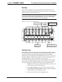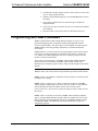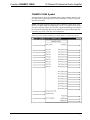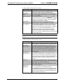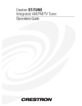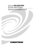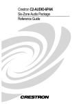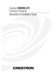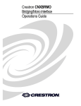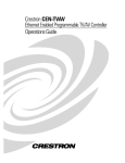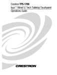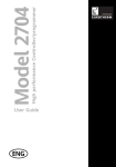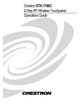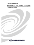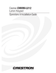
1
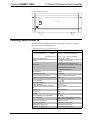
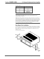
Crestron CNAMPX-16X60 16 Channel Professional Audio Amplifier Operations Guide This document was prepared and written by the Technical Documentation department at: Crestron Electronics, Inc. 15 Volvo Drive Rockleigh, NJ 07647 1-888-CRESTRON All brand names, product names and trademarks are the property of their respective owners. ©2000 Crestron Electronics, Inc. Crestron CNAMPX-16X60 16 Channel Professional Audio Amplifier Contents 16 Channel Professional Audio Amplifier: CNAMPX-16X60 1 Description................................................................................................................................. 1 Functional Description ................................................................................................ 1 Physical Description.................................................................................................... 1 Leading Specifications............................................................................................................... 5 Setup .......................................................................................................................................... 6 Network Wiring........................................................................................................... 6 Rack Mount Ear Installation........................................................................................ 7 Rack Mounting ............................................................................................................ 8 Hookup ........................................................................................................................ 9 Identity Code ............................................................................................................... 9 Programming with SIMPL Windows ...................................................................................... 10 CNAMPX-16X60 Symbol ........................................................................................ 11 Example Basic Touchpanel Pages............................................................................. 13 How the Example Program Works............................................................................ 14 Problem Solving ...................................................................................................................... 16 Troubleshooting......................................................................................................... 16 Further Inquiries ........................................................................................................ 17 Future Updates .......................................................................................................... 17 Return and Warranty Policies .................................................................................................. 18 Merchandise Returns / Repair Service ...................................................................... 18 CRESTRON Limited Warranty................................................................................. 18 Operations Guide – DOC. 8155 Contents • i Crestron CNAMPX-16X60 16 Channel Professional Audio Amplifier 16 Channel Professional Audio Amplifier: CNAMPX-16X60 Description Functional Description The CNAMPX-16X60 is a Crestron control network (Cresnet) 16 channel, 60Watts per channel audio amplifier. Typically installed in addition to the CNX-PAD8, the unit provides remote system power on/off and remote zone on/off capabilities. The CNAMPX-16X60 reports any electrical fault within itself or from a speaker load. The voltage from each speaker terminal is monitored and ambient temperature within the enclosure is reported via Cresnet and is available as Fahrenheit or Celsius. These signals can be used to reduce the audio volume, activate an external cooling fan, or turn the unit off under program control. All audio connectors are gold plated to prevent corrosion and five types of wire terminations can connect to the audio outputs. Highly efficient twin toroid transformers provide ample power to eight two-channel amplifier modules. The eight modules are of Crestron Detachable Modular Component (CDMC) design that allows rapid field repair. Each channel (two per module) of each module has its own power supply and filter capacitors that produce over 108,000 microFarads for enhanced dynamic range. The heat sinks of each channel contain more than 300 square inches of radiating surface allowing cooler operation. No fans are required but the unit must have a minimum of one rack space above and below for adequate ventilation. Physical Description The CNAMPX-16X60, shown on the next page, is housed in a black enclosure with silk-screened labels on the front and rear panels. The enclosure consists of 13-gauge powder-coated steel with stainless steel screws. The front panel contains the main power switch and light-emitting diode (LED). All audio input and output, Cresnet, and power connections are made on the rear panel. There are four rubber feet on the base of the unit for stability and to prevent slippage and two mounting ears with screws are provided for rack mounting. Operations Guide – DOC. 8155 16 Channel Professional Audio Amplifier: CNAMPX-16X60 • 1 16 Channel Professional Audio Amplifier Crestron CNAMPX-16X60 CNAMPX-16X60 Physical Views 1 2 3 4 5 6 7 8 LEFT PWR ROOM INPUTS NET RIGHT PRECAUCIÓN: ACHTUNG: ATTENTION: CAUTION: PARA LA PROTECCIÓN CONTINUADA CONTRA EL USO DEL AUFGRUND BRANDSCHUTZRECHTLICHER BESTIMMUNGEN, POUR LA PROTECTION CONTRE LES RISQUES D'INCENDIES FO R CONTINUED PROTECTION AGAINST FIRE RIESGO DE INCENDIOS USE SOLAMENTE EL MISMO TIPO Y BITTE NUR SICHERUNGEN DES SELBEN TYPS UND MIT DER N'UTILISEZ SEULEMENT LE MÊMES TYPE DE FUSIBLE. HAZARD USE ONLY SAME TYPE AND RATING FUSE. FUSIBLE DEL GRADO. DESCONECTE LA CUERDA DE LA SELBEN BELASTBRAKEIT VERWENDEN. TRENNEN SIE DAS DÉBRANCHEZ LE CÂBLE D'ALIMENTATION AVANT DE DISCO NNECT SUPPLY CORD BEFORE CHANGING FUSE. G ERAT VOM NETZ BEVOR SIE DIE SICHERUNG CHANGER LE FUSIBLE. FUENTE ANTES DE CAMBIAR EL FUSIBLE. NET CAUTION RISK OF ELECTRIC SHOCK 24 Y Z G DO NOT OPEN AVIS: RISQUE DE CHOC ELECTRIQUE NE PAS OUVRIR AUSTAUSCHEN. 1 2 3 4 5 6 7 8 OVERRIDE LEFT + - + - + - + - + - + - + - + - ROOM OUTPUTS 8 OHM / 60 WATTS 120V AC 60Hz 1800 WATTS MAX. 4 OHM / 90 WATTS 15A 125V RIGHT + - CRESTRON + - + ELECTRONICS INC., ROCKLEIGH, N.J. 07670 USA - + U.S .A - + - MADE IN THE USA + - + - + - DATE: 17.22 in (43.74 cm) 19.00 in (48.25 cm) 7.69 in (19.53 cm) POWER PROFESSIONAL 16 CHANNEL AUDIO AMPLIFIER 60 WATTS CRESTRON 2 • 16 Channel Professional Audio Amplifier: CNAMPX-16X60 CNAMPX-16X60 Operations Guide – DOC. 8155 Crestron CNAMPX-16X60 16 Channel Professional Audio Amplifier General Safety Precautions Read all information and instructions provided in this operations guide. Retain this operations guide. Heed all warnings and cautions printed in this operations guide. Follow all instructions in the order that they are provided. Do not use this unit near water. Clean only with a damp cloth. Do not block any of the ventilation openings. Install in accordance with the instructions in this operations guide. Do not install near any heat sources such as radiators, heat registers, stoves, or other apparatus that produce heat. If installing multiple CNAMPX-16X60s, follow the instructions provided in this operations guide. Do not defeat the safety purpose of the polarized or ground-type plug. A polarized plug has two blades with one wider that the other. A grounding type plug has two blades and a third grounding prong. The wide blade or the third prong is provided for your safety. When the provided plug does not fit into an outlet, consult an electrician for replacement of the obsolete outlet. Protect the power cord from being walked on or pinched particularly at plugs, convenience receptacles (if provided), and the point where they exit from the unit. Use only attachments/accessories specified in this operations guide. When an equipment rack is used, use caution when moving the rack/unit combination to avoid injury or tip-over. Unplug this unit during lighting storms or when unused for long periods of time. Refer all service to certified Crestron service personnel. Servicing is required when the unit has been damaged in a way, such as power cord or plug is damaged, liquid has been spilled or objects have fallen into the unit, the unit has been exposed to rain or moisture, does not operate normally, or has been dropped. CNAMPX-16X60 Rear Ports and Indicators A number of ports and indicators are provided on the rear of the CNAMPX-16X60. Refer to the illustration below and the descriptions on the next page. CNAMPX-16X60 Rear Panel 1 2 3 4 5 6 7 8 LEFT PWR ROOM INPUTS NET RIGHT PRECAUCIÓN: ACHTUNG: ATTENTION: CAUTION: PARA LA PROTECCIÓN CONTINUADA CONTRA EL USO DEL AUFGRUND BRANDSCHUTZRECHTLICHER BESTIMMUNGEN, POUR LA PROTECTION CONTRE LES RISQUES D'INCENDIES FOR CONTINUED PROTECTION AGAINST FIRE RIESGO DE INCENDIOS USE SOLAMENTE EL MISMO TIPO Y BITTE NUR SICHERUNGEN DES SELBEN TYPS UND MIT DER N'UTILISEZ SEULEMENT LE MÊMES TYPE DE FUSIBLE. HAZARD USE ONLY SAME TYPE AND RATING FUSE. FUSIBLE DEL GRADO. DESCONECTE LA CUERDA DE LA SELBEN BELASTBRAKEIT VERWENDEN. TRENNEN SIE DAS DÉBRANCHEZ LE CÂBLE D'ALIMENTATION AVANT DE DISCONNECT SUPPLY CORD BEFORE CHANGING FUSE. GERAT VOM NETZ BEVOR SIE DIE SICHERUNG CHANGER LE FUSIBLE. FUENTE ANTES DE CAMBIAR EL FUSIBLE. NET CAUTION RISK OF ELECTRIC SHOCK 24 Y Z G DO NOT OPEN AVIS: RISQUE DE CHOC ELECTRIQUE NE PAS OUVRIR AUSTAUSCHEN. 1 2 3 4 5 6 7 8 OVERRIDE LEFT + - + - + - + - + - + - + - + - ROOM OUTPUTS 8 OHM / 60 WATTS 120V AC 60Hz 1800 WATTS MAX. 4 OHM / 90 WATTS 15A 125V RIGHT + - CRESTRON Operations Guide – DOC. 8155 + - + ELECTRONICS INC., ROCKLEIGH, N.J. 07670 USA - + U.S .A - + MADE IN THE USA - + - + - + - DATE: 16 Channel Professional Audio Amplifier: CNAMPX-16X60 • 3 16 Channel Professional Audio Amplifier Crestron CNAMPX-16X60 PWR Indicator This LED (green) is illuminated when operating power is supplied to the CNAMPX16X60. NET Indicator This LED (yellow) indicates that the SIMPL program currently loaded in the control system has a network device defined at the same NET ID code as the CNAMPX16X60. The LED flashes when communication with the Cresnet system and the CNAMPX-16X60 is occurring. G (Chassis Ground) Use this chassis screw to connect the audio device(s) common ground(s) to the CNAMPX-16X60. NET The 4-pin network connector is used to connect the CNAMPX-16X60 to the Cresnet system. Review the Network Interconnection Diagram (latest revision of Doc. 5411). OVERRIDE Button and Indicator The OVERRIDE button is used to activate AC power to the CNAMPX-16X60 and activate all room outputs. This button functions only when 24VDC is applied to the NET connector. The LED (red) illuminates when the OVERRIDE is activated. Power Connector and Fuse Compartment The power connector provides AC operating power to the CNAMPX-16X60 via the supplied power cord. The fuse electrically protects the internal circuitry from power overloads and is located (a spare fuse is included) within the compartment above the power connector. CAUTION: If it becomes necessary to replace the fuse(s), replace only with same type, size and amperage rating. ROOM INPUTS 1 - 8 Each of the eight pair of RCA connectors is typically used to connect the preamplified audio from the CNX-PAD8 to the CNAMPX-16X60. The left channel audio is input to the connectors with the white center insulators and right channel audio connectors have red center insulators. ROOM OUTPUTS 1 – 8 These eight pair of speaker dual-binding posts output the left and right amplified audio to the corresponding speakers. The audio positive posts have RED screw-on caps and the audio negative posts have BLACK screw-on caps. Each post is goldplated and accepts bare wire, banana plugs, or spade lugs. CNAMPX-16X60 Front Panel Power Switch As shown on the next page, the front panel of the CNAMPX-16X60 contains a power switch with an LED indicator. This two-position (ON/OFF) switch enables operating power to the CNAMPX-16X60 circuitry and must be positioned to ON when the unit is controlled by the control system. When the Cresnet 24VDC is applied to the proper pin of the NET connector, power is applied to the circuitry and the LED (green) illuminates. 4 • 16 Channel Professional Audio Amplifier: CNAMPX-16X60 Operations Guide – DOC. 8155 Crestron CNAMPX-16X60 16 Channel Professional Audio Amplifier CNAMPX-16X60 Front Panel POWER PROFESSIONAL 16 CHANNEL AUDIO AMPLIFIER 60 WATTS CRESTRON CNAMPX-16X60 Leading Specifications The table below and continued on the next page provides a summary of leading specifications for the CNAMPX-16X60. Leading Specifications of the CNAMPX-16X60 SPECIFICATION Power Input Requirements: DETAILS US version 120VAC +/-10%, 50-60Hz, 1800 Watts International version 230VAC +/-10%, 50-60Hz, 1800 Watts Cresnet Power Requirements 24VDC @ .5A, 12 Watts Channels 16 grouped into 8 stereo pairs Output Power 60 Watts/Channel into 8 ohm loads, all channels driven, 20Hz to 20KHz, at rated THD 90 Watts/Channel into 4 ohm loads 220 Watts/Channel Bridged Input Impedance 28Kohms Power Bandwidth - 3dB 3Hz to 50KHz Frequency Response @ 1W 8ohm Flat +0, -0.1dB from 20Hz to 20KHz Total Harmonic Distortion (THD) @ full power 0.03% or less IHF I.M. Distortion 0.01% or less SMPTE I.M. Distortion 0.03% or less Dynamic Headroom 2dB or more Signal to Noise Ratio (S/N) "A" Weighted better than 110dB Gain 28dB Damping Factor Greater Than 1000 Rise Time Slue Rate Channel Separation over full bandwidth 2.2ms 25vms over 100dB SIMPL™ Windows® Version 1.40.07 or later 1 with the addition of smwlib87.exe and smwlib87.txt. 1 Version 2.1.8 or later. 1 Crestron VisionTools® Pro-e CEN-TVAV Upgrade File Operations Guide – DOC. 8155 Version 51013V.UPZ or later. 2 CNMXS-AV/Pro Upgrade File Version 51011X.UPZ or later. 2 CNRACKX/-DP Upgrade File Version 51011W.UPZ or later. 2 16 Channel Professional Audio Amplifier: CNAMPX-16X60 • 5 16 Channel Professional Audio Amplifier Crestron CNAMPX-16X60 Leading Specifications of the CNAMPX-16X60 (Continued) SPECIFICATION DETAILS Rack Space Required 4U Environmental Temperature Range Environmental Humidity 41 to 104o Fahrenheit (5 to 40o Celsius) 10% to 90% RH (non-condensing) Dimensions & Weight Height: 7.69 in (19.53 cm) Width: 19.00 in w/mounting ears (48.26 cm) Depth: 17.22 in (43.74 cm) Weight: 90.20 lb (41.00 kg) 1 The latest software versions can be obtained from the Downloads | Software Updates section of the Crestron website (www.crestron.com). Refer to the NOTE after the last footnote. 2 CNX update files are required for either CNMSX-AV/Pro or CNRACKX/-DP. Filenames for CNX update files have a UPZ extension and are in one EXE or zipped UPZ file. To avoid program problems, make certain you are using the update file with the correct suffix letter (e.g., V, W, X). NOTE: Crestron software and any files on the website are for Authorized Crestron dealers and Crestron Authorized Independent Programmers (CAIP) only. New users may be required to register to obtain access to certain areas of the site (including the FTP site). As of the date of manufacture, the CNAMPX-16X60 has been tested and found to comply with specifications for CE marking. NOTE: This device complies with part 15 of the FCC rules. Operation is subject to the following two conditions: (1) these devices may not cause harmful interference, and (2) these devices must accept any interference received, including interference that may cause undesired operation. Setup Network Wiring When calculating the wire gauge for a particular Cresnet run, the length of the run and the power factor of each network unit to be connected must be taken into consideration. If Cresnet units are to be daisy-chained on the run, the power factor of each unit to be daisy-chained must be added together to determine the power factor of the entire chain. If the unit is a home-run from a Crestron system power supply network port, the power factor of that unit is the power factor of the entire run. The length of the run in feet and the power factor of the run should be used in the following resistance equation to calculate the value on the right side of the equation. Resistance Equation R < 40,000 L x PF Where: R = Resistance (refer to table below). L = Length of run (or chain) in feet. PF = Power factor of entire run (or chain). The required wire gauge should be chosen such that the resistance value is less than the value calculated in the resistance equation. Refer to the table after this paragraph. 6 • 16 Channel Professional Audio Amplifier: CNAMPX-16X60 Operations Guide – DOC. 8155 Crestron CNAMPX-16X60 16 Channel Professional Audio Amplifier Wire Gauge Values RESISTANCE (R) WIRE GAUGE 4 16 6 18 10 20 15 22 13 Doubled CAT5 8.7 Tripled CAT5 NOTE: All Cresnet wiring must consist of two twisted-pairs. One twisted pair is the +24V conductor and the GND conductor and the other twisted pair is the Y conductor and the Z conductor. NOTE: When daisy-chaining Cresnet units, strip the ends of the wires carefully to avoid nicking the conductors. Twist together the ends of the wires that share a pin on the network connector, and tin the twisted connection. Apply solder only to the ends of the twisted wires. Avoid tinning too far up the wires or the end becomes brittle. Insert the tinned connection into the Cresnet connector and tighten the retaining screw. Repeat the procedure for the other three conductors. Rack Mount Ear Installation Two rack mount ears are provided with the CNAMPX-16X60 and must be installed prior to mounting. To attach the ears to the unit, position as shown below and install the provided screws finger-tight. With provided Allen key, tighten the screws an additional 1/8-turn. Ear Attachment for Rack Mounting Operations Guide – DOC. 8155 16 Channel Professional Audio Amplifier: CNAMPX-16X60 • 7 16 Channel Professional Audio Amplifier Crestron CNAMPX-16X60 Rack Mounting WARNING: To prevent bodily injury when mounting or servicing this unit in a rack, you must take special precautions to ensure that the system remains stable. The following guidelines are provided to ensure your safety: If the rack is provided with stabilizing devices, install the stabilizers before mounting or servicing the unit in the rack. WARNING: The CNAMPX-16X60 weighs in excess of 90 pounds. Use more than one person to install unit into rack. When mounting this unit in a partially filled rack, load the rack from the bottom to the top with the heaviest component at the bottom of the rack. The unit should be mounted at the bottom of the rack if it is the only unit in the rack. CAUTION: Due to the heat dissipation of the CNAMPX-16X60 (and all audio amplifiers in general), allow at least one free rack space above and below the CNAMPX-16X60 for proper circulation. Refer to the diagram after this note. CNAMPX-16X60 Rack Spacing NOTE: Reliable grounding of rack mounted equipment should be maintained. Particular attention should be given to supply connections other than direct connections to the branch circuit. (e.g., use of power strips). 8 • 16 Channel Professional Audio Amplifier: CNAMPX-16X60 Operations Guide – DOC. 8155 Crestron CNAMPX-16X60 16 Channel Professional Audio Amplifier Hookup Refer to the hookup diagram after this paragraph. Other than making the power connection last, complete the connections in any order. The power cord is supplied but RCA, speaker, or Cresnet cables are not. NOTE: If making four-wire connections to Cresnet devices, review the latest revision of the network interconnection drawing (Doc. 5411). The document can be obtained from the Downloads | Product Manuals section of the Crestron website (www.crestron.com). The name of the file is 5411i-cresnet.pdf. Hookup Connections for the CNAMPX-16X60 FROM CNX-PAD8 ROOM OUTPUTS 1 2 3 4 TO CNX-PAD8 GROUND SCREW TO CRESNET CONTROL SYSTEM 5 6 7 8 LEFT PWR ROOM INPUTS NET RIGHT PRECAUCIÓN: ACHTUNG: ATTENTION: CAUTION: PARA LA PROTECCIÓN CONTINUADA CONTRA EL USO DEL AUFGRUND BRANDSCHUTZRECHTLICHER BESTIMMUNGEN, POUR LA PROTECTION CONTRE LES RISQUES D'INCENDIES FOR CONTINUED PROTECTION AGAINST FIRE RIESGO DE INCENDIOS USE SOLAMENTE EL MISMO TIPO Y BITTE NUR SICHERUNGEN DES SELBEN TYPS UND MIT DER N'UTILISEZ SEULEMENT LE MÊMES TYPE DE FUSIBLE. HAZARD USE ONLY SAME TYPE AND RATING FUSE. FUSIBLE DEL GRADO. DESCONECTE LA CUERDA DE LA FUENTE ANTES DE CAMBIAR EL FUSIBLE. SELBEN BELASTBRAKEIT VERWENDEN. TRENNEN SIE DAS DÉBRANCHEZ LE CÂBLE D'ALIMENTATION AVANT DE GERAT VOM NETZ BEVOR SIE DIE SICHERUNG CHANGER LE FUSIBLE. NET CAUTION RISK OF ELECTRIC SHOCK 24 Y Z G DO NOT OPEN DISCONNECT SUPPLY CORD BEFORE CHANGING FUSE. AVIS: RISQUE DE CHOC ELECTRIQUE NE PAS OUVRIR AUSTAUSCHEN. 1 2 3 4 5 6 7 8 OVERRIDE LEFT + - + - + - + - + - + - + - + - ROOM OUTPUTS 8 OHM / 60 WATTS 120V AC 60Hz 1800 WATTS MAX. 4 OHM / 90 WATTS 15A 125V RIGHT + - CRESTRON + - + ELECTRONICS INC., ROCKLEIGH, N.J. 07670 USA - + U.S .A - + - MADE IN THE USA AUDIO TO SPEAKERS + - + - + - DATE: FROM AC OUTLET OR POWER STRIP Identity Code Every equipment and user interface within the Cresnet network requires a unique NET ID. These codes are recognized by a two-digit hexadecimal number from 03 to FE. The NET ID of the unit must match an ID code specified in the SIMPL Windows program. The NET ID of the CNAMPX-16X60 is factory set to 3D. The NET IDs of multiple CNAMPX-16X60 must all be unique and changed from a PC via SIMPL Windows or Crestron VisionTools Pro-e (VT Pro-e). The method for changing the unit’s NET ID is identical regardless of the software chosen. Attach one of the CNAMPX-16X60s to the control system (verify that the software is running) and complete the following steps to change the NET ID: Operations Guide – DOC. 8155 1. Disconnect all Cresnet devices from the control system, except for the unit that needs to have its NET ID changed. 2. Select Tools | Viewport to open the “Crestron Viewport” window. 3. Select Functions | Set Network ID. The software checks the baud rate and then opens the “Set Network ID” window. 4. In the “Set Network ID” window, highlight the unit. 16 Channel Professional Audio Amplifier: CNAMPX-16X60 • 9 16 Channel Professional Audio Amplifier Crestron CNAMPX-16X60 5. The NET ID of the unit appears in the box below the list. Use the scroll arrow to assign another NET ID. 6. When the assigned NET ID appears, select the Set ID button to initiate the change. 7. The software responds with a successful message to confirm the changed NET ID. 8. Observe the Viewport re-poll the network to verify that the NET ID has been changed. 9. Reconnect other Cresnet devices that were disconnected in step 1. Programming with SIMPL Windows SIMPL (Symbol Intensive Master Programming Language) is an easy-to-use programming language that is completely integrated and compatible with all Crestron system hardware. The objects that are used in SIMPL are called symbols. SIMPL Windows offers drag and drop functionality in a familiar Windows® environment. SIMPL Windows is Crestron's software for programming Crestron control systems. It provides a well-designed graphical environment with a number of workspaces (i.e., windows) in which a programmer can select, configure, program, test, and monitor a Crestron control system. The next three sections describe a CNAMPX-16X60 within a SIMPL Windows program. The first section details the SIMPL symbol and the second section describes how an example program works by using a textual description and a block diagram. NOTE: The following descriptions assume that the reader has knowledge of SIMPL Windows. If not, refer to the extensive help information provided with the software. NOTE: VT Pro-e is a Windows compatible software package for creating Crestron touchpanel screen designs. NOTE: VT Pro-e (version 2.1.8 or later) is required to produce the CNAMPX16X60 example touchpanel pages. The latest version of VT Pro-e can be obtained from the Downloads | Software Updates section of the Crestron website (www.crestron.com ). New users are required to register in order to obtain access to the FTP site. NOTE: There is no need to recreate the CNAMPX-16X60 example touchpanel pages or example SIMPL Windows program. Both are available from the Crestron FTP site (ftp://ftp.crestron /Examples). Search for CNAMPXEX.ZIP that contains CNAMPX-EX.SMW, CNAMPX-EX.VTP and associated macros required to complete the program. 10 • 16 Channel Professional Audio Amplifier: CNAMPX-16X60 Operations Guide – DOC. 8155 Crestron CNAMPX-16X60 16 Channel Professional Audio Amplifier CNAMPX-16X60 Symbol The diagram below shows the CNAMPX-16X60 symbol in SIMPL Windows. The two tables following the diagram list the inputs and outputs, respectively, and their functional descriptions. NOTE: All inputs listed in the following table are DIGITAL signals unless noted otherwise. A digital signal can be high (logic level of 1), low (logic level of 0), and also have rising edge (when it goes from low to high) and falling edge (from high to low) transitions. Depending upon how the symbol was created, symbol inputs may work at the logic levels, some may work on transitions. Detail View of the CNAMPX-16X60 Symbol in SIMPL Windows’ Programming Manager Operations Guide – DOC. 8155 16 Channel Professional Audio Amplifier: CNAMPX-16X60 • 11 16 Channel Professional Audio Amplifier Crestron CNAMPX-16X60 CNAMPX-16X60 Symbol Input Signal Descriptions INPUT(S) Main_Power Rm1 through Rm8_En Enable_Temp_Rpt Temp_Format Rm_To_Monitor DESCRIPTION(S) This signal activates the main operating power to the CNAMPX16X60 circuitry. High/1=power on, low/0=power off. These signals enable (or activate) the audio outputs for the corresponding amplifier module. High/1 = room is enabled, low/0 = room disabled. This signal selects whether or not the Temp(x10) analog output described in the next table is updated with the CNAMPX16X60 enclosure temperature. High/1 = update temperature, low/0/default = temperature not updated. This signal selects the format of the temperature to be displayed. High/1 = Celsius, low/0/default = Fahrenheit. This analog signal indicates the specific room for which the audio levels will be displayed. The room number to monitor corresponds to the value of the analog signal. For example, to monitor room 1, the value should be initialized to 1. The default is Room 0, which means monitoring is disabled. (Although the example program provides only the logic to monitor rooms 1 through 4, additional logic for rooms 5 through 9 may be programmed.) NOTE: All outputs listed in the following table are DIGITAL signals unless noted otherwise. CNAMPX-16X60 Symbol Output Signal Descriptions OUTPUT(S) OverRide_F Rm1 through Rm8_Amp_Fault Rm1 through Rm8_Wire_Fault Temp(x10) LeftSigLevel & RghtSigLevel DESCRIPTION(S) This signal indicates that the audio output override function is activated. High/1 = override active, low/0 = override not active. These signals indicate that there is an overcurrent or over temperature fault within the corresponding amplifier module. High/1 = fault is present, low/0 = fault present. (There is no sound when an amp fault is present. It will automatically attempt to reset after a short duration, attempting to turn the output on again.) These signals indicate that there is an error with the audio output wiring (or cables). High/1 = fault is present, low/0 = fault present. This only occurs after the amp fault has attempted to reset but fault still exists. This will not reset automatically. (The room must be turned off, problem resolved and then room turned on.) This analog signal corresponds to the ambient temperature within the CNAMPX-16X60 enclosure. The temperature reports approximately once every 2-seconds. (The Enable_temp_report entry in previous table must be driven high/1 for this to update.) These analog signals correspond to the audio level that is sent to a room. The specific room is determined by the Rm_To_Monitor input signal described in the previous table. The range of measurement is from 1 to 60 watts @ 8 ohms (0 to 100%). (These signals are for diagnostics and are not VU meters that function in real time.) 12 • 16 Channel Professional Audio Amplifier: CNAMPX-16X60 Operations Guide – DOC. 8155 Crestron CNAMPX-16X60 16 Channel Professional Audio Amplifier Example Basic Touchpanel Pages NOTE: VT Pro-e is required to produce the CNAMPX-16X60 example basic touchpanel pages. The latest version of VT Pro-e can be obtained from the Downloads | Software Updates section of the Crestron website (www.crestron.com). New users are required to register in order to obtain access to the FTP site. The example touchpanel page shown below is provided to demonstrate the basic capabilities of the CNAMPX-16X60. After selecting a room to control, the desired audio source is selected. Each source has a “Controls” subpage that is unique for the particular type of device. As shown, the jukebox that is available as an audio source can be programmed to skip to the next or previous track. Skipping to the next or previous disk can also be programmed as an available function. The audio volume can be increased, decreased or muted by the three buttons at the lower-left of the page. Pressing the button in the upper-right corner of the display accesses the CNAMPX-16X60 diagnostics page. Example Touchpanel Main Page Operations Guide – DOC. 8155 16 Channel Professional Audio Amplifier: CNAMPX-16X60 • 13 16 Channel Professional Audio Amplifier Crestron CNAMPX-16X60 The diagnostic page shown below may be used to monitor outputs of the CNAMPX16X60. The status of the override button is displayed, the circuitry of the eight amplifier modules is each monitored for electrical errors, and the output of each module is monitored for wire faults. The ambient temperature within the CNAMPX16X60 enclosure may be displayed and the audio level (rooms 1 through 4 for this example) can be monitored. Pressing the BACK button in the lower-left corner of the display returns the display to the main page. Example Touchpanel Diagnostic Page How the Example Program Works The example SIMPL program for the CNAMPX-16X60 is shown on the next page as a block diagram. The diagram shows only the components and logic associated with example touchpanel. The actual program involves extensive CNX-PAD8 logic and certain inputs and outputs have been rearranged or omitted for clarity. In the block diagram, the signals labeled A through F are feedback to the touchpanel. 14 • 16 Channel Professional Audio Amplifier: CNAMPX-16X60 Operations Guide – DOC. 8155 Crestron CNAMPX-16X60 16 Channel Professional Audio Amplifier Example CNAMPX-16X60 SIMPL Program Operations Guide – DOC. 8155 16 Channel Professional Audio Amplifier: CNAMPX-16X60 • 15 16 Channel Professional Audio Amplifier Crestron CNAMPX-16X60 Problem Solving Troubleshooting The table below provides corrective action for possible trouble situations. If further assistance is required, please contact a Crestron customer service representative. CNAMPX-16X60 Troubleshooting TROUBLE POSSIBLE CAUSE(S) CORRECTIVE ACTION Verify that POWER switch is positioned to ON, AC power cord is plugged into CNAMPX-16X60 power port and cord is plugged into a good power source. Replace fuse. CNAMPX-16X60 is not Verify that 24VDC is present at cable plugged receiving 24VDC Cresnet into NET port. power. Green PWR LED CNAMPX-16X60 in Verify SIMPL Windows CNAMPX-16X60 does not illuminate. SIMPL Windows program program. not properly configured. No functions and no indicators illuminate. CNAMPX-16X60 is not receiving VAC power. CNAMPX-16X60 is not Verify that 24VDC is present at cable plugged receiving 24VDC Cresnet into NET port. power. Yellow NET LED Improper NET ID. does not illuminate. Verify that CNAMPX-16X60 NET ID matches NET ID in software program. Hum on audio. Audio is supplied to all rooms regardless of programming. Audio distorted or not present at one room output. Grounding problem. Override function selected. Either connect or remove chassis ground wire. Press OVERRIDE button on rear panel of CNAMPX-16X60. Audio input cable(s) loose or not connected. Verify that audio input cable(s) plugged into ROOM INPUTS port(s) are secure. Room output (speaker) wire(s) loose or not connected. CNAMPX-16X60 has detected a wire fault at the room output. Verify that speaker wire(s) connected to ROOM OUTPUTS terminal(s) are secure. Amplifier module faulty. Refer to "CNAMPX-16X60 Service Guide" to replace module. * From control system, turn room output off, correct speaker wiring (or replace shorted speaker), and turn room output back on to reset fault. CNX-PAD8 not operating Refer to "CNX-PA8 Operations Guide" for properly. troubleshooting. * * For further instructions, refer to the latest revisions of the CNAMPX-16X60 Service Guide (Doc. 5885) or the CNX-PAD8 Operations Guide (Doc. 8137). These documents can be obtained from the Downloads | Product Manuals section of the Crestron website (www.crestron.com ). The name of the files is cnampx-12x60_16x60-service.pdf and cnx-pad8.pdf, respectively. 16 • 16 Channel Professional Audio Amplifier: CNAMPX-16X60 Operations Guide – DOC. 8155 Crestron CNAMPX-16X60 16 Channel Professional Audio Amplifier Further Inquiries If after reviewing this Operations Guide for the CNAMPX-16X60, you cannot locate specific information or have questions, please take advantage of Crestron's award winning customer service team by calling: • In the US and Canada, call Crestron’s corporate headquarters at 1-888-CRESTRON [1-888-273-7876]. • In Europe, call Crestron International at +32-15-50-99-50. • In Asia, call Crestron Asia at +852-2341-2016. • In Latin America, call Crestron Latin America at +5255-5093-2160. • In Australia and New Zealand, call Crestron Pacific at +613-9480-2999. Future Updates As Crestron improves functions, adds new features, and extends the capabilities of the CNAMPX-16X60, additional information and programming examples may be made available as manual updates. These updates are solely electronic and serve as intermediary supplements prior to the release of a complete technical documentation revision. Check the Crestron website (www.crestron.com) periodically for manual update availability and its subjective value. Updates are available from the Download | Product Manuals section and are identified as an “Addendum” in the Download column. Operations Guide – DOC. 8155 16 Channel Professional Audio Amplifier: CNAMPX-16X60 • 17 16 Channel Professional Audio Amplifier Crestron CNAMPX-16X60 Return and Warranty Policies Merchandise Returns / Repair Service 1. No merchandise may be returned for credit, exchange, or service without prior authorization from CRESTRON. To obtain warranty service for CRESTRON products, contact the factory and request an RMA (Return Merchandise Authorization) number. Enclose a note specifying the nature of the problem, name and phone number of contact person, RMA number, and return address. 2. Products may be returned for credit, exchange, or service with a CRESTRON Return Merchandise Authorization (RMA) number. Authorized returns must be shipped freight prepaid to CRESTRON, Cresskill, N.J., or its authorized subsidiaries, with RMA number clearly marked on the outside of all cartons. Shipments arriving freight collect or without an RMA number shall be subject to refusal. CRESTRON reserves the right in its sole and absolute discretion to charge a 15% restocking fee, plus shipping costs, on any products returned with an RMA. 3. Return freight charges following repair of items under warranty shall be paid by CRESTRON, shipping by standard ground carrier. In the event repairs are found to be non-warranty, return freight costs shall be paid by the purchaser. CRESTRON Limited Warranty CRESTRON ELECTRONICS, Inc. warrants its products to be free from manufacturing defects in materials and workmanship under normal use for a period of three (3) years from the date of purchase from CRESTRON, with the following exceptions: disk drives and any other moving or rotating mechanical parts, pan/tilt heads and power supplies are covered for a period of one (1) year; touchscreen display and overlay components are covered for 90 days; batteries and incandescent lamps are not covered. This warranty extends to products purchased directly from CRESTRON or an authorized CRESTRON dealer. Purchasers should inquire of the dealer regarding the nature and extent of the dealer's warranty, if any. CRESTRON shall not be liable to honor the terms of this warranty if the product has been used in any application other than that for which it was intended, or if it has been subjected to misuse, accidental damage, modification, or improper installation procedures. Furthermore, this warranty does not cover any product that has had the serial number altered, defaced, or removed. This warranty shall be the sole and exclusive remedy to the original purchaser. In no event shall CRESTRON be liable for incidental or consequential damages of any kind (property or economic damages inclusive) arising from the sale or use of this equipment. CRESTRON is not liable for any claim made by a third party or made by the purchaser for a third party. CRESTRON shall, at its option, repair or replace any product found defective, without charge for parts or labor. Repaired or replaced equipment and parts supplied under this warranty shall be covered only by the unexpired portion of the warranty. Except as expressly set forth in this warranty, CRESTRON makes no other warranties, expressed or implied, nor authorizes any other party to offer any warranty, including any implied warranties of merchantability or fitness for a particular purpose. Any implied warranties that may be imposed by law are limited to the terms of this limited warranty. This warranty statement supercedes all previous warranties. Trademark Information All brand names, product names, and trademarks are the sole property of their respective owners. Windows is a registered trademark of Microsoft Corporation. Windows 95/98/Me/XP and Windows NT/2000 are trademarks of Microsoft Corporation. 18 • 16 Channel Professional Audio Amplifier: CNAMPX-16X60 Operations Guide – DOC. 8155 Crestron CNAMPX-16X60 16 Channel Professional Audio Amplifier This page intentionally left blank. Operations Guide – DOC. 8155 16 Channel Professional Audio Amplifier: CNAMPX-16X60 • 19 Crestron Electronics, Inc. 15 Volvo Drive Rockleigh, NJ 07647 Tel: 888.CRESTRON Fax: 201.767.7576 www.crestron.com Operations Guide – DOC. 8155 06.00 Specifications subject to change without notice.