1
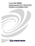
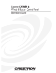
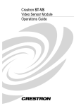
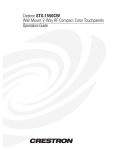
This document was prepared and written by the Technical Documentation department at:
Crestron Electronics, Inc.
15 Volvo Drive
Rockleigh, NJ 07647
1-888-CRESTRON
Crestron DA-1550CW
Docking Assembly for STX-1550CW
Contents
Docking Assembly for STX-1550CW: DA-1550CW
Description
Functional Description
Physical Description
Leading Specifications
Setup
Network Wiring
Identity Code
Installation
Programming with SIMPL Windows
Configure DA-1550CW Program
BB/DA-1550CW Symbol
Example Program
Operation
Normal Operation
Manual Undocking of Touchpanel
Problem Solving
Troubleshooting
Further Inquiries
Future Updates
Return and Warranty Policies
Merchandise Returns / Repair Service
CRESTRON Limited Warranty
Operations & Installation Guide - DOC. 5930
1
1
1
1
4
4
4
5
6
8
9
9
10
10
10
12
15
15
17
17
18
18
18
Contents • i
Crestron DA-1550CW
Docking Assembly for STX-1550CW
Docking Assembly for
STX-1550CW: DA-1550CW
Description
Functional Description
The DA-1550CW docking assembly is wall-mounted hardware that is used to dock a
Crestron SmarTouch STX-1550CW compact color touchpanel. Used with the
BB-1550CW back box (sold separately), the DA-1550CW provides operating power,
hard-wire communications with a standard Crestron remote control system (herein
referred to as the Cresnet system), and recharges the Crestron High Performance
Rechargeable Power Pack (ST-BTP) of the docked touchpanel.
The DA-1550CW unlatches the STX-1550CW electrically via the control system
program. When the touchpanel is unlatched, it snaps outward slightly, and then may
be removed by hand. The control system program defines the method of unlatching.
Provisions have also been incorporated to allow the touchpanel to be unlatched
manually. When not docked in the DA-1550CW, the touchpanel is a handheld, long
range, 2-way radio frequency (RF) wireless transceiver that communicates through a
RF transceiver/gateway, STRFGWX (sold separately) to the Cresnet system.
Physical Description
Refer to the diagrams on the next two pages. The physical views diagram provides
overall dimensions of the DA-1550CW. The front view of the DA-1550CW shows
the two mechanical hooks used to latch the touchpanel and six electrical contacts.
The upper two electrical contacts are for Cresnet system Y and Z data signals and the
remaining four contacts supply touchpanel operating power and ST-BTP recharging.
The side view diagram shows the manual unlatch tab (accessible through the
supplied decorative faceplate), the latching lever and hooks, and the electrical
unlatch solenoid. At the rear of the DA-1550CW is the standard Cresnet 4-wire,
network port. The port provides the Cresnet 24 volts direct current (VDC) operating
power, communications, and ST-BTP recharging power to the DA-1550CW.
Supplied with the DA-1550CW, but not shown, are a decorative front panel, manual
unlatch access hole plug (part number GGHP0R2180-1) and four hex screws (part
number SR06-32-0R3750-12). Four Phillips screws (SR06-32-0R2500-8) to secure
the unit to the BB-1550CW back box are also supplied.
Operations & Installation Guide - DOC. 5930
Docking Assembly for STX-1550CW: DA-1550CW • 1
Docking Assembly for STX-1550CW
Crestron DA-1550CW
DA-1550CW Physical Views and Dimensions
5.57 in
(14.14 cm)
3.56 in
(9.05 cm)
6.51 in
(16.54 cm)
Front View Components
TOUCHPANEL
LATCHING
HOOKS
ELECTRICAL
CONTACTS
(CRESNET
Y DATA & Z DATA)
ELECTRICAL
CONTACTS
(OPERATING &
RECHARGE POWER)
2 • Docking Assembly for STX-1550CW: DA-1550CW
Operations & Installation Guide - DOC. 5930
Crestron DA-1550CW
Docking Assembly for STX-1550CW
Side View (with Partial Cut-Away) Components
MANUAL
UNLATCH
TAB
LATCHING
LEVER & HOOKS
UNLATCH
SOLENOID
SOLENOID
ELECTRICAL
CONNECTORS
Rear View Components
LATCH
RETURN
SPRING
UNLATCH
LEVER
CRESNET
CONNECTOR
Operations & Installation Guide - DOC. 5930
Docking Assembly for STX-1550CW: DA-1550CW • 3
Docking Assembly for STX-1550CW
Crestron DA-1550CW
Leading Specifications
The table below provides a summary of leading specifications for the DA-1550CW.
Dimensions and weight are rounded to the nearest hundredth unit.
Leading Specifications of the DA-1550CW
SPECIFICATION
Power Requirements
Default Network ID
SIMPL™ Windows®
CEN-CN Update File
CEN/CN-TVAV Update File
CNMSX-AV/Pro Update File
CNRACKX/-DP Update File
Dimensions & Weight
DETAILS
34 Watts (1.4 Amps @ 24 VDC)
51
Version 1.52.01 or later 1
Version 5.11.80N.UPZ or later 2
Version 5.11.40V.UPZ or later 2
Version 5.10.11X.UPZ or later 2
Version 5.10.11W.UPZ or later 2
Height: 6.51 in (16.54 cm)
Width: 5.57 in (14.14 cm)
Depth: 3.56 in (9.05 cm)
Weight: 3.21 lb (1.46 kg)
1
In version 1.52.01 of SIMPL Windows, the BB/DA-1550CW symbol is referred to
as the BB-1550CW. Additionally, the input of the symbol is labeled “Unlatch” and
the corresponding output is labeled “Unlock-FB”. SIMPL Windows version prior to
1.52.01 that have a BB-1550CW device should be upgraded to 1.52.01 or later.
Although the functionality of the symbol is identical, later versions have re-named
the device to BB/DA-1550CW, the symbol input changed to “Unlatch” and the
output labeled “Unlatched”. The latest version can be obtained from the Downloads
page (SIMPLWIN Library) of Crestron’s website (www.crestron.com). New users
are required to register in order to obtain access to the FTP site.
2
Filenames for update files have a UPZ extension and can be obtained from the
Downloads page (OPSYS Library) of Crestron’s website.
As of the date of manufacture, this unit has been tested and found to comply with
specifications for CE marking.
NOTE: This device complies with part 15 of the FCC rules. Operation is subject to
the following two conditions: (1) this device may not cause harmful interference, and
(2) this device must accept any interference received, including interference that may
cause undesired operation.
Setup
Network Wiring
NOTE: If making four-wire connections to Cresnet devices, review the latest
revision of the network interconnection drawing (Doc. 5411). The document can be
obtained from the Downloads page (CABLES and MANUAL Libraries) of
Crestron’s website (www.crestron.com). Search for CRESNET.PDF. New users are
required to register in order to obtain access to the FTP site.
4 • Docking Assembly for STX-1550CW: DA-1550CW
Operations & Installation Guide - DOC. 5930
Crestron DA-1550CW
Docking Assembly for STX-1550CW
When calculating the wire gauge for a particular Cresnet run, the length of the run
and the load factor of each network unit to be connected must be taken into
consideration. If Cresnet units are to be daisy-chained on the run, the load factor of
each unit to be daisy-chained must be added together to determine the load factor of
the entire chain. If the unit is a home-run from a Crestron system power supply
network port, the load factor of that unit is the load factor of the entire run. The
length of the run in feet and the load factor of the run should be used in the following
resistance equation to calculate the value on the right side of the equation.
Resistance Equation
R
<
4 0 ,0 0 0
L x LF
W h e re: R = R e s ista n c e ( refer to next table).
L = L e n g t h o f r u n ( o r c h a i n ) in fe e t .
L F = L o a d fa c to r o f e n t i r e r u n ( o r c h a i n ) .
The required wire gauge should be chosen such that the resistance value is less than
the value calculated in the resistance equation. Refer to the table below.
Wire Gauge Values
RESISTANCE (R)
WIRE GAUGE
4
6
10
15
16
18
20
22
NOTE: All Cresnet wiring must consist of two twisted-pairs. One twisted pair is the
+24V conductor and the GND conductor and the other twisted pair is the Y
conductor and the Z conductor.
NOTE: When daisy-chaining Cresnet units, always twist the ends of the incoming
wire and outgoing wire which share a pin on the network connector. After twisting
the ends, tin the twisted connection with solder. Apply solder only to the ends of the
twisted wires. Avoid tinning too far up the wires or the end becomes brittle. After
tinning the twisted ends, insert the tinned connection into the Cresnet connector and
tighten the retaining screw. Repeat the procedure for the other three conductors.
Identity Code
Every user interface within the Cresnet system requires a unique network identity
code (NET ID). These codes are recognized by a two-digit hexadecimal number
from 03 to FE. The NET ID of the DA-1550CW must match an ID code specified in
the SIMPL Windows program. The NET ID of the DA-1550CW is factory set to 51.
The NET IDs of multiple DA-1550CWs must be unique and changed from a
personal computer (PC) via VisionTools™ Pro-e (VT Pro-e) or SIMPL Windows.
NOTE: VT Pro-e is a Windows compatible software package for creating Crestron
touchpanel screen designs.
NOTE: In version 1.52.01 of SIMPL Windows, the BB/DA-1550CW symbol is
referred to as the BB-1550CW. Additionally, the input of the symbol is labeled
“Unlock” and the corresponding output is labeled “Unlock-FB”. SIMPL Windows
version prior to 1.52.01 that have a BB-1550CW device should be upgraded to
1.52.01 or later. Although the functionality of the symbol is identical, later versions
have re-named the device to BB/DA-1550CW, the symbol input changed to
Operations & Installation Guide - DOC. 5930
Docking Assembly for STX-1550CW: DA-1550CW • 5
Docking Assembly for STX-1550CW
Crestron DA-1550CW
“Unlatch” and the output labeled “Unlatched”. The latest version can be obtained
from the Downloads page (SIMPLWIN Library) of Crestron’s website
(www.crestron.com). New users are required to register in order to obtain access to
the FTP site.
The method for changing the unit’s NET ID is identical regardless of the software
chosen. Attach one of the DA-1550CWs to the control system (verify that the
software is running) and complete the following steps to change the NET ID.
1.
Disconnect all Cresnet devices from the control system, except for the
DA-1550CW that needs to have its NET ID changed.
2.
Select Tools | Viewport to open the “Crestron Viewport” dialog box.
3.
Select Functions | Set Network ID. The software checks the baud rate
and then opens the “Set Network ID” dialog box.
4.
In the “Set Network ID” dialog box, select the BB-1550CW from the
Current Network Devices text window.
5.
From the Choose the new network ID for the selected device (Hex):
drop-down list, select the new Net ID for the DA-1550CW.
6.
Click the Set ID button to initiate the change. This should display the
confirmation message, “ID command has been sent”.
7.
Select Diagnostics | Report Network Devices to verify that the
DA-1550CW has a new NET ID code.
8.
Reconnect other Cresnet devices that were disconnected in step 1.
Installation
To install the DA-1550CW, complete the following installation procedure in the
order provided. The only tools required are a #2 Phillips screwdriver and a 5/64-inch
hex wrench.
NOTE: This procedure is performed only after the BB-1550CW back box has been
installed. Make sure that the back box is installed inward of the face of the gypsum
board to accommodate the distance between the back box and the front panel. For
further information, refer to the latest revision of the BB-1550CW Installation Guide
(Doc. 5848). The latest version can be obtained from the Downloads page
(MANUAL Library) of Crestron’s website (www.crestron.com). New users are
required to register in order to obtain access to the FTP site.
1.
Position the DA-1550CW to the back box and connect the Cresnet
wiring to the rear port. Refer to “Network Wiring” on page 4, if
necessary.
2.
As shown on the next page, position the DA-1550CW into the back
box. Install four Phillips screws (supplied) to finger-tight then, using a
#2 Phillips screwdriver, tighten an additional 1/8-turn.
6 • Docking Assembly for STX-1550CW: DA-1550CW
Operations & Installation Guide - DOC. 5930
Crestron DA-1550CW
Docking Assembly for STX-1550CW
Install DA-1550CW
3.
As shown below, position the front panel to the DA-1550CW. Install
four hex screws (supplied) to finger-tight then, using a 5/64-inch hex
wrench, tighten an additional 1/8-turn.
Install Front Panel
Operations & Installation Guide - DOC. 5930
Docking Assembly for STX-1550CW: DA-1550CW • 7
Docking Assembly for STX-1550CW
4.
Crestron DA-1550CW
As shown below, install the access hole plug into the access hole.
Install Access Hole Plug
Programming with SIMPL Windows
SIMPL (Symbol Intensive Master Programming Language) is an easy-to-use
programming language that is completely integrated and compatible with all
Crestron system hardware. The objects that are used in SIMPL are called symbols.
SIMPL Windows offers drag and drop functionality in a familiar Windows®
environment.
SIMPL Windows is Crestron's software for programming Crestron control systems.
It provides a well-designed graphical environment with a number of workspaces
(i.e., windows) in which a programmer can select, configure, program, test, and
monitor a Crestron control system.
NOTE: The following descriptions assume that the reader has knowledge of SIMPL
Windows. If not, refer to the extensive help information provided with the software.
NOTE: In version 1.52.01 of SIMPL Windows, the BB/DA-1550CW symbol is
referred to as the BB-1550CW. Additionally, the input of the symbol is labeled
“Unlock” and the corresponding output is labeled “Unlock-FB”. SIMPL Windows
version prior to 1.52.01 that have a BB-1550CW device should be upgraded to
1.52.01 or later. Although the functionality of the symbol is identical, later versions
have re-named the device to BB/DA-1550CW, the symbol input changed to
“Unlatch” and the output labeled “Unlatched”. The latest version can be obtained
from the Downloads page (SIMPLWIN Library) of Crestron’s website
(www.crestron.com). New users are required to register in order to obtain access to
the FTP site.
8 • Docking Assembly for STX-1550CW: DA-1550CW
Operations & Installation Guide - DOC. 5930
Crestron DA-1550CW
Docking Assembly for STX-1550CW
Configure DA-1550CW Program
To create a program with a DA-1550CW, refer to the table below for initial
configuration information.
NOTE: Multiple DA-1550CWs may be used with a single control system. To use
multiple DA-1550CWs , refer to “Identity Code” that begins on page 5.
Configure DA-1550CW Program
SYMBOL
FOLDER
SYMBOL
REQUIRED
Device Library, Desired control
Control
system
Systems
DROP
WHERE
System Views
Device Library, BB/DA-1550CW System Views,
Network Control (Earlier versions Cresnet Units
of SIMPL
Modules
Windows have BB1550CW.)
ADDITIONAL
SETUP
Refer to the documentation
supplied with the specific
control system for additional
setup information.
OPTIONAL CHANGE ID Double-click on BB/DA1550CW or single-click then
right mouse-click on BB/DA1550CW, select Configure.
BB/DA-1550CW Symbol
The diagram below shows the BB/DA-1550CW symbol in SIMPL Windows. The
two tables on the next page list the inputs and outputs, respectively, and their
functional descriptions.
Detail View of the BB/DA-1550CW Symbol in SIMPL Windows’ Programming Manager
NOTE: All signals listed in the tables on the next page are DIGITAL signals unless
noted otherwise. A digital signal can be high (logic level of 1), low (logic level of 0),
and also have rising edge (when it goes from low to high) and falling edge (from
high to low) transitions. Depending upon how the symbol was created, symbol
signals may work at the logic levels, some may work on transitions.
Operations & Installation Guide - DOC. 5930
Docking Assembly for STX-1550CW: DA-1550CW • 9
Docking Assembly for STX-1550CW
Crestron DA-1550CW
BB/DA-1550CW Symbol Input Description
INPUT
UNLATCH
(Unlock in earlier
versions of SIMPL
Windows.)
FUNCTION(S)
Edge sensitive. Unlatches the back box for 5-seconds when the
edge of the signal is received. After the 5-seconds has expired,
the latch engages. The back box may not be unlatched for
1-second after the latch is engaged.
BB/DA-1550CW Symbol Output Descriptions
OUTPUTS
FUNCTION(S)
UNLATCHED
1 when the latch is open, 0 when the latch is closed.
(Unlock-FB in earlier
versions of SIMPL
Windows.)
PANELPRESENT
1 when the touchpanel is docked, 0 when the touchpanel is not
docked.
1 when the touchpanel is docked and the ST-BTP is charging,
CHARGING
0 otherwise (i.e. done charging, touchpanel not docked).
1 when the touchpanel is docked and charging is complete, 0
CHARGEDONE
otherwise (i.e. still charging, touchpanel not present).
1 when there is a charge fault (i.e. hardware problem with the
CHARGEFAULT
touchpanel, poor contact with the charger, a network voltage
problem, etc.), 0 when no fault is present.
Example Program
An example program for the DA-1550CW is available from the Downloads page
(EXAMPLES Library) of Crestron’s website (www.crestron.com). Search for
DA1550CW.ZIP that contains the example program, associated files and a
README.TXT file that describes the program. New users are required to register in
order to obtain access to the FTP site.
Operation
The DA-1550CW docks the STX-1550CW touchpanel, provides power and
communication, and recharges the ST-BTP. Operation consists of docking the
touchpanel (performed by hand) into the DA-1550CW or undocking electrically via
the control system and then removing by hand. Provisions have also been
incorporated to allow the touchpanel to be undocked manually.
Normal Operation
Normal operation of the DA-1550CW is described in the next two sections.
Docking the STX-1550CW
Docking of the STX-1550CW is performed by hand by inserting the bottom edge of
the touchpanel into the DA-1550CW and snapping it into place. To dock the
touchpanel, refer to the procedure on the next page.
NOTE: Do not dock the STX-1550CW into the DA-1550CW without the ST-BTP
being installed in the touchpanel. Operating power for the DA-1550CW is supplied
through the electrical contacts of the ST-BTP. If the ST-BTP is not installed, the
DA-1550CW will not electrically unlatch the touchpanel.
10 • Docking Assembly for STX-1550CW: DA-1550CW
Operations & Installation Guide - DOC. 5930
Crestron DA-1550CW
Docking Assembly for STX-1550CW
1.
Refer to the diagram below. Insert the bottom edge of touchpanel
docking plate (located on the rear of the touchpanel) into DA-1550CW
directly behind the front panel.
Insert STX-1550CW
2.
Refer to the diagram below. Make sure that the STX-1550CW is
squarely seated in DA-1550CW and press upper edge of touchpanel
inward to dock the touchpanel. The touchpanel will snap into position.
Dock STX-1550CW
Operations & Installation Guide - DOC. 5930
Docking Assembly for STX-1550CW: DA-1550CW • 11
Docking Assembly for STX-1550CW
Crestron DA-1550CW
Undocking the STX-1550CW
During normal operation, the DA-1550CW unlatches the STX-1550CW electrically
via the control system program. When the touchpanel is unlatched, it snaps outward
slightly, and then may be removed by hand. The control system program defines the
method (i.e., touchpanel button) of unlatching.
NOTE: For further information about the touchpanel and programming the unlatch
method, refer to the latest revision of the STX-1550CW Operations Guide (Doc.
5849). The latest version can be obtained from the Downloads page (MANUAL
Library) of Crestron’s website (www.crestron.com). New users are required to
register in order to obtain access to the FTP site.
1.
Via the touchpanel and/or control system program, unlatch the
touchpanel.
2.
Refer to the diagram below. By hand, undock the touchpanel by pulling
the upper edge of the touchpanel outward and remove the touchpanel.
Remove STX-1550CW
Manual Undocking of Touchpanel
If the DA-1550CW does not unlatch the STX-1550CW electrically, provisions have
been incorporated to allow the touchpanel to be undocked manually. The only tool
required is a long-reach (minimum 4-1/2 inches from tip to handle base) #1 flat or
Phillips screwdriver.
12 • Docking Assembly for STX-1550CW: DA-1550CW
Operations & Installation Guide - DOC. 5930
Crestron DA-1550CW
Docking Assembly for STX-1550CW
1.
Refer to the diagram below. At top-center of the front panel, remove
the manual unlatch access plug from the access hole.
Remove Access Hole Plug
2.
As shown below, insert a long-reach screwdriver into the access hole at
a downward angle (approximately 10o) until the tip of the screwdriver
contacts the manual unlatch tab.
Insert Screwdriver
Operations & Installation Guide - DOC. 5930
Docking Assembly for STX-1550CW: DA-1550CW • 13
Docking Assembly for STX-1550CW
3.
Crestron DA-1550CW
As shown below, lower the handle of the screwdriver until the
touchpanel unlatches (handle of screwdriver will be approximately
level and touchpanel will snap outward slightly).
Lower Screwdriver Handle
4.
Refer to the diagram below. By hand, undock the touchpanel by pulling
the upper edge of the touchpanel outward and remove the touchpanel.
Remove STX-1550CW
14 • Docking Assembly for STX-1550CW: DA-1550CW
Operations & Installation Guide - DOC. 5930
Crestron DA-1550CW
Docking Assembly for STX-1550CW
5.
Refer to the diagram below. Re-install the access hole plug into the
access hole.
Re-Install Access Hole Plug
Problem Solving
Troubleshooting
The table below and continued on the next page provides corrective action for
possible trouble situations. If further assistance is required, please contact a Crestron
customer service representative.
DA-1550CW Troubleshooting
TROUBLE
DA-1550CW
does not
unlatch
touchpanel.
Operations & Installation Guide - DOC. 5930
POSSIBLE
CAUSE(S)
CORRECTIVE ACTION
Touchpanel not
properly docked.
Adjust touchpanel to make sure that
touchpanel is squarely seated in DA-1550CW
and fully snapped into position.
ST-BTP not installed in Perform "Manual Undocking of Touchpanel"
touchpanel.
and install ST-BTP. 1
Electrical contacts dirty. Perform "Manual Undocking of Touchpanel"
then clean contacts.
BB/DA-1550CW NET From the Viewport (in SIMPL Windows or VT
ID does not match NET Pro-e), verify that NET IDs match.
ID set in SIMPL
program.
BB/DA-1550CW in
Verify SIMPL Windows BB/DA-1550CW
SIMPL Windows
program.
program not configured
properly.
Cresnet connector not Perform "Manual Undocking of Touchpanel",
secure.
perform "Installation" in reverse & check that
Solenoid connector not connector is secure.
secure.
Docking Assembly for STX-1550CW: DA-1550CW • 15
Docking Assembly for STX-1550CW
Crestron DA-1550CW
DA-1550CW Troubleshooting (continued)
TROUBLE
POSSIBLE
CAUSE(S)
CORRECTIVE ACTION
DA-1550CW BB/DA-1550CW in
does not dock SIMPL Windows
touchpanel. program not configured
properly.
Mechanical binding in
DA-1550CW.
Touchpanel ST-BTP not installed in
touchpanel.
does not
communicate Electrical contacts of
with Cresnet DA-1550CW dirty.
when docked. BB/DA-1550CW NET
ID does not match NET
ID set in SIMPL
program.
BB/DA-1550CW in
SIMPL Windows
program not configured
properly.
Cresnet connector not
secure.
ST-BTP contacts of
docking terminal dirty.
ST-BTP cannot retain
charge.
Cresnet connector not
secure.
Back box enclosure
Front panel
not flush with clearance not adjusted
properly.
wall.
ST-BTP of
touchpanel
does not
recharge.
Verify SIMPL Windows BB/DA-1550CW
program.
Perform "Installation" in reverse then check
assembly.
Perform "Manual Undocking of Touchpanel"
and install ST-BTP. 1
Perform "Manual Undocking of Touchpanel"
then clean contacts.
From the Viewport (in SIMPL Windows or VT
Pro-e), verify that NET IDs match.
Verify SIMPL Windows BB/DA-1550CW
program.
Perform "Manual Undocking of Touchpanel",
perform "Installation" in reverse & check that
connector is secure.
Undock touchpanel then clean contacts.
Undock touchpanel then replace ST-BTP.
Undock touchpanel, perform "Installation" in
reverse & check that connector is secure.
Undock touchpanel, refer to BB-1550CW
Installation Guide & re-adjust enclosure
clearance. 2
1
For further information, refer to the latest revision of the ST-BTP Installation Guide
(Doc. 5746). The latest version can be obtained from the Downloads page
(MANUAL Library) of Crestron’s website (www.crestron.com). New users are
required to register in order to obtain access to the FTP site.
2
For further information, refer to the latest revision of the BB-1550CW Installation
Guide (Doc. 5848). The latest version can be obtained from the Downloads page
(MANUAL Library) of Crestron’s website (www.crestron.com).
16 • Docking Assembly for STX-1550CW: DA-1550CW
Operations & Installation Guide - DOC. 5930
Crestron DA-1550CW
Docking Assembly for STX-1550CW
Further Inquiries
If after reviewing this Operations & Installation Guide for the DA-1550CW, you
cannot locate specific information or have questions, please take advantage of
Crestron's award winning customer service team by calling:
•
In the US and Canada, call Crestron’s corporate headquarters at
1-888-CRESTRON [1-888-273-7876] or 1-201-767-3400.
•
In Europe, call Crestron International at +32-15-50-99-50.
•
In Asia, call Crestron Asia at +852-2341-2016.
•
In Latin America, call Crestron Latin America at +525-260-4336.
For local support from exclusive Crestron factory-trained personnel call:
•
In Australia, call Soundcorp at +613-9488-1555.
•
In New Zealand, call Amber Technologies at +649-410-8382.
Future Updates
As Crestron extends the capabilities of the DA-1550CW, additional information may
be made available as manual updates. These updates are solely electronic and serve
as intermediary supplements prior to the release of a complete technical
documentation revision.
The Downloads page of the Crestron website (www.crestron.com) directs the reader
to the location and description of each update. Check the site periodically for update
availability and its subjective value.
Operations & Installation Guide - DOC. 5930
Docking Assembly for STX-1550CW: DA-1550CW • 17
Docking Assembly for STX-1550CW
Crestron DA-1550CW
Return and Warranty Policies
Merchandise Returns / Repair Service
1.
No merchandise may be returned for credit, exchange, or service
without prior authorization from CRESTRON. To obtain warranty
service for CRESTRON products, contact the factory and request an
RMA (Return Merchandise Authorization) number. Enclose a note
specifying the nature of the problem, name and phone number of
contact person, RMA number, and return address.
2.
Products may be returned for credit, exchange, or service with a
CRESTRON Return Merchandise Authorization (RMA) number.
Authorized returns must be shipped freight prepaid to CRESTRON,
Cresskill, N.J., or its authorized subsidiaries, with RMA number clearly
marked on the outside of all cartons. Shipments arriving freight collect
or without an RMA number shall be subject to refusal. CRESTRON
reserves the right in its sole and absolute discretion to charge a 15%
restocking fee, plus shipping costs, on any products returned with an
RMA.
3.
Return freight charges following repair of items under warranty shall
be paid by CRESTRON, shipping by standard ground carrier. In the
event repairs are found to be non-warranty, return freight costs shall be
paid by the purchaser.
CRESTRON Limited Warranty
CRESTRON ELECTRONICS, Inc. warrants its Cresnet products, denoted by a
"CN" prefix model number, to be free from manufacturing defects in materials and
workmanship for a period of three (3) years from the date of shipment to purchaser.
Disk drives and any other moving or rotating mechanical parts are covered for a
period of one (1) year. CRESTRON warrants all its other products for a period of
one year from the defects mentioned above, excluding touchscreen display
components which are covered for 90 days. Incandescent lamps are completely
excluded from Crestron's Limited Warranty. CRESTRON shall, at its option, repair
or replace any product found defective without charge for parts or labor. Repaired or
replaced equipment and parts supplied under this warranty shall be covered only by
the unexpired portion of the warranty.
CRESTRON shall not be liable to honor warranty terms if the product has been used
in any application other than that for which it was intended, or if it has been
subjected to misuse, accidental damage, modification, or improper installation
procedures. Furthermore, this warranty does not cover any product that has had the
serial number altered, defaced, or removed.
This warranty shall be the sole and exclusive remedy to the purchaser. In no event
shall CRESTRON be liable for incidental or consequential damages of any kind
(property or economic damages inclusive) arising from the sale or use of this
equipment. CRESTRON makes no other warranties nor authorizes any other party to
offer any warranty, expressed or implied, including warranties of merchantability for
this product. This warranty statement supersedes all previous warranties.
Trademark Information
All brand names, product names, and trademarks are the sole property of their respective owners.
Windows is a registered trademark of Microsoft Corporation. Windows95/98/Me and WindowsNT/2000
are trademarks of Microsoft Corporation.
18 • Docking Assembly for STX-1550CW: DA-1550CW
Operations & Installation Guide - DOC. 5930
Crestron DA-1550CW
Docking Assembly for STX-1550CW
This page intentionally left blank.
Operations & Installation Guide - DOC. 5930
Docking Assembly for STX-1550CW: DA-1550CW • 19
Crestron Electronics, Inc.
15 Volvo Drive Rockleigh, NJ 07647
Tel: 888.CRESTRON
Fax: 201.767.7576
www.crestron.com
Operations & Installation Guide – DOC. 5930
01.01
Specifications subject to
change without notice.