1
 8.14 Replacement of Doorbell switch:
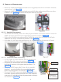
8.14.1 Removing the Door bell switch:
• Execute the steps in “8.2.1.1 Power Off:”.
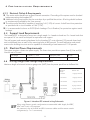
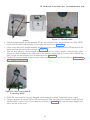
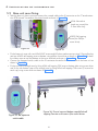
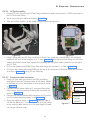
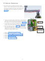
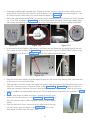
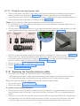
• Pull out the Dummy Logo assembly from the slot on the Door bell switch assembly and remove the
front cover by removing 4 M3×6 HSHC Screws using 2.5mm Allen key. Keep the removed parts aside.
• Disconnect the communication cable coming from the base unit from the Console extension board-External. Remove the Console extension board-External from the wall plate by removing 4 M3×6 HSHC
screws using 2.5mm Allen key.
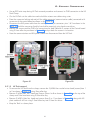
8.14.2 Replacing the Door bell switch:
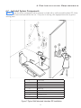
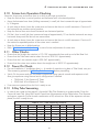
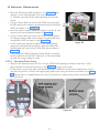
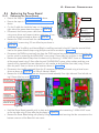
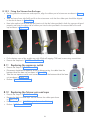
• Take the new Door bell switch assembly from the packing box and pull out the Dummy Logo assembly from the slot on the Door bell switch assembly and remove the front cover by removing 4 M3×6
HSHC screws using 2.5mm Allen key.
• Keep the removed parts aside carefully. Remove the Console extension board-External from the wall
plate by removing 4 M3×6 HSHC screws at the four corners using 2.5mm allen key.
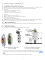
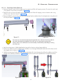
• If required remove the old wall plate from wall 2 M6×30 lag bolts using 8mm box spanner and fix the
new wall plate on the wall with 2 M6×30 lag bolts using 8mm box spanner.
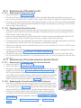
• Take the new Console extension board-External and fix it to the wall plate with 4 M3×6 HSHC screws
using 2.5mm Allen key.
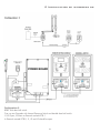
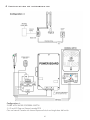
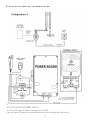
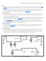
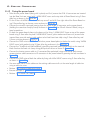
• Connect the communication cable to the appropriate connector by referring the configuration connection diagrams in Section “5.8 Intraskan DC Console configurations:”.
• Take the new front cover and fix it on the wall plate with 4 M3×6 HSHC screws using 2.5mm Allen
key. Fix the Dummy Logo assembly in the slot and switch on the unit and give exposures from the external switch.
8.15 Replacement of Console extension board-internal
8.15.1 Removing the Console extension board-internal
• Execute the steps in “8.2.1.1 Power Off:”.
• Execute the steps in “8.2.1.3 Base Unit Cover removal:”.
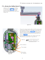
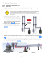
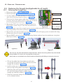
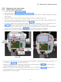
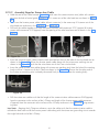
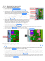
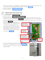
• Disconnect the external communication cable coming from the wall from the
respective connector (Refer“5.8 Intraskan DC Console configurations:”) on
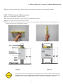
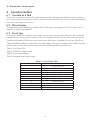
the Console extension board-internal and disconnect the cable from connector PB/J4 of the Console extension board-internal. Remove the Console
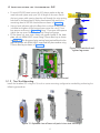
extension board-internal from the base unit plate by removing 4 M3×6
HSHC screws at the locations shown in Figure 118 using 2.5mm allen key.
8.15.2 Replacing the Console extension board-internal:
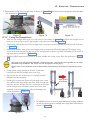
• Take the new Console extension board-internal from the packing box and
fix it in the base unit with 4 M3×6 HSHC screws using 2.5mm allen key at
the locations shown in Figure 118 . Connect the cable coming from power
board to the PB/J4 connector on the Console extension board-internal.
• Connect the communication cable coming from wall to the appropriate
connector on the Console extension board-Internal board by referring the
configuration connection diagrams in Section “5.8 Intraskan DC Console
configurations:”.
• Execute the steps in "5.9 Base unit cover fixing:" and "5.12 Power On
Check:".
60
Figure 118