1
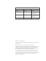
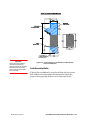
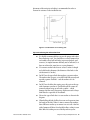
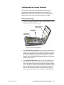
Arca2600
Teller-Assist Currency Dispenser
Site Preparation &
Installation Guide
Document History
Document Number
Date
Remarks
700-305-3170
April 1, 2003
Initial Draft
700-305-3070/3170
July 15, 2003
Rev 1.01 Combined Site Prep
and Installation Guides into a
single document
700-305-3170
April 25, 2005
Rev. 1.20 Updated to reflect
production of new safe
enclosure
Copyright 2005 by ArcaTech Systems.
The following are trademarks of ArcaTech Systems: ArcaCash; ArcaCoin; ArcaRecycler; Arca2000;
Arca2600; Arca8000.
Other brand and product names are trademarks of their respective companies.
It is the policy of ArcaTech Systems to improve products as new technology, components, software
and firmware become available. ArcaTech Systems, therefore, reserves the right to change
specifications without prior notice. When using this document for system implementation, please
contact an authorized sales or service representative for any applicable changes.
In no event shall ArcaTech Systems or any of its suppliers be liable for any special, indirect, or
consequential damages of any nature resulting from the use of information in this document.
No part of this document may be reproduced, stored in a retrieval system or transmitted in any form
or by any means (electronic, photocopying, recording or otherwise) without prior written
permission from ArcaTech Systems.
Contents
Purpose of This Manual . . . . . . . . . . . . . . . . . . . . . . . . . . . . . . . . v
Related Documents . . . . . . . . . . . . . . . . . . . . . . . . . . . . . . . . . . . . v
Tools and Materials Required . . . . . . . . . . . . . . . . . . . . . . . . . . .vi
1 | Introduction . . . . . . . . . . . . . . . . . . . . . . . . . . . . . . . . . . . . . . . . 7
Arca2500 Users . . . . . . . . . . . . . . . . . . . . . . . . . . . . . . . . . . . . . . . . 7
Overview . . . . . . . . . . . . . . . . . . . . . . . . . . . . . . . . . . . . . . . . . . . . . . 7
Customer Responsibilities . . . . . . . . . . . . . . . . . . . . . . . . . . . . . . 8
Product Identification . . . . . . . . . . . . . . . . . . . . . . . . . . . . . . . . . . 9
2 | Physical Requirements . . . . . . . . . . . . . . . . . . . . . . . . . . . . . 11
Choosing a Dispenser Location . . . . . . . . . . . . . . . . . . . . . . . 11
Convenience for Operators. . . . . . . . . . . . . . . . . . . . . . . . . . . . 11
Product Dimensions . . . . . . . . . . . . . . . . . . . . . . . . . . . . . . . . . . 12
Product Weight and Floor Loading . . . . . . . . . . . . . . . . . . . . 12
Service Clearances . . . . . . . . . . . . . . . . . . . . . . . . . . . . . . . . . . . . 12
Safe Security Bolts. . . . . . . . . . . . . . . . . . . . . . . . . . . . . . . . . . . . . 14
Tips on Anchoring the Safe to the Floor . . . . . . . . . . 15
Floor Covering . . . . . . . . . . . . . . . . . . . . . . . . . . . . . . . . . . . . . . . . 16
Environmental Requirements . . . . . . . . . . . . . . . . . . . . . . . . . 16
Temperature and Humidity . . . . . . . . . . . . . . . . . . . . . . . . . 16
Acoustical Noise . . . . . . . . . . . . . . . . . . . . . . . . . . . . . . . . . . . 17
3 | Electrical and Cabling Requirements . . . . . . . . . . . . . . . . 19
Power Quality, Distribution and
Grounding Requirements . . . . . . . . . . . . . . . . . . . . . . . . . . . . . 19
AC Power Requirements . . . . . . . . . . . . . . . . . . . . . . . . . . . . 19
AC Power Quality . . . . . . . . . . . . . . . . . . . . . . . . . . . . . . . . . . 20
Dedicated AC Power System . . . . . . . . . . . . . . . . . . . . . . . . 20
Transient Power Loss . . . . . . . . . . . . . . . . . . . . . . . . . . . . . . . 21
External Cables. . . . . . . . . . . . . . . . . . . . . . . . . . . . . . . . . . . . . . . . 22
RS-232 Cables . . . . . . . . . . . . . . . . . . . . . . . . . . . . . . . . . . . . . . 22
4 | Unpacking the Arca2600 . . . . . . . . . . . . . . . . . . . . . . . . . . . 23
How To Unpack The Arca2600. . . . . . . . . . . . . . . . . . . . . . . . . 23
Removing the Safe Packaging . . . . . . . . . . . . . . . . . . . . 23
5 | Installing the Arca2600 . . . . . . . . . . . . . . . . . . . . . . . . . . . . . 25
Introduction . . . . . . . . . . . . . . . . . . . . . . . . . . . . . . . . . . . . . . . . . . 25
Document No. 700-305-7000
Contents iii
Installing the Safe . . . . . . . . . . . . . . . . . . . . . . . . . . . . . . . . 25
Connecting the Arca2600 Dispenser to its Peripherals. 26
Connecting Peripheral Devices . . . . . . . . . . . . . . . . . . 27
Configuring the Currency Cassettes. . . . . . . . . . . . . . . . . . . 28
Setting Currency Length . . . . . . . . . . . . . . . . . . . . . . . . . 28
Setting Cassette Types . . . . . . . . . . . . . . . . . . . . . . . . . . . 29
Adjusting Low Note Sensor Settings . . . . . . . . . . . . . 30
Appendix A: Arca2600 Parts Guide . . . . . . . . . . . . . . . . . . . . 31
Teller Terminal Cables . . . . . . . . . . . . . . . . . . . . . . . . . . . . . . . . . 31
Coin Dispenser Cables . . . . . . . . . . . . . . . . . . . . . . . . . . . . . . . . 31
Replacement Parts . . . . . . . . . . . . . . . . . . . . . . . . . . . . . . . . . . . . 31
Appendix B: Power Protection . . . . . . . . . . . . . . . . . . . . . . . . . 33
AC Power Line Transient Protection . . . . . . . . . . . . . . . . . . . 33
Data Line Transient Protection . . . . . . . . . . . . . . . . . . . . . . . . 34
Appendix C: Coin Dispenser
Cable Configurations . . . . . . . . . . . . . . . . . . . . . . . . . . . . . . . . . . 35
iv ArcaTech Systems
Arca2600 Currency Dispenser
Purpose of This Manual
This manual is intended for service personnel who are required to
prepare the site and install an Arca2600 Teller-Assist Currency
Dispenser.
IMPORTANT: The documentation for the Arca2600 dispener
model also services the Arca2500 Teller-Assist Dispenser.
This manual focuses on two procedures:
z
Pre-installation Site Preparation for the Arca2600
z
Installation of the Arca2600
Related Documents
For more detailed information on the Arca2600, you may consult the
following documents that are available in addition to this Site
Preparation & Installation Manual:
z
Arca2600 User Guide (Document No. 700-305-2526)
z
Compass Setup Guide (Document No. 700-305-1053)
z
Dispenser Software User Guide (varies depending on software
interface).
To order any of this related documentation, contact ArcaTech Systems.
In the Americas:
ArcaTech Systems LLC
437 Dimmocks Mill Road
Hillsborough, NC 27278 USA
Phone: +1 919 245 1891
Fax: + 1 919 882 9998
In Europe:
ArcaTech Systems Europe Ltd
Conference House152 Morrison Street
Edinburgh EH3 8EB
Phone: +44 870 351 8384
Fax: +44 870 351 8385
Email:
Information: [email protected]
Sales: [email protected]
Support: [email protected]
Document No. 700-305-3170
Tools and Materials Required
ArcaTech Systems
z
Equipment for moving very heavy objects (safe)
z
Phillips-head screwdriver, Metric True#2
z
Wire cutters
z
Long-Handled Socket Wrench
z
Rotary Drill & Anchor Bolts (if floor anchors are to be used)
z
See Site Preparation Survey for specific non-standard
requirements
Arca2600 Site Prep & Installation Guide Rev. 1.20
1
Introduction
Arca2500 Users
The Arca2600 and Arca2500 models are almost identical, therefore this
Arca2600 Guide also services the Arca2500 dispenser model with
differences noted as appropriate. The Arca2500 model has five currency
cassettes and the Arca2600 has six currency cassettes. Other than a few
slight differences (e.g. number of cassettes, dispenser control board,
etc.), these models are virtually identical.
Overview
The Arca2600 Teller Assist Currency Dispenser has been designed for
ease of use by one, two or three operators. Paper currency (notes) are
delivered as a bundle through an exit shutter called the note delivery
area. When notes are delivered to the note delivery area, the green
operator light corresponding to the terminal (operator) that dispensed
the currency will light up. Subsequent dispenses will not be allowed as
long as notes remain in the note delivery area. Once the currency is
removed by the operator, the Arca2600 becomes free for the next
operation.
The Arca2600 is available in two note delivery configurations: a Front
Access model with the note delivery area and operator lights on the front
of unit and a Rear Access model that features the note delivery area and
operator lights on the rear of the unit.
The Arca2600 features an appearance door with a keyed lock. The
appearance door is an added asthetic and safety feature making the unit
appear less like a safe. The appearance door opens to reveal the safe door
with a lock and handle for accessing the safe unit.
Document No. 700-305-3170
Chapter 1: Introduction 7
Figure 1-1 shows the key components of a Front Access Arca2600
Dispenser.
Left Operator
Light
Right
Operator Light
Note Delivery
Area
Appearance
Door
Keyed Appearance
Door Lock
Figure 1-1: Arca2600 Safe Unit (Front Access Model)
Customer Responsibilities
When required by ArcaTech Systems, the customer must provide
designated customer service representatives with access to appropriate
drawings that indicate:
8 ArcaTech Systems
z
Planned location of the equipment
z
Site wiring (power and signal, paths and lengths)
z
Location of other equipment capable of generating electrical
noise, electromagnetic interference, heat, etc.
Arca2600 Site Prep & Installation Guide Rev. 1.20
To ensure the environmental requirements of the system are met, the
customer must perform the following if necessary:
Important:
You will need to provide the
serial number when calling for
maintenance or service.
Document No. 700-305-3170
z
Make building alterations necessary to meet wiring and other
site requirements.
z
Provide and install all communications cables, wall jacks,
special connectors, and associated hardware.
z
Provide and install necessary power distribution boxes,
conduits, grounds, lighting protection, and associated
hardware.
z
Make sure all applicable codes, regulations and laws
(including, but not limited to, electrical, building, safety, and
health) are met.
z
Provide and install auxiliary power or other equipment as
required.
z
Provide storage or service areas as required.
z
Provide floor coverings and environmental systems that limit
or control static electricity build-up and discharge.
Product Identification
The product identification label can be found on the inside of the safe
door. The product is identified by its model, part and serial numbers.
PLEASE DO NOT REMOVE THIS LABEL FROM THE Arca2600.
Chapter 1: Introduction 9
10 ArcaTech Systems
Arca2600 Site Prep & Installation Guide Rev. 1.20
2
Physical Requirements
Choosing a Dispenser Location
Prior to receiving the Arca2600 you should select a location in which it
is to be installed. There are several criteria to consider when choosing a
location:
z
Convenience for operators
z
Product dimensions
z
Product weight and floor loading
z
Installation clearances
z
Service clearances
z
Security bolts and washers (optional)
z
Environmental requirements
z
Electrical requirements
The electrical requirements for the Arca2600 are described in Chapter 3:
Electrical and Cabling Requirements.
Convenience for Operators
Efficiency and convenience for operators should be the primary criteria
for selecting a suitable location for the Arca2600. If the Arca2600 is to be
used by two operators, it should ideally be placed between the two
operators so that each have easy access to the note delivery area.
Alternatively, if the Arca2600 is to be used by more than two operators
(for instance, as a vault dispenser), then it may be placed behind the
counter in an area accessible by all operators.
Document No. 700-305-3170
Chapter 2: Physical Requirements 11
Product Dimensions
Table 2.A lists the dimensions of the ArcaCash dispenser models
2500 and 2600.
Table 2.A: Exterior Safe Dimensions of Arca2600
Width of Safe
18 in (457 mm)
Height of Safe
38.5 in (978 mm)
Depth of Safe
29.5 in (749 mm)
Total Depth of
32 in (813 mm)
Safe with
Appearance Door
Product Weight and Floor Loading
The maximum weights and floor loading values of the Arca2600 are
illustrated in Table 2.B:
Table 2.B: Product Weight and Floor Loading
Weight*
Loading
Arca2500
1155 lb (524 kg)
2.18 lb/in2 (0.15 kg/cm2)
Arca2600
1167 lb (529 kg)
2.20 lb/in2 (0.15 kg/cm2)
*Weight indicates maximum weight of the safe enclosure and dispenser with all cassettes
loaded and filled to capacity with currency.
Service Clearances
Adequate service clearances should be provided to allow service
personnel to connect and disconnect the Power and Communication
cables for the Arca2600, as well as to allow the safe door to swing
through 180° to allow the dispenser mechanism to rack out for
servicing. Refer to Table 2.C and Figure 2-1 for the appropriate service
clearances:
Table 2.C: Minimum Recommended Service Clearances
12 ArcaTech Systems
Minimum
Clearance
Front Access Model
Rear Access Model
Rear
6 in (150 mm)
18 in (457 mm)
Right
16 in (406 mm)
14 in (356 mm)
Front
30 in (750 mm)
30 in (750 mm)
Left
6 in (150 mm)
6 in (150 mm)
Arca2600 Site Prep & Installation Guide Rev. 1.20
Figure 2-1: Service Clearances for Front Access Model (units
shown in millimeters)
Document No. 700-305-3170
Chapter 2: Physical Requirements 13
Important:
Carpet, flooring variances,
cabinet placement and
uneven surfaces can all affect
the placement of security
bolts for the secure installation of the safe
14 ArcaTech Systems
Figure 2-2: Service Clearances for Rear Access Model (units
shown in millimeter)
Safe Security Bolts
If desired, the Arca2600 can be secured to the floor with safe security
bolts. Holes have been provided in the bottom of the safe for this
purpose. When preparing the floor to receive the security bolts,
Arca2600 Site Prep & Installation Guide Rev. 1.20
placement of the unit prior to bolting is recommended in order to
account for variances at the installation site.
Figure 2-3: Bolt Patterns for mounting safe
Tips on Anchoring the Safe to the Floor
Document No. 700-305-3170
X
It is highly recommended that you use the proper tools when
floor mounting a safe. You should have a rotary hammer that
can handle at least half-inch holes in pressure-packed, aged
concrete. (A simpler hammer drill may not be sufficient, as it
does not achieve the same force as a rotary hammer).
X
Use concrete anchor bolts that are at least 3 inches in length
and a half-inch in diameter (the diameter of the holes in the
safe bottom is 0.5 inches).
X
Do NOT use the type of bolt that employs a separate anchor.
The anchor takes up space, so in a half-inch hole you only end
up with a quarter-inch bolt -- and the anchors can’t be
removed.
X
Do NOT use the bolts that require you to hit a pin on the top
with a hammer to anchor it. It will hold well, but cannot be
removed without being cut off with a grinder -- which
damages the floor and is dangerous, unpleasant work. Always
think ahead to a possible de-installation.
X
DO use the type of bolt that is its own anchor as shown in the
diagram.
X
When drilling the hole, drill it at least one-and-a-quarter times
the length of the bolt. When it's time to remove the machine,
there will be no need to try to remove it or cut it off. A few hits
with a hammer will drive it level with the floor, sealing its own
hole. Bolts left sticking out are a liability and an eyesore.
Chapter 2: Physical Requirements 15
X
Remove (vacuum) all of the drilling dust out of the hole. Dust
packed in by an incoming bolt will prevent it from going all the
way in.
X
Use large washers and tighten the nuts well by hand. The
tightening of the nut is what locks the anchor in as it moves up.
A loose connection also gives a machine a chance to build
momentum if someone tries to tear it out.
X
Remove all dust and swarf from the area around the bolt holes
before securing the safe to the building floor.
Figure 2-4: Proper Bolts for Floor Mounting
Floor Covering
An antistatic floor covering should be used and must be of a type that
will not generate dust or fluff.
Environmental Requirements
For the Arca2600 Currency Dispenser to function correctly, the
installation site should meet the following environmental requirements.
Temperature and Humidity
The Arca2600 can be operated in a wide range of environmental
conditions. It is recommended, however, that the unit not be operated
continuously at the limits of its temperature and humidity tolerance.
Environmental requirements for the Arca2600 are listed in Table 2.D.
CAUTION! DO NOT operate the dispenser in moist conditions that
could cause condensation.
16 ArcaTech Systems
Arca2600 Site Prep & Installation Guide Rev. 1.20
Table 2.D: Environmental Requirements
Working
Stop State
Temperature
Range
0° C to 32° C
32° F to 90° F
-5° C to 50° C
23° F to 122° F
Humidity Range
10 to 85%
8 to 95%
Acoustical Noise
The Noise Power Emission Level (L NPE) does not exceed the following
maximums for Level 1 environments:
Document No. 700-305-3170
X
Operating: < 72 decibels
X
Idle: < 65 decibels
Chapter 2: Physical Requirements 17
18 ArcaTech Systems
Arca2600 Site Prep & Installation Guide Rev. 1.20
3
Electrical and Cabling
Requirements
This section contains the electrical requirements which must be
considered when preparing for the installation of an Arca2600. Also
contained in this chapter are details of the external cables which may be
connected to the Arca26000.
Power Quality, Distribution and Grounding
Requirements
Voltage transients, line noise, surges, sags, impulses, and spikes may be
experienced routinely or sporadically. When such phenomena occur,
the use of protective devices, as described in Appendix B, may be
required to ensure proper operation of the equipment.
AC Power Requirements
The branch circuit that provides the AC power to the Arca2600 must
meet the minimum requirements according to the power data chart in
Table 3.A. The circuit should have three conductors (live, neutral,
insulated and isolated ground) and be protected by an appropriate
circuit breaker. The branch circuit must be installed in accordance with
country, state and local codes.
Table 3.A: AC Power Requirements
Voltage
110 V
240 V
Frequency
50 – 60 Hz
50 – 60 Hz
Current/Amperes
30 A
15 A
It is recommended that the branch circuit be connected to the same load
center that provides the AC power for the host software system to which
the Arca2600 and coin dispenser are connected.
Document No. 700-305-3170
Chapter 3: Electrical and Cabling Requirements 19
AC Power Quality
The required AC power distribution system is a dedicated power
distribution system that uses insulated/isolated ground lines.
ArcaTech Systems strongly recommends that any device that
connects to the shielded communication line of a higher level device
has the same quality AC power as the higher level device. If this
recommendation is not met, AC power problems on power source
for the lower level device source could nullify the quality of the entire
local communications network.
IMPORTANT: Performance cannot be guaranteed if the electrical
requirements listed in this guide are not met.
Dedicated AC Power System
This system is defined as the feeder from the building load center; all
conducted conduits, channels, junction boxes, panels and sub-panels;
and all receptacles connected to these panels or sub-panels. Only
ArcaTech Systems devices and devices sanctioned by ArcaTech Systems
should be connected to this system. The system must contain an
insulated/isolated ground line that is only tied to the neutral at the load
center.
An example of a dedicated AC power system is shown in Figure 3-1 and
Figure 3-2. These figures are only examples and are not intended to
supersede local electrical codes.
Figure 3-1: Dedicated AC Power System (Example 1)
20 ArcaTech Systems
Arca2600 Site Prep & Installation Guide
Figure 3-2: Dedicated AC Power System (Example 2)
Transient Power Loss
The voltage loss due to power interruptions must not be more than 50%
of the nominal value for a maximum of one half cycle at a maximum rate
of 1 every 10 seconds.
Document No. 700-305-3170
Chapter 3: Electrical and Cabling Requirements 21
External Cables
RS-232 Cables
RS-232 cables can be used for connecting the Arca2600 to an RS-232
port on a parent host unit. These cables are not shipped with the unit. A
schematic diagram is shown in Figure 3-3.
To connect an Arca2600 dispenser to a 9-pin RJ45 serial port on teller
terminal (host unit) use the following cable: 15’ RS-232 RJ45 to 9-pin
female (this cable corresponds to ArcaTech Part No. 150-401-3001)
DISPENSER
(RJ45 Connector)
Host Unit
(9-pin Female)
Need new pinout - See Steve
RTS
CTS
GND
RXD
TXD
5
4
3
2
1
4
6
1
8
7
5
3
2
DTR
DSR
DCD
CTS
RTS
GND
TXD
RXD
Figure 3-3: RS-232 Cable to Port Connection Diagram
In addition to these dispenser cables, you may also need a cable to
connect the Arca2600 to a coin dispenser. In most cases, coin dispensers
come equipped with a fixed cable that can be plugged directly into one
of the 9-pin RJ45 ports on the Arca2600. However, if a cable is required
to connect to the coin dispenser see Appendix A for a list of cables and
their part numbers and Appendix C for the cable configurations.
22 ArcaTech Systems
Arca2600 Site Prep & Installation Guide
4
Unpacking the Arca2600
How To Unpack The Arca2600
The dispenser mechanism for the Arca2600 is integrated with the safe
enclosure. Prior to installing Arca2600 you should remove all of the
shipping packaging from the safe as described in this chapter. To reduce
the chance of damaging the finish of the safe, it is recommended that the
Arca2600 be moved as close as possible to its installation position prior
to removing the packaging.
CAUTION! The Arca2600 weighs approximately 1100 lbs (500 kg). It is
recommended that professionals unpack and move the
Arca2600.
Removing the Safe Packaging
1. Check the packaging of the safe. If the safe has been obviously
damaged or appears to have tipped during transit, contact your
ArcaTech Systems representative immediately.
2. Remove the protective wrapping from the safe.
3. Open the safe door. If it is locked, the default combination is 50. Turn
counter-clockwise 3 full rotations and stop on 50; then turn
clockwise until you feel lock open, usually at about 90. If your safe is
equipped with an electronic lock, the normal single user default
combination is 1-2-3-4-5-6 # and should be labeled on the lock.
4. Remove the bolts that secure the safe to the shipping pallet with a
long handled socket wrench.
5. Remove the protective packaging from around the dispenser. Using
a metric Phillips Metric True #2 screw driver, remove the yellow
cassette shipping braces. These can be stored using the same
mounting holes, by attaching the brackets to the outside of the pick
module instead of the inside.
Document No. 700-305-3170
Chapter 4: Unpacking the Arca2600 23
6. Pull and remove the locking pin from the left side of the dispenser.
Pull the dispenser out until the slides on which it is mounted are fully
extended.
7. Inspect the unit for any internal shipping damage, such as broken or
disconnected cables, loose or misaligned pick modules or other
apparent problems.
8. If the unit appears to be in good condition, push the dispenser back
into the safe and secure it with the locking pin.
9. Carefully remove the safe from the skid. Professional safe moving
equipment should be used for this operation.
CAUTION! To prevent the Arca2600 from tipping over, great care
should be taken when removing it from the skid.
10. You are now ready to position the safe in its chosen installation
location (refer to Chapter 2: Physical Requirements for more
information on choosing a suitable location).
24 ArcaTech Systems
Arca2600 Site Prep & Installation Guide Rev. 1.20
5
Installing the Arca2600
Introduction
The steps required for installing the Arca2600 are:
X
Installing the Safe
X
Connecting the Arca2600 to the host terminal/PC
X
Connecting the Arca2600 to the coin dispenser (optional)
X
Configuring the Currency Cassettes
X
Confirming Communications Settings and Dispenser Options
using Firmware Utility
Installing the Safe
Important:
Depending on the installation
location and access, it may be
necessary to connect the
power and communication
cables before moving the
Arca2600 to its operating location.
1. Position the safe in its final location. The safe should be positioned
such that the note delivery area is within easy reach of the
operator(s).
2. Position the safe to allow enough space for proper access to the cable
connectors. Refer to Site Prep Specifications for more details.
3. Ensure the safe is level (the sides of the safe should be completely
perpendicular to its top and floor).
4. If you are going to bolt the safe to the floor, do so now. It may be
necessary to remove the dispenser mechanism from the mounting
rails and disconnect all cables from the mechanism. Refer to Tips on
Anchoring the Safe to the Floor in Chapter 2: Physical Requirements
the recommendations on floor mounting.
Document No. 700-305-3170
Chapter 5: Installing the Arca2600 25
Connecting the Arca2600 Dispenser to its
Peripherals
You can connect the Arca2600 to one, two or three host terminals. The
type of cable you use is determined by the connections available at the
host terminal and the host software you are using. See Appendix A:
Arca2600 Parts Guide for the communication cable types available from
ArcaTech Systems.
The steps below outline the procedures for connecting the Arca2600 to
its host terminals and optional coin dispenser(s).
IMPORTANT: Host terminals for operating the Arca2600 are not
provided with the Arca2600 dispenser. The Arca2600 will communicate with any host software that uses the NCR 5175 or Inter Innovation (DeLaRue/LeFebure) protocols. If you need
recommendations as to which type of host connectivity solution
may be most appropriate for your installation, contact ArcaTech
Systems or one of its authorized dealers.
Figure 5-1: Cable Connections to Arca2600 Dispenser
26 ArcaTech Systems
Arca2600 Site Prep & Installation Guide Rev. 1.20
Connecting Peripheral Devices
1. Connect the Host Terminals and optional Coin Dispenser(s) as
required for your configuration; the cable connector is located on the
right rear side of the safe.
Communications (cable
connection) Panel
Figure 5-2: Location of the cable connection panel.
Document No. 700-305-3170
Chapter 5: Installing the Arca2600 27
Configuring the Currency Cassettes
The currency cassettes have adjustable guides that allow you to
configure them to dispense many different sizes of media. For a
complete description of the cassettes and the sizes of media they can
dispense, please refer to the Service Manual for the Arca2600.
Setting Currency Length
1. There are two types of bill guides in the cassette which line up with
markings on the insides of the cassette.
Magnet bracket for
cassette typing
Adjustable bill
width guide
Adjustable bill
length guide
Figure 5-3: Currency Size Guides
2. The Adjustable Bill Length Guides (silver color) are found on each
side of the cassette and have a vertical brace to keep the notes from
shifting out of alignment. The vertical tabs of the guides should line
up at the “156” marks at the front and rear of the cassette for US
currency. They can be adjusted by loosening the four set screws that
hold the guides in place.
3. The Adjustable Width Guides (gray color) are also found on each
side of the interior of the cassette. These horizontal guides keep the
notes at the right level for proper operation of the dispenser picking
system. The tabs on either end of the width guide should be inserted
into the fourth opening at the front and rear of the cassette for US
currency. The sides of these guides are fastened to the side of the
cassette by two slotted set screws on each side. The tops of the side
28 ArcaTech Systems
Arca2600 Site Prep & Installation Guide Rev. 1.20
brackets should line up with the fourth hash mark under the “60”
mark for US currency. For the settings for non-US currency, please
refer to the Service Manual or contact ArcaTech Systems.
Bill width guide
hashmarks
Set screws for
bill width guides
Bill length guide
hash marks
Set screws for
bill length
Figure 5-4: Bill width and bill length guides and setting marks
Setting Cassette Types
1. Each Arca2600 dispenser cassette can be configured as Type 1
through 14. For US currency, types 1 through 6are typically used.
Each different denomination must use a unique cassette type. The
cassette types are configured using magnets located in a panel
attached inside the top of the cassette by two thumb screws. Figure
5-5 illustrates how the magnets should be placed. The magnet
placement chart can also be found on the outside lid of the cassette.
CASSETTE
TYPE
US
Denomination
MAGNET CONFIGURATION
= Magnet Present
D
1
$1
2
$5
3
$10
4
$20
5
$50
6
$100
C
B
A
Figure 5-5: Cassette types, denomination and magnet placement in dispenser cassettes placement.
Document No. 700-305-3170
Chapter 5: Installing the Arca2600 29
2. Open the cassette lid. Loosen the two thumb screws and remove the
magnet bracket from the lid of the cassette.
Cassette type
magnet
Unused magnet
place holders
Figure 5-6: Cassette type magnet bracket (removed from
cassette lid)
Notice that there are three magnets in the bracket. Place the magnets on
the pins in the proper positions for the specific type you are configuring.
The far left two pins are designed to hold extra magnets that are not
needed.
Adjusting Low Note Sensor Settings
1. A sensor on the outside of each pick module measures the relative
position of the pressure plate inside the cassette to the position of the
sensor. Changing the position of the sensor determines at what point
the “low note” status is flagged.
Bracket placement
guide
Bracket placement
mounting holes
Low note sensor
bracket
Mounting screws
for bracket
Figure 5-7: Currency Low Note Status Sensor
Note: The low note sensor
level has a default
setting of 100 notes.
2. The low note sensor can be set to be triggered at approximately 50,
100, 150, 200, 250 or 300 notes. When the magnet inside the cassette
passes the reed switch in the low note sensor, a message is sent from
the Arca2600 to the host terminal that the level of notes is low inside
the cassette.
3. To adjust the setting, remove the mounting screws and position the
bracket to the desired setting as shown on the diagram.
30 ArcaTech Systems
Arca2600 Site Prep & Installation Guide Rev. 1.20
Arca2600 Parts Guide
Appendix A
Teller Terminal Cables
Part Number
Description
150-401-3001
15’ DB9 Female to RJ45 - For use with host terminal with a 9-Pin
Male Serial Port communicating in DeLaRue/LeFebure emulation
mode.
150-401-4522
15’ DB25 Female to RJ45 - For use with host terminal with a 25-Pin
Male Serial Port communicating in DeLaRue/LeFebure emulation
mode.
150-401-9856
5’ DB25 Female to RJ45 - For use with MiniTerminal host
controller.
Coin Dispenser Cables
Part Number
Coin
Dispenser Type
150-205-6012
Telequip Transact-1
10’ non-standard RS-232 9-pin male to 9-pin
female
150-825-2028
OrangeCoin
10’ non-standard RS-232 9-pin male to 9-pin
female
150-205-6014
Telequip Transact 2+ 10’ non-standard RS-232 9-pin male to 9-pin
female
150-205-9815
CM-1
Description
10’ non-standard RS-232 9-pin male to 9-pin
female
Replacement Parts
Part Number
Description
580-000-9270
Currency Cassette (Standard)
580-000-9299
Currency Cassette Locks
call
Workstation Communication Cables
401-291-0051
Touch Up Paint (Frost Gray)
call
Key for safe lock
call
Key for changing lock combination
800-580-5011
Compass Configuration Software
31
32 ArcaTech Systems
Arca2600Site Prep & Installation Guide
Appendix B
Power Protection
AC Power Line Transient Protection
In the process of power distribution, transient electrical energy
(including but not limited to, lightning strikes, intermittent short
circuits, and switching transients) can be introduced onto power lines.
Such transient energy can be very damaging to electronic hardware and
can cause data corruption. Under these circumstances, ArcaTech
Systems recommends the use of AC power transient suppressors and
data (communication) line transient suppressors. Such protective
devices are intended to guard against power and data transients that can
result in hardware damage and various system or program errors.
Improvement of any deficiencies in power quality is a customer
responsibility. Malfunction and/or component failure as a result of
power quality problems are/is not covered by ArcaTech Systems'
warranty. ArcaTech Systems accepts no liability for any such occurrence
nor for its consequences.
When power transient suppression is required, the suppressors used
should meet the following minimum requirements:
X
Dissipate energy to match the appropriate application categories as
defined by IEEE Standard 587. These categories are described in
Table B.1.
Table B.1: Transient Categories
Location Category
A=Outlets > 10m (30 ft) II
from Cat. B
A= Outlets > 20m (60 ft)
from Cat. C
B=Major feeders, short III
branch circuits, and
load centers
C = Service Entrance
and run to load center
IV
0.5 µs Risetime, then 100 kHz 6 kV
Ringwave, each
200A
peak=60% of previous
Volts=1.3 x 5 µs
Current= 8 x 20 µs
and 0.5 µs Rise = 100 kHz
Ring- waved
Volts = 1.2 x 5 µs
Current = 8 x 20 µs
6kV
3kA
6kV
500A
10kV or more
10kA or more
33
X
Be voltage limiting (clipping) or tracking filter type. The suppressor
must not ‘clamp’ the voltage to zero, and must self-recover after the
passage of the transient. The suppressor may be hybrid-type
construction that makes use of various technologies in order to meet
speed and dissipation requirements.
X
Exhibit a ‘short circuit’ mode upon its failure, thus providing a
positive indication of its failure such as a blown fuse or tripped
breaker.
X
Be listed by the accepted safety organization for the country
involved (e.g., UL, CSA, VDE, ETL, etc.) and the installation must
conform to local, state, and national electrical codes and regulations.
Data Line Transient Protection
The nature of the transient phenomenon may extend to data
communication lines connected to this equipment. It is the
responsibility of the customer to install and connect a data line transient
suppression system to correct or prevent any deficiencies. Such systems
must meet the following minimum requirements:
34 ArcaTech Systems
X
Be voltage limiting and must self-recover after passage of the
transient.
X
Exhibit a ‘short circuit’ mode upon its failure to insure a positive
indication of its failure.
X
Insert less than 5 ohms resistance and minimal inductive and
capacitive loading at the operating frequency, in each data line in
order to avoid signal degradation.
X
Be installed in accordance with all applicable local, state, and
national electrical codes and regulations.
Arca2600Site Prep & Installation Guide
Appendix C
Coin Dispenser
Cable Configurations
Telequip Transact 2+ to PC Serial Port
Telequip
RJ45 Male
RXD
TXD
GND
5
6
7
Green
Yellow
Brown
PC
DB9 Female
2
3
5
TXD
RXD
GND
AC2600
RJ45 Male
2
1
3
TXD
RXD
GND
PC
DB9 Female
3
2
5
RXD
TXD
GND
AC2600
RJ45 Male
1
2
3
RXD
TXD
GND
AC2600
RJ45 Male
2
1
3
TXD
RXD
GND
PC
DB9 Female
2
3
5
TXD
RXD
GND
Telequip Transact 2+ to AC2600
Telequip
RJ45 Male
RXD
TXD
GND
5
6
7
Green
Yellow
Brown
Telequip Transact 1 to PC Serial Port
Telequip
DB9 Female
TXD
RXD
GND
2
3
5
Telequip Transact 1 to AC2600
Telequip
DB9 Female
TXD
RXD
GND
2
3
5
CM-1 to AC2600
CM-1
DB9 Male
RXD
TXD
GND
2
3
5
CM-1 to PC Serial Port
Cm-1
DB9 Male
RXD
TXD
GND
2
3
5
35
36 ArcaTech Systems
Arca2600Site Prep & Installation Guide