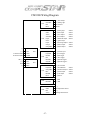
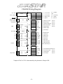
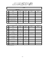
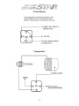
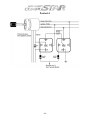
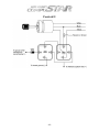
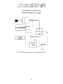
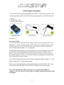
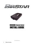
1
By:
Master Install Guide
CM3 Series - CM4200 – CM1000A
FOR DISTRIBUTION TO AUTHORIZED
COMPUSTAR DEALERS ONLY
04/27/06
-1-
-2-
TABLE OF CONTENTS
Install Checklist ..................................................................................Page 4
Remote Programming Procedure
1WAM4R, 1WFM4R, 1W900FM4R, 1WSSR ......................Page 7
1WSS4R w/ 2WSSR...............................................................Page 7
1WFM6R ................................................................................Page 8
2WFMR-S, 2WAMR, 2WFMR, 2W900FMR .......................Page 8
2WSSR....................................................................................Page 8
Common Procedures
Antenna Mounting ................................................................Page 13
Dip Switch and Jumper Settings ...........................................Page 13
The Little Green Loop ..........................................................Page 14
Adjusting Siren Volume .......................................................Page 14
Adjusting Shock Sensor Sensitivity......................................Page 14
Programming Tach/Alternator Sensing ................................Page 14
Diagnosing Remote-Start Problems......................................Page 15
Control Modules
CM3000 ................................................................................Page 19
CM3300 ................................................................................Page 27
CM4200 ................................................................................Page 33
CM1000A .............................................................................Page 39
Option Programming
Four Button Remotes w/ Same Lock/Unlock Button ...........Page 45
Four Button Remotes w/ Separate Lock/Unlock Buttons.....Page 45
R500A ...................................................................................Page 46
1WFM6R ..............................................................................Page 47
Two-Way Remotes ...............................................................Page 47
CM3-Series Option Programmer ..........................................Page 48
Resetting Options to Factory Defaults..................................Page 48
Option Menus........................................................................Page 51
Options Explained In Detail..................................................Page 55
Installation Assistance
FAQ / Trouble Shooting .......................................................Page 63
Common Diagrams ...............................................................Page 65
Accessory Manuals ...........................................................................Page 75
-3-
Install Checklist
Please use this checklist to complete the installation of any CompuStar system. These
steps should be done in the order shown.
Prep/Install Module:
Begin preparing the system for installation by removing any wires you are not going to
be using, leave some of the wire in case you need to use it in the future. Then wire up any
relays, etc., and install the control module in the vehicle.
Code Remote:
Code the remote using the remote coding procedure shown in this manual. The remotes
do not come preprogrammed as a result of the modular design of the CompuStar lineup.
Program Tach:
Program tach by tapping the tach learn button located on the back of the control module.
Set Options:
Using the Option Programming section of this manual, set the options of the control
module.
Test:
Test the system by testing and adjusting the shock sensor, testing the remote start process,
and verifying all of the alarm triggers.
-4-
Remote Programming Procedures
-5-
-6-
Remote Programming Procedures
Because the CompuStar systems are modular in design (upgradeable), the remotes Do
Not come pre-programmed from the factory. Listed below are the procedures for
programming the CompuStar transmitters.
Programming for:
1WAM4R (all versions), 1WFM4R (all versions), 1W900FM4R (all versions),
and for programming the 1WSS4R as a standalone remote:
1. Insert the key into the ignition and turn the ignition ON then OFF five times.
2. The fifth time you turn the ignition on, the parking lights will flash once.
3. Tap the Top Left button on the transmitter once. The parking lights will again
flash once to confirm that the remote was coded.
4. After a few seconds, the parking lights will flash twice to signal the ending of
the remote programming mode.
If you have multiple remotes, you can program them all at once by coding the first
remote, then right after getting the confirmation flash, coding the second remote
(you will get another confirmation flash), and then coding the third remote.
Programming for:
1WSS4R, when using it in conjunction with the 2WSSR.
If you plan to use the 2WSSR and the 1WSS4R together, you must program them
at the same time.
1. Pull the positive side of the battery out of the 2WSSR, do not remove the whole
battery as you will need to quickly insert it again.
2. Insert the key into the ignition and turn the ignition ON then OFF five times.
3. The fifth time you turn the ignition on, the parking lights will flash once.
4. Quickly push the positive side of the battery back into the 2WSSR. The parking
lights will flash once to confirm that the remote was coded.
5. Immediately after, tap the Top Left button on the 1WSS4R once. The parking
lights will again flash once to confirm that the remote was coded.
6. After a few seconds, the parking lights will flash twice to signal the ending of
the remote programming mode. Do not press any buttons on either remote, the
2WSSR will still be in the process of synchronizing. As soon as the 2WSSR
chirps once or twice, you are finished and can use the remotes. This should
only take a few seconds.
-7-
Programming for:
1WFM6R
1. Insert the key into the ignition and turn the ignition ON then OFF five times.
2. The fifth time you turn the ignition on, the parking lights will flash once.
3. Tap the Lock button on the transmitter once. The parking lights will again flash
once to confirm that the remote was coded.
4. After a few seconds, the parking lights will flash twice to signal the ending of
the remote programming mode.
If you have multiple remotes, you can program them all at once by coding the first
remote, then right after getting the confirmation flash, coding the second remote
(you will get another confirmation flash), and then coding the third remote.
Programming for:
2WFMR-S, 2WAMR, 2WFMR, and 2W900FMR
1. Insert the key into the ignition and turn the ignition ON then OFF five times.
2. The fifth time you turn the ignition on, the parking lights will flash once.
3. Tap the ( I ) button on the transmitter once. The parking lights will again flash
once to confirm that the remote was coded.
4. After a few seconds, the parking lights will flash twice to signal the ending of
the remote programming mode.
If you have multiple remotes, you can program them all at once by coding the first
remote, then right after getting the confirmation flash, coding the second remote
(you will get another confirmation flash), and then coding the third remote.
Programming for:
2WSSR
1. Pull the positive side of the battery out of the 2WSSR, do not remove the whole
battery as you will need to quickly insert it again.
2. Insert the key into the ignition and turn the ignition ON then OFF five times.
3. The fifth time you turn the ignition on, the parking lights will flash once.
4. Quickly push the positive side of the battery back into the 2WSSR. The parking
lights will flash once to confirm that the remote was coded.
5. After a few seconds, the parking lights will flash twice to signal the ending of
the remote programming mode. Do not press any buttons on the remote, the
2WSSR will still be in the process of synchronizing. As soon as the 2WSSR
chirps once or twice, you are finished and can use the remote. This should only
take a few seconds.
-8-
You can only use 1 two-way remote at a time with each install. However, 1 oneway remote can be added to the system.
-9-
- 10 -
Common Procedures
- 11 -
- 12 -
Antenna Mounting
CompuStar antennas can, in general, be mounted with any orientation. Horizontal or
vertical, doesn’t really matter. Things to consider would be the routing of the antenna
cable, and mounting the antenna a few inches down from the roof and/or tint line. If the
antenna cable is pinched or crimped on its way to the antenna, the system may experience
problems such as; poor range, one-way communication on two-way models, or possibly
no response at all. Metal acts as a natural shield to radio frequency signals so mounting
the antenna close to the roof, or behind some kinds of tint that have metal content to
them, can cause poor performance.
Dipswitch and Jumper Settings
Dipswitch settings for:
CM3000, CM3200, CM3300, and CM4200
1. Dipswitch #1 will select the engine-sensing mode, tach or alternator. The ON
position is for tach sensing (Note: Factory default is tach sensing.) The OFF
position is for alternator sensing.
2. Dipswitch #2 will select the remote start run time. The OFF position will
provide a 15-minute run time for gas vehicles and a 25-minute run time for
diesel vehicles. The ON position will provide a 25-minute run time for gas
vehicles and a 45-minute run time for diesel vehicles.
Jumper settings for:
CM4200
1.
Jumper #1- 2nd Ignition 12-volt (+) positive output to the blue wire on
connector 1.
2. Jumper #2- 2nd Accessory 12-volt (+) positive output to the blue wire on
connector 1.
3. Jumper #3- 2nd Starter 12-volt (+) positive output to the blue wire on
connector 1.
- 13 -
The Little Green Loop
This wire is only present in international models. This jumper wire will determine the
transmission setting. If the jumper wire is not cut the control module will be set for
manual transmission mode. (Note: The factory default is manual transmission. If the
control module is installed in a manual transmission vehicle and the jumper is cut ALL
WARRANTY is void.) When the jumper wire is cut the control module will be set for
automatic transmission mode.
Adjusting Siren Volume
To increase the volume of the siren, cut the black loop of wire located on it. This will
increase the volume of the siren by 3 dB.
Adjusting Shock Sensor Sensitivity
To adjust the sensitivity of the shock sensor, turn the dial located on it. The higher the
number, the higher the sensitivity to impacts to the vehicle. Even a small adjustment to
the dial can make a big difference in the sensitivity. Most vehicles will use a sensitivity
setting below “4”.
Programming Tach / Alternator Sensing
Tach sensing:
When using tach mode on vehicle, the tach signal must be learned to the control
module before vehicle will remote start.
Tach sensing procedure
(To test for tach sensing set digital multi-meter for AC voltage.)
1. Start the vehicle with the key. Allow time for the engine to idle down.
2. At idle the tach wire will test between 1 to 4-volts AC. As the R.P.M.’s
increase the voltage on the meter will increase.
3. While vehicle is at idle, tap the tach learn button. The parking lights will
flash once and siren will chirp once to confirm the control module accepted
the tach signal. If the parking lights flash three times and the siren chirps
three times this is confirmation that the control module did not accept the
tach signal. After two seconds the number of parking light flashes will
indicate the cause of the error.
- 14 -
Error Number
(# of times parking lights flash)
1
Dipswitch #1 is on alternator sensing.
2
Key is in the off position.
3
No signal, or the signal is not fast
enough. Find a different wire
Tach Learning Error Diagnosis
Alternator sensing:
This is not voltage sensing. To use alternator sensing the engine sense input,
(yellow/black) must be connected to the stator wire on the alternator. This will be
a small gauge wire.
Alternator sensing procedure
(To test for alternator sensing set digital multi-meter for DC voltage. Alternator is
pre-programmed in the control module and does not require programming. )
1. The stator wire will rest at 0-volts DC while the vehicle is off.
2. Turn the ignition to the run position with the key. The stator wire will test
between 4 to 6-volts DC.
Start the vehicle with the key. While the vehicle is running at idle the stator wire
will test between 12 to 14-volts DC.
Diagnosing Remote Start Problems
If there is a problem auto-starting the vehicle, you will hear three chirps or see three
parking light flashes when you attempt to auto-start it. Wait for 2 seconds and the cause
for the error will be indicated by the number of times the parking lights flash.
Error Number
(# of times parking lights flash)
1
2
3
4
5
6
7
Error Reason
Engine On
Key On
Door Open
Trunk Open
Brake On
Hood Open
Reservation Off
(Manual Transmission Only)
- 15 -
- 16 -
Control Modules
- 17 -
- 18 -
CM3000 Wiring Diagram
1 Red
CN1
CN2
Cut = Auto
Jumper
Uncut = Manual
OFF / ON
Altenator / Tach
DIP 1
15 (25) / 25 (45)
DIP 2
DIP
CN3
Gas (Diesel)
Tach Switch
Antenna
Temp Sensor
Remote Paging
System
SW
CN12
1: ( + ) 12v Constant
2: ( + ) Parking Light
3 Red/Wht
4 White
3: ( + ) 12v Constant
4: ( + ) Accessory
5 Violet
6 Yellow
5: ( - ) When Armed
6: ( + ) Starter
7 Gr/Red
8 Black
7: ( + ) Ignition
8: ( - ) Ground
1
Gr/Wht
( - ) Parking Lt. Output
250 mA
2
Black
( - ) Status Out (GWR)
250 mA
3
Green
( - ) Ignition Output
250 mA
4
Wht/Blk
( - ) Accessory Output
250 mA
5
Red/Blk
( - ) Starter Output
250 mA
1
Lt. Blue
( - ) E-Brake Input
2
Gray/Bk
( - ) Hood Input
3
Lt. Blue/Wh
( + ) Brake Input
4
Violet/Blk
( - ) Trunk Input
5
Red/Wht
( - ) Door Input
6
Red
( + ) Door Input
7
Brown/Blk
( - ) Glow Plug Input
8
Brown/Wht
( + ) Glow Plug Input
9
Yellow/Blk
Tach / Altenator Input
1
None
4
(-)
2
Violet/Wht
( - ) Trunk Release Output
250 mA
3
(+)
3
Orange/Blk
( - ) 2nd Unlock Output
250 mA
CN11
CN4
2
Tx
4
Blue
( - ) Unlock Output
250 mA
1
Rx
5
Blue/Blk
( - ) Lock Output
250 mA
6
None
1
Orange
( - ) Rearm Output
250 mA
2
Orange/Wht
( - ) Disarm Output
250 mA
3
Violet
( - ) Dome Light Supervision 250 mA
4
Brown
( + ) Siren Output
250 mA
5
White
( - ) Horn Output
250 mA
3
(-)
2
Temp
1
(+)
CN10
CN5
4
LED
6
Yellow
( - ) Auxiliary 1 Output
250 mA
3
(+)
7
Yellow/Wht
( - ) Auxiliary 2 Output
250 mA
2
Knock
8
None
1
(-)
1
Black
LED ( - )
2
Black/Wht
LED ( + )
1
Black
(-)
2
White
2nd Stage Shock
3
Red
(+)
4
Yellow
1st Stage Shock
CN9
CN6
Optional Sensor
Input
2 Gr/Wht
2
2nd
1
1st
CN8
CN7
- 19 -
CM-3000 WIRING DETAIL
CONNECTOR 1
Pin 1 Red- Constant 12-volt (+) positive power input for the control module. This wire
must be connected to a constant 12-volt (+) positive source. The proper wire will
test 12-volt (+) positive with the key in the off position, while key is in the on
position and during crank.
Pin 2 Green/White- Parking light (+) positive output. Connect this wire to the (+)
positive parking light wire generally at the parking light switch or behind the fuse
box. The proper wire will test 12-volts (+) positive when the parking light switch is
in the on position.
Pin 3 Red/White- Constant 12-volt (+) positive power input for the starter and accessory
on-board relays. This wire must be connected to a constant 12-volt (+) positive
source. The proper wire will test 12-volts (+) positive with the key in the off
position, while the key is in the on position and during crank
Pin 4 White- Accessory 12-volts (+) positive output. This wire must be connected to the
heater and A/C blower motor wire. The proper wire will test 0-volts with the key in
the off position, 12-volts (+) positive while key is in the on position, 0-volts while
cranking and back to 12-volts (+) positive with the key in the on position
.
Pin 5 Violet- 250mA (-) negative output when armed and remote started. This wire will
provide a (-) negative output when system is locked and armed and during remote
start for anti-grind. (Note: This wire can also be used to trigger after-market L.E.D.
kits and other after-market accessories. Output must be diode isolated when used to
trigger after-market accessories.)
Pin 6 Yellow- Starter 12-volt (+) positive output. This is pre-wired to pin 87a of the
starter interrupt relay. This wire will provide12-volts (+) positive to the vehicles
starter. The proper wire will test 0-volts with the key in the off position, 0-volts
while the key is in the on position and 12-volts (+) positive during crank. (Note:
The vehicle starter wire will need to be cut. The yellow wire from pin 87a on the
starter interrupt relay will go to the starter side of the vehicles starter wire. The
yellow/black wire from pin 30 of the starter interrupt relay will go to the key side of
the vehicles starter wire.)
Pin 7 Green and Red –Ignition output and input. This wire must be connected to the
vehicles ignition to power up all accessories and to trigger remote programming.
The proper wire will test 0-volts with the key in the off position, 12-volts (+)
positive while the key is in the on position and 12-volts (+) positive during crank.
(Note: Red wire is the ignition input for the pre-wired starter kill relay.)
- 20 -
Pin 8 Black- Ground (-) negative input. This wire will connect to chassis ground.
CONNECTOR 2
These outputs can be used to trigger the secondary external pre-wired relay on the main
ignition harness. (I.e.: 2nd ignition (-) negative output green wire connected to the violet
wire of the relay will give you a 2nd ignition (+) positive output on the blue wire of the
relay.
Pin 1 Green/White- Parking light 250mA (-) negative output. This is an optional output
that will provide a (-) negative output with parking light flash.
Pin 2 Black- Status 250mA (-) negative output. This is an optional output that will
provide a (-) negative output before the ignition is triggered, during remote start and
will shut down after ignition has shut down. (Note: This wire can be used to trigger
factory security interface modules)
Pin 3 Green- 2nd Ignition 250mA (-) negative output. This is an optional output that will
provide a (-) negative output while the ignition is triggered and during remote start.
Pin 4 White/Black- 2nd Accessory 250mA (-) negative output. This is an optional output
that will provide a (-) negative output while the accessory output is triggered.
Pin5 Red/Black- 2nd Starter 250mA (-) negative output. This is an optional output that
will provide a (-) negative output during crank only.
CONNECTOR 3
Pin 1 Light Blue- Parking brake (-) negative input. This input is required for manual
transmission reservation mode and to trigger the turbo-timer mode. The proper wire
will provide a (-) negative trigger only when parking brake is set. (Note: Turbo
mode is optional.)
Pin 2 Gray/Black- Hood-pin (-) negative input. This input is a safety shut down that will
prevent the vehicle from remote starting and shut down the engine when the hood is
opened. (Note: This wire will also trigger the alarm when the system is armed.)
Pin 3 Light Blue/White- Brake 12-volts (+) positive input. This input is required to shut
down vehicle when remote started. The proper wire will test 12-volts (+) positive
only when the foot brake is pressed.
- 21 -
Pin 4 Violet/Black- Trunk-pin (-) negative input. This is an optional input that will
monitor when the vehicles trunk is opened. (Note: This wire will also trigger the
alarm when the system is armed.)
Pin 5 Red/White- Door trigger (-) negative input. This wire monitors (-) negative trigger
door-pins. The proper wire will provide a (-) negative trigger only when the doors
are opened. (Note: This wire is required for manual transmission remote starts.)
Pin 6 Red- Door trigger (+) positive input. This wire monitors (+) positive trigger doorpins. The proper wire will provide a (+) positive trigger only when the doors are
opened. (Note: This wire is required for manual transmission remote starts.)
Pin 7 Brown/Black- Glow plug (-) negative input. This wire will delay the starter output
to allow the glow plugs to warm up on diesel engine vehicles. The proper wire will
only provide a (-) negative trigger while the “Wait to Start” light is on.
Pin 8 Brown/White- Glow plug (+) positive input. This wire will delay the starter output
to allow the glow plugs to warm up on diesel engine vehicles. The proper wire will
only provide a (+) positive trigger while the “Wait to Start” light is on.
Pin 9 Yellow/Black- Engine sensing input. A tach input or alternator input is required for
the system to sense when the vehicle is running. (Note: Option selected by
dipswitch #1. On=Tach sensing. Off=Alternator sensing.)
CONNECTOR 4
Pin 1 Not used
Pin 2 Violet/White- Trunk release 250mA (-) negative output. This wire will provide a
(-) negative trigger pulse. (Note: Positive trigger trunk release will require a relay.
System will unlock doors and disarm alarm prior to trunk release.)
Pin 3 Orange/Black- 2nd Unlock 250mA (-) negative output. This wire is an optional
output that will provide a (-) negative pulse output for driver’s priority door lock.
(Note: This feature will require additional relays and programming.)
Pin 4 Blue- Unlock 250mA (-) negative output. This wire will provide a (-) negative
pulse output during unlock and disarm. (Note: Positive and reverse polarity will
require additional relays.)
Pin 5 Blue/Black- Lock 250mA (-) negative output. This wire will provide a (-) negative
pulse output during lock and arm. (Note: Positive and reverse polarity will require
additional relays.
- 22 -
Pin 6 Not used.
CONNECTOR 5
Pin 1 Orange- Factory alarm re-arm 250mA (-) negative output. This is an optional
output that will provide a (-) negative pulse output during lock, after crank and after
ignition shut down.
Pin 2 Orange/White- Factory alarm disarm 250mA (-) negative output. This is an
optional output that will provide a (-) negative pulse output during unlock and
before ignition is turned on.
Pin 3 Violet- Dome light 250mA (-) negative output. This is an optional output that will
provide a 30 second (-) negative output after system is unlocked for dome-light
supervision.
Pin 4 Brown- Siren 12-volt (+) positive output. This wire will provide a 30 or 60 second
(+) positive output for the external siren. (Note: Factory default is 30 seconds.)
Pin 5 White- Horn honk 250mA (-) negative output. This is an optional output that will
provide a 30 or 60 second (-) negative pulse when the alarm is triggered or during
panic.
Pin 6 Yellow- Aux 1- 250mA (-) negative output. This is an optional output that will
provide a pulse, latch or a timed pulse output. (Note: Options programmer is
required to program a timed pulse output.)
Pin 7 Yellow/White- Aux 2- 250mA (-) negative output. This is an optional output that
will provide a pulse, latch or a timed pulse output. (Note: Options programmer is
required to program a timed pulse output.)
Pin 8 Not used.
CONNECTOR 6
(Pre-wired L.E.D.)
Pin 1 Black-L.E.D. - (-) negative output.
Pin 2 Black/White - 3-volt L.E.D. (+) positive output.
- 23 -
CONNECTOR 7
(Pre-wired Shock Sensor)
Pin 1 Black-Shock sensor (-) negative ground input.
Pin 2 White-Shock sensor 2nd stage (-) negative input. (Instant trigger)
Pin 3 Red-Shock sensor 12-volt (+) positive input.
Pin 4 Yellow-Shock sensor 1st stage (-) negative input. (Warn away)
CONNECTOR 8
(Optional add on sensors; i.e. proximity)
Pin 1 Gray/White- Optional sensor 1st stage (-) negative input. (Warn away)
Pin 2 Black/White-Optional sensor 2nd stage (-) negative input. (Instant trigger)
CONNECTOR 9
(Pre-wired Remote Paging Sensor or R.P.S.)
Pin 1 Black-R.P.S. sensor (-) negative ground input.
Pin 2 White-R.P.S. sensor (-) negative paging input.
Pin 3 Red-R.P.S. sensor 12-volt (+) positive input.
Pin 4 Yellow- R.P.S. sensor 9-volt (+) positive L.E.D. output
CONNECTOR 10
(Optional Temperature sensor)
Pin 1 Gray-12-volt (+) positive output. This wire will provide 12-volt (+) positive to
temperature sensor.
Pin 2 Brown-Temp sensor (-) negative input. This wire will activate remote start when
provided a (-) negative input. (Note: If vehicle is remotely started, a (-) negative
input will turn the vehicle off.)
Pin 3 Black-Temp sensor (-) negative ground output.
- 24 -
CONNECTOR 11
(Pre-wired Antenna Cable)
Pin 1 Yellow-RX input. This wire receives signal from remote.
Pin 2 White-TX output. This wire transmits signal to remote.
Pin 3 Red-12-volt constant (+) positive input.
Pin 4 Black- (-) negative ground input.
- 25 -
- 26 -
CM3300 Wiring Diagram
Brown
CN1
CN2
(-) 4
Black
(+) 3
Red
CN8
1
( + ) Siren Output
Green/Wh
2
( + ) Parking Light
Red
3
12v Constant
Black
4
Ground
Green/Wh
1
( - ) Parking Light
200mA
White
2
( - ) Horn Output
200mA
Yellow
3
( - ) Aux 1 Output
200mA
Yellow/Wh
4
( - ) Aux 2 Output
200mA
Purple
5
( - ) Starter Kill Output
200mA
Green
6
( + ) Ignition Input
Purple
7
( - ) Dome Light Output
Orange
8
( - ) Rearm Output
200mA
Orange/Wh
9
( - ) Disarm Output
200mA
Gray/Blk
1
( - ) Hood Pin Input
Tx Antenna Cable 2
White
Purple/Blk
2
( - ) Trunk Trigger
Rx Anrenna Cable 1
Yellow
Red/Wh
3
( - ) Door Trigger
LED ( - ) 4
Yellow
(+) 3
Red
RPS 2
White
(-) 1
Black
CN3
CN7
CN4
CN5
CN6
200mA
Red
4
( + ) Door Trigger
Black/Wh
5
( - ) Optional Trigger 1
Gray/Wh
6
( - ) Optional Trigger 2
None
1
( + ) 12v Constant
Purple/Wh
2
( - ) Trunk Release
Orange/Blk
3
( - ) 2nd Unlock Output
200mA
Blue
4
( - ) Unlock Output
200mA
Blue/Blk
5
( - ) Lock Output
200mA
None
6
( - ) Ground
Black
1
( - ) LED
Black/Wh
2
( + ) LED
Black
1
(-)
White
2
2nd Stage Shock Sensor
Red
3
(+)
Yellow
4
1st Stage Shock Sensor
- 27 -
200mA
CM-3300 WIRING DETAIL
CONNECTOR 1
Pin 1 Brown- Siren 12-volt (+) positive output. This wire will provide a 30 or 60 second
(+) positive output for the external siren. (Note: Factory default is 30 seconds.)
Pin 2 Green/White- Parking light (+) positive output. Connect this wire to the (+)
positive parking light wire generally at the parking light switch or behind the fuse
box. The proper wire will test 12-volts (+) positive when the parking light switch is
in the on position.
Pin 1 Red- Constant 12-volt (+) positive power input for the control module. This wire
must be connected to a constant 12-volt (+) positive source. The proper wire will
test 12-volt (+) positive with the key in the off position, while key is in the on
position and during crank.
Pin 4 Black- Ground (-) negative input. This wire will connect to chassis ground.
CONNECTOR 2
Pin 1 Green/White- Parking light 250mA (-) negative output. This is an optional output
that will provide a (-) negative output with parking light flash.
Pin 2 White- Horn honk 250mA (-) negative output. This is an optional output that will
provide a 30 or 60 second (-) negative pulse when the alarm is triggered or during
panic.
Pin 3 Yellow- Aux 1- 250mA (-) negative output. This is an optional output that will
provide a pulse, latch or a timed pulse output. (Note: Options programmer is
required to program a timed pulse output.)
Pin 4 Yellow/White- Aux 2- 250mA (-) negative output. This is an optional output that
will provide a pulse, latch or a timed pulse output. (Note: Options programmer is
required to program a timed pulse output.)
Pin 5 Violet- 250mA (-) negative output when armed. This wire will provide a (-)
negative output when system is locked and armed. (Note: This wire can also be
used to trigger after-market L.E.D. kits and other after-market accessories. Output
must be diode isolated when used to trigger after-market accessories.)
- 28 -
Pin 6 Green –Ignition input. This wire must be connected to the vehicles ignition to
trigger remote programming. The proper wire will test 0-volts with the key in the
off position, 12-volts (+) positive while the key is in the on position and 12-volts
(+) positive during crank.
Pin 7 Violet- Dome light 250mA (-) negative output. This is an optional output that will
provide a 30 second (-) negative output after system is unlocked for dome-light
supervision.
Pin 8 Orange- Factory alarm re-arm 250mA (-) negative output. This is an optional
output that will provide a (-) negative pulse output during lock, after crank and after
ignition shut down.
Pin 9 Orange/White- Factory alarm disarm 250mA (-) negative output. This is an
optional output that will provide a (-) negative pulse output during unlock and
before ignition is turned on.
CONNECTOR 3
Pin 1 Gray/Black- Hood-pin (-) negative input. This is an optional input that will
monitor when the vehicles hood is opened.. (Note: This wire will also trigger alarm
when system is armed.)
.
Pin 2 Violet/Black- Trunk-pin (-) negative input. This is an optional input that will
monitor when the vehicles trunk is opened. (Note: This wire will also trigger alarm
when system is armed.)
Pin 3 Red/White- Door trigger (-) negative input. This wire monitors (-) negative trigger
door-pins. The proper wire will provide a (-) negative trigger only when the doors
are opened.
Pin 4 Red- Door trigger (+) positive input. This wire monitors (+) positive trigger doorpins. The proper wire will provide a (+) positive trigger only when the doors are
opened.
Pin 5 Black /White- Optional sensor 2nd stage (-) negative input. (Instant trigger)
Pin 6 Gray/White- Optional sensor 1st stage (-) negative input. (Warn away)
- 29 -
CONNECTOR 4
Pin 1 Not used
Pin 2 Violet/White- Trunk release 250mA (-) negative output. This wire will provide a () negative trigger pulse. (Note: Positive trigger trunk release will require a relay.
System will unlock doors and disarm alarm prior to trunk release.)
Pin 3 Orange/Black- 2nd Unlock 250mA (-) negative output. This wire is an optional
output that will provide a (-) negative pulse output for driver’s priority door lock.
(Note: This feature will require additional relays and programming.)
Pin 4 Blue- Unlock 250mA (-) negative output. This wire will provide a (-) negative
pulse output during unlock and disarm. (Note: Positive and reverse polarity will
require additional relays.)
Pin 5 Blue/Black- Lock 250mA (-) negative output. This wire will provide a (-) negative
pulse output during lock and arm. (Note: Positive and reverse polarity will require
additional relays.
Pin 6 Not used.
CONNECTOR 5
(Pre-wired L.E.D.)
Pin 1 Black-L.E.D. - (-) negative output.
Pin 2 Black/White - 3-volt L.E.D. (+) positive output.
CONNECTOR 6
(Pre-wired Shock Sensor)
Pin 1 Black-Shock sensor (-) negative ground input.
Pin 2 White-Shock sensor 2nd stage (-) negative input. (Instant trigger)
Pin 3 Red-Shock sensor 12-volt (+) positive input.
Pin 4 Yellow-Shock sensor 1st stage (-) negative input. (Warn away)
- 30 -
CONNECTOR 7
(Pre-wired Remote Paging Sensor or R.P.S.)
Pin 1 Black-R.P.S. sensor (-) negative ground input.
Pin 2 White-R.P.S. sensor (-) negative paging input.
Pin 3 Red-R.P.S. sensor 12-volt (+) positive input.
Pin 4 Yellow- R.P.S. sensor 9-volt (+) positive L.E.D. output
CONNECTOR 8
(Pre-wired Antenna Cable)
Pin 1 Yellow-RX input. This wire receives signal from remote.
Pin 2 White-TX output. This wire transmits signal to remote.
Pin 3 Red-12-volt constant (+) positive input.
Pin 4 Black- (-) negative ground input.
- 31 -
- 32 -
CM4200 Wiring Diagram
Cut = Auto
1 Red
Jumper
Uncut = Manual
CN1 3 Red/Wht
5 Blue
OFF / ON
7 Gr/Red
Altenator / Tach
DIP 1
15 (25) / 25 (45)
DIP 2
Tach Switch
3
2nd Starter
2
2nd Acc
1
2nd Ign
SW
4
White
RX
3
Blue
(-)
2
Black
(+)
1
Red
4
(-)
3
(+)
Temp Sensor
2: ( + ) Parking
Light
4 White
3: ( + ) 12v Constant
4: ( + ) Accessory
6 Yellow
5: ( + ) Output, *JM1
6: ( + ) Starter
8 Black
7: ( + ) Ignition
8: ( - ) Ground
CN2
CN8
1
Gr/Wht
( - ) Parking Lt. Output
250 mA
2
Red/Blk
( - ) Starter Output
250 mA
3
Violet
( - ) Output to Sterter Kill 250 mA
4
Black
( - ) Status Out (GWR)
250 mA
5
Orange
( - ) Rearm Output
250 mA
6
Orange/Wh
( - ) Disarm Output
7
White
( - ) Horn Output
CN12
TX
Antenna
1: ( + ) 12v Constant
DIP
Gas (Diesel)
JM1
2 Gr/Wht
2
Tx
1
Rx
3
(-)
2
Temp
1
(+)
CN7
CN3
CN11
CN4
CN5
1
Lt. Blue
( - ) E-Brake Input
2
Gray/Bk
( - ) Hood Input
3
Lt. Blue/Wh
( + ) Brake Input
4
Violet/Blk
( - ) Trunk Input
5
Red/Wht
( - ) Door Input
6
Red
( + ) Door Input
7
Brown/Blk
( - ) Glow Plug Input
8
Brown/Wht
( + ) Glow Plug Input
9
Yellow/Blk
Tach / Altenator Input
1
None
2
Violet/Wht
( - ) Trunk Release Output 250 mA
3
Orange/Blk
( - ) 2nd Unlock Output
250 mA
4
Blue
( - ) Unlock Output
250 mA
5
Blue/Blk
( - ) Lock Output
250 mA
6
None
* Output of Pin 5 of CN1 is determined by the placement of Jumper JM1.
- 33 -
CM-4200 WIRING DETAIL
CONNECTOR 1
Pin 1 Red- Constant 12-volt (+) positive power input for the control module. This wire
must be connected to a constant 12-volt (+) positive source. The proper wire will
test 12-volt (+) positive with the key in the off position, while key is in the on
position and during crank.
Pin 2 Green/White- Parking light (+) positive output. Connect this wire to the (+)
positive parking light wire generally at the parking light switch or behind the fuse
box. The proper wire will test 12-volts (+) positive when the parking light switch is
in the on position.
Pin 3 Red/White- Constant 12-volt (+) positive power input for the starter and accessory
on-board relays. This wire must be connected to a constant 12-volt (+) positive
source. The proper wire will test 12-volts (+) positive with the key in the off
position, while the key is in the on position and during crank
Pin 4 White- Accessory 12-volts (+) positive output. This wire must be connected to the
heater and A/C blower motor wire. The proper wire will test 0-volts with the key in
the off position, 12-volts (+) positive while key is in the on position, 0-volts while
cranking and back to 12-volts (+) positive with the key in the on position
Pin 5 Blue- 2nd Ign., Acc. or Starter 12-volts (+) positive output. This wire is an optional
output that will provide 12-volts (+) positive output. The jumper setting on the
control module will determine the output.
Pin 6 Yellow- Starter 12-volts (+) positive output. This is pre-wired to pin 87a of the
starter interrupt relay. This wire provides 12-volts (+) positive to the vehicles
starter. The proper wire will test 0-volts with the key in the off position, 0-volts
while the key is in the on position and 12-volts (+) positive during crank. (Note:
The vehicle starter wire will need to be cut. The yellow wire from pin 87a on the
starter interrupt relay will go to the starter side of the vehicles starter wire. The
yellow/black wire from pin 30 of the starter interrupt relay will go to the key side of
the vehicles starter wire.)
Pin 7 Green and Red –Ignition output and input. This wire must be connected to the
vehicles ignition to power up all accessories and to trigger remote programming.
The proper wire will test 0-volts with the key in the off position, 12-volts (+)
positive while the key is in the on position and 12-volts (+) positive during crank.
(Note: Red wire is the ignition input for the pre-wired starter kill relay.)
Pin 8 Black- Ground (-) negative input. This wire will connect to chassis ground.
- 34 -
CONNECTOR 2
Pin 1 Green/White- Parking light 250mA (-) negative output. This is an optional output
that will provide a (-) negative output with parking light flash.
Pin 2 Red/Black- 2nd Starter 250mA (-) negative output. This is an optional output that
will provide a (-) negative output during crank only.
Pin 3 Violet- 250mA (-) negative output when locked and remote started. This wire will
provide a (-) negative output when system is locked and armed and during remote
start for anti-grind. (Note: This wire can also be used to trigger after-market L.E.D.
kits and other after-market accessories. Output must be diode isolated when used to
trigger after-market accessories.)
Pin 4 Black- Status 250mA (-) negative output. This is an optional output that will
provide a (-) negative output before the ignition is triggered, during remote start and
will shut down after ignition has shut down. (Note: This wire can be used to trigger
factory security interface modules)
Pin 5 Orange- Factory alarm re-arm 250mA (-) negative output. This is an optional
output that will provide a (-) negative pulse output during lock, after crank and after
ignition shut down.
Pin 6 Orange/White- Factory alarm disarm 250mA (-) negative output. This is an
optional output that will provide a (-) negative pulse output during unlock and
before ignition is turned on.
Pin 7 White- Horn honk 250mA (-) negative output. This is an optional output that will
provide a (-) negative pulse when the door locks are activated and 30 or 60 second
pulse output during panic.
CONNECTOR 3
Pin 1 Light Blue- Parking brake (-) negative input. This input is required for manual
transmission reservation mode and to trigger the turbo-timer mode. The proper wire
will provide a (-) negative trigger only when parking brake is set. (Note: Turbo
mode is optional.)
Pin 2 Gray/Black- Hood-pin (-) negative input. This input is a safety shut down that will
prevent the vehicle from remote starting and shut down the engine when the hood is
opened. (Note: This wire will also trigger the alarm when the system is armed.)
- 35 -
Pin 3 Light Blue/White- Brake 12-volts (+) positive input. This input is required to shut
down vehicle when remote started. The proper wire will test 12-volts (+) positive
only when the foot brake is pressed.
Pin 4 Violet/Black- Trunk-pin (-) negative input. This is an optional input that will
monitor when the vehicles trunk is opened. (Note: This wire will also trigger the
alarm when the system is armed.)
Pin 5 Red/White- Door trigger (-) negative input. This wire monitors (-) negative trigger
door-pins. The proper wire will provide a (-) negative trigger only when the doors
are opened. (Note: This wire is required for manual transmission remote starts.)
Pin 6 Red- Door trigger (+) positive input. This wire monitors (+) positive trigger doorpins. The proper wire will provide a (+) positive trigger only when the doors are
opened. (Note: This wire is required for manual transmission remote starts.)
Pin 7 Brown/Black- Glow plug (-) negative input. This wire will delay the starter output
to allow the glow plugs to warm up on diesel engine vehicles. The proper wire will
only provide a (-) negative trigger while the “Wait to Start” light is on.
Pin 8 Brown/White- Glow plug (+) positive input. This wire will delay the starter output
to allow the glow plugs to warm up on diesel engine vehicles. The proper wire will
only provide a (+) positive trigger while the “Wait to Start” light is on.
Pin 9 Yellow/Black- Engine sensing input. A tach input or alternator input is required for
the system to sense when the vehicle is running. (Note: Option selected by
dipswitch #1. On=Tach sensing. Off=Alternator sensing.)
CONNECTOR 4
Pin 1 Not used
Pin 2 Violet/White- Trunk release 250mA (-) negative output. This wire will provide a () negative trigger pulse. (Note: Positive trigger trunk release will require a relay.
System will unlock doors prior to trunk release.)
Pin 3 Orange/Black- 2nd Unlock 250mA (-) negative output. This is an optional output
that will provide a (-) negative pulse output for driver’s priority door lock. (Note:
This feature will require additional relays and programming.)
Pin 4 Blue- Unlock 250mA (-) negative output. This wire will provide a (-) negative
pulse output during unlock. (Note: Positive and reverse polarity will require
additional relays.)
- 36 -
Pin 5 Blue/Black- Lock 250mA (-) negative output. This wire will provide a (-) negative
pulse output during lock. (Note: Positive and reverse polarity will require additional
relays.
Pin 6 Not used.
CONNECTOR 5
(Optional Temperature sensor)
Pin 1 Gray-12-volt (+) positive output. This wire will provide 12-volt (+) positive to
temperature sensor.
Pin 2 Brown-Temp sensor (-) negative input. This wire will activate remote start when
provided a (-) negative input. (Note: If vehicle is remotely started, a (-) negative
input will turn the vehicle off.)
Pin 3 Black-Temp sensor (-) negative ground output.
CONNECTOR 6
(Pre-wired Antenna Cable)
Pin 1 Yellow-RX input. This wire receives signal from remote.
Pin 2 White-TX output. This wire transmits signal to remote.
Pin 3 Red-12-volt constant (+) positive input.
Pin 4 Black- (-) negative ground input.
CONNECTOR 7
RS 232
Pin 1 Yellow-RX input. This wire receives signal from remote.
Pin 2 Blue-TX output. This wire transmits signal to remote.
Pin 3 Black-(-) negative ground in
Pin 4 Red-12-volt constant (+) positive input.
- 37 -
- 38 -
CM1000A Wiring Diagram
CN1
CN2
CN3
Anrenna Wire
Black
CN4
CN5
- 39 -
Red
1
Violet
2
( + ) 12V Constant Input
( + ) Parking Light
Output
Brown
3
( + ) Siren Output
Gray
4
( + ) Trunk Output
Black
5
Ground
Yellow/Blk
1
Yellow
2
Normal Closed
Common - Unlock
Output
Yellow/Wh
3
Normal Open
Green/Blk
4
Normal Closed
Green
5
Common - Lock Output
Green/Wh
6
Normal Open
Green
1
( + ) Ignition Input
Blue
2
( - ) Starter Kill Output
Red/Blk
3
( - ) Door Trigger
Red
4
( + ) Door Trigger
Violet/Blk
5
( - ) Trunk Trigger
Lt.Blue/Wh
6
Black/Wh
7
( + ) Brake Input
( - ) Optional Sensor
Input
Black
1
( - ) LED
Black/Wh
2
( + ) LED
Black
1
White
2
(-)
2nd Stage Shock
Sensor
Red
3
(+)
Yellow
4
1st Stage Shock Sensor
250mA
CM-1000A WIRING DETAIL
CONNECTOR 1
Pin 1 Red- Constant 12-volts (+) positive power input for the control module. This wire
must be connected to a constant 12-volt (+) positive source. The proper wire will
test 12-volt (+) positive with the key in the off position, while key is in the on
position and during crank.
Pin 2 Violet- Parking light (+) positive output. Connect this wire to the (+) positive
parking light wire generally at the parking light switch or behind the fuse box. The
proper wire will test 12-volts (+) positive when the parking light switch is in the on
position.
Pin 3 Brown- Siren 12-volts (+) positive output. This wire will provide a 30 or 60 second
(+) positive output for the external siren. (Note: Factory default is 30 seconds.)
Pin 4 Gray- Trunk release 12-volts (+) positive output. This wire will provide a (+)
positive trigger pulse. (Note: Negative trigger trunk release will require a relay.
System will unlock doors and disarm alarm prior to trunk release.)
Pin 5 Black- Ground (-) negative input. This wire will connect to chassis ground.
CONNECTOR 2
Pin 1 Yellow/Black- Normally closed pin (87a) of unlock relay. For a positive or
negative unlock system this wire will not be used. For after-market actuators this
wire will go to chassis ground. For reverse polarity this wire will go to the switch
side of the unlock wire of the vehicle. When the factory unlock wire is cut the
switch side will test 12-volts positive when the switch is pressed to unlock.
Pin 2 Yellow- Common pin (30) of unlock relay. For positive or negative unlock system
this wire will go to the vehicles unlock wire. For after-market actuators this wire
will go to the unlock wire of the actuator. For reverse polarity this wire will go to
the motor side of the unlock wire of the vehicle.
Pin 3 Yellow/White- Normally opened pin (87) of unlock relay. For a positive unlock
system this wire will go to a 12-volts (+) positive source. For a negative unlock
system this wire will go to chassis ground. For after-market actuators this wire will
go to a 12-volts (+) positive source. For reverse polarity this wire will go to a 12volts (+) positive source.
- 40 -
Pin 4 Green/Black- Normally closed pin (87a) of lock relay. For a positive or negative
lock system this wire will not be used. For after-market actuators this wire will go
to chassis ground. For reverse polarity this wire will go to the switch side of the
lock wire of the vehicle. When the factory lock wire is cut the switch side will test
12-volts positive when the switch is pressed to unlock.
Pin 5 Green- Common pin (30) of lock relay. For positive or negative lock system this
wire will go to the vehicles lock wire. For after-market actuators this wire will go to
the lock wire of the actuator. For reverse polarity this wire will go to the motor side
of the lock wire of the vehicle.
Pin 6 Green/White- Normally opened pin (87) of lock relay. For a positive lock system
this wire will go to a 12-volts (+) positive source. For a negative lock system this
wire will go to chassis ground. For after-market actuators this wire will go to a 12volts (+) positive source. For reverse polarity this wire will go to a 12-volts (+)
positive source.
CONNECTOR 3
Pin 1 Green –Ignition input. This wire must be connected to the vehicles ignition to
trigger remote programming. The proper wire will test 0-volts with the key in the
off position, 12-volts (+) positive while the key is in the on position and 12-volts
(+) positive during crank
Pin 2 Blue- 250mA (-) negative output when armed. This wire will provide a (-) negative
output when system is locked and armed. (Note: This wire can also be used to
trigger after-market L.E.D. kits and other after-market accessories. Output must be
diode isolated when used to trigger after-market accessories.)
Pin 3 Red/Black- Door trigger (-) negative input. This wire monitors (-) negative trigger
door-pins. The proper wire will provide a (-) negative trigger only when the doors
are opened.
Pin 4 Red- Door trigger (+) positive input. This wire monitors (+) positive trigger doorpins. The proper wire will provide a (+) positive trigger only when the doors are
opened.
Pin 5 Violet/Black- Trunk-pin (-) negative input. This is an optional input that will
monitor when the vehicles trunk is opened. (Note: This wire will also trigger alarm
when system is armed.)
- 41 -
Pin 6 Light Blue/White- Brake 12-volts (+) positive input. This input is used for ignition
controlled door locks. The proper wire will test 12-volts (+) positive only when the
foot brake is pressed.
Pin 7 Black /White- Optional sensor (-) negative input. (Instant trigger)
CONNECTOR 4
(Pre-wired L.E.D.)
Pin 1 Black-L.E.D.- (-) negative output.
Pin 2 Black/White-3-volt L.E.D. (+) positive output.
CONNECTOR 5
(Pre-wired Shock Sensor)
Pin 1 Black-Shock sensor (-) negative ground input.
Pin 2 White-Shock sensor 2nd stage (-) negative input. (Instant trigger)
Pin 3 Red-Shock sensor 12-volt (+) positive input.
Pin 4 Yellow-Shock sensor 1st stage (-) negative input. (Warn away)
- 42 -
Option Programming
- 43 -
- 44 -
Option Programming
1WAM4R, 1WFM4R, 1W900FM4R, and 1WSS4R
With lock and unlock on the same button.
1. Enter programming by pressing:
a. The (lock/unlock) button, and the (start/stop) button
simultaneously until the parking lights flash once. This is Menu 1.
b. The (lock/unlock) button, and the (query) button simultaneously
until the parking lights flash once. This is Menu 2.
2. Tap the (query) button the number of times equal to the option you
would like to change. For example, if it were the 5th option in the
menu that you would like to change, you would tap the (query) button
five times. The CompuStar system will flash the parking lights once
each time you tap the (query) button.
3. Wait a few seconds, and the parking lights will flash the number of
times corresponding to the option number you are about to modify. If
the number of times the lights flash does not correspond with the
option you want to change, wait a few seconds and the siren/horn will
sound, signaling that you have exited programming mode. After the
siren/horn sounds, you can retry the process from the beginning.
4. Immediately after the parking lights stop flashing from step 3, press:
a. The (lock/unlock) button for the factory default setting. The
parking lights will flash once.
b. The (start/stop) button for the optional setting. The parking
lights will flash twice.
You will need to perform these steps for each option you would like to change.
1WAM4R, 1WFM4R, 1W900FM4R, and 1WSS4R
With lock and unlock on separate buttons.
1. Enter programming by pressing:
a. The (lock) button, and the (unlock) button simultaneously until
the parking lights flash once. This is Menu 1.
b. The (lock) button, and the (start/stop) button simultaneously
until the parking lights flash once. This is Menu 2.
2. Press the (trunk) button and the (start/stop) button simultaneously until
the parking lights flash, the number of times equal to the option you
would like to change. For example, if it were the 5th option in the
- 45 -
menu that you would like to change, you would press the (trunk), and
(start/stop) buttons simultaneously five times.
3. Wait a few seconds, and the parking lights will flash the number of
times corresponding to the option number you are about to modify. If
the number of times the lights flash does not correspond with the
option you want to change, wait a few seconds and the siren/horn will
sound, signaling that you have exited programming mode. After the
siren/horn sounds, you can retry the process from the beginning.
4. Immediately after the parking lights stop flashing from step 3, press:
a. The (lock) button for the factory default setting. The parking
lights will flash once.
b. The (unlock) button for the optional setting. The parking lights
will flash twice.
You will need to perform these steps for each option you would like to change.
R500A (CM1000A)
1. Enter programming by pressing the (trunk) button, and the (siren)
button simultaneously until the parking lights flash once.
2. Tap the (siren) button the number of times equal to the option you
would like to change. For example, if it were the 5th option in the
menu that you would like to change, you would tap the (query) button
five times. The CompuStar system will flash the parking lights once
each time you tap the (siren) button.
3. Wait a few seconds, and the parking lights will flash the number of
times corresponding to the option number you are about to modify. If
the number of times the lights flash does not correspond with the
option you want to change, wait a few seconds and the siren/horn will
sound, signaling that you have exited programming mode. After the
siren/horn sounds, you can retry the process from the beginning.
4. Immediately after the parking lights stop flashing from step 3, press:
a. The (lock) button for the factory default setting. The parking
lights will flash once.
b. The (unlock) button until the parking lights flash, for the
optional setting. The parking lights will flash twice.
You will need to perform these steps for each option you would like to change.
- 46 -
1WFM6R
1. Enter programming by pressing:
a. The (trunk) button, and the (start) button simultaneously until
the parking lights flash once. This is Menu 1.
b. The (trunk) button, and the (stop) button simultaneously until
the parking lights flash once. This is Menu 2 .
2. Press the (stop) button until the parking lights flash, the number of
times equal to the option you would like to change. For example, if it
were the 5th option in the menu that you would like to change, you
would press the (stop) button five times.
5. Wait a few seconds, and the parking lights will flash the number of
times corresponding to the option number you are about to modify. If
the number of times the lights flash does not correspond with the
option you want to change, wait a few seconds and the siren/horn will
sound, signaling that you have exited programming mode. After the
siren/horn sounds, you can retry the process from the beginning.
6. Immediately after the parking lights stop flashing from step 3, press:
a. The (unlock) button for the factory default setting. The parking
lights will flash once.
b. The (start) button until the parking lights flash, for the optional
setting. The parking lights will flash twice.
You will need to perform these steps for each option you would like to change.
2WFMR-S, 2WAMR, 2WFMR, and 2W900FMR
1. Enter programming by pressing:
c. Button ( I ), and button ( II ) simultaneously until the parking
lights flash once. This is Menu 1.
d. Button ( I ), and button ( IV ) simultaneously until the parking
lights flash once. This is Menu 2.
2. Tap button ( IV ) the number of times equal to the option you would
like to change. For example, if it were the 5th option in the menu that
you would like to change, you would tap button ( IV ) five times. The
CompuStar system will flash the parking lights once each time you tap
button ( IV ).
- 47 -
3. Wait a few seconds, and the parking lights will flash the number of
times corresponding to the option number you are about to modify. If
the number of times the lights flash does not correspond with the
option you want to change, wait a few seconds and the siren/horn will
sound, signaling that you have exited programming mode. After the
siren/horn sounds, you can retry the process from the beginning.
4. Immediately after the parking lights stop flashing from step 3, press:
a. Button ( I ) for the factory default setting. The parking lights
will flash once.
b. Button ( II ) for the optional setting. The parking lights will
flash twice.
You will need to perform these steps for each option you would like to change.
2WSSR
The 2WSSR programs options just like the other 2-way remotes listed above, but a more
focused approach may be needed. Inherent to the type of technology used in the 2WSSR,
is a noticeably longer delay in the response time. Given the delayed response time, and
that the option programming is a timed process in itself, option programming with this
remote can be a more difficult process if you are not sure of which buttons you need to
press during the process. Another option is the below mentioned Option Programmer,
which eliminates the need for remote option programming altogether.
CM3 Series Option Programmer
The Option Programmer is an installer’s tool used to modify options within the
CompuStar System. This unit plugs into the CompuStar system through the antenna cable
and is powered through this cable as well, therefore requiring no batteries to replace. The
Option Programmer makes it easier to program options available to remote programming
and also makes available some options that the remotes are unable to modify. The Option
Programmer has its own user’s guide in the “Accessory Manuals” section.
Resetting all of Menu #1 or Menu #2
to the factory default settings.
If you are not sure about current programming, you can change everything to the factory
settings and start again.
- 48 -
1-Way 4 Button Remotes
With lock and unlock on the same button.
1. Enter programming by pressing:
a. The (lock/unlock) button, and the (start/stop) button
simultaneously until the parking lights flash once. This is
Menu 1.
b. The (lock/unlock) button, and the (query) button
simultaneously until the parking lights flash once. This is
Menu 2.
2. Tap the (trunk) button 3 times, waiting for a parking light flash
between each time.
3. The parking lights will flash three times, signaling that all of the
options have been reset, and that you have exited programming mode.
1-Way 4 Button Remotes
With separate lock and unlock buttons.
1. Enter programming by pressing:
a. The (lock) button, and the (unlock) button simultaneously
until the parking lights flash once. This is Menu 1.
b. The (lock) button, and the (start/stop) button simultaneously
until the parking lights flash once. This is Menu 2.
2. Tap the (start/stop) button 3 times, waiting for a parking light flash
between each time.
3. The parking lights will flash three times, signaling that all of the
options have been reset, and that you have exited programming mode.
R500A (CM1000A)
1. Enter programming by pressing the (trunk) button, and the (siren)
button simultaneously until the parking lights flash once.
2. Tap the (trunk) button three times, waiting for a parking light flash
between each time.
3. The parking lights will flash three times, signaling that all of the
options have been reset, and that you have exited programming mode.
- 49 -
1WFM6R
1. Enter programming by pressing:
a. The (trunk) button, and the (start) button simultaneously until
the parking lights flash once. This is Menu 1.
b. The (trunk) button, and the (stop) button simultaneously until
the parking lights flash once. This is Menu 2 .
2. Press the (start) button until the parking lights flash, do this 3 times.
3. The parking lights will flash three times, signaling that all of the
options have been reset, and that you have exited programming mode.
All 2-Way Remotes
1. Enter programming by pressing:
a. Button ( I ), and button ( II ) simultaneously until the parking
lights flash once. This is Menu 1.
b. Button ( I ), and button ( IV ) simultaneously until the
parking lights flash once. This is Menu 2.
2. Tap button ( III ) 3 times, waiting for a parking light flash between
each time.
3. The parking lights will flash three times, signaling that all of the
options have been reset, and that you have exited programming mode.
- 50 -
CM3000
Option Menu 1
Feature
Option 1
Option 2
1-1
Unlock Before, Start, Lock After
Start
OFF
ON
1-2
Door lock / Unlock Pulse Duration
0.8 sec
2.5 sec
1-3
Crank Time w/ Alternator Sensing
0.8 sec
1.0 sec
1-4
Driver's Priority Unlock
OFF
ON
1-5
Double Pulse Unlock
OFF
ON
1-6
Dome Light Factory Rearm
OFF
ON
1-7
Turbo Mode
OFF
ON
1-8
Diesel Timer *
Glow Plug Wire
18 Sec
1-9
Delayed Door Trigger for Locking
OFF
90 Sec Delay
1-11
Valet option for R.P.S. Sensor
ON
OFF
Feature
Option 1
Option 2
2-1
Cold Start w/ Optional Temp.
Sensor
OFF
ON
2-2
Timer Start or Minimum Interval
Between Cold Starts
3 Hours
1.5 Hours
2-3
Lock Behavior During Passive
Arming
Passive Locking
Passive Locking
Off
2-4
Anti - Jacking
OFF
ON
2-5
Ignition Controlled Door Locks
OFF
ON
2-6
Aux 1 Output
0.5 Sec
Latch
2-7
Aux 2 Output
0.5 Sec
Latch
2-8
Siren Duration
30 Sec
60 Sec
2-9
Channel Expander *
OFF
ON
2-10
Passive Arming With Channel
Expander *
OFF
ON
Option 3
Option 4
Option 3
Option 4
Auto Anti-Jacking** /
No Auto Lock
Auto Anti-Jacking** /
With Auto Lock
Option Menu 2
* Denotes Options That Can Only Be Programmed With The Option Programmer V.2
** International Models Only
- 51 -
CM3300
Option Menu 1
Feature
Option 1
Option 2
1-1
Unlock Before, Start, Lock After
Start
N/A
N/A
1-2
Door lock / Unlock Pulse Duration
0.8 sec
2.5 sec
1-3
Crank Time w/ Alternator Sensing
N/A
N/A
1-4
Driver's Priority Unlock
OFF
ON
1-5
Double Pulse Unlock
OFF
ON
1-6
Dome Light Factory Rearm
OFF
ON
Feature
Option 1
Option 2
2-1
Cold Start w/ Optional Temp.
Sensor
N/A
N/A
2-2
Timer Start or Minimum Interval
Between Cold Starts
N/A
N/A
2-3
Lock Behavior During Passive
Arming
Passive Locking
Passive Locking
Off
2-4
Anti - Jacking
OFF
ON
2-5
Ignition Controlled Door Locks
OFF
ON
2-6
Aux 1 Output
0.5 Sec
Latch
2-7
Aux 2 Output
0.5 Sec
Latch
2-8
Siren Duration
30 Sec
60 Sec
2-9
Channel Expander *
OFF
ON
Option 3
Option 4
Option 3
Option 4
Auto Anti-Jacking** /
No Auto Lock
Auto Anti-Jacking** /
With Auto Lock
Option Menu 2
Passive Arming With Channel
OFF
ON
Expander *
* Denotes Options That Can Only Be Programmed With The Option Programmer V.2
** International Models Only
2-10
- 52 -
CM4200
Option Menu 1
Feature
Factory Default
Optional
1-1
Unlock Before, Start, Lock After Start
OFF
ON
1-2
Door lock / Unlock Pulse Duration
0.8 sec
2.5 sec
1-3
Crank Time w/ Alternator Sensing
0.8 sec
1.0 sec
1-4
Driver's Priority Unlock
OFF
ON
1-5
Double Pulse Unlock
OFF
ON
1-6
Dome Light Factory Rearm
N/A
N/A
1-7
Turbo Mode
OFF
ON
1-8
Diesel Timer *
Glow Plug Wire
18 Sec
1-9
Short Pulse Lock / Unlock
OFF
0.125 Sec
1-10
Starter Kill Relay
Anti-Grind Only
Anti Grind + Starter Kill
1-11
Manual Transmission Auto Lock
Lock After Reservation
Does Not Lock After
Reservation
1-12
Delayed Door Trigger for Locking
OFF
90 Sec Delay
1-13
Factory Style Alarm
OFF
ON
1-14
Double Pulse Start Input for Use as Slave Unit With OEM
Remotes
OFF
ON
Feature
Factory Default
Optional
2-1
Cold Start w/ Optional Temp. Sensor
OFF
ON
2-2
Timer Start or Minimum Interval Between Cold Starts
3 Hours
1.5 Hours
2-3
Lock Behavior During Passive Arming
Passive Locking
Passive Locking Off
2-4
Anti - Jacking
N/A
N/A
2-5
Ignition Controlled Door Locks
OFF
ON
Option Menu 2
* Denotes Options That Can Only Be Programmed With The Option Programmer V.2
- 53 -
CM1000A
Option Menu 1
Feature
Factory Default
Optional
1
Lock/Unlock Pulse Duration
0.8 sec
4 sec
2
Application of Pre-Wired Kill Relay
Starter Kill
Anti-Jacking (Ign Kill)
3
Door Open Parking Light Indicator
Disabled
Enabled
4
30 sec Passive Relock
Disabled
Enabled
5
Double Pulse Unlock
Disabled
Enabled
These option descriptions are for the CM1000A ONLY. They differ from the regular
option menus so much that they need their own section. The full listing of option menu
descriptions immediately follows this page.
1. Lock / Unlock Pulse Duration
This option determines the output duration of the lock and unlock pulses Some Vehicles
do not respond to short lock/unlock pulses.
2. Application of Pre-Wired Kill Relay
This option requires that the starter kill relay be installed in the ignition circuit, rather than
into the starter circuit. With this option turned on, Panic mode will become Anti-Jacking
mode. If Anti-Jacking is activated while the vehicle is running with the key in the ignition,
the siren will sound for 30 seconds. After 30 seconds the system will break the ignition
circuit, thereby disabling the vehicle. The siren will continue to play for 1 more minute.
With this option turned off, when Panic mode is activated, the system will arm, activate
the starter kill, and play the siren for 1.5 minutes.
3. Door Open Parking Light Indicator
With this option enabled, the parking lights will flash if a door is left open while the vehicle
is being armed. This serves as a warning that all of the doors have not been closed.
4. 30 sec Passive Relock
With this option enabled, after disarming the system with the remote, the system will
relock the doors and arm the alarm after 30 seconds if a door has not been opened. At
10 and 20 seconds after the disarm command was given, the siren will chirp once to
indicate that the alarm is about to rearm. At 30 seconds after, the siren will chirp once,
and the system will arm the alarm. If you wish to stop this process, you must open a door
within 30 seconds of disarming the alarm.
5. Double Pulse Unlock
With this option enabled, the unlock wire will perform a double pulse every time the
unlock command is given. Some vehicles require this double pulse to operate the locks
correctly.
- 54 -
Options Explained In Detail
CM3000-3300-4200
1-1 – Unlock Before, Lock After Starting. Lock After Remote Start.
If enabled, this option will make the system unlock the doors before remote
starting, start the vehicle, then lock the doors after the vehicle starts. It will then
lock the doors again if the remote start run time expires and the vehicle shuts
down. This feature is for vehicles that have factory alarms that need to be
disarmed before remote starting.
1-2 – Door Lock/Unlock Pulse Duration.
This option determines the output duration of the door lock and unlock pulses.
Some vehicles do not respond to short door lock/unlock pulses.
1-3 – Minimum Crank Time When Using Alternator Sensing
This option determines the minimum amount of crank time used when the system
is operating in Alternator Sensing mode. The CompuStar system automatically
increases its crank time if it fails to start during either the first or second attempts.
This is how the CompuStar system will crank under the following conditions:
Option Setting
1st Start Attempt 2nd Start Attempt 3rd Start Attempt
Option 1-3, Factory Setting
0.8 sec
0.9 sec
1.0 sec
Option 1-3, Optional Setting
1.0 sec
1.1 sec
1.2 sec
1-4 – Driver’s Door Priority Unlock
If enabled, this option will cause the system to unlock the driver’s door first, and
if the unlock button is pressed again within 3 seconds, the other doors will unlock.
This option requires additional installation to function; you must isolate the
driver’s door from the rest of the doors.
1-5 – Double Pulse Unlock
If enabled, this option will cause the system to double pulse the unlock output.
This option is used on a majority of Chrysler vehicles. The first unlock pulse
disarms the alarm, and the second pulse unlocks the doors.
1-6 – Dome Light Factory Rearm
If enabled, this option will cause the system to send a pulse to the vehicle through
the dome light wire if:
a. The run time has expired and the vehicle shuts down.
b. The vehicle is shut down manually through the remote.
c. The system is locked and/or armed.
This option can be used to shut down the radio in vehicles where the radio stays
on until the door opens after the ignition has been on. The system will also send
- 55 -
the lock and rearm pulses to the vehicle while the dome light output is active. This
will simulate the door being opened and the lock button being pressed, therefore
arming the factory alarm.
1-7 – Turbo Mode
If enabled, this option will allow the system to be put in Turbo mode through the
remote. In Turbo mode, the system will keep the vehicle running until two
minutes after the ignition has been turned to the OFF position, if the emergency
brake wire has been grounded. This feature is useful for vehicles with
turbochargers because it allows the turbo too slowly cool before shutting off the
engine. To use Turbo mode, you must turn on option 1-7, enable Turbo mode on
the remote, and set the emergency brake.
1-8 – Diesel Timer Mode
With this option on the default setting, the CompuStar system will remote start
normally unless it senses input on either the ( + ) or ( - ) glow-plug input wires. If
it senses input on either one of these wires, it will delay the start until the input
goes away. With this option on the optional setting, the system will turn on the
ignition wires then wait 18 seconds before starting. This 18 second delay is
adjustable between 3 and 99 seconds, but only with the CM3 Series Option
Programmer.
1-9 – CM3000:
Delayed Door Trigger for Locking
With this option turned on, the system will ignore the door trigger for 90 seconds
after the lock command has been issued. This will prevent the “door open”
indication on 2-way remotes. If the door is still seen as open after 90 seconds, the
remote will be paged to indicate that the door is still open.
CM4200
Short Pulse Lock/Unlock
With this option enabled, the output duration of the door lock will be reduced
from 0.8 seconds to 0.125 seconds.
1-10 – Starter Kill Relay
With this option on the default setting, the starter kill relay will act as an antigrind circuit only, and will not disable the starter when the system is locked. In
the optional setting, the starter kill relay will act as an anti-grind and starter kill
circuit.
1-11 – CM3000
Valet Option for RPS Sensor
With this option turned off, the RPS sensor will not be activated.
(Continued…)
- 56 -
CM4200
Manual Transmission Auto-Lock
With this option on the default setting, the doors will lock right after reservation
mode is set. On the optional setting, the doors will have to be locked with the
remote after reservation mode has been set.
1-12 – CM4200:
Delayed Door Trigger for Locking
With this option turned on, the system will ignore the door trigger for 90 seconds
after the lock command has been issued. This will prevent the “door open”
indication on 2-way remotes. If the door is still seen as open after 90 seconds, the
remote will be paged to indicate that the door is still open.
1-13 – CM4200:
Factory Style Alarm
With this option turned on, the 4200 starter only system will function as a factory
style alarm by monitoring the door trigger and sounding the horn and flashing the
parking lights if the door is opened after the doors have been locked.
1-14 – CM4200:
Double Pulse Start Input
With this option turned on, the ground trigger start input of the temp sensor will
require 2 pulses to initiate the start sequence. This will allow you to install the
system as a slave start unit by tying the start input to the lock wire in the vehicle.
Make sure it is a ground pulse, or flip the polarity with a relay.
2-1 – Cold Start with Temperature Sensor
To use this option, an optional temperature sensor must be installed. With this
option turned on, the system will check the status of the temperature sensor every
1.5 to 3.0 hours, depending on the setting of option 2-2. If the temperature of the
sensor is below the specified start temperature, the system will remote start.
2-2 – Timer Start, or Minimum Interval Between Cold Starts.
This option regulates the start intervals in Cold Start and Timer Start modes. On
the default setting, if Timer mode is activated, the system will remote start every 3
hours. If the optional temperature sensor is installed, and option 2-2 is turned on,
the system will check the status of the temperature sensor every 3 hours. On the
optional setting, if Timer mode is activated, the system will remote start every 1.5
hours. If the optional temperature sensor is installed, and option 2-2 is turned on,
the system will check the status of the temperature sensor every 1.5 hours.
2-3 – Lock Behavior During Passive Arming
With this option on the default setting, the doors will lock once Passive Arming
mode has armed the alarm. With this option on the optional setting, the doors will
remain unlocked even if the system passively arms.
- 57 -
2-4 – Anti Jacking
This option requires the starter kill relay to be installed in the ignition circuit
rather than into the starter circuit. With this option set to Option 2, Panic Mode
becomes Anti-Jacking Mode. If Anti-Jacking is activated while the vehicle is
running with the key in the ignition, the siren will sound for 30 seconds then the
system will disconnect the ignition, thereby disabling the vehicle. The siren will
continue to sound for 1 more minute. With this option turned off, when Panic
Mode is activated, the system will arm, activate starter kill, and sound the siren
for 1.5 minutes.
** International models only, with this option set to Option 3, the ignition kill and
alarm will activate 30 seconds after the system stops receiving the “Auto” signal
from the remote. “Auto” lock will not be active on this option setting.
** International models only, with this option set to Option 4, it will function the
same as the above Option 3, but “Auto” lock will be active as well.
2-5 – Ignition Controlled Door Locks
If turned on, this option will cause the door locks to respond to the key in the
ignition. (Continued…)
Automatic Transmission Vehicles:
The doors will lock once the vehicle has been started with the key
and the brake is pressed, or once the ignition is turned on and the
brake pressed if the vehicle is already running by remote start. The
doors will unlock once the ignition is turned to the off position.
Manual Transmission Vehicles, or Vehicles Using Turbo Mode:
The doors will lock within 5 seconds of starting the vehicle with
the key and releasing the emergency brake, or once the ignition is
turned on and the emergency brake is released if the vehicle is
already running by remote start.
2-6 – Aux 1 Output Duration
Through the remote, this option can be programmed for the default setting of a
pulsed output, or for the optional setting of a latched output. The latched output
will stay latched until the auxiliary output is activated again. If the Option
Programmer is used, you can program this output for a timed latched output of 3
to 99 seconds.
2-7 – Aux 2 Output Duration
Through the remote, this option can be programmed for the default setting of a
pulsed output, or for the optional setting of a latched output. The latched output
- 58 -
will stay latched until the auxiliary output is activated again. If the Option
Programmer is used, you can program this output for a timed latched output of 3
to 99 seconds.
2-8 – Siren Output Duration
With this option on the default setting, if the alarm is triggered, the siren will
sound for 30 seconds. On the optional setting, the siren will sound for 60 seconds.
2-9 – Channel Expander Mode
This option requires the installation of the optional Channel Expander module. If
you need more than the 2 supplied auxiliary outputs, you can install the Channel
Expander for 5 additional outputs. With this option turned on, the Aux 2 wire
from the system becomes non functional and the Aux 1 wire becomes the data
wire that communicates with the Channel Expander. Please see the Channel
Expander instruction manual for more details.
2-10 – Passive Arming With Channel Expander Mode Enabled
The ability to activate/deactivate Passive Arming through the remote is lost once
Channel Expander mode is activated. If the Channel Expander is being used, set
this option to the optional setting to activate Passive Arming. Leave it on the
default setting to prevent Passive Arming.
Additional Programming
Some additional features have been added to the CompuStar systems that are not
programmed through the option menus. Details on how to program these options are
listed here
- 59 -
- 60 -
Installation Assistance
- 61 -
- 62 -
Frequently Asked Questions / Troubleshooting
I have everything hooked up, but the system still doesn’t do anything.
The remotes need to be programmed. The remotes for CompuStar systems do not
come programmed. This is because the CompuStar systems are modular in design
and the remotes are packed right before shipping the units out.
What wires do I need to hook up?
That all depends on what vehicle you are working with and what you want the
system to be capable of. There is no set answer for this question.
What is the green/white wire inside the brain module?
This wire determines the transmission mode. See page 7.
Where do the blue and purple wires off this extra relay go? (CM3000/CM3200)
This is a pre-wired positive output, negative trigger relay. See page 18,
‘Connector 2’.
Which parking light output do I use?
If you have a positive parking light circuit, then use the positive parking light
output, pin 2 of connector 1. If you have a negative parking light circuit, then use
the negative parking light output, pin 1 of connector 2.
What is the status output used for?
This is an optional output that will provide a (-) negative output before the
ignition is triggered during remote start, and will shut down after ignition has shut
down. (Note: This wire can be used to trigger factory security interface modules
and clutch bypasses.) Also known as a Ground While Running. (GWR)
I need a ground when armed, where can I get it?
You can use the starter kill output that goes to the starter kill relay. You must cut
this wire and place a diode in line so that when the ignition on the other side of
the relay goes to ground, it cannot back feed to your accessory. Have the stripe
side of the diode facing the CompuStar module and attach your accessory on the
CompuStar side of the diode.
Is the system Voltage Sensing?
No. You must have the engine sensing wire from connector 2 connected to either
a tach source or the alternator. See page 14.
How many times should the parking lights flash or siren chirp when I press the tach
learn button?
Once, see page 14.
- 63 -
The vehicle will remote start when disarmed, but not when armed.
Most likely, the starter kill relay was installed backwards. Check to make sure the
yellow/black wire is going to the ignition side of the wire, and that the yellow
wire is going to the engine side. If installed backwards, when armed, you will be
applying 12v+ to the key cylinder, and not to the rest of the vehicle.
Do I have to hook up both 12v+ wires?
Yes. Power for the various functions of the system is divided between these two
wires.
How do I upgrade my current install to a higher end model?
Simply unplug the old antenna, plug the new antenna in, stick it to the windshield,
and then program the new remote.
The vehicle starts then shuts down 3 times in a row.
This usually means that the CompuStar is not satisfied with the tach or alternator
signal it is sensing. One of the main causes of this is the use of T-taps, or ScotchLocks. These devices do not make good connections. If you have soldered onto
these wires and still have this problem, you can try to find a different source for
the signal. Please see page 7 for details on how these wires should test.
The vehicle will lock and unlock, but will not remote start or flash the parking
lights.
The system is in valet mode. Please see the user’s guide for the remote you are
using, for the button configuration to get the system out of valet mode.
Whenever I try to arm the vehicle, it chirps the siren 3 times and will not arm.
The most likely cause for this would be that the system thinks that either the trunk
and/or hood is/are open. Please verify that the trunk and hood are closed and that
the wires for these inputs have not been grounded anywhere.
Do the door locks flip-flop in polarity?
No. We had this configuration at one point and experienced problems with
improper installations that caused damage to the lock outputs. We do provide a
Door Relay Pack that simplifies various door lock integrations.
Diagnosing Remote Start Problems.
If there is a problem auto-starting the vehicle, you will hear three chirps or see
three parking light flashes when you attempt to auto-start it. Wait for 2 seconds
and the cause for the error will be indicated by the number of times the parking
lights flash. Please see page 11 for the error list.
- 64 -
Common Diagrams
Reverse Polarity Door Locks
- 65 -
Adding Door Actuators
- 66 -
Trunk Release
Transponder
- 67 -
Passlock I
- 68 -
Passlock II
- 69 -
Aftermarket Turbo Timer
with Parking Brake Trigger
Note: This diagram will not work with all turbo timers.
- 70 -
Starter Kill Relay Installation
- 71 -
Adding a Relay to Power a Secondary
Ignition, Accessory, or Starter
- 72 -
Adding Aftermarket Alarm Accessories
Using the Ground While Armed Output
- 73 -
- 74 -
Accessory Manuals
- 75 -
- 76 -
OP500 Option Programmer
The OP-500 is the new option programmer for Firstech’s various lines of product. This
option programmer replaces the CM-3 Series option programmer. Included in the kit is;
1: OP-500
2: USB interface cable
3: Antenna cable extension
Instructions:
Stand Alone Mode
To use the OP-500 in stand alone mode, simply connect it to the control module via the
antenna wire. (Use the included extension cable if necessary.) Connect the antenna wire
to the blue port on the top of the OP500. Once connected, the OP-500 will power up.
(The control module must have 12v+ and ground.)
To change the option number you wish to program, use the left and right arrow keys on
the OP-500, it will scroll through then options available in menu 1 and then move to
menu 2. At the end of menu 2, if you have turned on diesel mode or set one or more of
the auxiliary outputs to “Latch”, you will have the option to program the duration of the
diesel timer and/or auxiliary outputs.
You can then use the up and down arrow buttons to adjust the option’s settings. “1” is the
default setting, and “2” is the optional setting.
When you are done adjusting the various option settings, press and hold the “W” (write)
button until the OP-500 chirps. This will write the settings to the control module.
Note1: The USB interface cable is for future use to connect the OP500 to a
computer. Once the software for this feature is complete, additional instructions will
be supplied.
- 77 -
Channel Expander
The channel expander is an add-on module that can be used to expand the existing two
auxiliary outputs to a total of seven auxiliary outputs. Each one of these seven outputs
can be individually programmed for pulsed, latched, or timed-latch output. The
programming of the Channel Expander outputs must be done with the Option
Programmer; the CompuStar remotes do not have the ability to access these programming
options.
12v+
Aux1 In
GND
3
2
1
12v+
( – )200mA
( – )200mA
( – )200mA
( – )200mA
( – )200mA
( – )200mA
( – )200mA
8
7
6
5
4
3
2
1
Input
Output
Aux 7
Aux 6
Aux 5
Aux 4
Aux 3
Aux 2
Aux 1
Connector 1 - Input
Pin1: This is the ground wire for the Channel Expander. Ground this wire to the vehicle
chassis.
Pin2: This is the data input wire used to communicate with the CompuStar brain module.
Connect this wire to the Aux 1 output wire from the CompuStar brain module.
Pin3: This is the 12v constant wire for the Channel Expander. Connect this wire to a
constant 12v+ source within the vehicle.
Connector 2 - Output
Pin1: Aux 1, 200mA negative output.
Pin2: Aux 2, 200mA negative output.
Pin3: Aux 3, 200mA negative output.
Pin4: Aux 4, 200mA negative output.
Pin5: Aux 5, 200mA negative output.
Pin6: Aux 6, 200mA negative output.
Pin7: Aux 7, 200mA negative output.
- 78 -
Please note that the Auxiliary outputs are low-level outputs, and should not
be used to directly power any devices/accessories in the vehicle. This will
damage the output and void the warranty on this item
Pin8: This wire is a 12v+ constant output, provided for convenience during installation.
The seven auxiliary outputs will, in most cases, be used to trigger a relay that will
activate/power the vehicle accessory you are trying to control. Being negative
outputs, you would require a positive 12v trigger on the other side of the relay coil.
You can use this wire as that 12v+ source.
Programming the Outputs
Programming of the Channel Expander outputs must be done with the Option
Programmer. To program the Channel Expander outputs, connect the Option Programmer
and move to option 2-9. Once this option is set to the optional setting, the auxiliary
outputs will be adjustable at the end of menu 2. Use the up and down buttons to adjust the
timing of the outputs. “LA” means it is set up as a latched output that will stay latched
until the auxiliary is triggered again. For the timed latch settings, you can set the output
duration for 1-99 seconds. Don’t forget to “write” the settings to the control module when
you are finished.
RPS – Remote Paging Sensor
The RPS is a dual function sensor that can be used as a theft deterrent and a paging unit
for the remote. We recommend that the RPS is mounted on the left hand side of the
windshield in plain view. While the system is armed the blue LED will flash through the
windshield. At the customer’s request a dash mounted LED can be installed but this
eliminates the need for drilling unnecessary holes in the interior dash. If the RPS is
tapped while the system is armed the LED will come on solid to indicate that the remote
is being paged. At that time the remote will ring and the phone icon will appear to notify
the owner of the vehicle that someone is waiting at the vehicle. **THIS IS NOT A
GLASS BREAKAGE SENSOR. ** (The RPS is only available and included with, 2-way
alarm and alarm/remote start systems).
Temperature Sensor
The temp sensor monitors the internal temperature of the vehicle. We recommend
mounting this sensor inside the vehicle accessible to the owner for adjustment. This
sensor plugs directly into Compustar control modules that offer remote start features.
With this option the remote start checks the internal temperature of the vehicle every
three hours. The vehicle will only remote start if the temperature is below the pre-set
- 79 -
temperature (Between -22 and 32 degrees fahrenheit). If started, the vehicle will run for
the pre-set run time (Gas-15 or 25 min. Diesel-25 or 45 min).
**See option 2-1 and 2-2 for optional programming. **
- 80 -