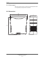
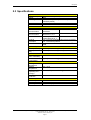
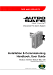
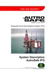
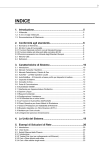
1
Interfacing BU-70 Display Units
and BU-100/BU-101 Panels
AutroSafe BU-70 Interface BSL-337
Protecting life, environment and property...
116-P-BSL337/EE, Rev. D, 2007-01-25
COPYRIGHT ©
This publication, or parts thereof, may not
be reproduced in any form, by any
method, for any purpose.
Autronica Fire and Security AS and its
subsidiaries assume no responsibility for
any errors that may appear in the
publication, or for damages arising from
the information in it. No information in this
publication should be regarded as a
warranty made by Autronica Fire and
Security. The information in this
publication may be updated without
notice.
Product names mentioned in this
publication may be trademarks. They are
used for identification purposes only.
Table of Contents
Table of Contents
1. Introduction.......................................................................3
1.1
1.2
1.3
About the Handbook ......................................................................... 3
The Reader ....................................................................................... 3
Reference Documentation ................................................................ 3
2. Description ........................................................................5
2.1
2.2
2.3
2.4
2.5
Functional description / application ................................................... 5
2.1.1 Messages transmitted from AutroSafe to BU-70 display
units and BU-100/BU-101 panels ........................................... 5
2.1.2 Messages transmitted to/from BU-100/BU-101 panels to
AutroSafe ................................................................................ 5
2.1.3 Messages related to different operation zones....................... 5
2.1.4 Printer support ........................................................................ 6
Dimensions........................................................................................ 6
Specifications .................................................................................... 7
Indicators and buttons....................................................................... 8
Connectors ........................................................................................ 9
3. Installation.........................................................................10
3.1
3.2
3.3
3.4
3.5
3.6
3.7
3.8
Hardware Requirements ................................................................... 10
Software Requirements..................................................................... 10
Installation Overview - up to 16 BU-panels....................................... 11
Installation Overview - more than 16 BU-panels............................... 12
Installation Overview – star-connection using a
communication line splitter................................................................ 13
Standard Communication Parameters.............................................. 14
EAU-321 Serial-Port Communication Board..................................... 14
3.7.1 Jumper Settings — EAU-321.................................................. 15
3.7.2 Termination by use of ribbon cable and standard screw
terminal block .......................................................................... 16
3.7.3 Termination by use of cable XBA-055 .................................... 16
RS-232 / Current Loop Communication............................................ 17
3.8.1 Overview ................................................................................. 17
3.8.2 The Autronica Standard Short Protocol (ASSP) ..................... 17
3.8.3 Current Loop / RS-232 Converter BSL-12/2........................... 17
3.8.4 Maximum length of communication lines................................ 18
3.8.5 Cable connections between BU-panels in the BS-100
system..................................................................................... 18
4. BSL_337 Installation.........................................................19
4.1
4.2
Two Types of Installation .................................................................. 19
4.1.1 Panel-Internal Installation ....................................................... 19
4.1.2 Panel-External Installation ...................................................... 19
Mounting and Connections ............................................................... 20
4.2.1 General Connection ................................................................ 20
4.2.2 Mounting the Current Loop/RS-232 Converter BSL-12/2....... 21
Interfacing BU70 Display Units and BU100/BU101 Panels, AutroSafe Interactive Fire-Alarm System,
116-P-BSL337/EE, Rev. D, 2007-01-25,
Autronica Fire and Security AS
Page 1
Table of Contents
4.2.3 Connections between the Current Loop/RS-232
Converter BSL-12/2 and BU-panels ....................................... 21
4.2.4 Mounting the Communication Line Splitter KDL-26B ............. 22
4.2.5 Connections between the Current Loop/RS-232
Converter and the Communication Line Splitter KDL-26B ..... 23
5. Configuring the AutroSafe System .................................24
5.1
5.2
Introduction........................................................................................ 24
Configuring the AutroSafe System.................................................... 24
6. Configuring BSL_337 .......................................................27
6.1
6.2
6.3
6.4
Settings on the Panel Front............................................................... 27
Service-Computer-Based Configuration ........................................... 27
Defining language and the total number of display units/panels ...... 28
Standard text strings ......................................................................... 29
7. Testing BSL_337 ...............................................................30
8. Testing the Final Installation ...........................................31
9. Appendix ...........................................................................32
9.1
9.2
Datasheet RS-232/Current Loop Interface BSL-12/2 ....................... 32
Datasheet Communication Line Splitter KDL-26B ............................ 33
10. Reader’s Comments .........................................................35
Interfacing BU70 Display Units and BU100/BU101 Panels, AutroSafe Interactive Fire-Alarm System,
116-P-BSL337/EE, Rev. D, 2007-01-25,
Autronica Fire and Security AS
Page 2
Introduction
1. Introduction
1.1 About the Handbook
This handbook provides all necessary information required to
interface BU-70 display units and BU-100/BU-101 parallel operation
panels in the BS-100 system to AutroSafe Fire-detection systems.
The BU-70 display units and BU-100/BU-101 parallel operation panels
are referred to as BU-panels in this handbook.
The purpose of the AutroSafe BU-70 Interface BSL-337 (hereby
called the BSL-337 interface) is to convert data transmitted from
AutroSafe, via a RS-232 serial connection using the AutroCom
protocol, into the proprietary communication protocol ASSP (Autronica
Standard Short Protocol for BU-panel communication).
In this way, information from the AutroSafe system can be shown on
displays on BU-panels, and RESET and SILENCE commands can be
sent from BU-100/BU-101 panels to the AutroSafe panel.
1.2 The Reader
This handbook is designed for use by Autronica Fire and Security
service personnel.
1.3 Reference Documentation
In addition to this handbook, Autronica Fire and Security offers the
following documentation:
Documentation
Datasheet
Product
AutroSafe BU-70
Interface BSL-337
RS-232/Current Loop
Interface BSL-12/2
Data Communication
Line Splitter
Display Unit BU-70
Datasheet (included
in Appendix)
Datasheet (included
in Appendix)
Installation,
Commissioning and
Operator’s Handbook
Installation,
Parallel Operation
Commissioning and Panel BU-100 and
Operator’s Handbook BU-101
Part number
116-P-BSL337/CE
116-P-BSL12/2/CE
116-P-KDL26B/CE
116-P-BU70/IE
116-P-BU100/EE
Interfacing BU70 Display Units and BU100/BU101 Panels, AutroSafe Interactive Fire-Alarm System,
116-P-BSL337/EE, Rev. D, 2007-01-25,
Autronica Fire and Security AS
Page 3
Introduction
Interfacing BU70 Display Units and BU100/BU101 Panels, AutroSafe Interactive Fire-Alarm System,
116-P-BSL337/EE, Rev. D, 2007-01-25,
Autronica Fire and Security AS
Page 4
Description
2. Description
2.1 Functional description / application
2.1.1 Messages transmitted from AutroSafe to BU-70 display units
and BU-100/BU-101 panels
The Autronica BSL-337 interface allows BU-panels (BU-70 display
units and BU-100/BU-101parallel operation panels) to be connected
to AutroSafe series fire-detection panels so that information from the
AutroSafe system is shown on the BU-panels’ displays, including:
•
•
•
•
•
Alarms
Prealarms
More alarms
LED On/Off
Reset commands (resetting all BU-panel tables and panels)
Note that the same messages, including detection zone and point
information, are displayed on all BU-panels.
2.1.2 Messages transmitted to/from BU-100/BU-101 panels to AutroSafe
RESET and SILENCE commands can be transmittet from the BU-100
panels (parallel operation panels) to the AutroSafe system by
operating the RESET button and SILENCE SOUNDER button (silence
alarm) on the BU-100 panel. Note that BU-101 only has a SILENCE
BUZZER button.
2.1.3 Messages related to different operation zones
If the AutroSafe system consists of a top level operation zone with
several sub-operation zones, messages related to a specific
AutroCom port, i.e. a specific operation zone, can be routed to a
group of BU-panels which physically belongs to this AutroCom
port/operation zone.
Interfacing BU70 Display Units and BU100/BU101 Panels, AutroSafe Interactive Fire-Alarm System,
116-P-BSL337/EE, Rev. D, 2007-01-25,
Autronica Fire and Security AS
Page 5
Description
2.1.4 Printer support
Note that the printer function on the BU-100 Parallel Operation Panel
is not supported by using the BSL-337 interface.
2.2 Dimensions
120
45
99
114.5
Interfacing BU70 Display Units and BU100/BU101 Panels, AutroSafe Interactive Fire-Alarm System,
116-P-BSL337/EE, Rev. D, 2007-01-25,
Autronica Fire and Security AS
Page 6
Description
2.3 Specifications
Physical
Dimensions (mm)
Weight
Mounting
Materials
Colour
Interface
Ports
BU-70communication
AutroSafe
communication
Service PC
Protocol
Convertion
Cable Terminals
Interface Options
Port 0 (to BU-70)
Port 1 (to EAU321)
Power
Power Supply
(from AutroSafe)
Current
Consumption
Environmental
Working
temperature
Storage
temperature
Relative humidity
(operating and
storage)
Level of
Protection
EMC Compliance
EMC Compliance
Emissions
Immunity
114,5 x 120 x 45 (HxDxW)
250g
TS-35 DIN-rail (internally or externally to
AutroSafe panels)
PC/ABS
Green
Two asynchronous ports + service port
Port 0
RS-232
1200 baud
Port 1
RS-232
9600 baud, 8, N, 1
Service port
RS-232
115200 baud, 8, N, 1
Port 0: Autronica Standard Short Protocol (ASSP)
Port 1: AutroCom protocol
Plug-in screw connection, maximum 2.5mm2
cable
RS-232 (maximum length 10m)
RS-232 (maximum length 10m)
18–32V DC
Typically 150–200mA @ 24V DC
–10–+60°C
–25–+70°C
10–95%, RH (non-condensing)
IP-20
IEC 60945
EN 50081-2 (94)
EN 50082-2 (95)
Interfacing BU70 Display Units and BU100/BU101 Panels, AutroSafe Interactive Fire-Alarm System,
116-P-BSL337/EE, Rev. D, 2007-01-25,
Autronica Fire and Security AS
Page 7
Description
2.4 Indicators and buttons
/ Language selection
= Switch in ON position
Name
PWR
Color
Green
FLT
Red
ST0
Yellow
TX1
RX1
Green
Red
TX0
RX0
AFB TX
AFB RX
AFB ST1
S1
Green
Red
S2
BCD High /
BCD Low
Description
Steady ON: Power OK
Note: The LED flickers slightly once every second. This is an indication that
the software is running.
Pulsating: Fault
The reason for the fault will normally be presented on the AutroSafe display as
a fault from BSD-337.
The Fault LED will also flash if the AutroSafe communication is lost.
Pulsating: Sending AutroSafe events to BU-panels (BU-70 and BU-100/BU101).
Application level indicator: The BSL-337 queues AutroSafe events , and this
LED can be lit continuously in periods with high traffic.
Pulsating: AutroCom data sent to AutroSafe
Pulsating: AutroCom data received from AutroSafe.
TX1/RX1: As a minimum, there will be communication every 3 seconds with a
brief flash in both LEDs.
Pulsating: data sent to BU-panels (BU-70 and BU-100/BU-101).
Pulsating: data received from BU-panels (BU-70 and BU-100/BU-101).
Not in use
Not in use
Not in use
DIP-switches for port 1 (to AutroSafe)
(S1.4 ON)
DIP-switches for port 0 BU-panels (BU-70 and
BU-100/BU-101), (S2.4 ON)
The rotary switches are used to determine both the language (addresses 6064) and the total number of BU-panels connected (addresses 01-16).
Refer to chapter 6.3.
BCD High
Language selection:
The switch determines the number of ten-digits (6).
Total number of BU-panels (BU-70 and BU-100/BU-101):
The switch determines the number of ten-digits (0 or 1)
BCD Low
Language selection:
This switch determines the number of one-digits (1-4).
Total number of BU-panels (BU-70 and BU-100/BU-101):
The switch determines the number of one-digits (0-9)
Interfacing BU70 Display Units and BU100/BU101 Panels, AutroSafe Interactive Fire-Alarm System,
116-P-BSL337/EE, Rev. D, 2007-01-25,
Autronica Fire and Security AS
Page 8
Description
2.5 Connectors
Function
Terminal
Terminal
The plug-in screw terminals are numbered 1 – 32.
1
2
3
4
5
6
7
NC
NC
NC
NC
NC
NC
NC
17
18
19
20
21
22
23
8
9
10
11
12
13
14
15
16
NC
NC
NC
NC
NC
TX, RS-232, Port 1
RX, RS-232, Port 1
Signal Reference Port 1
Instrument Earth Port 1
24
25
26
27
28
29
30
31
32
Function
NC
NC
NC
NC
Service port, Tx. RS-232
Service port, Rx. RS-232
Service port, Signal reference,
RS-232
NC
TX, RS-232, Port 0
RX, RS-232, Port 0
Signal Reference, Port 0
Instrument Earth, Port 0
+24V DC Input
0V DC Input
Instrument Earth, common
Protective Earth, common
* Additional service port connection on 3-pin plug connector by use of
service cable XJA-029
Connection 1–8
Connection 17–24
1
4
5
8
12 13
16
Connection 25–32
Connection 9–16
9
Interfacing BU70 Display Units and BU100/BU101 Panels, AutroSafe Interactive Fire-Alarm System,
116-P-BSL337/EE, Rev. D, 2007-01-25,
Autronica Fire and Security AS
Page 9
Installation
3. Installation
3.1 Hardware Requirements
In order to interface BU-panels to an AutroSafe system, the following
hardware is required:
• AutroSafe Serial Communication Board EAU-321 — port 1 or 2
(See section 3.7 and 3.8).
• AutroSafe BU-70 Interface BSL-337
• Current Loop/RS-232 Converter, BSL-12/2
• Cables: XBA-055 or XGK-1/20-30 with terminal block
• If more than 16 BU-panels are to be connected, additional
BSL-337 interfaces and Current Loop/RS-232 Converters
BSL-12/2 must be installed (refer to chapter 3.4).
3.2 Software Requirements
• AutroSafe system software version 3.2.0 or later
• AutroSafe AutroCom parameters:
- baud rate 9600
- 8 data bit
- none parity
- 1 stop bit
Interfacing BU70 Display Units and BU100/BU101 Panels, AutroSafe Interactive Fire-Alarm System,
116-P-BSL337/EE, Rev. D, 2007-01-25,
Autronica Fire and Security AS
Page 10
Installation
3.3 Installation Overview - up to 16 BU-panels
The following system blocks are referred to in this overview:
EAU-321
AutroSafe Serial Communication Board in
AutroSafe panel
AutroSafe BU-70 Interface
Current Loop/RS-232 Converter
Display Unit
Parallel Operation Panel
BSL-337
BSL-12/2
BU-70
BU-100/BU-101
A maximum of 16 BU-panels can be connected to an AutroCom port.
If the AutroSafe panel is to be connected to more than 16 display BUpanels, additional BSL-337 interfaces and Current Loop/RS-232
Converters BSL-12/2 must be connected to the other available
AutroCom port (refer to chapter 3.4).
AutroSafe
EAU-321
AutroCom
ASSP
BSL-337
RS-232
RS-232
24VDC
BSL-12/2
20mA Current
Loop
24VDC
BU-70
BU-100
BU-70
Interfacing BU70 Display Units and BU100/BU101 Panels, AutroSafe Interactive Fire-Alarm System,
116-P-BSL337/EE, Rev. D, 2007-01-25,
Autronica Fire and Security AS
Page 11
24VDC
Installation
3.4 Installation Overview - more than 16 BU-panels
The following system blocks are referred to in this overview:
EAU-321
BSL-337
BSL-12/2
BU-70
BU-100/BU-101
AutroSafe Serial Communication Board in
AutroSafe panel.
AutroSafe BU-70 Interface
Current Loop/RS-232 Converter
Display Unit
Parallel Operation Panel
If the AutroSafe panel is to be connected to more than 16 BU-panels,
an additional BSL-337 interface and Current Loop/RS-232 Converter
BSL-12/2 must connected to the other available AutroCom port. Up to
2 AutroCom ports can be used per AutroSafe panel, allowing a
system setup consisting of a maximum of 32 BU-panels.
AutroCom
RS-232
AutroSafe
Port 1
EAU-321
ASSP
BSL-337
RS-232
BSL-12/2
20mA Current
Loop
BU-70/
BU-100/101
1-16
Port 2
AutroCom
RS-232
24VDC
24VDC
ASSP
BSL-337
RS-232
BSL-12/2
20mA Current
Loop
BU-70/
BU-100/101
17-32
24VDC
24VDC
Interfacing BU70 Display Units and BU100/BU101 Panels, AutroSafe Interactive Fire-Alarm System,
116-P-BSL337/EE, Rev. D, 2007-01-25,
Autronica Fire and Security AS
Page 12
Installation
3.5 Installation Overview – star-connection using a
communication line splitter
The following system blocks are referred to in this overview:
EAU-321
BSL-337
BSL-12/2
KDL-26B
BU-70
BU-100/BU-101
AutroSafe Serial Communication Board
AutroSafe BU-70 Interface
Current Loop/RS-232 Converter
Communication Line Splitter
Display Unit
Parallel Operation Panel
The Communication Line Splitter KDL-26B can be used to split the
communication line from AutroSafe to BU-panels into 4 separate
communication lines. This is especially useful in distributed systems
where there are larger distances between system panels.
A system setup using the Communication Line Splitter KDL-26B
provides a more secure communication line, as a fault on one
communication line will not affect other communication lines.
Furthermore, in larger distributed systems a star-connection will ease
the installation.
Due to power consumption, a maximum of 10 BU-panels can be
connected to one communication line (recommended limitation). The
maximum number of BU-panels connected to each Communication
Line Splitter is 16.
If the AutroSafe panel is to be connected to more than 16 BU-panels,
an additional BSL-337 interface and Current Loop/RS-232 Converter
BSL-12/2 must connected to the other available AutroCom port. Up to
2 AutroCom ports can be used per AutroSafe panel, allowing a
system setup consisting of a maximum of 32 BU-panels.
AutroSafe
EAU-321
AutroCom
ASSP
BSL-337
RS-232
RS-232
24VDC
BSL-12/2
20mA Current
Loop
24VDC
KDL-26B
1
BU-70/
BU-100/101
BU-70/
BU-100/101
2
3
4
BU-70/
BU-100/101
Maximum 16 BU-panels
Interfacing BU70 Display Units and BU100/BU101 Panels, AutroSafe Interactive Fire-Alarm System,
116-P-BSL337/EE, Rev. D, 2007-01-25,
Autronica Fire and Security AS
Page 13
BU-70/
BU-100/101
Installation
3.6 Standard Communication Parameters
The BSL-337 is delivered from the factory containing the following
communication parameters:
• Port 0, to BU-70: 1200 baud
• Port 1, to AutroSafe: 9600 baud, 8 databit, none parity, 1 stop bit
3.7 EAU-321 Serial-Port Communication Board
The BSL-337 requires that the EAU-321 Serial-Port Communication
Board is installed in the relevant AutroSafe panel; this allows the
AutroSafe panel to communicate with BSL-337 using RS-232 on port
1 or 2.
The EAU-321 Serial-Port Communication Board, when installed, is
located as per figure:
Panel front
Processor
board
Communications boards:
LON-Interface board EAU-310 (if installed)
Serial-Port Communication Board EAU-321
Interfacing BU70 Display Units and BU100/BU101 Panels, AutroSafe Interactive Fire-Alarm System,
116-P-BSL337/EE, Rev. D, 2007-01-25,
Autronica Fire and Security AS
Page 14
Installation
3.7.1 Jumper Settings — EAU-321
20-19
J5
Port 4
2-1
Port 3
TX
RX
CT
DC
DS
R1
1
2
3
4
5
6
15
12
11
10
7
6
5
4
3
2
R
J6
TX
RX
CT
DC
DS
R1
1
2
3
4
5
6
Port 1
Port 2
J7
19-20
C
B
A
15
12
11
10
7
6
5
4
3
2
R
J8
1-2
15
12
11
10
7
6
5
4
3
2
R
J9
15
12
11
10
7
6
5
4
3
2
R
J10
J11
Note that J5 determines port 1, and J6 determines port 2; in an
application where port 1 is in use by other equipment, then J6 should
be set as shown in the diagram, to allow connection of the BSL-337
interface.
Important: It is important that the physical port used and the port you
configure in the software corresponds to eachother.
Interfacing BU70 Display Units and BU100/BU101 Panels, AutroSafe Interactive Fire-Alarm System,
116-P-BSL337/EE, Rev. D, 2007-01-25,
Autronica Fire and Security AS
Page 15
Installation
3.7.2 Termination by use of ribbon cable and standard screw terminal
block
J3
EAU-321
XGK-1/20-30
Port 1 and 2
20
19
9 (GND)
4
2
3
1
5 (Tx)
3 (Rx)
Terminal Block
The drawing shows an EAU-321 Port 1-connection. EAU-321 Port 2
may be used with connection terminals 13, 15 and 19.
3.7.3 Termination by use of cable XBA-055
Ribbon cable XBA-055 can be connected directly to the screw
terminal on BSL-337.
Interfacing BU70 Display Units and BU100/BU101 Panels, AutroSafe Interactive Fire-Alarm System,
116-P-BSL337/EE, Rev. D, 2007-01-25,
Autronica Fire and Security AS
Page 16
Installation
3.8 RS-232 / Current Loop Communication
3.8.1 Overview
The following system blocks are referred to in this overview:
EAU-321
BSL-337
BU-100/BU-101
BU-70
BSL-12/2
AutroSafe Serial Communication Board
AutroSafe BU-70 Interface
Parallel Operation Panel
Display Unit
Current Loop/RS-232 Converter
AutroSafe
EAU-321
BSL-12/2
AutroCom
BSL-337
RS-232
ASSP
RS-232
RS-232
20mA
20mA Current
Loop
Current Loop
Active transmitter
Active receiver
BU-70/
BU-100/101
1-16
24VDC
24VDC
3.8.2 The Autronica Standard Short Protocol (ASSP)
The BU-panels in the BS-100 system are prepared for 20mA current
loop communication with passive transmitter and passive receiver.
Autronicas internal protocol Autronica Standard Short Protocol
(ASSP) is used as the communication protocol for BU-panels.
3.8.3 Current Loop / RS-232 Converter BSL-12/2
Port 0 on the BSL-337 interface uses the ASSP communication
protocol. To enable communication between AutroSafe and
BU-panels, a current loop/RS-232 converter must be used. The
converter’s current loop must be configured and connected as an
active transmitter and active receiver.
For this purpose, the Current Loop/RS-232 Converter BSL-12/2 is
used. The converter is supplied with 24VDC power from the AutroSafe
system panel. The 24VDC power supplied from the AutroSafe panel
has battery backup.
Interfacing BU70 Display Units and BU100/BU101 Panels, AutroSafe Interactive Fire-Alarm System,
116-P-BSL337/EE, Rev. D, 2007-01-25,
Autronica Fire and Security AS
Page 17
Installation
3.8.4 Maximum length of communication lines
The recommended maximum length of the communication lines are
as follows:
RS-232 < 10 metres
20mA current loop < 1200 metres
3.8.5 Cable connections between BU-panels in the BS-100 system
For information regarding cable connections between BU-panels
(BU-70 display units and BU-100/BU-101 panels), refer to separate
documentation (116-P-BU70/IE and 116-P-BU100/IE).
Interfacing BU70 Display Units and BU100/BU101 Panels, AutroSafe Interactive Fire-Alarm System,
116-P-BSL337/EE, Rev. D, 2007-01-25,
Autronica Fire and Security AS
Page 18
BSL_337 Installation
4. BSL_337 Installation
The BSL-337 interface and RS-232/Current Loop Converter BSL-12/2
may be installed in one of two ways: internally or externally to the
panel to which it is connected.
4.1 Two Types of Installation
4.1.1 Panel-Internal Installation
Connect BSL-337 to the relevant port on the installed EAU-321 board;
install the unit directly onto the panel-internal DIN-rail. The module is
powered by the internal 24VDC power supply.
4.1.2 Panel-External Installation
The modules can also be placed on an external DIN-rail (outside of
the AutroSafe cabinet) and powered from AutroSafe or with an
external 24VDC power supply. Connect the unit to the relevant port on
the installed EAU-321 board. RS-232 distance limitations apply — i.e.
maximum 10 metres. If longer distances are required, a modem and
shielded cable are recommended (port 1 is insulated).
Interfacing BU70 Display Units and BU100/BU101 Panels, AutroSafe Interactive Fire-Alarm System,
116-P-BSL337/EE, Rev. D, 2007-01-25,
Autronica Fire and Security AS
Page 19
BSL_337 Installation
4.2 Mounting and Connections
Warning:
If you connect the power supply to the wrong terminals, the unit may be damaged. Make
sure that the BSL-337 and EAU-321 are connected to the AutroSafe power supply as
described in this chapter.
4.2.1 General Connection
Interfacing BU70 Display Units and BU100/BU101 Panels, AutroSafe Interactive Fire-Alarm System,
116-P-BSL337/EE, Rev. D, 2007-01-25,
Autronica Fire and Security AS
Page 20
BSL_337 Installation
4.2.2 Mounting the Current Loop/RS-232 Converter BSL-12/2
The Current Loop/RS-232 Converter BSL-12/2 has configurable
inputs and outputs. The converter is delivered as a separate circuit
board on a bracket prepared for mounting on a standard TS-35 rail.
77,5mm
55mm
135mm
4.2.3 Connections between the Current Loop/RS-232 Converter BSL-12/2
and BU-panels
All cables are connected to screwterminals.
If a system consists of more than one BU-panel, the BU-panels are
interconnected. For this information, refer to cable connections for
BU-70, BU-100/BU-101 described in the BS-100 documentation.
Interfacing BU70 Display Units and BU100/BU101 Panels, AutroSafe Interactive Fire-Alarm System,
116-P-BSL337/EE, Rev. D, 2007-01-25,
Autronica Fire and Security AS
Page 21
BSL_337 Installation
4.2.4 Mounting the Communication Line Splitter KDL-26B
The Communication Line Splitter KDL-26B is delivered as a separate
circuit board on a bracket prepared for mounting on a standard TS-35
rail.
Interfacing BU70 Display Units and BU100/BU101 Panels, AutroSafe Interactive Fire-Alarm System,
116-P-BSL337/EE, Rev. D, 2007-01-25,
Autronica Fire and Security AS
Page 22
BSL_337 Installation
4.2.5 Connections between the Current Loop/RS-232 Converter and the
Communication Line Splitter KDL-26B
The Communication Line Splitter KDL-26B is used to split the
communication line from AutroSafe to BU-panels into 4 separate
communication lines.
A maximum of 10 BU-panels can be connected to one communication
line (recommended limitation). The maximum number of BU-panels
connected to each Communication Line Splitter is 16.
The communication output lines must be configured as active
transmitter and active receiver. The communication lines in the
drawing below applies terminal outputs5-8, 9-12, 13-16 and 17-20.
Configuration of current loop
BSL-12/2
Current loop:
• Active transmitter
• Passive receiver
KDL-26B
Input:
• Active transmitter
• Passive receiver
Outputs:
• Active transmitter
• Active receiver
BU-70, BU-100, BU-101
Current loop:
• Passive transmitter
• Passive receiver
Interfacing BU70 Display Units and BU100/BU101 Panels, AutroSafe Interactive Fire-Alarm System,
116-P-BSL337/EE, Rev. D, 2007-01-25,
Autronica Fire and Security AS
Page 23
Configuring the AutroSafe
System
5. Configuring the AutroSafe
System
5.1 Introduction
AL ARM
Cable XJA-029
Cable XJA-033
Fire ext.. acktivated
Silence buzzer
Fire vent. activ.
Fire Brig. recvd.
More Alarms
Power
Prewarning
Early warning
Fault
System fault
Function disabled
Test
Silence sounders
Reset
1
2
3
4
5
6
7
8
9
C
0
?
Self Verify
AutroSafeConfig
The procedure deals with the configuration of the AutroSafe
Interactive Fire Alarm System. The AutroSafe Configuration Tool is
used for this purpose.
The chapter includes the following:
• Configuring the AutroSafe System
• Connecting the cable for downloading
• Downloading the AutroSafe Configuration
5.2 Configuring the AutroSafe System
The necessary configuration of the AutroSafe includes the following:
• From the Main Menu in AutroSafe Configuration Tool, click on
View and select System (System View).
• In the Tree View on the left side of the screen, click on the Panel
(BS-310/-320) where the AutroCom Serial is to be added.
Note: Make sure that the selected panel is actually the one where
the Serial Port Communication Board EAU-321 is mounted.
• Right-click the mouse and select Add.
Interfacing BU70 Display Units and BU100/BU101 Panels, AutroSafe Interactive Fire-Alarm System,
116-P-BSL337/EE, Rev. D, 2007-01-25,
Autronica Fire and Security AS
Page 24
Configuring the AutroSafe
System
• In the popup menu that appears, write the name of unit to be
added, and state the number of units to be added (if necessary).
BU-70
• Click on AutroCom Serial in the Entity window, then click on the
Add button.
• In the Tree View, click on the AutroCom Serial (in this example
named AUTROCOM_SERIAL_Pager).
Interfacing BU70 Display Units and BU100/BU101 Panels, AutroSafe Interactive Fire-Alarm System,
116-P-BSL337/EE, Rev. D, 2007-01-25,
Autronica Fire and Security AS
Page 25
Configuring the AutroSafe
System
• Select port number, 1 or 2.
• Verify the parameter settings (baud rate to 9 600 baud, 8 bits,
none parity, 1 stopbit).
• Set the AutroCom Type to SERIAL_SLIDING_WINDOW in the
drop-down box to the right.
• From the Main Menu, click on View and select Operation View.
• In the Tree View on the left side of the screen, click on the top level
OZ (Operation Zone) – that is, if there are several Operation Zones
in the AutroSafe system.
• Right-click the mouse and select Connect.
• In the popup menu that appears, select the Pager (in this example
we have given the Unit this name), then click on the Connect
button.
• In the Tree View, verify that the AutroCom Serial (in this example,
Pager) is connected to the correct OZ (Operation Zone).
Interfacing BU70 Display Units and BU100/BU101 Panels, AutroSafe Interactive Fire-Alarm System,
116-P-BSL337/EE, Rev. D, 2007-01-25,
Autronica Fire and Security AS
Page 26
Configuring BSL_337
6. Configuring BSL_337
6.1 Settings on the Panel Front
/ Language selection
= Switch in ON position
The DIP-switches and rotary switches should be set as shown in the
figure:
S1.4 ON (RS-232 on port 1)
S2.4 ON (RS-232 on port 0)
Rotary switches:
The switches are used to determine both the language (addresses 6064) and the the total number of BU-panels connected (addresses 0116).
Refer to the procedure; “Defining language and the total number of
display units/panels”, described in chapter 6.3.
6.2 Service-Computer-Based Configuration
The BSL-337 has very few configurable settings; language and port
parameter settings. Port parameter settings are modified by use of a
service computer connected to BSL-337’s service port, using a
standard AutroSafe Config Download cable (XJA-029), and then run
HyperTerminal.
Communication parameters for the service port is 115200 baud, 8
databit, no parity, 1 stop bit.
Interfacing BU70 Display Units and BU100/BU101 Panels, AutroSafe Interactive Fire-Alarm System,
116-P-BSL337/EE, Rev. D, 2007-01-25,
Autronica Fire and Security AS
Page 27
Configuring BSL_337
6.3 Defining language and the total number of
display units/panels
Perform the procedure in the following sequence (first define the
language, then the total number of BU-panels):
Step 1: Defining language
When defining the language, the rotary switches function as follows:
BCD high: This switch determines the number of ten-digits (6).
BCD low: This switch determines the number of one-digits (1-4).
• Set the switches according to the selected language:
Language
Address
English
Norwegian
Swedish
Danish
61
62
63
64
BCD high
ten-digits (6)
6
6
6
6
BCD low
one-digits (1-4)
1
2
3
4
Step 2: Defining the total number of BU-panels
• When the switches for the selected language are set, press the
reset button on the BSL-337 interface (the LEDs will start flashing).
When defining the total number of BU-panels, the rotary switches
function as follows:
BCD high: This switch determines the number of ten-digits (0-1).
BCD low: This switch determines the number of one-digits (0-9).
• Define the total number of BU-panels.
Address
01
02
03
04
05
06
07
08
09
10
11
12
13
14
15
16
BCD high
ten-digits (0-1)
0
0
0
0
0
0
0
0
0
1
1
1
1
1
1
1
BCD low
one-digits (0-9)
1
2
3
4
5
6
7
8
9
0
1
2
3
4
5
6
• When the switches are set, press the reset button once more (the
LED will change to a steady light).
Interfacing BU70 Display Units and BU100/BU101 Panels, AutroSafe Interactive Fire-Alarm System,
116-P-BSL337/EE, Rev. D, 2007-01-25,
Autronica Fire and Security AS
Page 28
Configuring BSL_337
Example:
The language to be selected is English, and the total number of
BU-panels are 16.
• Set the switches according to English language (61):
BCD high: 6, BCD low: 1
• Press the reset button on the BSL-337 interface (the LED will start
flashing).
• Set the switches according to a total of 16 BU-panels:
BCD high: 1, BCD low: 3
• When the switches are set, press the reset button once more (the
LED will change to a steady light).
6.4 Standard text strings
Alarm texts are defined by means of the AutroSafe configuration tool.
These texts include detection zone information (detector names) and
consist of a maximum of 34 characters.
Alarms and operation are indicated by short language-dependent
texts on the BU-panels’ displays. Text is shown only in the event of an
alarm or prealarm. Faults are shown by the activation of a LED
indicator.
Note that in the event of an alarm or a prealarm, the same text is
shown in all BU-panels (BU-70 display units and BU-100/BU-101
panels) connected to the same AutroSafe panel (i.e. connected to the
same AutroCom port and belonging to the same operation zone).
Interfacing BU70 Display Units and BU100/BU101 Panels, AutroSafe Interactive Fire-Alarm System,
116-P-BSL337/EE, Rev. D, 2007-01-25,
Autronica Fire and Security AS
Page 29
Testing BSL_337
7. Testing BSL_337
In order to verify that alarms, prealarms and faults are transmitted
from the BSL-337 interface, complete a simple system setup as
shown below.
AutroSafe
EAU-321
AutroCom
BSL-337
RS-232
RS-232
24VDC
BSL-12/2
20mA Current
Loop
BU-70
24VDC
24VDC
Perform the following procedure:
• Activate an alarm, prealarm and a fault on the AutroSafe system.
• Observe the following:
o Fire alarms and prealarms are presented in all BU-panel
displays with text, pulsating LEDs and buzzers.
o Faults are presented only with pulsating Fault LEDs and
buzzers.
o The buzzers can be silenced by pressing the SILENCE
BUZZER button on the BU-70 and BU-101 panel, or by
pressing the SILENCE SOUNDER button on the AutroSafe
panel or BU-100 panel.
o Pulsating LEDs will change to steady LEDs after pressing the
SILENCE SOUNDER button on the AutroSafe panel or
BU-panel.
o The LEDs will go off when pressing the RESET button on the
AutroSafe panel or BU-100 panel.
Interfacing BU70 Display Units and BU100/BU101 Panels, AutroSafe Interactive Fire-Alarm System,
116-P-BSL337/EE, Rev. D, 2007-01-25,
Autronica Fire and Security AS
Page 30
Testing the Final Installation
8. Testing the Final Installation
When the installation is completed, verify that all BU-panels show
alarms, prealarms and faults.
When the power is turned ON, the following startup message will
appear in the BU-70 display:
S1200
01
(c)90AUT.
Program Version
Panel address 00-15
Baud rate: 1200 Baud
When communication is established, the light in the display will go off
and remain dark.
Fault messages shown in BU panel's display during startup:
If the communication between BSL-337 and the BU panels is missing,
the following text is shown:
S1200 01 (c)90AUT.e83.
The fault message (e83) means that there is no communication. The
buzzer will be activated if the communication is missing during normal
operation. The FAULT LED-indicator will also be lit.
Fault messages shown in the AutroSafe panel's display during
startup:
If the communication between AutroSafe and the BSL-337 is missing,
the following text is shown::
"Loss of communication."
If the communication between BSL-337 and BU panels is missing, the
following fault message is shown::
”Protocol converter fault.”
Note that it is important to define a name for each AutroCom port
(EAU-321/BSL-337) that is used (maximum 2 per AutroSafe panel);
for example,
“Comm. BU-panels 1-6”.
In this way, it will be easier to locate the fault.
Interfacing BU70 Display Units and BU100/BU101 Panels, AutroSafe Interactive Fire-Alarm System,
116-P-BSL337/EE, Rev. D, 2007-01-25,
Autronica Fire and Security AS
Page 31
Appendix
9. Appendix
9.1 Datasheet RS-232/Current Loop Interface BSL-12/2
Interfacing BU70 Display Units and BU100/BU101 Panels, AutroSafe Interactive Fire-Alarm System,
116-P-BSL337/EE, Rev. D, 2007-01-25,
Autronica Fire and Security AS
Page 32
Appendix
9.2 Datasheet Communication Line Splitter KDL-26B
Interfacing BU70 Display Units and BU100/BU101 Panels, AutroSafe Interactive Fire-Alarm System,
116-P-BSL337/EE, Rev. D, 2007-01-25,
Autronica Fire and Security AS
Page 33
Reader’s Comments
10. Reader’s Comments
Please help us to improve the quality of our documentation by returning your comments on this
manual:
Title: Interfacing BU-70 Display Units and BU-100/BU-101 Panels,
AutroSafe Interactive Fire-Alarm System
Ref. No.: 116-P-BSL337/EE, Rev. D, 2007-01-25
Your information on any inaccuracies or omissions (with page reference):
Please turn the page
Interfacing BU70 Display Units and BU100/BU101 Panels, AutroSafe Interactive Fire-Alarm System,
116-P-BSL337/EE, Rev. D, 2007-01-25,
Autronica Fire and Security AS
Reader’s Comments
Suggestions for improvements
Thank you! We will investigate your comments promptly.
Would you like a written reply?
Name:
□ Yes □ No
------------------------------------------------------------------------------------------------
Title:
------------------------------------------------------------------------------------------------
Company:
------------------------------------------------------------------------------------------------
Address:
----------------------------------------------------------------------------------------------------------------------------------------------------------------------------------------------------------------------------------------------------------------------------------------------
Telephone:
------------------------------------------------------------------------------------------------
Fax:
------------------------------------------------------------------------------------------------
Date:
------------------------------------------------------------------------------------------------
Please send this form to:
Autronica Fire and Security AS
N-7483 Trondheim
Norway
Tel: + 47 73 58 25 00
Fax: + 47 73 58 25 01
www.autronicafire.com
Interfacing BU70 Display Units and BU100/BU101 Panels, AutroSafe Interactive Fire-Alarm System,
116-P-BSL337/EE, Rev. D, 2007-01-25,
Autronica Fire and Security AS
Autronica Fire and Security AS is an international company, based in Trondheim, Norway, and
has a world-wide sales and service network. For more than 40 years Autronica’s monitoring systems
have been saving lives and preventing catastrophes on land and at sea. Autronica Fire and
Security’s most important business area is fire detection and security. Autronica Fire and Security
stands for protecting life, environment and property.
Quality Assurance
Stringent control throughout Autronica Fire and Security assures the excellence of our products
and services. Our quality system conforms to the Quality System Standard NS-EN ISO 9001, and
is valid for the following product and service ranges: marketing, sales, design, development,
manufacturing, installation and servicing of
•
•
Fire-detection and security systems
petrochemical, oil and gas instrumentation systems for monitoring and control
In the interest of product improvement, Autronica Fire and Security reserves the right to alter
specifications according to current rules and regulations.
Autronica Fire and Security AS
Fire and Security, Trondheim, Norway. Phone: + 47 73 58 25 00, fax: + 47 73 58 25 01
Oil & Gas, Stavanger, Norway. Phone: + 47 51 84 09 00, fax: + 47 51 84 09 99
Division Maritime, Spikkestad, Norway. Phone: + 47 31 29 55 00, fax: + 47 31 29 55 01
Visit Autronica Fire and Security’s website: www.autronicafire.com