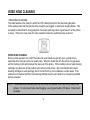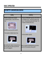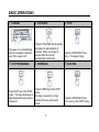
1
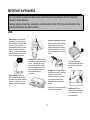
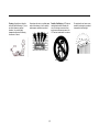
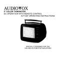
VIDEO CASSETTE PLAYER
DC OPERATION W/SPECIALIZED TAPE MECHANISM
DLC COATED VIDEO HEAD
BACKLIGHTING FUNCTION BUTTONS
AVP-7000 OPERATING INSTRUCTIONS
SPECIALLY DESIGNED FOR VAN, RV, MARINE,
RECOMMENDED GUIDELINES FOR USE OF A VIDEO MONITOR/TV IN A MOTOR VEHICLE
A VIDEO/MONITOR/TV is designed for rear passenger viewing only.
This product may be installed in the rear seat compartment of the vehicle, out of the driver’s view.
• Installation in any other area of the vehicle, including anywhere within the driver’s view, is illegal in
most states, provinces and countries and may lead to driver distraction resulting in an accident, injury
and/or death. If you are unsure of regulations regarding this, you should consult your local laws to
determine how this applies to you.
• Users should be aware of the possible noise distraction caused by the use of the product and should
carefully monitor the volume so as not to interefere with the driver’s attention to surrounding traffic
conditions.
CONTENTS
IMPORTANT SAFEGUARDS………………….3
SPECIAL OPERATION……………………………..12
IMPORTANT NOTES…………………………..6
IDENTIFICATION………………………….………..13
FEATURES……………………………………...7
CONNECTION……………………………………….17
MOISTURE CONDENSATION………………..8
BEFORE CALLING SERVICE PERSONNEL…….20
VIDEO HEAD CLEANING……………………..9
TROUBLE SHOOTING………………………………21
BASIC OPERATIONS………………………..10
SPECIFICATIONS……………………………………23
Thank you for purchasing AUDIOVOX VCP, developed advanced features and functions for high quality
performance.
To obtain the best results and to avoid malfunction, please read the following instructions carefully
before using.
WARNING: TO PREVENT ELECTRIC SHOCK, DO NOT EXPOSE THIS APPLIANCE TO RAIN OR MOISTURE
AVERTISSEMENT: POUR PREVENIR LES RISQUES D’INCENDIE ET D’ELECTROCUTION, NE PAS EXPOSER CET
APPAREIL ℵ LA PLUIE NI ℵ L’HUMIDIT⊃.
CAUTION: TO PREVENT ELECTRIC SHOCK DO NOT USE THIS (POLARIZED) PLUG WITH AN EXTENSION CORD,
RECEPTACLE OR OTHER OUTLET UNLESS THE PLUG CAN BE FULLY INSERTED WITHOUT
EXPOSING ANY PARTS OF THE BLADES.
ATTENTION: POUR ⊃VITER LES CHOCS ⊃LECTRIQUES, NE PAS UTILISER CETTE FICHE (POLARISEE) AVEC
UN CORDON PROLONGATEUR, UNE PRISE DE COURANT OU UNE AUTRE SORITE DE COURANT,
SAUF SI LES BROCHES PEUVENT ⊇TRE INSEREES ℵ FOND SANS QU’AUCUNE PARTIE NE RESTE
ℵ D⊃COUVERT.
The lightning flash with the arrowhead symbol, within an
equilateral triangle, is intended to alert the user to the
presence of uninsulated “dangerous voltage” within the
product’s enclosure that may be of sufficient magnitude to
constitute a risk of electric shock to persons
CAUTION
RISK OF ELECTRIC
SHOCKS DO NOT OPEN
CAUTION: TO REDUCE RISK OF ELECTRIC SHOCK,
DO NOT REMOVE COVER (OR BACK).
NO USER-SERVICEABLE PARTS INSIDE.
REFER SERVICING TO QUALIFIED PERSONNEL.
The exclamation point within an equilateral triangle is
intended to alert the user to the presence of important
operating and maintenance (servicing) instructions in the
literature accompanying the VCP.
1
Note to CATV system Installer:
This reminder is provided to call the CATV
system installer’s attention to Article 820-40 of the
ote to CATV
NEC that provides guidelines for proper
grounding and, in particular, specifies that the
cable ground shall be connected to the grounding
system of the building, as close to the point of
cable entry as practical.
2
NOTE:
This equipment has been tested and found to comply
with the limit for a Class B digital device, pursuant to
Part 15 of the FCC Rules. These limits are designed to
provide reasonable protection against harmful
interference in a residential installation.
This equipment generates, uses and can radiate radio
frequency energy and is not installed and used in
accordance with the instructions may cause harmful
interference to radio communications. However, there
is no guarantee that interference will not occur in a
particular installation. If this equipment does cause
harmful interference to radio or television reception,
which can be determined by turning the equipment off
and on, the user is encouraged to try to correct the
interference by one or more of the following measures:
- Reorient or relocate the receiving antenna.
- Increase the separation between the equipment and
receiver.
- Connect the equipment into an outlet on a circuit
different from that to which the receiver is
connected.
- Consult the dealer or an experienced radio/TV
technician for help.
IMPORTANT SAFEGUARDS
For your protection, please read these safety instructions before operating the VCP and keep this
manual for future reference.
Carefully observe all warnings, precautions, and instructions on the VCP or the ones described in the
operating instructions and adhere to them.
USE
Power Sources- This set should be
operated only from the type of power
source indicated on the marking label.
If you are not sure of the type of
electrical power supplied at your home,
consult your dealer or local power
company. For those sets designed to
operate from battery or other sources,
refer to the operating instructions.
Object and Liquid Entry- Never push
objects of any kind into the set through
the openings as they may touch
dangerous voltage points or short out
parts that could result in fire or electric
shock. Never spill liquid of any kind on
the set.
Accessories- Do not place the set on
an unstable cart, stand, tripod, bracket,
or table. The set may fall, causing
serious injury to a child, or an adult,
and serious damage to the set. Use
only a cart stand tripod, bracket, or
table recommended by the
manufacturer.
-Never block the slots and
openings by placing the set on a
bed, sofa, rug or other similar
surface.
Ventilation- The slots and openings in
the cabinet are provided for necessary
ventilation. To ensure reliable
operation of the set, and to protect it
from overheating, these slots and
openings must never be blocked or
covered.
Water and Moisture- Do not use
power line operated sets near waterfor example, near a bathtub, washbowl,
kitchen sink, or laundry tub, in a wet
basement, or near a swimming pool,
etc.
-Never cover these slots and openings
with a cloth or other materials.
3
Attachments- Do not use
attachments not recommended
by the manufacturer, as they
may cause hazards.
Cleaning- Unplug the set from the
wall outlet before cleaning it. Do not
use liquid cleaners or aerosol
cleaners. Use a cloth lightly
dampened with water for cleaning
the exterior of the set.
-Never place the set in a confined space
such as a bookcase, or built in cabinet,
unless proper ventilation is provided.
4
Portable Cart Warning- VCP and cart
combination should be moved with
care. Quick stops, excessive force,
and uneven surfaces may cause the
VCP and cart combination to overturn.
-Do not place the unit near or over
a radiator, heat register, or where it
is exposed to direct sunlight.
SERVICE
Damage Requiring Service- Unplug the set
from the wall outlet and refer servicing to
qualified service personnel under the
following conditions:
-If the set has been subject to excessive shock
by being dropped, or the cabinet has been
damaged.
Servicing-Do not attempt to service the set
yourself as opening or removing covers may
expose you to dangerous voltage or other
hazards.
Refer all servicing to qualified service personnel.
-When the power cord is damaged or frayed.
-If liquid has been spilled or objects have
fallen into the set.
-If the set does not operate normally when
following the operating instructions. Adjust only
those controls that are specified in the operating
instructions. Improper adjustment of other
controls may result in damage and will often
require extensive work by a qualified technician
to restore the set to normal operation.
Replacement parts- When replacement parts are
required, be sure the service technician has used
replacement parts specified by the manufacturer
that have the same characteristics as the original
parts.
Unauthorized substitutions may result in fire,
electric shock, or other hazards.
Safety Check- Upon completion of any service or
repairs to the set, ask the service technician to
perform routine safety checks (as specified by the
manufacturer) to determine that the set is in safe
operating condition.
-If the set has been exposed to rain or water.
- When the set exhibits a distinct change in
performance this indicates a need for service.
5
Important Notes
• Note that main voltage is supplied to the unit whenever the main plug is connected to the power
supply socket.
• To avoid the risk of electric shock, do not expose the unit to rain or moisture.
• Do not attempt to open the cabinet. There are no user-serviceable parts inside. Refer all servicing to
qualified service personnel.
• Keep the unit away from radiators or other sources of heat.
• Do not operate or store this unit close to strong magnetic fields.
• Do not spill liquid of any kind onto this unit. If liquid is accidentally spilled onto the unit, immediately
remove the main plug from the supply socket, and consult a qualified service engineer.
• Avoid places subject to strong vibration.
• Do not place anything heavy on the VCP.
• Use the video player in a horizontal (flat) position only.
• Before operating, remove any paper wrapping which may have been affixed to the VCP during
manufacture. DO NOT COVER VENT OPENINGS ON TOP AND SIDES OF THE PLAYER DURING
OPERATION.
• When a cassette is inserted into the loading compartment, the power is switched on automatically as
long as the power cord is plugged into a DC outlet. DO NOT force a cassette into the compartment
when the power cord is unplugged.
• After playing a video cassette, remove it from the player. DO NOT move the player with a video
cassette in the compartment.
• Store video cassettes in their sleeve or case and position them vertically.
For your protection, record the model number
and serial numbers of your video cassette player
here. In the event your player requires servicing
or is stolen, you may need this information. You
may also wish to clip or staple your sales receipt
to this page.
Model Number:_______________________________
Serial Number:_______________________________
Date Purchased:_____________________________
Store’s Name and Address:
___________________________________________
___________________________________________
6
Features
1. DIGITAL AUTO TRACKING
This VCP plays clear pictures without special operations.
In the Auto tracking mode the play lamp will blink.
2. SELF PICTURE ADJUSTMENT
Since the HEAD DRUM rotates regularly independent of voltage change or tape condition, the picture
is always stable.
3. AUTO START FEATURE
The VCP will automatically power on and go into PLAY mode when a cassette is inserted.
7
MOISTURE CONDENSATION
¬ At room temperature, if you
- Moisture condensation may
® When the moisture
pour ice water into a glass,
water vapor will condense on
the surface of the glass.
This moisture is condensation.
The moisture condensation may
occur inside of VCP’s. If used
in this condition, it will cause
damage to the head and the
tape.
occur when the VCP is moved
from a cold place to a heated
place, the temperature of
surroundings goes up due to the
heat being switched on, or moving
the VCP suddenly from an air
conditioned room to a place of
high humidity.
condensation occurs inside the
VCP, NEVER insert the tape
into the cassette compartment.
Remove the cassette, if
loaded, by pressing the
STOP/EJECT button. Only
operate the VCP after the
moisture has completely dries
out. This normally takes about
1 hour.
8
VIDEO HEAD CLEANING
VIDEO HEAD CLOGGING
The video heads are the means by which the VCP reads pictures from the tape during playback.
In the unlikely event that they become dirty enough to be clogged, no picture will be played back. This
can easily be determined if, during playback of a known good tape, there is good sound, but the picture
is snowy. If this is the case, have the video cassette checked by qualified service personnel
VIDEO HEAD CLEANING
During normal operation of the VCP the video and audio heads can get dirty over a period of time,
especially when using an old or poor quality tape. When the heads are dirty the picture can get snowy
and the tracking control will not adjust the snow out of the picture. If this condition occurs, head cleaning
cartridges may take care of this problem and restore normal picture. We recommend that the head
cleaning cartridges be used sparingly due to the fact that they can be abrasive to video heads. If the
problem is not resolved with the head cleaning cartridge then the unit needs to be checked by qualified
service personnel.
NOTE: Video heads may eventually wear out and should be replaced when they fail to produce clear
pictures. To help prevent video head clogging, use only good quality VHS tapes. Discard worn
out tapes.
9
BASIC OPERATION
CASSETTE LOADING/UNLOADING
Loading
• Push the cassette into the cassette
compartment gently. (Arrow mark at the
top)
Unloading
• Press the STOP/EJECT key twice on the VCP (in
PLAYBACK mode). This first press will stop the
tape. The second press will eject the tape. The
cassette-in indicator will be lit up.
An inverted cassette cannot be inserted.
• The cassette-in indicator lamp is lit up.
Upon inserting the cassette, the power turns on
even if the power was off as long as the DC
power cord is plugged in.
• Pull the cassette out gently.
When you press the STOP/EJECT key even if the
power is off, the cassette will be ejected.
10
BASIC OPERATIONS
¬ LOADING
- PLAYBACK
The power is on automatically
when the cassette is inserted
even if the power is off.
Press the PLAY key and the picture
will appear in approximately 8
seconds. When end of tape is
reached then the unit will
automatically rewind tape.
¯ FAST FORWARDING
° REWINDING
± EJECTING
Press the FF key in the STOP
mode. The tape advances at a
high speed without any picture
and sound.
Press the REW key in the STOP
mode.
The tape is rewound at a high
speed without any picture and
sound.
Press the STOP/EJECT key
once more (in the STOP mode).
11
® STOP
Press the STOP/EJECT key
once. The tape will stop.
SPECIAL OPERATIONS
The VCP enters the playback mode during special operations as soon as the PLAY key is pressed.
During special operations noise bars and loss of color may affect the picture. This is not a fault with this
unit.
¬ TO VISUALLY SEARCH
- TO VISUALLY SEARCH
® TO OPERATE RE-AUTO
FORWARD
REVERSE
TRACKING
• Press the FF key once in the
playback mode. Then the
tape advances rapidly with
the pictures. Press this key
once more, and the tape will
advance at a high speed.
• Press the REW key once in
playback mode. Then the tape
is rewound rapidly with the
pictures. Press this key once
more and the tape will rewind
at a high speed.
12
• Press the PLAY key during
playback and then the VCP
enters the Re-Auto Tracking
mode.
IDENTIFICATION
FRONT PANEL
¬ Cassette Compartment
® Stop/Eject key
Press this key to stop tape and once more to
eject tape.
- Power key
When power is supplied to the set, the power
indicator lamp will always light up in red.
The Power ON and Power OFF mode will be
toggled by pressing this key.
When the POWER is switched on, the power
lamp will light up in red and the other keys will
light up in green.
¯ Rewind/Review key
If this key is pressed in the PLAYBACK mode,
the VCP enters the reverse picture search
mode. If pressed in STOP mode, then the tape
will rewind at high speed. The REW indicator
lamp will light up in orange.
13
° PLAY KEY
Press this button to playback a recorded
tape, or to release special operations such
as the search modes.
In the playback mode the indicator playback
Lamp will be ON in orange, and in the AUTO
tracking mode this indicator lamp will blink.
² CASSETTE-IN LAMP
When the cassette is inserted, the CST-IN lamp
will light up in green.
³ DEW LAMP
This indicator will flash (if power is on) to indicate
excessive moisture has been inside of VCP.
Unit will not operate till it dries out sufficiently
(the tape can be ejected from unit). When DEW
mode has been activated, leave unit on to allow
it to dry out completely. This will take
approximately 1 hour.
± FAST FORWARD/CUE KEY
If this key is pressed in PLAYBACK mode
the VCP enters the forward picture search
mode. If FF is pressed while tape is in
STOP mode then unit will fast forward at
high speed. When the FF key is pressed,
the indicator lamp will light up in orange.
14
REAR PANEL
1
5
¬ FUSE HOLDER
2
6
3
4
7
8
- RF OUT CHANNEL SELECTION SWITCH
The main line fuse is accessible with the
External fuse holder simply by unscrewing the
cap. If the main line fuse should blow then
replace the fuse with a proper rated fuse (125V,
2A).
15
Set the channel to 3 or channel 4, whichever is
not being broadcast in your area.
® ANT. IN
For connecting the TV antenna to this terminal.
¯ VIDEO OUT
Connect this terminal to VIDEO IN terminal of your television, using the RCA cord provided.
° AUDIO OUT
Connect this terminal to AUDIO IN terminal of your television, using the RCA cord provided.
± RF OUT
For connection to the antenna terminal of a TV receiver through the coaxial cable.
²³ DC JACK IN
Connect this jack to DC source (DC 12V).
NOTE: This VCP is for 12V use only so do not use it in 24V vehicles.
If you use this set in a 24V vehicle, all of the lamps will blink. To avoid the malfunction of this set
please disconnect the plug from the power source.
16
VCP TO VEHICLE CONNECTION
• You can apply this method to DC 12V output only.
• Please connect to the vehicle only after making sure of the polarity of the cigarette lighter socket.
(negative earth)
17
HOW TO USE THIS METHOD
•
•
•
•
•
•
You can apply this method to only DC 12V output.
If you apply more than 18 volts then the power will automatically turn off.
Please connect after making sure of the polarity of the cigarette lighter socket.
If the polarity is reversed the unit will not operate.
Use of this VCP is not recommended in excessive heat.
If inside temperature of vehicle is over 100 F do not use VCP. Allow VCP to cool before use.
18
AUTO TRACKING ADJUSTMENT
• Since this VCP has the Auto Tracking Adjustment function, it can play clear pictures without special
operations.
• Auto Tracking Adjustment operates automatically when the cassette is inserted.
• Playback indicator lamp blinks during auto tracking operation. If the tracking is completed, the playback
indicator lamp lights on.
• If noise bars appear in the picture during playback, press the PLAY key to operate Re-Tracking
function.
NOTE: This VCP has an Auto Start Feature.
This VCP will automatically power on and go into PLAY mode when a cassette is inserted.
HI-FI
STEREO
PLAY KEY
19
BEFORE CALLING SERVICE PERSONNEL
SYMPTOMS
CAUSE
POSSIBLE SOLUTIONS
POWER
• The power cord is not
connected
• The polarity of power cord is
not connected
• Connect the power cord.
• The TV is not set to the video
channel, 3 or 4.
• Tracking is not adjusted.
• Set your TV to the video
channel, 3 or 4.
• Adjust the picture to be clear
by pressing the PLAY key.
Operation keys do not work.
• If the cassette or the VCP is
not in normal condition, every
indicator LED/LAMP is lit up
and the VCP does not work.
Cassette is ejected upon
inserting
• Safety device works to protect
the cassette when it is
inserted incorrectly.
• Turn off the power and turn on
the power again by pressing
the POWER key.
• Unplug and re-plug the power
cord.
• Pull the cassette out
(unloading) and insert it firmly
into the cassette
compartment.
NO POWER
• Change the polarity of the
power cord.
PLAYBACK
No picture on screen when
playing back a recorded tape.
Noise bars on screen
OTHERS
20
TROUBLESHOOTING
SYMPTOMS
NO POWER
No back lighting at power button.
Power indicated with back
lighting- unit will not operate.
Mode indicators flashing unit will
not operate
Play mode indicated no audio or
video to TV
CAUSE
POSSIBLE SOLUTIONS
Check CH Video Switch is in ON
position.
NO 12VDC
• Check circuit fuse at source of
power (see vehicle/converter
manual).
• In-line fuse of power cord (in
lighter plug).
• VCP (2 amp *20x 5mm) fuse
located on rear of unit.
• Power cord unplugged from
12V outlet or at rear of unit.
(Unit in dew mode) Dew feature
• Retain power to payer and
activated (see owner’s manual)
allow unit time to rid moisture.
(After 30 minutes if dew
indicator still on, completely
switch power supply off from
unit and re-supply after 1
minute. This can reset dew
indicator if moisture
eliminated.)
No tape in unit
• Insert tape
Low Voltage
• Start vehicle, if not running
Unit in emergency mode.
• Contact dealer for service to
player
VCP connected to A/V Input jack, • Switch TV to video mode with
RCA patch cables set in TV
remote or switch behind door
mode.
of TV.
21
SYMPTOMS
Play mode indicated no audio or
Video to TV
CAUSE
VCP connected by (75Ù coax)
antenna coax to TV.
Set in “monitor mode”
VCP connected to A/V output
jacks. (AVT-1400 or 1475)
Play mode indicated- No audio or Output of VCP A/V RCA cables
video to TV.
or coax not connected to TV
(continued from previous page)
input.
Switchable input device used
between TV and VCP (game
prep)
Poor connection between VCP
and TV input.
Reversed A/V inputs to TV
Shorted Coax cable between
VCP and TV.
Poor Video/Snowy picture or
Dirty heads
lines on screen.
22
POSSIBLE SOLUTIONS
• Switch to TV mode
• Change connections from A/V
output to A/V input
• Check connections between
VCP and TV.
• Check connection (a)
• Check connection (b)
• Check cable/bypass or
continuity test
• Clean head using tape
cartridge cleaner. We
recommend using cartridge
with cloth or paper tape and
cleaning drops included.
• These are readily available at
retail stores
SPECIFICATION
MODEL
POWER SUPPLY
POWER CONSUMPTION
DIMENSION
WEIGHT APPROX.
VIDEO SIGNAL SYSTEM
VIDEO SIGNAL, OUTPUT (RF) VHS
TAPE TYPE
TAPE SPEED
FF/REW TIME (T-120)
VIDEO SIGNAL OUTLINE (LINE)
AUDIO SIGNAL OUTPUT (LINE)
OPERATING CONDITION HUMIDITY
OPERATING POWER VOLTAGE
AVP-7000
DC 12V
12W
265 X 91 X 295 (W X H X D)mm
3.4 kg
NTSC COLOR
75Ù unbalanced AVX.
VHS TYPE
SP 33.35mm/sec,
LP 22.23mm/sec, SLP 11.12mm/sec
Approx. 5 MIN.
1 Vpp 75Ù unbalanced
NEG. SYNC
-5dBm 10k Ù MAX
85% Rhmax
TEMPERATURE: 5C~35C (41F~95F)
12~14V
23
ACCESSORY LIST
Description
AVT-988 9” Color Television with Remote (12V)
AVT-597 5” Color Television with Remote (12V)
AVT-1498 13” Color Television with Remote (12V)
AVP-7000 Video Cassette Player (12V)
AVP-7285 video Cassette Player (12V)
Wireless Headphone Kit: Includes 2 sets Wireless Headphones and Transmitter
BPA-501-12 4 Amp Adapter for use with AVT-988 9” and AVT-1498 13” Televisions
AC2A- 2 Amp Adapter for use with AVT-597 5” TV and AVP-7000 Video Cassette
Player
Unified Remote Control
VAC-21- 12 Volt Corded Vacuum
AVF-1 12 Volt Rechargeable Flashlight
HP-175 Headphones with Pivoting Ear Cup
HP-275 Headphones with Volume Control on Cord
HP-375 Studio Quality Headphones
Part Number
AVT988
AVT597
AVT1498
AVP7000
AVP7285
WRFKIT1
0891412
0891436
0892325
VAC21
AVF1
HP175
HP275
HP375
Unlike household electronics, all of our products have been specifically designed and tested for the
mobile environment and are only available through ASA. To order any of these products, please contact
Audiovox Specialized Applications at www.asaelectronics.com or 800-688-3135.
24
90 DAY/12 MONTH LIMITED
WARRANTY
APPLIES TO AUDIOVOX VIDEO PRODUCT
Audiovox Specialized Applications, LLC (the company) warrants to the original retail purchaser of this product that
should this product or any part thereof, under normal use and conditions, be proven defective in material or
workmanship within 90 days from the date of original purchase, such defect(s) will be repaired or replaced (at the
company’s option) without charge for parts and repair labor. After the initial 90 day period and for a period of 12
months from the date of the original purchase, the company will supply at no charge a replacement for any
defective part(s), but will charge for the labor to repair the product.
To obtain repair or replacement within the terms of this warranty, the product is to be delivered with proof of warranty coverage (e.g.
dated bill of sale), specification of defect(s), transportation prepaid, to an approved warranty station, or the Company at the address
shown below.
This warranty does not extend to the elimination of externally generated static or noise, to the correction of antenna problems, to
costs incurred for removal or reinstallation of the product, or to damage to any tapes, speakers, accessories, or electrical systems.
This warranty does not apply to any product or part thereof which, in the opinion of the company, has been damaged through
alteration, improper installation, mishandling, misuse neglect or accident. THE EXTENT OF THE COMPANY’S LIABILITY UNDER
THIS WARRANTY IS LIMITED TO THE REPAIR OR REPLACEMENT PROVIDED ABOVE, AND , IN NO EVENT , SHALL THE
COMPANY’S LIABILITY EXCEED THE PURCHASE PRICE PAID BY THE PURCHASER FOR THE PRODUCT.
This warranty is in lieu of all other express warranties or liabilities. ANY IMPLIED WARRANTIES, INCLUDING ANY IMPLIED
WARRNTY OF MERCHANTABLILITY, SHALL BE LIMITED TO THE DURATION OF THIS WARRANTY. ANY ACTION FOR
BREECH OF ANY WARRANTY HEREUNDER, INCLUDING ANY IMPLIED WARRANTY OF MERCHANTABILITY MUST BE
BROUGHT WITHIN A PERIOD OF 30 DAYS FROM THE DATE OF ORIGINAL PURCHASE. IN NO CASE SHALL THE COMPANY
BE LIABLE FOR ANY CONSEQUENTIAL OR INCIDENTAL DAMAGES FOR BREECH OF THIS OR ANY OTHER WARRANTY,
EXPRESS OR IMPLIED, WHATSOEVER. No person or representative is authorized to assume for the company any liability other
than expressed herein in connection with the sale of this product.
Some states do not allow limitations on how long an implied warranty lasts or the exclusion or limitation of incidental or
consequential damages so the above limitations or exclusions may not apply to you. This warranty gives you specific legal rights.
You may also have other rights which vary from state to state.
Audiovox Specialized Applications, LLC
23319 Cooper Drive, Elkhart, IN 46514
For Service Information Call: 1-800-688-3135
U
L
This instrument is listed by Underwriter’s
Laboratories, Inc. It is designed and manufactured
to meet rigid U.L. safety standards against Xradiation, fire, casualty and electrical haxards.
Audiovox Specialized Applications, LLC
23319 Cooper Drive
Elkhart, IN 46514
(219) 264-3135