1
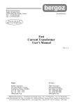
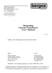
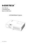
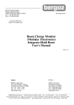
Accurate and Efficient C-V Measurements
Application Note E5250A-3
Agilent E5250A Low Leakage Switch Mainframe
Introduction
For next generation ULSI development,
precise characteristics evaluation of
semiconductors during device development, process development, and
circuit design phase is essential. As
well as IV measurement, C-V measurements are very important to determine
the oxide thickness. Other important
parameters such as substrate impurity
concentration can also be calculated
from C-V measurement results.
Also, improvement of test productivity
is mandatory for faster IC development.
This application note explains how
to perform accurate and efficient
C-V characteristics measurements
of multiple devices by changing connections using the Agilent E5250A
Matrix Switch.
Difficulties in Device
Characterization
On Test Element Groups (TEG), there
are various devices. They are for dc
characteristics measurements and
for C-V measurements. So, to improve
test efficiency, it is necessary to automate the changing of measurement
instrument connections and multiprobing on the wafer. A switching
matrix is required to automate
switching measurement instruments
and test devices.
Until now, there has been no suitable
switching matrix for precise low current measurements and accurate
capacitance measurements. Using
existing switching matrices, the performance of measurement instruments
was sacrificed. C-V measurement
results included big error due to the
residual impedance in the extension
cables and matrices. It was also difficult to compensate for the measurement error.
For precise testing, you had to perform IV and/or C-V measurements on
separate probing stations. There was
no adequate matrix available to combine these into one probe station.
Therefore, the biggest issue was that
measurement productivity was lowered
because you had to manually switch
measurement instruments and devices.
Figure 1. Agilent 4156C, 4284A, and E5250A with wafer prober
OUTPUT
1
2
3
4
5
6
7
8
9
10
11
12
INPUT
Instrument Connection
Low Leakage Path
SMU 1
SMU 2
SMU 3
SMU 4
SMU 5
HF 1
CV 1
SMU 6
HF 2
C-V Path
CV 2
Figure 2. E5250A Matrix Switch block diagram
Solution Using the Agilent E5250A
Low Leakage Switch Mainframe
The Agilent E5250A Low Leakage
Switch Mainframe provides the
solutions to those problems. There
are two types of plug-in modules:
Option 001 10 × 12 Matrix Switch
Module and Option 501 24-channel
Multiplexer Module.
The 10 × 12 Matrix Switch Module can
be used for precise parametric test.
It improves measurement efficiency
by eliminating the need to manually
change the probing positions on a
manual probe station. Figure 2 shows
the block diagram of Matrix Switch
Module. The Agilent E5250A has four
slots, so you can configure a 10-input
and 48-output matrix switch by using
Agilent ICS, you can easily automate
switching measurement instruments
and test devices.
four modules. There are six SMU input
terminals. The SMU1 and SMU2 inputs
are specially designed for low current
measurements. Using with the Agilent
4156C, you can measure sub pA level
current accurately. The CV1 and CV2
inputs are designed to be used with
capacitance measurement instruments
such as Agilent 4284A Precision
LCR Meter.
The Agilent E5250A Matrix Switch
Module has special capacitance compensation routine for accurate measurements, which can be used with the
Agilent 4284A. It is available as an
Agilent IBASIC subroutine or with
Agilent E5230B Interactive Characterization Software (Agilent ICS). By
using the Agilent E5250A with
Agilent E5250A Matrix Switch
Figure 3 shows an example connection
of Agilent 4284A, E5250A, 16495A/B
Connector Plate, and a probing station. The Agilent 4284A is connected
to the input terminals CV1 and
CV2 of E5250A by using the Agilent
16048D/E 4-terminal pair test lead.
The high potential and high current
terminals are connected together
using a T-connector. The low potential and low current terminals are
also connected together. This means
4-terminal pair connection is terminated at the input of E5250A and
2-terminal pair connection is used
after the matrix switch. Though
2-terminal pair connection has a
slightly narrower coverage of measurement impedance range than
4-terminal pair, it makes the device
probing easier.
For the output of the matrix switch,
the Agilent 16494A Triaxial Cables
are used to connect to the Agilent
16495A/B connector plate. The connector plate should be fixed to the wall
of shield box that surrounds probing
station. From the connector plate
to the probe card or probe needles,
Agilent P/N 8120-4461 low noise
coaxial cable is used. Note that the
triaxial and coaxial cables should
have same length for high and low
terminal for capacitance compensation. In general, using shorter cables
improves measurement accuracy.
Agilent 16495F/G Connector Plate (Fixed to Shield Box)
Probing Station
Agilent 4284A
LCR Meter
4284A 20 Hz - 1 MHz
PRECISION LCR METER
P/N 1250-2405
Male to
E5250A
Agilent 16048D/E
Test Lead
Female
to 16048X
Agilent 16494A
Opt 001/002
1.5/3 m Triax Cable
Female
to 16048X
P/N 8120-4461
Coax Cable < 2 m
Figure 3. Instruments connection for capacitance measurement
2
Agilent 16495F/G Option 002
Connector Plate
Figure 5 shows measurement circuit
diagram of Agilent 4284A including
matrix switch and cables. The connector plate is used as a part of return
path for the measurement signal current. The compensation calculation is
performed assuming the outer shield
of triaxial cables are connected to each
other at connector plate as shown in
Figure 5. If you use a connector plate
other than Agilent 16495A/B, such as
a connector plate that has an insulator
between the outer shields of the triaxial
connectors, the compensation may be
incorrect.
Agilent 8120-4461 Low Noise
Coaxial Cable
Common
Guard
Force
Jacket
Outer conductor
Semiconductor layer
Insulator
Inner conductor
As for the necessary instruments and
accessories, refer to Table 1. Ordering
Example, on page 8.
Triaxial Connector
Figure 4. Soldering coax cable to the Agilent 1645A/B connector plate
Maximum lengths for triaxial and
coaxial cables are 3 m and 2 m,
respectively.
The Agilent P/N 8120-4461 coaxial
cable has a semiconductor layer to
minimize the triboelectricity generated by frictional motion at boundary
between the conductor and insulator.
This special design enables you to
perform accurate dc measurements
through this cable as well as capacitance measurement.
To connect this cable to the connector plate, it is necessary to isolate the
inner conductor from the semiconductor layer. To do this, cut the semiconductor layer and insulator as
shown in Figure 4. Then solder inner
conductor to force terminal of a triaxial connector and outer conductor to
guard terminal.
Device Connection
When connecting LCR meter to measurement capacitors on semiconductor
wafers, you need to take the device
structure and LCR meter’s measurement circuit into account.
Note that dangerous voltage may
appear at the force and guard terminals. To prevent electric shock, cover
the triaxial connectors with metal
cover. Install an interlock circuit to
stop dangerous voltages when door
of shield box is open.
Capacitance compensation is performed based on F matrix calculation
for matrix and cables. Predetermined
values of residual impedance and
stray admittance per cable length are
used. Therefore, if you use other than
recommended cables, compensation
cannot be performed correctly.
Agilent 4284A
Because the ammeter is in the low side
of the circuit, as shown in Figure 5,
LCR meter’s low terminal is more
sensitive to noise than the high terminal. Therefore, for example, connect the high terminal to the wafer
chuck of prober or to the substrate
terminal on wafer, which generally has
wider antenna area to gather noise
than small gate area in case of oxide
capacitance measurements. For more
tips, please refer to Tips for More
Accurate Capacitance Measurements.
Agilent 5250A
Matrix switch
H cur
Agilent 16495F/G
Connector plate
High
V
H pot
L cur
A
Low
L pot
Wafer
Wafer chuck
~
Noise
Figure 5. Connection of high and low terminals
3
Agilent 4284A LCR Meter
are not calibrated by open/short
calibration. In general, load calibration should be additionally
performed in such a case. But,
for wafer measurements, it is very
difficult to have stable and accurate load, so you should perform
compensation as described next
instead of load calibration.
Agilent E5250A Matrix Switch
4284A 20 Hz - 1 MHz
PRECISION LCR METER
Agilent 16495F/G
Connector Plate
Agilent 16048D/E
Test Lead
Probe card/
needles
Agilent 16494A
Triax Cable
Open/Short
Calibration
Agilent 8120-4461
Coax Cable
E5250A Compensation
Offsec C
Subtraction
• E5250A/Output Cables Compensation
Specify cable length of the Agilent
16494A Triaxial Cable and Agilent
P/N 8120-4461 Coaxial Cable in
the capacitance compensation
routine. Its usage is described
later.
Figure 6. Compensation theory
Instead of load calibration, the
routine compensates the measurement error generated by residuals
in the matrix switch modules and
output cables. As long as you use
recommended cable, you can easily
compensate the error by specifying
the cable length.
Short Calibration
The outer conductor of coaxial cables
works as a shield to minimize stray
capacitance between center conductors and circuit common. The outer
conductors should be extended as
close as possible to measurement
device without contacting anything
(i.e., should be floating). Note that
they work as guard terminals in case
of dc measurements, that are to minimize leakage current.
4284A
4284A 20 Hz - 1 MHz
PRECISION LCR METER
42091A
16048D/E
Open Calibration
4284A
E5250A
4284A 20 Hz - 1 MHz
PRECISION LCR METER
CV1
CV2
16048D/E
1250-2405
Cable Calibration and Compensation
For accurate capacitance measurements, perform the following three
steps shown in Figure 6.
• Open/Short Calibration of
Agilent 16048D/E Test Lead
Perform open/short calibration at
the end of the Agilent 16048D/E
Test Lead on the Agilent 4284A’s
front panel. To perform short calibration, use the Agilent 42091A
Short Termination adapter to
connect high and low terminals
together as shown in Figure 7. For
open calibration, attach the test
leads to the CV1 and CV2 input
terminals of E5250A. All matrix
switch relays should be open.
Figure 7. Open/short calibration
Open/short calibration can be
done to the end of the 4-wire connection (16048D/E). If a matrix
switch and cables are used, they
Figure 8. Agilent 4284A configuration setup
4
• Probe Card/Needles Offset
Capacitance Subtraction
Perform a measurement of offset
capacitance caused by probe card
or probe needles. This cannot be
compensated by E5250A’s compensation calculation, so it should
be actually measured and subtracted from device capacitance
value. Don’t connect measurement
device during offset capacitance
measurement.
Figure 9. Setup editor
Capacitance Measurement
Using Agilent ICS
To measure capacitance using Agilent
ICS, perform the following steps. The
C-V driver (Agilent E5232B) and Matrix
Switch driver (Agilent E5233B) must
be installed with Agilent ICS.
Figure 10. Agilent 4284A Setup dialog box
• Agilent 4284A Configuration Setup
Set the Agilent 4284A configuration as shown in Figure 8. Specify
appropriate GPIB address, and
select Option 001 for dc bias and
Option 006 for 2 m/4 m cable length
in the Agilent 4284A Configuration
dialog box. If using the 16048D,
specify 2 m in Cable Length field.
In case of 16048E, specify 4 m.
• Measurement Algorithm
Figure 9 is an example Setup
Editor setting for C-V measurement of MOSFET gate oxide capacitor. Connect CMH (High terminal)
and CML (Low terminal) to substrate and gate, respectively. This
connection minimizes the noise
effect at wafer chuck.
Figure 11. Agilent E5250A Capacitance
Compensation dialog
Click CMH icon to open the Agilent
4284A Setup dialog box, which is
shown in Figure 10. In this example,
substrate voltage is swept from
+5 V to –5 V with step –0.5 V. Note
that we apply reverse bias to the
substrate. In this dialog box, you
can specify oscillation level, measurement frequency and integration
time too. These are very important
settings for accurate measurement,
which is discussed on page 7. Note
that if you enable capacitance
compensation (next step), parallel
circuit mode is used, so capacitance
and conductance are measured in
parallel mode.
• Capacitance Compensation
Click Agilent E5250A Compensation
button. A dialog opens as shown
in Figure 11. Enable capacitance
compensation. Then specify the
triaxial cable length (Agilent E5252
Output) and coaxial cable length
(After Connector Plate) in meters.
In this example, they are 1.5 m
and 1.0 m, respectively. You need
to measure your cables and use
the correct lengths.
Figure 12. Matrix Switch setup
5
• Setup Matrix Switch
Figure 12 is the matrix switch setup
dialog box, which allows you to
easily control the matrix switches.
Click cross point boxes of switchings to close. This example setup is
for the gate-substrate capacitance
of a MOSFET. CMH is connected
to the substrate terminal and CML
is connected to gate.
• Invert Bias Polarity
Transform Editor enables you to
define functions to calculate data
vectors or parameters. We apply
reverse staircase voltages to substrate in C-V measurement. So it
is necessary to calculate the difference of potential between gate and
substrate by defining a function as
shown in Figure 13. In this example,
gate voltage is defined as VGATE
vector. You can define any other
functions to analyze measured data
too in this dialog box.
• Subtract Offset Capacitance
Measure offset capacitance of probe
card and/or probe needles. Move
probe needles off wafer so needles
are not connected to anything. After
sweeping substrate voltages, open
data window spreadsheet and determine average offset capacitance
value as shown in Figure 14.
C_COMP shows the compensated
offset capacitance vector data.
Figure 14. Data window
Then enter the negative average
value of offset capacitance in the
B field in E5250A C Compensation
dialog as shown in Figure 15. In
this example, average offset capacitance was 2.337 pF.
• C-V Measurement
Perform C-V measurement of
Gate-Substrate capacitor. Contact
the probe needles on the wafer,
then measure. A graph of compensated capacitance value versus
gate voltage will be drawn in a plot
window. An example measurement
result is shown in Figure 16. The
Agilent E5250A Matrix Switch only
adds an additional 1% error so you
can perform accurate capacitance
Figure 13. Transform editor
Figure 16. C-V measurement example
6
Figure 15. Register offset cap
measurements even when using
the matrix.
Automated Test Using Agilent ICS
Agilent ICS enables you to automate
your tests. You can have multiple
measurement setups in one project
of ICS. By using the Auto Sequence
function, you can sequentially perform
selected measurements. Figure 17
shows the Auto Sequence dialog box
to define sequence of tests. In this
example, the project has five measurement setups and four setups are
selected to be executed. Using this
function with E5250A matrix switch,
you can automate tests including
IV and C-V measurements.
Figure 17. Sequence setup
Compensation Using Agilent
IBASIC Program
Capacitance compensation routine
is available as a sample program
on a diskette furnished with Agilent
E5250A Switch Mainframe.
Tips for More Accurate
Capacitance Measurements
• Wafer Chuck Capacitance
In general, wafer chuck should be
isolated from circuit common and
ground. This means it should have
higher impedance at the measurement frequency. A common problem
is measurement error due to large
capacitance between wafer chuck
and circuit common. Thermal chuck
(or so called hot chuck) has larger
capacitance. As the wafer size
became larger, the wafer chuck
sizes increased, so the chuck capacitance became larger too. This error
cannot be compensated by open/
short calibration or E5250A compensation. The error is in proportion to w2 LcableCchuck ,
where:
w is defined as 2πƒ,
ƒ is measurement frequency,
Lcable is inductance in cables between
matrix switch and device,
and Cchuck is capacitance between
wafer chuck and circuit common.
To minimize the error, use well isolated
wafer chuck and make the measurement cables shorter. Using lower frequency is most effective. If you use
ICS, set the frequency value in 4284
Setup dialog box shown in Figure 10.
Case A
CM H
Structure
An advantage of using this routine is
that you can modify the cable parameters used in compensation calculation so that you can use cables other
than Agilent 16494A or P/N 8120-4461.
Measure your cable parameters and
modify the parameter values in compensation routine.
Figure 18. Automated test example
Case B
CM L
N+
• Device Structure
Figure 19 shows typical device
structures for oxide capacitance
measurements. In general, most
accurate capacitance measurement can be done on structure A
because measurement device is
isolated from wafer chuck by NP
junction. Structure B is better than
C because structure B has higher
impedance (Rcontact and Cchuck) at
wafer chuck. Measurement data
of structure A also includes error
due to series resistance. If possible,
change device structure so that
wafer chuck does not affect the
device measurement.
CM H
Case C
CM L
CM L
N well
P substrate
Hot Chuck
P substrate
Hot Chuck
P substrate
Hot Chuck
CM H
CM H
Circuit
You can use the routine as a subprogram of Agilent BASIC or Agilent
Instrument BASIC. By specifying
cable lengths, measurement frequency,
and raw capacitance and conductance
data as parameters to the subprogram,
you can obtain compensated data.
CM H
CM H
C dut
CM L
C dut
C dut
R contact
CM L
R contact
C chuck
R contact
C chuck
CM L
C chuck
Figure 19. Device connection
7
Table 1. Ordering Example
E5250A
(*)
001
301
16494A
4284A
4156A
001
003
(*)
001
006
(*)
010
16495B
002
8120-4461
16048E
1250-2405
42091A
10833A
10833B
E5230B
E5231B
E5232B
E5233B
Low Leakage Switch Mainframe
10 x 12 Matrix Switch Card (E5252A)
Relay Function Test Adapter
Triaxial Cable
Triaxial Cable (1.5 m)
Triaxial Cable (80 cm)
Precision LCR Meter
Power Amplifier/ DC Bias
Compensation for 2 m /4 m Cable
Precision Semi. Para. Analyzer
Delete Kelvin Triaxial Cable Set
Connector Plate
Connector to contacts to soldering
Low noise coaxial cable
BNC Test Cable for 4284A (4 m)
BNC T-Connector for 16048E Cable
Standalone Short Termination
GPIB Cable (1 m)
GPIB Cable (2 m)
Interactive Characterization Software
IV Driver Library
CV Driver Library
Switch Driver Library
1
4+
1
52+
48+
4
1
1
1
1
1
2+
2+
2m x 48 +
1
2
1
2
1
1
1
1
1
* Select appropriate power line and localization options.
+ Decide appropriate numbers upon usage
A PC with supported GPIB interface is needed for ICS operation.
• Measurement Circuit Mode
If your device has large resistance
in series, it may be necessary to
convert measured parallel capacitance (Cp) and conductance (G)
values obtained by E5250A capacitance compensation to the capacitance (Cs) and resistance (Rs)
values of a series equivalent
circuit. Calculate as follows:
Cs = (1 + D 2) Cp
D2
1
Rs = –––––– × ––
G
1 = D2
G , ω = 2πf, and f is
where D = –––––
ωCp
measurement frequency.
• Noise Reduction
If your test room is electrically
noisy, do the following:
–Surround your wafer prober with
complete shield to prevent outside
electrical noise from going in, and
use shorter measurement cables.
–Use longer integration time to
average measurement errors.
Using higher test signal (oscillation) level is also effective because
signal-noise ratio will be higher.
Set them appropriately in 4284A
Setup dialog box (Figure 10)
in ICS.
Conclusion
By using Agilent E5250A’s Matrix
Switch Modules with capacitance
compensation for the Agilent 4284A
LCR Meter, you can perform accurate
capacitance measurements. Combining
with Agilent 4155C/4156C Parameter
Analyzer and Agilent ICS enables you
to integrate a low cost automatic
parametric test system for efficient
and accurate characterization and
evaluation of multiple devices.
Note: The information contained in
this application note is also applicable to the Agilent 4155A/4156A and
Agilent 4155B/4156B.
For more information about Agilent
Technologies semiconductor test products,
applications, and services, visit our website:
www.agilent.com/go/semiconductor
or you can call one of the centers listed
and ask to speak with a semiconductor
test sales representative.
For more information about other Agilent
test and measurement products, go to
www.agilent.com
United States:
1 800 452 4844
Canada:
1 877 894 4414
Europe:
(31 20) 547 2000
Japan:
(81) 426 56 7832
Fax: (81) 426 56 7840
Latin America:
(305) 269 7500
Fax: (305) 269 7599
Australia/New Zealand:
1 800 629 485 (Australia)
Fax: (61 3) 9272 0749
0 800 738 378 (New Zealand)
Fax: (64 4) 495 8950
Asia Pacific:
(852) 2599 7889
Fax: (852) 2506 9233
Taiwan:
(886 2) 717 9524
Fax: (886) 2 718 9860
Korea:
(822) 769 0800
Fax: (822) 786 1083
Singapore:
(65) 1 800 292 8100
Fax: (65) 275 0387
Product specifications and descriptions in this
document subject to change without notice.
Copyright © 2000 Agilent Technologies
Printed in U.S.A. 11/00
5965-5658E