1
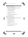
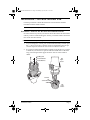
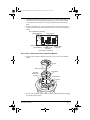
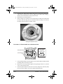
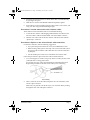
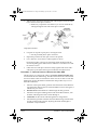
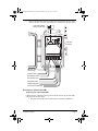
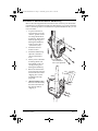
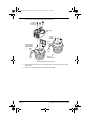
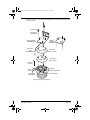
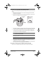
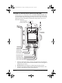
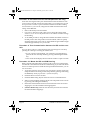
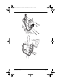
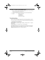
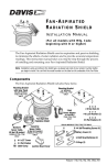
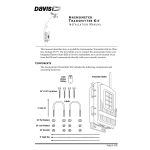
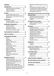
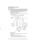
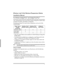
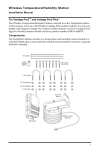
ISS2 SPARS RetroKit D011.fm Page 1 Wednesday, April 23, 2003 11:26 AM
V A N T A G E P R O ® A N D VA N T A G E P R O P L U S ™
F a n - A s p i r a t e d I S S R e t r o f it K i t
I ns t a l la t io n I n s t r u c t io n s
E s t im a t e d Ti m e R eq u ir e d : 6 0 M i n ut es
These instructions describe how to install the Vantage Pro® Fan-Aspirated
Integrated Sensor Suite (ISS) Retrofit Kit.
This retrofit kit applies to all cabled and wireless versions of the fan-aspirated
ISS.
Components
The Fan-Aspirated ISS Retrofit Kit includes the following components:
• Externally-mounted SIM with housing
• Temperature/Humidity sensor module
• Rain Collector cable extension
• New SIM Power cable
• Splice kit to attach extension cables
• Mounting hardware for new SIM housing
Tools for Setup
In addition to the kit, you will need the following tools:
• Small Phillips-head screwdriver
• Pliers or other crimping tool
• Other hand tools depending on your installation
Tip: If your Wireless Fan-Aspirated ISS has been in service for over a year, this would
be a good opportunity to replace the C-cell batteries used by the fan.
Installation Outline
Early version of the fan-aspirated ISS mounted the sensor interface module
internally inside the radiation shield. Newer versions of the fan-aspirated ISS
mount the SIM module in an external housing. The installation procedure for
the two different versions are outlined separately below.
CAUTION: Please work on your Vantage Pro ISS in a safe place. We strongly recommend
that you remove the ISS from its installed position before beginning these steps.
Product # 6921, 6921C
ISS2 SPARS RetroKit D011.fm Page 2 Wednesday, April 23, 2003 11:26 AM
ISS With Internally Mounted SIM
These are the procedures required to install the Fan-Aspirated ISS Retrofit Kit
on an ISS that has the SIM mounted inside the radiation shield. More detailed
directions are provided on the following pages.
1.
Remove the ISS from its installed position.
2.
Disconnect all cables from the old Sensor Interface Module (SIM) and
remove the SIM from the radiation shield.
3.
Mount the new Temp/Hum module.
4.
Re-assemble the radiation shield.
5.
Locate and cut the rain collector cable.
6.
Splice on the rain collector cable extension.
7.
Connect sensor cables to the new SIM.
8.
Power the SIM.
9.
Decommission the Old SIM (Wireless models only).
10. Test Communication between the ISS and the console.
11. Mount the ISS and the SIM Housing.
12. Return the old SIM to Davis.
ISS With Externally Mounted SIM
These are the procedures required to install the Fan-Aspirated ISS Retrofit Kit in
an ISS that has the SIM mounted in an external housing. More detailed directions are provided on the following pages.
1.
Remove the ISS from its installed position.
2.
Open the radiation shield.
3.
Mount the new Temp/Hum module.
4.
Re-assemble the radiation shield.
5.
Disconnect all cables from the old SIM.
6.
Connect sensor cables to the new SIM.
7.
Power the SIM.
8.
Decommission the Old SIM (Wireless models only).
9.
Test Communication between the ISS and the console.
10. Mount the ISS and the SIM Housing.
11. Return the old SIM to Davis.
Page 2
ISS2 SPARS RetroKit D011.fm Page 3 Wednesday, April 23, 2003 11:26 AM
Installation - ISS with Internal SIM
Use these procedures to install the retrofit kit on an ISS that has the SIM
mounted inside the radiation shield.
Note:Use this procedure if your ISS has wing nuts on the bottom.
Procedure 1. Remove the ISS from its Installed Position.
In order to take down your ISS you will first need to disconnect the anemometer
cable. If you have a Cabled Vantage Pro station, you will also need to disconnect
the console cable from the ISS.
CAUTION:Please work on your Vantage Pro ISS in a safe place.
1.
At your Vantage Pro console, press and hold the DONE key and then press
the “-” (down arrow) key to put the console in Setup Mode. This will prevent the reception of erroneous rain counts from the rain collector.
2.
If you have mounted the anemometer remotely from the ISS or if you have
a cabled ISS you will need to open the radiation shield. Remove the three
wing nuts and separate the upper and lower sections of the radiation
shield.
#8 Wing Nuts
#8 Lock Washers
#8 Flat Washers
ISS
Upper
Section
Fan Plate
Junction Board
ISS
Lower
Section
Installation Outline
Page 3
ISS2 SPARS RetroKit D011.fm Page 4 Wednesday, April 23, 2003 11:26 AM
3.
Locate the SIM inside the upper section of the radiation shield.
Sensor Interface Module
(SIM)
Solar Power Cable
(wireless models only)
Sensor Interface Cable
4.
Disconnect the WIND sensor (anemometer) cable.
5.
If you have a cabled station, you will also need to disconnect the Console
cable from the SIM.
6.
You can now remove the ISS from its mounted position. Move it to a safe
place to install the kit components.
Procedure 2. Disconnect all cables from the SIM and remove the
SIM.
The Sensor Interface Module (SIM) consists of a PC board and cover. The SIM
contains the ISS’s sensor and communications electronics.
Transmitter ID Switches
Anemometer
WIND RAIN SOLAR UV
Console Cable
(cabled models only)
Rain Collector Cable
Solar Radiation Cable
UV Sensor Cable
3-Volt
Lithium Battery
(wireless models only)
Sensor Interface
Cable
SIM Power Cable
(wireless models only)
Fan-Aspirated Radiation Shield SIM Cable Connections
1.
Page 4
Unplug all cables from the SIM.
Installation - ISS with Internal SIM
ISS2 SPARS RetroKit D011.fm Page 5 Wednesday, April 23, 2003 11:26 AM
2.
The SIM transmitter board, dust cover, and rear cover plate (not shown) are
attached to the top radiation shield plate using 4 screws. Unfasten these
screws and remove the dust cover along with the board and mounting
plate.
3.
Remove the SIM power cable, solar panel cable and the Sensor Interface
Cable from the junction board located in the lower section of the radiation
shield.
Solar and SIM Power Connectors
(Wireless ISS Only)
+VSIM
Fan Connector
MOTOR
+VSOL
+5V
TACH
T/H & SIM
AC Power Adapter Connector
(Cabled ISS Only)
Temp/Hum Sensor
Connector
Sensor Interface
Connector
Junction Board Connections
Procedure 3. Mount the New Temp/Hum Module
1.
Remove the fan and fan deflector from the lower section of the radiation
shield.
Fan Unit
Motor Connector
Fan Deflector
Temp/Hum
Sensor Cable
Channel
Junction Board
Fan Plate
2.
Remove the old Temp/Hum module from the radiation shield and unplug
it from the junction board.
Installation Outline
Page 5
ISS2 SPARS RetroKit D011.fm Page 6 Wednesday, April 23, 2003 11:26 AM
3.
Install the new Temp/Hum module, being sure to set the sensor cable in the
cable channel in the fan plate. The new Temp/Hum module cable will plug
directly into the SIM instead of the junction board.
4.
Reinstall the fan and fan deflector.
5.
The new SIM power cable has a brown terminal at one end and a white terminal at the other end. Plug the brown terminal of the new SIM power cable into
the junction board connector labeled +VSIM.
Installing the Temp/Hum Sensor
Procedure 4. Re-assemble the radiation shield.
Junction Board Cover
Press in on Sides
near latches
to Remove Cover
Junction Board
1.
Line up the threaded rods on the upper section of the radiation shield with the
mounting holes in the lower section.
2.
Slide the two sections partially together, leaving enough clearance so you have
access to the junction board.
3.
Check the Junction Board connections: fan motor, SIM power and Solar (SOL)
power (wireless models), AC-power adapter (cabled models).
Page 6
Installation - ISS with Internal SIM
ISS2 SPARS RetroKit D011.fm Page 7 Wednesday, April 23, 2003 11:26 AM
4.
Install the Junction Board cover as shown above. The cover installs easily
by pressing it into place.
5.
Slide the two sections of the Radiation Shield completely together.
6.
Fasten the two sections together using the 3 flat washers, lock washers, and
wing nuts. The wing nuts should be finger-tight.
Procedure 5. Locate and cut the rain collector cable.
These cables must be extended in order to reach the SIM housing.
1.
Locate the rain collector cable hanging underneath the rain collector base.
The rain collector cable is labeled “RAIN” near the modular connector.
2.
Take the wire cutters and cut the rain collector cable next to the modular
“phone-style” connector.
Procedure 6. Splice on the rain collector cable extension.
For the best connection, note the following suggestions:
• Try to place the spliced connections in a location shielded from rain.
• When securing cables, place a cable clip or tie on each side of the connection point so the movement of the cables does not cause the connection
to pull apart.
• Use the smaller splice connectors to extend the rain collector cable.
Follow this procedure to splice on the rain collector cable extension:
1.
Use a wire stripper or a knife to strip away about 1½ inches (38 mm) of the
jacket (the outer covering) of the cable.
Do not strip away any of the colored insulation on the individual wires.
Repeat this procedure for the end of each cable you are connecting.
Strip Shielding
2.
Take a wire from one of the cables and place it into one of the holes at the
end of a splice connector.
Make sure you push the wire all the way in. You can check this by looking
through the clear side of the splice connector.
Installation Outline
Page 7
ISS2 SPARS RetroKit D011.fm Page 8 Wednesday, April 23, 2003 11:26 AM
3.
Take the same colored wire from the other cable and place it into the other
hole at the end of the splice connector.
✦ Make sure you push the wire all the way in. You can check this by
looking through the clear side of the splice connector.
Using Splice Connector
4.
Use pliers to snap the cap into place, securing the wires.
5.
Repeat this procedure for each pair of wires to be spliced.
✦ Use the provided yellow splice connectors.
6.
Use a cable tie to secure the two cables together as shown.
Doing this provides a measure of strain relief which should prevent the
wires from pulling apart under normal conditions. Cut off the excess cable
tie when it is secure.
7.
Gather the wires and splice connectors neatly together and secure with a
cable tie in a protected location up close under the rain collector base.
Procedure 7. Connect Sensor Cables to the New SIM.
The ISS sensors are connected by cables to the Sensor Interface Module (SIM),
located inside the new SIM housing. The SIM contains electronics that measure
and store weather values for transmission to the console via cable or radio. The
SIM housing protects the SIM from the elements and provides easy access to
SIM cable connections.
1.
2.
3.
4.
5.
Page 8
Take one of the square rubber grommets from the bottom of the SIM housing and run the cables for the UV and Solar Radiation sensors through it, if
included on your station.
Wireless ISS: Run the SIM Power cable through this first grommet.
Take the second square rubber grommet and run the Rain Collector, Anemometer, and Temp/Hum sensor cables through it.
Cabled ISS: run the console cable through this second grommet.
Install the first grommet in the left slot in the SIM housing, and install the
second grommet in the right slot, adjusting the inside cable lengths as
needed for a tidy installation.
Installation - ISS with Internal SIM
ISS2 SPARS RetroKit D011.fm Page 9 Wednesday, April 23, 2003 11:26 AM
6.
Refer to the ISS SIM Connections illustration and connect only the sensor
cables as shown. You will connect the power cables in the next procedure.
3-Volt Lithium Battery
(wireless models only)
Transmitter
ID Switches
UV
UV
SUN RAIN WIND
TEMP
SUN RAIN WIND HUM
SIM Power Cable
(wireless only)
UV Sensor Cable
Solar Radiation Cable
Rain Collector Cable
Anemometer Cable
Temp/Humidity Cable
Console Cable (cabled only)
Procedure 8. Power the SIM.
Powering the Cabled ISS SIM
Cabled versions of the ISS receives power from the console via the 100’ (30m)
cable that runs between them.
• Plug the console cable into the SIM connector labeled “CONSOLE”.
Installation Outline
Page 9
ISS2 SPARS RetroKit D011.fm Page 10 Wednesday, April 23, 2003 11:26 AM
Powering the Wireless ISS SIM
Wireless versions of the ISS receive most of their power from the solar panel
installed next to the rain collector. Backup power is provided by a 3-volt lithium
battery.
Battery Holder
(Wireless Only)
Console Cable Connector
(Cabled Only)
ON
1 2 3 4
DIP Switch #4
DavisTalk Transmitter ID DIP Switch Settings
1.
Install the new battery in the SIM. The green test LED should blink once on
power up.
2.
Check that the DavisTalk transmitter DIP switches on the new transmitter
board match those on the old board. Change the settings if necessary.
3.
Connect the SIM power cable.
Note:DIP switch #4 on the new transmitter board should be in the OFF position.
Procedure 9. Decommission the old SIM (Wireless ISS only)
Even after removing the battery, the old transmitter board will still have some
power reserves and will continue to transmit data to your Vantage Pro console
for up to 8 hours. In order to prevent the old transmitter board from sending
erroneous data to your console, change the DavisTalk transmitter DIP switch
setting on the old board.
1.
Remove the battery from the old SIM.
1.
Use a pen or other device with a fine point to change the setting of DIP
switch # 1, #2, or #3. You only need to move one of these switches to change
the ID setting.
2.
As an added precaution, change the old transmitter board DIP switch #4 to
the ON position. This will put the board in Test Mode, and more quickly
discharge the board’s power reserves. In Test Mode the green LED test light
will flash approximately every 2.5 seconds.
Procedure 10. Test Communication
Test your ISS to verify it is communicating with your Vantage Pro console by
spinning the wind cups or turning the weather vane.
• If your console is in Setup Mode, you will need to exit Setup Mode to
perform this test. Exit Setup Mode by pressing and holding the DONE
key.
• The console should display these movements within a couple of seconds.
Page 10
Installation - ISS with Internal SIM
ISS2 SPARS RetroKit D011.fm Page 11 Wednesday, April 23, 2003 11:26 AM
Procedure 11. Mount the ISS and SIM Housing
Refer to the following illustrations and refer to this section in your ISS Installation Manual to mount the ISS and the new SIM Housing. If you removed the ISS
from it’s mounted position to install the Fan-Aspirated ISS Retrofit Kit, you can
now re-mount it.
1.
To prevent erroneous
rain counts by your rain
collector, put the console
into Setup Mode before
mounting it. Enter Setup
Mode by pressing and
holding the DONE key
while you press the “”(down arrow) key.
2.
Install the ISS in it’s
former location.
3.
Install the SIM housing
adjacent to the ISS as
shown in the illustrations.
4.
When you have finished
mounting the ISS, exit
Setup Mode on the console by pressing and
holding the DONE key.
5.
6.
Return the old transmitter board to Davis Instruments in the new board’s
shipping box. Use the
included return shipping label.
1/4" Flat Washers
1/4" Lock Washers
1/4" x 1-1/2" Lag Screws
U-Bolts
1/4" L 1/4" Hex Nu
ock W
asher t
1/4" F
lat Wa
sher
(Wireless Models only)
Please be sure the battery
has been removed from
the old board before
shipping it.
Installation Outline
Page 11
ISS2 SPARS RetroKit D011.fm Page 12 Wednesday, April 23, 2003 11:26 AM
Procedure 12. Return the Old SIM to Davis
1.
Please return the old SIM and SIM housing (if you have one), in the FanAspirated ISS Retrofit Kit shipping box.
2.
Include the shipping paperwork you received with the Retrofit Kit.
3.
Ship to:
Page 12
Davis Instruments
Attn: Returns
3465 Diablo Ave.
Hayward, CA 94545
Installation - ISS with Internal SIM
ISS2 SPARS RetroKit D011.fm Page 13 Wednesday, April 23, 2003 11:26 AM
Installation - ISS with External SIM
Use these steps to install the retrofit kit on an ISS that has the SIM mounted
externally in the SIM housing.
Note:Use this procedure if your ISS already has the SIM mounted in an external housing.
Procedure 1. Remove the ISS and SIM Housing from their
Installed Position.
You need to move the ISS to a safe place where you can disassemble the radiation shield and replace the Temp/Hum sensor.
CAUTION:Please work on your Vantage Pro ISS in a safe place.
1.
At your Vantage Pro console, press and hold the DONE key and then press
the “-” (down arrow) key to put the console in Setup Mode. This will prevent the reception of erroneous rain counts from the rain collector.
2.
Open the SIM housing and unplug the anemometer sensor cable, labeled
WIND.
3.
If you have a cabled station, unplug the console cable from the SIM.
4.
Remove the ISS and the SIM housing. Move them to a safe work area.
Procedure 2. Open the Radiation Shield
1.
2.
Remove the three screws connecting the rain collector base from the
mounting bracket as shown below:
Lift the rain collector base off of the mounting bracket.
Tip:
For easier re-assembly, mark the holes in the mounting bracket used by the
rain collector base, the holes used by the radiation shield, and the orientation of
the bracket relative to the radiation shield.
Installation Outline
Page 13
ISS2 SPARS RetroKit D011.fm Page 14 Wednesday, April 23, 2003 11:26 AM
3.
Remove the cardboard packing insert and discard.
1" Screws (3)
Lock Washers
Flat Washers
Rain Collector
Base
Mounting
Bracket
AC MODELS
Sensor
Cable
Mounting Bracket
with Solar Panel
SOLAR MODELS
Sensor
Cable
SIM
Power
Cable
AC
Power
Cable
Radiation Shield
Removing the Rain Collector Base
4.
5.
Page 14
Remove the three (3) screws connecting the mounting bracket to the radiation shield.
Lift the mounting bracket off of the radiation shield.
Installation - ISS with External SIM
ISS2 SPARS RetroKit D011.fm Page 15 Wednesday, April 23, 2003 11:26 AM
6.
Remove the top two (2) radiation shield plates to expose the fan plate and
junction board.
2" Screws (3)
Lock Washers
Flat Washers
Mounting Bracket
SOLAR MODELS
Solar Power
Cable
SOLAR MODELS
Mounting
Bracket
AC MODELS
Closed Plate
(no hole in center)
Open Plate
(hole in center)
Direction
of air flow
Fan Plate
Sensor
Cable
Battery Compartment
Power Cable
AC MODELS
Junction Board
Removing the Mounting Bracket
Installation Outline
Page 15
ISS2 SPARS RetroKit D011.fm Page 16 Wednesday, April 23, 2003 11:26 AM
Procedure 3. Mount the new Temp/Hum module
1.
Remove the Fan from the lower section of the radiation shield.
Fan Unit
Motor Connector
Fan Deflector
Temp/Hum
Sensor Cable
Channel
Junction Boar
Temp/Hum
Sensor
Cable
Fan Plat
Fan Removal and Installation
2.
Remove the old Temp/Hum module from the radiation shield and replace
with the new Temp/Hum module.
Installing the Temp/Hum Module
3.
Page 16
Reinstall the fan making sure the sensor cable is set into the cable channel.
Installation - ISS with External SIM
ISS2 SPARS RetroKit D011.fm Page 17 Wednesday, April 23, 2003 11:26 AM
Procedure 4. Re-assemble the Radiation Shield
Refer to the disassembly drawings shown in Step 2 to re-assemble the Radiation
Shield.
1.
Make sure the Temp/Hum sensor cable runs through the cable channel
molded into the fan plate.
2.
Install the Junction Board Cover as shown in the illustration. The Junction
Board Cover should press easily into the place.
Junction Board
Cover
Note:
Press in on Sides
near latches to
install or remove
cover.
Junction
Board
3.
4.
Place the two radiation shield plates on top of the fan plate, open plate first
with the closed plate on top, being careful to line up the three screw holes.
Gently place the mounting bracket on top of the radiation shield, being
careful to line up the three screw holes and also being very careful not to
move the top two (2) radiation shield plates.
Note: Solar ISS: Place the mounting bracket with the solar panel positioned opposite
the location of the junction board.
5.
Hold the mounting bracket in place with one hand while you start the
three (3) long screws.
Tip:
6.
7.
Be sure to start all three screws before you tighten any of them.
Place the rain collector base on top of the mounting bracket and fasten
using three screws. Do not over-tighten.
Install the rain collector cone on the base, making sure that nothing inside
the cone interferes with the tipping bucket operation.
Procedure 5. Disconnect all Cables from the Old SIM.
Open up your old SIM housing and disconnect all cables from the SIM.
Installation Outline
Page 17
ISS2 SPARS RetroKit D011.fm Page 18 Wednesday, April 23, 2003 11:26 AM
Procedure 6. Connect Sensor Cables to the New SIM.
The ISS sensors are connected by cables to the Sensor Interface Module (SIM),
located inside the new SIM housing. The SIM contains electronics that measure
and store weather values for transmission to the console via cable or radio. The
SIM housing protects the SIM from the elements and provides easy access to
SIM cable connections.
3-Volt Lithium Battery
(wireless models only)
Transmitter
ID Switches
UV
UV
SUN RAIN WIND
TEMP
SUN RAIN WIND HUM
SIM Power Cable
(wireless only)
UV Sensor Cable
Solar Radiation Cable
Rain Collector Cable
Anemometer Cable
Temp/Humidity Cable
Console Cable (cabled only)
1.
2.
3.
Page 18
Take one of the square rubber grommets from the bottom of the SIM housing and run the cables for the UV and Solar Radiation sensors through it, if
included on your station.
Wireless ISS: Run the SIM Power cable through this first grommet.
Take the second square rubber grommet and run the Rain Collector, Anemometer, and Temp/Hum sensor cables through it.
Installation - ISS with External SIM
ISS2 SPARS RetroKit D011.fm Page 19 Wednesday, April 23, 2003 11:26 AM
4.
5.
6.
Cabled ISS: run the console cable through this second grommet.
Install the first grommet in the left slot in the SIM housing, and install the
second grommet in the right slot, adjusting the inside cable lengths as
needed for a tidy installation.
Refer to the ISS SIM Connections illustration and connect only the sensor
cables as shown. You will connect the power cables in the next procedure.
Procedure 7. Power the SIM
Powering the Cabled ISS SIM
Cabled versions of the ISS receives power from the console via the 100’ (30m)
cable that runs between them.
• Plug the console cable into the SIM connector labeled “CONSOLE”.
Powering the Wireless ISS SIM
Wireless versions of the ISS receive most of their power from the solar panel
installed next to the rain collector. Backup power is provided by a 3-volt lithium
battery.
Battery Holder
(Wireless Only)
Console Cable Connector
(Cabled Only)
ON
1 2 3 4
DIP Switch #4
DavisTalk Transmitter ID DIP Switch Settings
1.
Install the new battery in the SIM. The green test LED should blink once on
power up.
2.
Check that the DavisTalk transmitter DIP switches on the new transmitter
board match those on the old board. Change the settings if necessary.
3.
Connect the SIM power cable.
Note:DIP switch #4 on the new transmitter board should be in the OFF position.
Installation Outline
Page 19
ISS2 SPARS RetroKit D011.fm Page 20 Wednesday, April 23, 2003 11:26 AM
Procedure 8. Decommission the Old SIM (Wireless ISS only)
Even after removing the battery, the old transmitter board will still have some
power reserves and will continue to transmit data to your Vantage Pro console
for up to 8 hours. In order to prevent the old transmitter board from sending
erroneous data to your console, change the DavisTalk transmitter DIP switch
setting on the old board.
1.
Remove the battery from the old SIM.
1.
Use a pen or other device with a fine point to change the setting of DIP
switch # 1, #2, or #3. You only need to move one of these switches to change
the ID setting.
2.
As an added precaution, change the old transmitter board DIP switch #4 to
the ON position. This will put the board in Test Mode, and more quickly
discharge the board’s power reserves. In Test Mode the green LED test light
will flash approximately every 2.5 seconds.
Procedure 9. Test Communication between the ISS and the console
Test your ISS to verify it is communicating with your Vantage Pro console by
spinning the wind cups or turning the weather vane.
• If your console is in Setup Mode, you will need to exit Setup Mode to
perform this test. Exit Setup Mode by pressing and holding the DONE
key.
• The console should display these movements within a couple of seconds.
Procedure 10. Mount the ISS and SIM Housing
Refer to the following illustrations and refer to this section in your ISS Installation Manual to mount the ISS and the new SIM Housing. If you removed the ISS
from it’s mounted position to install the Fan-Aspirated ISS Retrofit Kit, you can
now re-mount it.
1.
To prevent erroneous rain counts by your rain collector, put the console into
Setup Mode before mounting it. Enter Setup Mode by pressing and holding
the DONE key while you press the “-”(down arrow) key.
2.
Install the ISS in it’s former location.
3.
Install the SIM housing adjacent to the ISS as shown in the illustrations.
4.
When you have finished mounting the ISS, exit Setup Mode on the console
by pressing and holding the DONE key.
5.
Return the old transmitter board to Davis Instruments in the new board’s
shipping box. Use the included return shipping label.
6.
(Wireless Models only) Please be sure the battery has been removed from
the old board before shipping it.
Page 20
Installation - ISS with External SIM
ISS2 SPARS RetroKit D011.fm Page 21 Wednesday, April 23, 2003 11:26 AM
1/4" Flat Washers
1/4" Lock Washers
1/4" x 1-1/2" Lag Screws
U-Bolts
Installation Outline
1/4" L 1/4" Hex Nu
ock W
asher t
1/4" F
lat Wa
sher
Page 21
ISS2 SPARS RetroKit D011.fm Page 22 Wednesday, April 23, 2003 11:26 AM
Procedure 11. Return the Old SIM to Davis
1.
Please return the old SIM and SIM housing (if you have one), in the FanAspirated ISS Retrofit Kit shipping box.
2.
Include the shipping paperwork you received with the Retrofit Kit.
3.
Ship to:
Davis Instruments
Attn: Returns
3465 Diablo Ave.
Hayward, CA 94545
Troubleshooting
Please contact Davis Technical Support if you have any questions or if you
encounter problems installing the Fan-Aspirated ISS Retrofit Kit Retrofit Kit.
Contacting Davis Instruments
(510) 732-7814 for Technical Support, Monday – Friday, 7:00 a.m. – 5:30 p.m.
Pacific Time.
(510) 670-0589 Fax to Customer Service or Tech Support.
www.davisnet.com Copies of User Manuals are available on the “Support”
page. Watch for FAQs and other updates. Subscribe to Davis’ e-newsletter.
[email protected] E-mail to Technical Support.
Page 22
Installation - ISS with External SIM
ISS2 SPARS RetroKit D011.fm Page 23 Wednesday, April 23, 2003 11:26 AM
Troubleshooting
Page 23
ISS2 SPARS RetroKit D011.fm Page 24 Wednesday, April 23, 2003 11:26 AM
FCC Part 15 Class B Registration Warning
This equipment has been tested and found to comply with the limits for a class B digital
device, pursuant to Part 15 of the FCC Rules. These limits are designed to provide reasonable
protection against harmful interference in a residential installation. This equipment generates,
uses and can radiate radio frequency energy and, if not installed and used in accordance with
the instructions, may cause harmful interference to radio communications. However, there is
no guarantee that interference will not occur in a particular installation.
If this equipment does cause harmful interference to radio or television reception, which can
be determined by turning the equipment off and on, the user is encouraged to try to correct the
interference by one or more of the following measures:
• Reorient or relocate the receiving antenna.
• Increase the separation between the equipment and receiver.
• Connect the equipment into an outlet on a circuit different from that to
which the receiver is connected.
• Consult the dealer or an experienced radio/TV technician for help.
Changes or modifications not expressly approved in writing by Davis Instruments may void
the user’s authority to operate this equipment.
Product Numbers: 6921, 6921C
Davis Instruments Part Number: 7395.132
Fan-Aspirated ISS Retrofit Kit
Rev. B (April 16, 2003)
This product complies with the essential protection requirements of the EC EMC Directve 89/336/EC.
Copyright ©2003 Davis Instruments Corp. All rights reserved.
Vantage Pro is a registered trademark of Davis Instruments Corporation.
3465 Diablo Avenue, Hayward, CA 94545-2778 U.S.A.
510-732-9229 • Fax: 510-732-9188
E-mail: [email protected] • www.davisnet.com