1
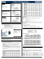
PP07 PP11, PP30, 4÷20mA pressure
transducers:
Sporlan
5 SER 1.5-20
6
Set parameter tPP = 420.
7
Connect:
Brown wire (+) to terminal 19;
White wire (-) to terminal 20
8
9
10
PPR15 PPR30 Ratiometric transducers
(0.5÷4.5Vdc)
Set parameter tPP = 5U
11
Connect:
Brown wire (+) to terminal 18;
White wire (in) to terminal 20;
Green wire (gnd) to terminal 21
12
13
14
Connect to terminals 13-14
CONFIGURABLE DIGITAL INPUT CONNECTION
The superheat regulation is performed only when the cooling digital input is enabled.
It’s possible to enable the SH regulation via:
Digital input 1, free voltage contact:
Use the terminals (14-15), set the parameter i1F = CCL, its polarity it’s set by par. i1P.
-
0
159
12
5
200
bP
FUL
0
319
16
5
200
bP
FUL
0
250
12
5
200
bP
FUL
0
638
16
5
200
bP
FUL
0
638
16
5
200
bP
FUL
0
638
16
5
200
bP
FUL
5
75
50
10
500
bP
FUL
10
160
75
25
500
bP
FUL
10
260
80
50
500
bP
FUL
uP
HAF
4
33
0
0
50
Liability Limitation
All the pre-sets have been done according to the documentation available when the XEV22D has been
released, see below reference:
Danfoss:
DKRCC.PD.VD1.C6.02 / 520H8021 @ Danfoss A/S (AC-MCI / sw), 2014-07
Sporlan:
92008 / Bulletin 100-20
RACE Catalogue 100-20-3 EDEV-2/UK - 02/2013
Emerson
FC-TD/ EX4-8 July 2008
In any case for each valve the only reference is given by the manual released by the manufacture
together with the valve.
Dixell can’t be considered responsible for any change made by the manufacturer and reported on the
manufacturer manual.
Temperature probe:
Set parameter
ttE = NTC: (NTC 10K) or
ttE = Pt1: (Pt1000) or
ttE = CtC: (NTC-US 10K)
4.6
Sporlan
SEI 30
Sporlan
SER(I)
G,J,K
Sporlan
SEI 50
Sporlan
SEH(I) 100
Sporlan
SEH(I) 175
Emerson
EX4-EX5EX6
Emerson
EX7
Emerson
EX8 500
Emerson
EX3
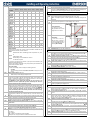
4.8.2 Manual setting of valve
To set the valve manually, act the according to the following procedure:
a.
Set tEP=0
b.
Then set following parameters: LSt, USt, Sr, CPP, CHd according to the valve manual
Digital input 2 (8-9), main voltage contact
Use the terminals (8-9), set the parameter i2F = CCL, its polarity it’s set by par. i1P
4.9
Usually the digital input is connected to a thermostat or an activation contact
VALVE CONNECTION
4.9.1
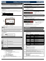
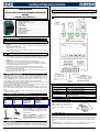
TERMINALS FOR VALVE CONNECTION
T= Thermostat ( or activation contact)
V= Stepper valve (mono or bipolar)
P1= Temperature sensor (PT1000 o
NTC or NTC-US)
P2= Pressure transducer 4..20mA or
ratiometric (0-5Vdc).
4 WIRES VALVES (BIPOLAR)
4.7
Connection
numbering
4
2
3
1
SUPPLY CONNECTION
Power supply: XEV22D is powered at 24Vac/dc.
Use Class 2 transformer at list 20VA as the TF20D
Connect transformer to terminals 11-12.
1.
2.
3.
Connection
numbering
4
2
3
1
5 – Common
VALVE CONFIGURATION
4.8.1
BEFORE CONNETTING THE VALVE
ALWAYS CONNECT OR DISCONNET THE VALVE WHEN THE CONTROLLER IS NOT
POWERED
CONFIGURE THE VALVE ON THE XEV22D BEFORE CONNECTING THE VALVE
Danfoss
1 ETS-25/50
2
3
4
Danfoss
ETS-100
Danfoss
ETS250/400
Sporlan
SEI 0.5-11
4.10
7
262
10
10
300
bP
FUL
10
353
10
10
300
bP
FUL
11
381
10
10
300
bP
FUL
0
159
16
5
200
bP
FUL
EMERSON
EX3
BLUE
BLACK
BROWN
WHITE
GRAY
SPORLAN
SAGINOMIYA
ORANGE
RED
YELLOW
BLACK
GRAY
ORANGE
RED
YELLOW
BLACK
GRAY
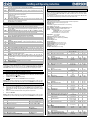
ABSOLUTE MAXIMUM POWER
XEV22D is able to drive a wide range of stepper valves, in the following table are indicated the
maximum values of current that the actuator can supply to the stepper wiring. The Dixell transformer to
use is the TF20D.
NOTE: the electrical power absorption of the valve can be unrelated to refrigeration power that valve
has. Before using the actuator, please read the technical manual of the valve supplied by the
manufacturer and check the maximum current used to drive the valve in order to verify that they are
lower than those indicated below.
LSt
uSt
CPP
CHd
Sr
tEu
HSF
(steps*10) (steps*10) (mA*10) (mA*10) (step/s) (bip/unip) (Half/full)
1592025990 XEV22D GB r1.5 14.11.2014.docx
DANFOSS
ETS
BLACK
WHITE
RED
GREEN
AFTER MAKING THE CONNECTION, PLEASE SWITCH OFF AND ON THE XEV CONTROLLER IN
ORDER TO BE SURE OF THE RIGHT POSITIONING OF THE VALVE.
BEFORE CONNECTING the valve, to avoid possible problems, configure the driver by making
the right changes on the parameters.
The max distance between an XM controller and a valve must not exceed 10 m. To avoid any
problems, use only shielded cables with section greater than or equal to 0.325 mm² (AWG22).
Select the kind of motor (tEU parameter) and check if the valve is present in tEP parameter
table reported here below.
tEP
BLUE
BROWN
BLACK
WHITE
SPORLAN
SEI-SEH
WHITE
BLACK
RED
GREEN
5-6 WIRES VALVES (UNIPOLAR)
VALVE
TYPE
4.8
ALCO EX
XEV22D
BIPOLAR VALVES
(4 wires)
Maximum Current 0.9A
UNIPOLAR VALVES
(5-6 wires)
Maximum Current 0.33A
2/6