1
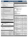
tEP Predefined valve selection: (0 to 14) MODEL Danfoss 1 ETS-25/50 2 3 4 5 6 7 8 9 10 11 12 13 14 Danfoss ETS-100 Danfoss ETS250/400 Sporlan SEI 0.5-11 Sporlan SER 1.5-20 Sporlan SEI 30 Sporlan SER(I) G,J,K Sporlan SEI 50 Sporlan SEH(I) 100 Sporlan SEH(I) 175 Emerson EX4-EX5EX6 Emerson EX7 Emerson EX8 500 Emerson EX3 MnF LSt uSt CPP CHd Sr tEu HSF (steps*10) (steps*10) (mA*10) (mA*10) (step/s) (bip/unip) (Half/full) 7 262 10 10 300 bP FUL 10 353 10 10 300 bP FUL 11 381 10 10 300 bP FUL 0 159 16 5 200 bP FUL 0 159 12 5 200 bP FUL 0 319 16 5 200 bP FUL 0 250 12 5 200 bP FUL 0 638 16 5 200 bP FUL 0 638 16 5 200 bP FUL 0 638 16 5 200 bP FUL 5 75 50 10 500 bP FUL 10 160 75 25 500 bP FUL 10 260 80 50 500 bP FUL uP HAF FoP PI PARAMETERS (trained staff) AMS Atu 4 33 0 0 50 LSt USt ESt Sr CPP CHd oPE SFd dty Proportional band: (0.1 to 50.0°C; 1 to 90°F) PI proportional band. A value bigger than 5°C is advised. rS Band Offset: (-12.0 to 12.0°C; -21 to 21°F) PI band offset. It permits to move the proportional band of the PI. With rS=0 the band is between [SEt to SEt+Pb]. inC dFc Integration time: (0 to 255s) PI integration time. Derivative time (0 to 255s) PID derivative time. PROBE PARAMETERS tPP LPP PA4 P20 oPr ttE otE Manual valve setting To set the valve manually, act the according to the following procedure: a. Set tEP=0 b. Then set following parameters: LSt, USt, Sr, CPP, CHd according to the valve manual Kind of motor movement: (HAF; FUL) HAF = half step. Use this setting for the unipolar valve. FUL = full step. Use this setting for the bipolar valve. Minimum number of steps: (0 to USt (*10)) it permits to select the minimum number of steps. At this number of steps the valve should be closed. So it’s necessary the reading of manufacturer datasheet to set correctly this parameter. It’s the minimum number of steps to stay in advised range of functioning. !!!!! WARNING !!!!! after changing this parameter the valve will have to be reinitialized. The device performs this procedure automatically and restarts its normal functioning when the programming mode ends. Maximum number of steps: (LSt to 800 (*10)) it permits to select the maximum number of steps. At this number of steps the valve should be completely opened. Read the datasheet provided by manufacturer of the valve to set correctly this parameter. It’s the maximum number of steps to stay in advised range of functioning. !!!!! WARNING !!!!! after changing this parameter the valve will have to be reinitialized. The device performs this procedure automatically and restarts its normal functioning when the programming mode ends. Extra step in closing phase: (0 to 255 (*10)) it sets the number of extra steps the controller performs, when the valve is closed at start up, to force the closure of the valve. Step rate: (10 to 600 step/sec) it is the maximum speed to change step without losing precision (=losing steps). It’s advised to stay under the maximum speed. Current per phase (only bipolar valves): (0 to 100 (*10mA)) it is the maximum current per phase used to drive valve. It’s used only with bipolar valves. Holding current per phase (only bipolar valves): (0 to 100 (*10mA)) it is the current per phase when the valve is stopped for more than 4 minutes. It’s used only with bipolar valves. Start opening Percentage: (0 to 100%) opening valve percentage when start function is active and during post defrost phase. This phase duration is SFd time. Start Function duration: (0.0 to 42min 00s, res. 10s) it sets start function duration and post-defrost duration. During this phase the alarms are not enabled. Pilot duty: (2-10dec/sec) To reach the final position the valve moves for Ton sec and stops for Tof sec, where Ton and Tof are defined as in the following:. Ton= dty/10s Toff= (1-dty/10)s Note: with dty=10 the Pilot duty function is disabled. With bipolar valve, during the Toff time the maintenance current is used. 1592025990 XEV22D GB r1.5 14.11.2014.docx Self self adaptive SH regulation enabling: parameter enables the self adaptive regulation of the superheat no = standard regulation using the PID parameters (Pb, rS, inC, dFC) yES = self-adaptive regulation, controller regulates SH automatically, setting the PID parameter Minimum STABLE superheat search (No; yES) This parameter enables the search of the minimum stable superheat. The lowest admitted value is LSH+2°C Pb Liability Limitation All the pre-sets have been done according to the documentation available when the XEV22D has been released, see below reference: Danfoss: DKRCC.PD.VD1.C6.02 / 520H8021 @ Danfoss A/S (AC-MCI / sw), 201407 Sporlan: 92008 / Bulletin 100-20 RACE Catalogue 100-20-3 EDEV-2/UK - 02/2013 Emerson FC-TD/ EX4-8 July 2008 In any case for each valve the only reference is given by the manual released by the manufacture together with the valve. Dixell can’t be considered responsible for any change made by the manufacturer and reported on the manufacturer manual. HFS Maximum opening percentage at normal Functioning: (0 to 100%) during regulation it sets the maximum valve opening percentage. Forced Opening percentage: (0 to 100; nU) if FoP=nU valve works with regulation algorithm. If FoP is different from nU the valve stays at FoP opening percentage. This function could be useful during plant starting or during service operations. Type of Pressure transducer: (420; 5V; LAn) it sets type of pressure transducer to use. 420 = 4 to 20mA pressure transducer; 5V = 0 to 5V ratiometric transducer; LAn = the pressure signal comes from another XEV module. Enable pressure probe sending in LAN: (n; Y) if LPP=Y the value of pressure read by device is sent in LAN. Only one device of the LAN can have LPP=Y. Probe value at 4mA or at 0V: (-1.0 to P20 bar; -14 to P20 psi) pressure value measured by probe at 4mA or at 0V (related to PrM parameter). Probe value at 20mA or at 5V: (PA4 to 50.0 bar; PA4 to 725 psi) pressure value measured by probe at 20mA or at 5V (related to PrM parameter). Pressure probe calibration: -12.0 to 12.0 bar; -174 to 174 psi. Type of temperature probe: (PtM; ntC) it allows to set the kind of probe used by the instrument: PtM = PT1000 probe, ntC = NTC-US probe. Temperature probe calibration: -12.0 to 12.0°C; -21 to 21°F. DIGITAL INPUTS i1P i1F d1d i2P i2F d2d Digital Input 1 (Free of voltage) digital input polarity: (cL, oP) CL = activated when closed; oP = activated when opened. Digital Input 1 (Free of voltage) digital input function: (CCL, rL) CCL = cooling call; rL = digital input activates relay. Digital Input 1 (Free of voltage) activation delay: (0 to 255 min) this activation delay is used only if digital input is configured as rL. Digital Input 2 (High voltage) digital input polarity: (CL, oP) CL = activated when closed; oP = activated when opened. Digital Input 2 (High voltage) digital input function: (CCL, rL) CCL = cooling call; rL = digital input activates relay. Digital Input 2 (High voltage) activation delay: (0 to 255 min) this activation delay is used only if digital input is configured as rL. ALARM dAo tdA LPL MoP LoP PHY dML MSH XEV22D Alarm delay after restarting regulation: (0.0 to 42min 00s, res. 10s) time between digital input activation (configured as CCL) and alarm signalling. The LSH alarm is always signalled also during this time. Type of alarm signalled by relay: (ALL, SH, PrE, di) ALL = all alarm; SH = superheat alarm; PrE = pressure alarm; di = activation only when digital input configured as rL is active. Lower Pressure Limit for superheat regulation: (PA4 to P20 bar; PA4 to P20 psi) when suction pressure comes down to LPL, the regulation is performed with a LPL fixed value for pressure. When suction pressure comes back to LPL, the normal pressure value is used (related to PrM parameter). Maximum Operating Pressure threshold: (LoP to P20bar; LoP to P20 psi) if suction pressure exceeds maximum operating pressure value, the instrument signals this situation with an alarm LED (related to PrM parameter). Lowest Operating Pressure: (PA4 to MoP bar; PA4 to MoP psi) if the suction pressure comes down to this value, a low pressure alarm will be signalled with an alarm LED (related to PrM parameter). Pressure alarm Hysteresis: (0.1 to 5.0 bar, 1 to 72 psi) pressure hysteresis to disable alarm signalling. Delta MoP-LoP: (0 to 100%) when a MoP alarm occurs valve will close of the dML percentage every one second until MoP alarm is active. When LoP occurs, valve will open of the dML percentage every one second until LoP alarm is active. Maximum SuperHeat alarm: (LSH to 80.0°C; LSH to 144°F) when superheat exceeds this value, an high superheat alarm will be signalled after interval SHd. 4/6