1
LightPulse LP850 Fibre Channel PCI Host Adapter Manuals
Page 1 of 10
Prerequisites:
l
l
l
One open 32-bit or 64-bit PCI bus slot with a 3.3 VDC or 5.0 VDC signaling interface
Maximum PCI bus clock rate of 33 MHz
Media and connectors (user supplied; view supported media types.)
Follow these procedures to assemble and install the host adapter. Click procedures for
details. When finished, click "Return to top of page" to return to this summary.
1. Record reference numbers. Write down the host adapter's IEEE address and serial
number.
2. Install the host adapter board. Insert the host adapter board into a PCI slot on the
computer's motherboard.
3. Attach media. Connect fiber optic or copper duplex cabling to the host adapter.
4. Apply power. Apply power to the computer and observe the LED display.
After the host adapter is installed, install device drivers or run a DOS diagnostic program to
check host adapter functions or update firmware.
Record reference numbers
Each host adapter is shipped with a unique address identifier called the IEEE address. The
Fibre Channel industry uses a World Wide Name (WWN) derived from the IEEE address,
and this number is need for arbitrated loop connectivity. The serial number is used when
communicating with Emulex. Both numbers are clearly marked on the board. We
recommend that you record these numbers before installation.
Return to top of page.
Install the host adapter board
1.
2.
3.
4.
Turn off and unplug the computer.
Remove the computer case.
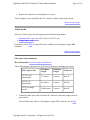
Remove the blank panel from an empty 32 or 64-bit PCI bus slot.
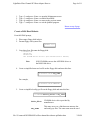
Insert host adapter board into the empty 32 or 64-bit PCI bus slot. Press firmly until
seated.
5. Secure the host adapter's mounting bracket to the case with the panel screw.
Copyright Emulex Corporation - All rights reserved, 1999
LightPulse LP850 Fibre Channel PCI Host Adapter Manuals
Page 2 of 10
6. Replace the computer case and tighten case screws.
The host adapter is now installed in the PC. Continue with the attach media section.
Return to top of page.
Attach media
Select one of these types of media supported by the Emulex host adapter:
l
l
Multimode fiber optic cable (50/125 µm or 62.5/125 µm)
Copper duplex cable
If necessary, use an MIA to connect fiber optic cabling to a host adapter's copper DB9
connector.
Return to top of page.
Fiber optic cable (multimode)
More Information: View fiber optic specifications.
These cables support a data rate of 1.0625 Gb/s for short wave and long wave lasers.
Fiber Optic Cable
Maximum
Length
Minimum
Length
Connector
62.5/125 µ m
(multimode)
175 meters
2 meters
Dual SC
50/125 µ m
(multimode)
500 meters
2 meters
Dual SC
9/125 µm (single
mode)
10,000 meters
2 meters
Dual SC
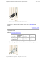
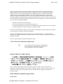
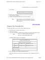
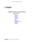
1. Connect the fiber optic cable to the dual SC connector on the host adapter board as
shown below.
To attach fiber optic cable to a host adapter's copper DB9 connector, use an MIA.
Copyright Emulex Corporation - All rights reserved, 1999
LightPulse LP850 Fibre Channel PCI Host Adapter Manuals
Page 3 of 10
2. Connect other end of cable to Fibre Channel device.
After the media is connected to the host adapter, you are ready to apply power to the
computer.
Return to top of page.
Copper duplex cable
TechNote: View copper specifications.
Cable Type
Maximum
Length
Data Rate
Connector
Dual Twinax
or Quad Axial
30 meters
1.0625 Gb/s
DB9
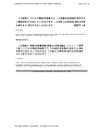
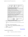
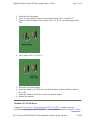
1. Connect the copper duplex cable to the DB9 connector on the host adapter board as
shown below.
Copyright Emulex Corporation - All rights reserved, 1999
LightPulse LP850 Fibre Channel PCI Host Adapter Manuals
Page 4 of 10
2. Connect other end of cable to Fibre Channel device.
After the media is connected to the host adapter, you are ready to apply power to the
computer.
Return to top of page.
Apply Power
1.
2.
3.
4.
Verify the host adapter is securely installed in the computer.
Verify correct media is attached.
Plug in and turn on computer.
Observe LEDs for Power On Self Test (POST) results.
Return to top of page.
Power On Self Test and LEDs
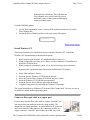
Green and yellow display lights (LEDs) can be seen through openings in the host adapter's
mounting bracket. Green indicates power and yellow signifies port activity.
This chart shows normal LED indications. For other LED patterns, refer to the detailed LED
chart.
Green LED
Yellow
LED
State
OFF
flashing
POST processing in progress
(irregular)
ON
blink
normal - active - link up
blink
OFF
normal - link down or not yet started
Host adapter installation is complete. At this point, you should install a driver or run the
DOS diagnostic utility. Return to index to choose.
Return to top of page.
Copyright Emulex Corporation - All rights reserved, 1999
LightPulse LP850 Fibre Channel PCI Host Adapter Manuals
Page 5 of 10
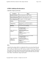
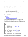
LP850 Additional Information
LP850 Host Adapter Specifications
Parameter
Range
Hardware Interface
20 pin connector for GBIC models
Physical Dimensions
Short PCI form factor 6.88" x 4.20"
Power Requirements
11 watts @ + 5.0 VDC (typical)
Airflow
100 lfm minimum
Temperature
Operating: 32° to 113°F (0° to 45°C)
Storage: 14° to 131°F (-10° to 55°C)
Humidity
5% to 95% non-condensing
Agency Approvals for
LP850-D1
UL recognized to UL1950
CUR recognized to CSA22.2, No. 950
TUV certified to EN60950
FCC Rules, Part 15, Class A
Industry Canada, ICES-003, Class A
EMC Directive 89/336/EEC (CE Mark)
EN55022, Class A
EN50082-1
Australian EMC Framework (C-Tick Mark)
AS/NZS 3548:1994, Class A
VCCI, Class A.
Agency Approvals for
LP850-N1/T1
and LP850-F1
Class 1 Laser Product per DHHS 21CFR (J) & EN60825
UL recognized to UL1950
CUR recognized to CSA22.2, No.950
TUV certified to EN60950
FCC Rules, Part 15, Class B
Industry Canada, ICES-003, Class B
EMC Directive 89/336/EEC (CE Mark)
EN55022, Class B
EN50082-1
Australian EMC Framework (C-Tick Mark)
AS/NZS 3548:1994, Class B
VCCI, Class B
MIA
A Media Interface Adapter (MIA) is an adapter that allows you to convert from fibre optic
cable to copper. The adapter has two signal interfaces: an optical interface (SC connector)
and a serial interface (DB9 connector). By connecting an MIA to a copper DB9 connector on
a host adapter, a non-Open Fiber Control (non-OFC) optical link is provided. The Emulex
host adapter with a copper interface is designed to support an MIA that conforms with the
Fibre Channel - Media Interface Adapter specification.
Copyright Emulex Corporation - All rights reserved, 1999
LightPulse LP850 Fibre Channel PCI Host Adapter Manuals
Page 6 of 10
An MIA is user supplied.
Note
To attach an MIA,
1. Connect the MIA DB9 connector to the host adapter copper
DB9 connector.
2. Tighten screws carefully - do not over tighten.
3. Connect the SC connector of the fiber optic cabling to the
optical SC port of the MIA.
For more information on MIA specifications and operating instructions, consult the MIA
manufacturer’s documentation.
Supported media types
l
l
l
Multimode fiber optic cable (50/125 µ m or 62.5/125 µ m) with dual SC connectors,
used with short wave lasers
Copper duplex cabling with DB9 connectors (also called DE9)
Media Interface Adapter (MIA) used to convert from fiber optic to copper, if required
(user supplied)
Host Adapter LEDs
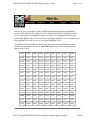
POST conditions and results are summarized in this table.
Green LED
Yellow
LED
State
OFF
OFF
wake-up failure (dead board)
OFF
ON
POST failure (dead board)
OFF
slow
blink (1
Hz)
wake-up failure
OFF
fast blink
(4 Hz)
failure in POST
OFF
flashing
POST processing in progress
(irregular)
Copyright Emulex Corporation - All rights reserved, 1999
LightPulse LP850 Fibre Channel PCI Host Adapter Manuals
ON
OFF
failure while functioning
ON
ON
failure while functioning
ON
slow
blink (1
Hz)
normal - inactive
ON
flashing
normal - active
(irregular)
ON
fast blink
(4 Hz)
normal - busy
slow blink
OFF
normal - link down or not yet started
slow blink
slow
blink (1
Hz)
off-line for download
slow blink
fast blink
(4 Hz)
restricted off-line mode (waiting for restart)
Page 7 of 10
FCC and Regulatory Notices
Class 1 Information Label
CLASS 1 LASER PRODUCT
LASER KLASSE 1
LUOKAN 1 LASERLAITE
APPAREIL A` LASER DE CLASSE 1
TO IEC 825-1 (1993) + CENELEC HD 482 S1
The above statement applies to products marketed in the European Union.
FCC and VCCI
Model LP850-D1 (Copper Model)
This device complies with Part 15 of the FCC Rules. Operation is subject to the following two conditions: (1)
This device may not cause harmful interference, and (2) this device must accept any interference received,
including interference that may cause undesired operation.
Copyright Emulex Corporation - All rights reserved, 1999
LightPulse LP850 Fibre Channel PCI Host Adapter Manuals
Page 8 of 10
This equipment has been tested and found to comply with the limits for a Class A digital device, pursuant to
part 15 of the FCC Rules. These limits are designed to provide reasonable protection against harmful
interference when the equipment is operated in a commercial environment. This equipment generates, uses, and
can radiate radio frequency energy and, if not installed and used in accordance with the instruction manual,
may cause harmful interference to radio communications. Operation of this equipment in a residential area is
likely to cause harmful interference in which case the user will be required to correct the interference at his own
expense. Shielded cables must be used between this equipment and attached peripheral devices. The reader is
cautioned that changes or modifications made to the equipment not expressly approved by Emulex could void
the user’s authority to operate this equipment.
The above statement applies to products marketed in the USA
This class A digital apparatus meets all requirements of the Canadian Interference - Causing Equipment
Regulations. Cet Appareil numerique de la classe A respecte toutes les exigences du reglement sur le material
brouilleur du Canada.
The above statement applies to products marketed in Canada.
FCC Compliance Information Statement; Models LP850-T1/N1 (GBIC Models)
FCC Compliance Information Statement; Model LP850-F1 (1 X 9)
This device complies with Part 15 of the FCC Rules. Operation is subject to the following two conditions: (1)
This device may not cause harmful interference, and (2) this device must accept any interference received,
including interference that may cause undesired operation.
Responsible Party: Paul Folino, President & CEO, Emulex Corporation, 3535 Harbor Blvd., Costa Mesa, CA
92626, USA, (714) 662-5600
Copyright Emulex Corporation - All rights reserved, 1999
LightPulse LP850 Fibre Channel PCI Host Adapter Manuals
Page 9 of 10
Note: This equipment has been tested and found to comply with the limits for a Class B digital device,
pursuant to Part 15 of the FCC Rules. These limits are designed to provide reasonable protection against
harmful interference in a residential installation. This equipment generates, uses and can radiate radio
frequency energy and, if not installed and used in accordance with the instructions, may cause harmful
interference to radio communications. However, there is no guarantee that interference will not occur in a
particular installation. If this equipment does cause harmful interference to radio or television reception, which
can be determined by turning the equipment off and on, the user is encouraged to try to correct the interference
by one or more of the following measures:
l
l
l
l
Reorient or relocate the receiving antenna.
Increase the separation between the equipment and receiver.
Connect the equipment into an outlet on a circuit different from that to which the receiver is connected.
Consult the dealer or an experienced radio/TV technician for help.
The reader is cautioned that any changes or modifications to the equipment not expressly approved by Emulex
could void the user’s authority to operate this equipment.
This class B digital apparatus meets all requirements of the Canadian Interference - Causing Equipment
Regulations. Cet Appareil numerique de la classe B respecte toutes les exigences du reglement sur le material
brouilleur du Canada.
The above statement applies to products marketed in Canada.
VCCI Notices and Translations (Japan Only)
Note
VCCI regulations provide that changes or modifications
not expressly approved by Emulex Corporation could
void your authority to operate this equipment.
Models LP850-T1/N1 (GBIC Models)
This is a Class B product based on the standard of the Voluntary Control Council for Interference by
Information Technology Equipment (VCCI). If this equipment is used near a radio or television receiver in a
domestic environment, it may cause radio interference. Install and use the equipment according to the
instruction manual.
Model LP850-D1 (Embedded Copper Model)
Product Label
Copyright Emulex Corporation - All rights reserved, 1999
LightPulse LP850 Fibre Channel PCI Host Adapter Manuals
Page 10 of 10
Translation:
This is a Class A product. In a domestic environment this product may cause radio interference in which case
the user may be required to take adequate measures. VCCI—A
Manual Notice
Translation:
This is a Class A product based on the standard of the Voluntary Control Council for Interference by
Information Technology Equipment (VCCI). If this equipment is used in a domestic environment, radio
disturbance may arise. When such trouble occurs, the user may be required to take corrective actions.
Copyright Emulex Corporation - All rights reserved - 1998
Copyright Emulex Corporation - All rights reserved, 1999
Page 1 of 4
Laser Safety Notice
This laser safety information contains certification and product information covering laser products known as
optical Gigabaud Link Modules (GLMs), Gigabit Interface Converters (GBICs) and 1x9 transceivers sold as
accessories to or incorporated in Emulex LightPulse host adapters. The GLM, GBIC and 1x9 transceiver are the
primary cable connection mechanisms for any optical port on the host adapter and hub. This data is not intended
to be a replacement for any safety regulations and standards; relevant safety documents should always be
consulted if necessary. Contact Emulex Corporation with any questions or concerns about laser safety.
Certification and Classification
Labeling Requirements
Product Information
Usage Restrictions
System Level Certification
Certification and Classification
LP6000 and LP7000/E PCI host adapters may contain a laser product known as an optical Gigabaud Link
Module (GLM). The optical GLM is attached to the host adapter using an 80-pin connector and extends through
the mounting bracket. In turn, the host adapter can be inserted into any host system's PCI slot.
The LH5000 hub may contain a laser product known as a Gigabit Interface Connector (GBIC). The GBIC
provides the physical connector to the optical cable. The GBIC can be inserted into any pluggable hub port.
The LP8000 and LP850 PCI host adapter may contain a laser product known as a Gigabit Interface Converter
(GBIC) or an embedded 1x9 transceiver. The GBIC and or 1x9 transceiver provide the physical connection to
the optical cable, and its SC-style connector extends through the mounting bracket. In turn, the host adapter can
be inserted into any host system’s PCI slot.
In the United States, all optical GLMs, GBICs and 1x9 transceivers sold by Emulex are certified as Class 1 laser
products that conform to the requirements contained in the Department of Health and Human Services (DHHS)
regulation 21 CFR subchapter J. The certification is indicated by a label located on the optical GLM, GBIC or
1x9.
In Europe, all optical GLMs, GBICs and 1x9 transceivers sold by Emulex are certified as Class 1 laser
component assemblies that conform to the requirements contained in the International Electrotechnical
Commission (IEC) standard 825-1 (1993) and CENELEC (European Committee for Electrotechnical
Standardization) standard EN60825-1 (1994). GLMs, GBICs and 1x9 transceivers are certified by a recognized
European testing agency and have appropriate markings on the assembly. The DHHS conformity label and
European conformity mark will not be visible externally once the optical GLM, GBIC or 1x9 is connected to or
inserted in the host adapter and the adapter is installed into a system.
Return to top of page.
Labeling Requirements
No caution or danger labels are required for use of the GLM, GBIC or 1x9 transceiver since they are Class 1
laser component assembly. In the U.S., the only laser safety label required is the DHHS certification label that
already appears on the GLM, GBIC and 1x9 transceiver. In Europe, the IEC825-1/EN60825-1 standards require
that the system-level product has a Class 1 information label permanently attached and clearly visible whenever
Copyright Emulex Corporation - All rights reserved, 1999
Page 2 of 4
access to the GLM, GBIC or 1x9 transceiver optical port is possible. Each Class 1 product shall have affixed an
explanatory label bearing the words:
Alternatively, at the discretion of the manufacturer, the same statement may be included in user information. If a
label is used, an example of the IEC Class 1 information label that is suitable for most European countries is
shown below. The label consists of black printing on a white background. Languages represented on this label
are English, German, Finnish and French, and they represent the minimum set for acceptance of a Class 1
product in most European countries. Refer to IEC 825-1 (1993) for recommended label and border dimensions.
Return to top of page.
Product Information
GLM
GBIC
1 x 9 Transceiver
GLM
The optical GLM is a single port communications card. Each communication port consists of a
transmitter and receiver optical subassembly. The transmitter subassembly contains a semiconductor laser
diode of gallium aluminum arsenide (GaAlAs). This material emits in the wavelength range of 770 to 860
nanometers for shortwave and 1270 to 1355 nanometers for long wave, and are commonly referred to as
short wavelength (SW) or long wavelength (LW) lasers. The discrete laser diodes are classified as Class
3B laser products. Once they are incorporated into the GLM, the product’s automatic power control
maintains the average power launched into a fiber at a value below the Class 1 limit.
Note
OFC GLMs are found only on the LP6000. Any
reference to OFC or non-OFC products apples only
to the LP6000, and not to the LP7000/E, LP8000 or
LP850.
For OFC GLMs (Open Fiber Control) the optical fiber link between two GLM ports is continuously
monitored by the open fiber link detection and laser safety control system (OFC). In the event of a break
anywhere in the path, this control system prevents laser emissions from exceeding Class 1 levels. For
Copyright Emulex Corporation - All rights reserved, 1999
Page 3 of 4
non-OFC links, the optical power from the laser transmitter is controlled and maintained at a lower power
level. The power emitted from either an open fiber or open laser transmitter is guaranteed to be below the
Class 1 limit. Class 1 laser products are not considered hazardous. No user maintenance, service
operations or adjustments can be performed on any GLM accessory.
GBIC
The optical GBIC is an integrated duplex data link for bi-directional communications over multimode or
single mode optical fiber. Each GBIC consists of a transmitter and receiver optical subassembly. The
transmitter subassembly contains a semiconductor laser emitting in the wavelength range of 770 to 860
nanometers for shortwave length GBICs and 1270 to 1355 nanometers for long wavelength GBICs. For
non-OFC links, the optical power from the laser transmitter is controlled and maintained at a lower power
level. The power emitted from either an open fiber or open laser transmitter is guaranteed to be below the
Class 1 limit. Class 1 laser products are not considered hazardous. No user maintenance, service
operations or adjustments can be performed the GBIC.
1x9 Transceiver
The 1x9 transceivers is an integrated duplex data link for bi-directional communications over multimode
fiber. Each 1x9 consists of a transmitter and receiver optical subassembly. The transmitter subassembly
contains a semiconductor laser emitting in the wavelength range of 770 to 860 nanometers for shortwave
1x9s. For non-OFC links, the optical power from the laser transmitter is controlled and maintained at a
lower power level. The power emitted from either an open fiber or open laser transmitter is guaranteed to
be below the Class 1 limit. Class 1 laser products are not considered hazardous. No user maintenance,
service operations or adjustments can be performed the 1x9 transceiver.
Return to top of page.
Usage Restrictions
Failure to comply with these usage restrictions may result in incorrect operation of the system and could possible
lead to points of access that may emit laser radiation levels above the Class 1 limits established in the U. S. by
the DHHS and within Europe by IEC 825-1/EN60825-1.
GLM
GBIC
1 x 9 Transceiver
GLM
The GLM is designed and certified for applications using point-to-point optical fiber links only. Use of
the product with multiple input or multiple output optical links (for example, star couplers) is prohibited
since it is incompatible with the GLM’s certification.
The GLM will not allow normal data transmission on the optical link unless it is connected to another
similar GLM or compatible laser product. For OFC GLMs, another manufacturer’s laser product is not
considered compatible unless it contains the open fiber link detection and laser safety control system
(OFC) and is properly certified as a Class 1 laser product. Similarly, for non-OFC GLMs, a compatible
laser device must be non-OFC.
Any system level product that incorporates the GLM must provide power supply protection that
guarantees a voltage of 6.0 volts or less at the GLM. The functional power supply range of the GLM
Copyright Emulex Corporation - All rights reserved, 1999
Page 4 of 4
product is specified as 4.75 to 5.25 volts typically. Operation outside of this range may degrade the
performance and lifetime of the GLM. The GLM will remain operational with laser emissions below
Class 1 limits provided the power supply level at the adapter remains at or below 6.0 volts. If the power
supply level rises above 6.0 volts, the GLM cannot be guaranteed to operate correctly and could result in
laser emissions that may exceed Class 1 limits.
GBIC
Short wavelength and long wavelength GBICs allow normal data transmission on the optical link when
they are connected to another compatible laser product. Short wavelength and long wavelength GBICs
sold by Emulex as accessories are non-OFC devices. For non-OFC links, a compatible laser device must
be non-OFC and certified as a Class 1 laser product.
1 x 9 Transceiver
Short wavelength 1x9 transceivers allow normal data transmission on the optical link when they are
connected to another compatible laser product. Short wavelength 1x9s embedded in Emulex host adapters
are non-OFC. For non-OFC links, a compatible laser device must be non-OFC and certified as a Class 1
laser product.
Return to top of page.
System Level Certification
All GLMs and GBICs sold as accessories by Emulex or host adapters containing embedded 1x9 transceivers are
certified as Class 1 laser products within the U.S. and Class 1 laser component assemblies outside of the U.S.
Manufacturers of products properly incorporating the GLM, GBIC or 1x9 transceiver do not need to recertify
their product for laser safety. The procedure for full system certification is therefore identical to that used for any
other electronic system. When applying for system level certification to electronic standards such as IEC950, the
regulatory engineers may want to see the DHHS and European conformity labeling on the GLM, GBIC or 1x9
transceiver, and the system level documentation and labeling. Copies of the certificate of conformity for any
GLM, GBIC or 1x9 transceiver sold by Emulex can be obtained upon request from Emulex Corporation, Costa
Mesa.
Copyright Emulex Corporation - All rights reserved, 1999
LightPulse Fibre Channel PCI Host Adapter Drivers
Page 1 of 2
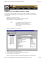
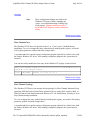
Windows NT 4.0 SCSI Mini Port Driver
Prerequisites:
Verify these minimum operating environment and software requirements:
l
l
l
l
Windows NT 4.0 server, with Service Pack 3
Emulex SCSI mini-port driver for Windows NT
Installed LP3000, LP6000, LP7000/E, LP8000, or LP850 host adapter
Fibre Channel drives connected to the host adapter using fiber optic or copper duplex
media (user supplied)
Follow this procedure to install the Emulex SCSI mini port driver for Windows NT 4.0.
Click procedure for details. When finished, click "Return to top of page" to return to this
summary.
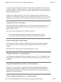
1. Install Windows NT SCSI Mini Port Driver. The driver files are located on the
diskette included with your product.
Once the driver is installed, you can use the host adapter in the Windows NT environment,
or manage the host adapter using the Mini Port Utility (see the Management Guide.
TechNote: See the How to... Guide to enable simultaneous networking and storage. To
perform additional configuration changes see the how to guide or consult your
Windows NT documentation.
Install Windows NT SCSI Mini Port Driver
From the Windows NT desktop,
1.
2.
3.
4.
5.
6.
7.
8.
9.
10.
Select Start, Settings, and Control Panel.
Double click the SCSI Adapters icon.
Select Drivers tab.
Click Add.
Click Have Disk.
Enter the path to the driver files and click OK.
Select the Driver and click OK to install necessary files.
Click Yes to restart the computer.
Select Start, Settings, and Control Panel.
Double click the SCSI Adapters icon.
file://G:\emuweb\WWWROOT\ts\fibre-channel\docs\drivers pdf\5ntscsim.htm
3/28/99
LightPulse Fibre Channel PCI Host Adapter Drivers
Page 2 of 2
11. Select Drivers tab.
Verify the Emulex SCSI mini-port driver is present and started.
12. Select Devices tab.
Verify that the host adapter is present.
13. Click the "+" sign to expand the adapter listing.
Verify the connected disk drive is listed.
Once the driver is installed, you can use the host adapter in the Windows NT
environment, or manage the host adapter using the Mini Port Utility (see the
Management Guide.
To perform additional configuration changes see the How to... Guide or consult your
Windows NT documentation.
Copyright Emulex Corporation - All rights reserved - 1999
file://G:\emuweb\WWWROOT\ts\fibre-channel\docs\drivers pdf\5ntscsim.htm
3/28/99
LightPulse Fibre Channel PCI Host Adapter Management
Page 1 of 1
DOS Management
Run diagnostics to verify the host adapter's installation and view host adapter
properties or upgrade the host adapter's firmware.
Windows NT 4.0 SCSI Port Driver Utility
Use the Emulex Configuration Utility to configure LP6000, LP7000/E and LP8000
host adapters. Perform LUN mapping, SCSI device mapping, upgrade host adapter
firmware, and modify driver parameters in the Windows NT registry.
Windows NT 4.0 SCSI Mini Port Driver Utility
View LP6000, LP7000/E and LP8000 host adapter parameters, download PCI
configuration files (CFL), modify driver parameters in the Windows NT registry, and
upgrade host adapter firmware.
Boot BIOS
Boot BIOS works with the existing system BIOS on Intel Pentium PCI motherboards.
Boot BIOS allows you to designate a fibre channel drive as the boot drive, change the
arbitrated loop physical address (ALPA), change the link timers, select topologies
(arbitrated loop or fabric), enable or disable individual devices.
Copyright Emulex Corporation - All rights reserved - 1999
file://E:\emuweb\WWWROOT\ts\fibre-channel\docs\manage pdf\index.htm
3/24/99
LightPulse Fibre Channel PCI Host Adapter Management
Page 1 of 5
DOS Diagnostic Utility
The lp6dutil is a DOS-based program that enables a user to test the host adapter board and to
upload firmware. This program is intended for use in a stand-alone environment. You can
designate a single computer as a test station and test up to four host adapter boards at the
same time. The lp6dutil program tests a variety of host adapter boards (for example,
LP6000, LP7000/E, and LP8000). Running this program while the host adapter is connected
to an arbitrated loop is not recommended.
Prerequisites:
l
l
l
Installed Emulex host adapter
DOS 6.x or higher (program may not run in the DOS shell under Windows on all
systems.
Loopback connector for expanded testing (user supplied)
Follow these procedures to perform hardware diagnostic testing of an Emulex host adapter.
Click procedure for details. When finished, click "Return to top of page" to return to this
summary.
1. Verify operating conditions. Do not run the lp6dutil program with a memory manager
or under a DOS shell in Windows on all systems.
2. Install lp6dutil. Copy the software to your hard drive.
3. Start lp6dutil. Type the command to run the program or customize the command with
command options.
4. Examine the diagnostic main menu to display available tests and options.
Verify operating conditions
Ensure that you run lp6dutil under these conditions::
l
l
Stop all memory manager programs like Expanded Memory Manager (EMM386).
Run in DOS, not in a DOS shell under Windows.
Install lp6dutil software to hard drive
1. Make a directory on your hard drive.
2. Insert diagnostic diskette in disk drive or download from
Copyright Emulex Corporation - All rights reserved - 1999
LightPulse Fibre Channel PCI Host Adapter Management
2. Insert diagnostic diskette in disk drive or download from
ftp.emulex.com/pub/fibre/lp6xxx/lp6dutil.
3. Copy files to your hard drive.
Start lp6dutil
At the DOS prompt, enter lp6dutil with or without command options.
c:\>lp6dutil {o=outfilename} {i=infilename} {/d} {/nr} {d=xxxx}
Option
Description
infilename
Script input file that is read and executed by the program.
outfilename
Creates a file of keystrokes that is stored for later use (for example, as
an input file).
d
Enables prompt for remapping the host adapter’s memory
requirements.
nr
When the utility starts, the host adapter is not restarted.
xxxx
Alternate device ID. When the utility starts, it searches for the host
adapter at the device ID entered here.
Preliminary testing
The diagnostic program performs the following preliminary analysis of the host adapter
boards before displaying the Main menu:
l
l
l
l
l
l
l
Looks for installed PCI host adapters and display up to four.
Performs preliminary testing on all installed host adapters, including:
SLIM memory test
BIU register test
BIU configuration registers test.
Reports pass or fail status messages.
Resets the host adapters.
Checks POST (Power On Self Test) status of host adapters.
Reports revision levels of diagnostic and functional firmware.
Displays the resources of each host adapter.
If no host adapter is found, the program will exit. Error messages are displayed when
failures occur.
Copyright Emulex Corporation - All rights reserved - 1999
Page 2 of 5
LightPulse Fibre Channel PCI Host Adapter Management
Page 3 of 5
failures occur.
Diagnostic main menu
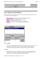
After the lp6dutil goes through its start-up procedure, the Main menu displays and handles
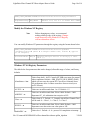
user requests. To display a previous menu, you must type 0. Displayed values are
hexadecimal.
If lp6dutil finds two or more host adapters in the system, you will be prompted to select
which host adapter(s) is to be tested.
These choices are available from the Main menu.
Test Host Adapters - This option runs host-based internal and external loopback tests.
Modify Test Options - You can enable or disable up to 7 different tests, depending
upon the cards installed (BIU-1 or BIU-2). Specify number of retries, and actions to
take if error occurs.
Restart Host Adapters - Resets the host adapter under test.
Input/Output - This option opens or closes input and output files.
Maintenance - This option is used to update firmware or non-volatile parameters in
FLASH ROM, and can display program images stored in memory.
Show Host Adapters Info - This displays various configuration and status data that can
be used by Tech Support to help troubleshoot problems.
Quit - Finish all testing and exit the lp6dutil program.
Test Host Adapters
1. Select this option to run these host-based internal and external loopback tests on the
host adapter.
Internal BIU PCI loopback and other loopback tests are run automatically.
2. Choose 0 (No) if you do not have an external loopback connector.
External loopback tests are disabled by default (0 = No (default); 1 = Yes).
Modify Test Options
Copyright Emulex Corporation - All rights reserved - 1999
LightPulse Fibre Channel PCI Host Adapter Management
1. Select the desired test: PCI loopback, Internal loopback, External Loopback through
the GLM, or all three.
These test options are available for BIU-2 cards: BIU2 Tx and Rx DMA, BIU2 GP
DMA, and BIU2 concurrent DMA.
To perform the external loop back test, you must connect a loopback connector.
2. Configure the SRAM test by entering the number of sequences (or concurrent
sequences) and the sequence byte length.
3. Select number of passes (default is 0x50; 0 = infinity).
4. Select action to take upon encountering errors (0 = stop (default), 1 = repeat, 2 =
ignore).
Restart Host Adapters
Select this option to reset the host adapter. When restart occurs, lp6dutil performs POST
testing on the adapter and its reloads functional firmware.
Input/Output
Select this option to open or close input and output files. An input file is interpreted and
executed by the lp6dutil program. The output file contains a log of all messages.
Maintenance
Use this option to update the firmware or non-volatile parameters in the Flash ROM. This
option also displays program images (load list) stored in the host adapter’s memory. You
must reboot the host adapter for the new firmware to take effect.
Show Host Adapter Info
Select this option to display this host adapter data:
BIU PCI Configuration Parameters
Host Adapter Info and Status
Adapter Revisions
Display Configuration data
Service Parameters
Status/Counters Info
Link Status
Link Attention
Copyright Emulex Corporation - All rights reserved - 1999
Page 4 of 5
LightPulse Fibre Channel PCI Host Adapter Management
Page 5 of 5
Quit
Select this option to exit the lp6dutil program. A warning message occurs if errors were
encountered during the session.
Upgrade firmware
Prerequisites:
l
l
l
l
DOS 6.x or higher (program may not run in the DOS shell under Windows on all
systems.
DOS diagnostic utility program installed
Firmware image file upgrade (available from Emulex ftp server at
ftp.emulex.com/pub/fibre.
No memory manager programs like Expanded Memory Manager (EMM386) currently
running.
Upgrade procedure
1. Boot up computer in DOS.
2. Enter this command to start the lp6dutil program.
c:\>lp6dutil
3.
4.
5.
6.
7.
8.
9.
Type 5 Maintenance on the Main menu.
Type 1 to Upgrade Firmware.
Enter new image file name and path to upgrade file.
Type 1 to upgrade now.
Type CR to reset the host adapter.
Type 0 until the Main menu reappears.
Type 7 to Quit.
Copyright Emulex Corporation - All rights reserved - 1999
Copyright Emulex Corporation - All rights reserved - 1999
Page 1
Windows NT 4.0 SCSI Port Driver Utility
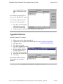
The Emulex Configuration Utility (elxcfg.exe) is installed automatically as an executable during
the SCSI port driver installation. A shortcut to the utility is located on the Start Menu under
Programs. When launched, the configuration utility will probe the registry. Adapters defined in
the registry are listed in the Available Adapters list box. This list displays the adapter type, bus
number, slot location and firmware revision.
Prerequisites
l
l
Installed host adapter with connected device
Installed SCSI port driver
The utility is explained under the following sections.
l
l
l
l
Host Adapter Function Buttons
Adapter Controls
Adapter Timer Settings
SCSI Target list box
file://E:\emuweb\WWWROOT\ts\fibre-channel\docs\manage pdf\7pt_util.htm
LightPulse Fibre Channel PCI Host Adapter Management
Page 2 of 7
Host Adapter Function Buttons
These functions can be viewed and or executed as long as the adapter is installed. Execution of
these functions take effect immediately.
l
l
l
l
l
Remove Adapter - Removes previously installed adapter information.
Firmware - Download new firmware to the host adapter.
Memory - View the host adapter memory.
Reset Bus - Emulate a SCSI bus reset using the host adapter.
Network - Select and view the host adapter networking parameters.
Remove Adapter
The Remove Adapter button is used to delete a host adapter's entry from the registry. This
can only occur after the physical removal of the host adapter. When the adapter is
physically present in the bus, the Remove Adapter button is grayed out (disabled).
Firmware
The Firmware button is used to download a new firmware image into the host adapter's
flash ROM. Firmware images can be downloaded from the Emulex FTP site. The
firmware will be verified, downloaded, and the adapter restarted.
Copyright Emulex Corporation - All rights reserved - 1999
LightPulse Fibre Channel PCI Host Adapter Management
Page 3 of 7
firmware will be verified, downloaded, and the adapter restarted.
Memory
The Memory button brings up the Memory Dump window. Enter the desired starting
address in the Memory Offset edit box, and the length in bytes of the memory to dump in
the Count edit box.
Click Reload to display contents in the memory dump window.
Reset Bus
The Reset Bus button will emulate a SCSI bus reset.
Network
Note
Network parameters are only valid if an IP driver or
Combo driver is installed.
The Network button brings up the Network Configuration window which allows you to set
the following parameters.
l
l
l
Networking - enable or disable networking.
Class - Select the class of service.
Class 2 permits frame transfers with an acknowledgment and Class 3 permits frame
transfers with out an acknowledgment.
MTU - enter the appropriate Maximum Transfer Unit in decimal format.
Return to top of page.
Adapter Controls
General host adapter configurations are located under Adapter Controls. Check or clear the
check box to enable or disable contols. All changes take effect after a server reboot.
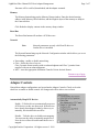
Automatically Map SCSI Devices
Enable – Tells the driver to automatically map new
SCSI devices as they are discovered. If the devices
have already been mapped, either by discovery or
manually, this checkbox has no effect.
Disable – Tells the driver to disable auto mapping.
You must use the utility to manually map devices.
New devices will not be usable until the device is
mapped.
Copyright Emulex Corporation - All rights reserved - 1999
LightPulse Fibre Channel PCI Host Adapter Management
Page 4 of 7
mapped.
Query name server for all N-Ports
Enable – Tells the driver to poll the name server for
all connected N-Ports.
Disable – The driver will ask for all registered SCSI
FCP devices.
Note
Emulex adapters register as a SCSI FCP device. If
the only devices on the fibre channel are Emulex
Adapters and storage devices, the same list of
devices will be returned for each of the two choices.
Point to Point
Enable – Causes the adapter to initialize in a point to point configuration. This control
should also be checked if connected to a fabric via an F-Port.
Disable – The adapter will use Loop Initialization to initialize the link.
Allow Multiple paths to SCSI Targets
Enable – Mapped SCSI devices are reported on each connected port.
Disable – Mapped SCSI devices are reported only on the first connected port.
Register for State Change
Enable – When a fabric is present, the driver will register with the fabric to receive
Registered State Change Notification (RSCN) ELS requests from the fabric.
Disable – The driver will not register with the fabric, even if the fabric is present.
Note
Disabling State Change Notification will disable the
automatic discovery of new devices. It will also
prevent the recovery when moving cables on a
switch connected to a storage device.
Use Report LUNs
Enable - For all SCSI devices, the driver will issue a Report LUNs SCSI command to
determine the LUNs present on the storage device. The target device is responsible for
reporting all present LUNs. If this option is enabled and the target device supports Report
Copyright Emulex Corporation - All rights reserved - 1999
LightPulse Fibre Channel PCI Host Adapter Management
Page 5 of 7
reporting all present LUNs. If this option is enabled and the target device supports Report
LUNs, then the Maximum number of LUNs is ignored for the target device.
Disable - If the target does not support the Report LUNs SCSI command or the option is
disabled, then the driver will poll each device for the present LUNs. The driver will start
with LUN 0 and proceed for each LUN up to the Maximum LUN value.
Use Name Server after RSCN
Enable - The driver will ignore the payload of the RSCN and query the name server for the
latest list of devices.
Disable - The driver relies on the data in the RSCN payload to update the list of devices.
Note
This option should be selected if using a switch with
FL ports or soft zoning (check your switch
manufacturers user guide). If neither FL ports or
soft zoning is being used, disable this option for
faster recovery after faults.
LUN Mapping
Enable - All LUNs behind all targets are mapped. Since Fibre Channel targets support a
LUN number 64 bits long and the port driver under NT only supports 8 bits, some sort of
mapping is required. Unmapped LUNs are not accessable by NT.
Disable - There is a one to one correspondence of Fibre Channel LUNs to NT LUNs.
In the case where LUN Mapping is not used, the Fibre Channel LUN is created as follows:
00xx00000000
where the xx is the NT LUN number.
Automatic LUN Mapping
Enable - LUNs are automatically mapped by the driver as they are discovered.
Note
Automatic mapping may cause LUN numbers to
"change". For example, the LUN indicated by the
SCSI Applet on the control panel may be different
from the actual LUN number on the device. The
mapping can be viewed by clicking on the LUN
Mapping button.
Disable - LUNs must be manually mapped.
Use SLI-1 mode
file://E:\emuweb\WWWROOT\ts\fibre-channel\docs\manage pdf\7pt_util.htm
3/24/99
LightPulse Fibre Channel PCI Host Adapter Management
Page 6 of 7
Enable –SLI-1 is used even if the adapter is capable of SLI-2.
Disable – The driver will use SLI-2.
Maximum Number of LUNs
This is the number of LUNs the driver will poll during device discovery. The minimum
value is 1, the maximum value is 255.
Maximum Queue Depth
The number of outstanding commands to a single LUN.
Return to top of page.
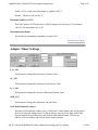
Adapter Timer Settings
E_D_TOV
This parameter changes the Error Detect Timeout Value,
AL_TOV
This parameter changes the Arbitrated Loop Timeout Value,
R_A_TOV
This parameter changes the Resource Allocation Timeout Value
ARB_TOV
This parameter changes the Arbitration Timeout Value.
Static Poll Destination Address
The Static Poll Destination Address lists a 24 bit Fibre Channel address that will be polled
for devices when the adapter boots. To add an address, enter the 6 hex digits of the Fibre
Channel address in the Address box and click the Add Address button. To delete an
address, select the address and click the Delete Address button.
file://E:\emuweb\WWWROOT\ts\fibre-channel\docs\manage pdf\7pt_util.htm
3/24/99
LightPulse Fibre Channel PCI Host Adapter Management
Page 7 of 7
Return to top of page.
SCSI Targets list box
The SCSI Targets list box shows the current SCSI ID to Fibre Channel World Wide Port name
mapping.
Add Mapping
Add mapping allows you to map available
and unmapped Fibre Channel devices to a
SCSI ID.
Modify
Allows you to modify a currently mapped
device.
Delete Mapping
Deletes the current mapping.
LUN Map
LUN map shows the LUN mapping for a
selected target.
Note
The LUN Map button will only be enabled if the
LUN Mapping check box is checked for the adapter.
Return to top of page.
Copyright Emulex Corporation - All rights reserved - 1999
file://E:\emuweb\WWWROOT\ts\fibre-channel\docs\manage pdf\7pt_util.htm
3/24/99
LightPulse Fibre Channel PCI Host Adapter Management
Page 1 of 6
Windows NT SCSI Mini Port Driver Utility
The host adapter utility (Lputilnt.exe) is an executable file on the diskette containing the
host adapter driver. Run the utility from the floppy or copy and run it from your local hard
drive. Requires:
l
l
l
Windows NT version 4.0 or greater
Installed LP6000, LP7000/E, LP8000, or LP850 host adapter
Installed Windows NT SCSI Mini Port Driver
Note
The LightPulse Utility/NT Requires that the
SCSI Mini-port driver be installed and
connected to at least one drive before it can
operate properly.
1. Double click Lputilnt.exe to start utility.
2. Select an adapter from the list on the left.
3. On the menu bar, click Adapter or pull down the Category list.
4. Select an option to view parameters.
There are eight options available, each displaying a different group of host adapter
file://E:\emuweb\WWWROOT\ts\fibre-channel\docs\manage pdf\5nts_1ut.htm
3/24/99
LightPulse Fibre Channel PCI Host Adapter Management
Page 2 of 6
There are eight options available, each displaying a different group of host adapter
parameters:
Adapter Revision Levels - View information about the chipset and firmware revision
levels of the selected adapter.
Firmware Maintenance - View detailed information about the firmware in the Flash
ROM of the selected host adapter. The user can also:
¡
¡
¡
Upgrade host adapter firmware
Manage existing firmware
Enable or Disable the adapter's Boot BIOS
Loop Map - View a list of the members of the selected host adapter's loop map.
PCI Registers - View the values of the PCI configuration registers for the selected
adapter.
Configuration Data - View information about the data in each of the configuration
regions in the Flash ROM of the selected host adapter. The user can also:
¡
Download PCI configuration files (CFL)
Driver Parameters - View information about device driver parameters that are
maintained in the Windows/NT registry. The user can also:
¡
Modify driver parameters in the Windows NT registry
Link Statistics - View statistics about the arbitrated loop of the selected host adapter.
Status and Counters - View status and counters for bytes, frames, sequences,
exchanges, etc.
Return to top of page.
Firmware Maintenance
From the LightPulse Utility/NT main window,
1. Select the desired host adapter.
2. Expand the Category list and select Firmware Maintenance.
This display provides detailed information about the firmware in the Flash
ROM of the selected host adapter. The radio buttons determine how data
is displayed.
l
Flash ROM List shows all firmware images in the selected
adapter’s flash ROM.
file://E:\emuweb\WWWROOT\ts\fibre-channel\docs\manage pdf\5nts_1ut.htm
3/24/99
LightPulse Fibre Channel PCI Host Adapter Management
l
l
Page 3 of 6
adapter’s flash ROM.
Flash ROM Map displays these same images, along with unused flash ROM space.
RAM Map displays the firmware images currently loaded in the selected adapters
SRAM.
Firmware images that are referenced in the host adapter’s wake-up
parameters are denoted with a W in the leftmost column of the display.
From the Firmware Maintenance window, you can:
l
l
l
Upgrade host adapter firmware
Delete or activate existing firmware
Enable or disable the adapter's Boot BIOS
Upgrade Host Adapter Firmware
1. Obtain a copy of the desired upgrade file.
Upgrade files are available on the Emulex ftp server at ftp.emulex.com/pub/fibre/.
2.
3.
4.
5.
6.
7.
Start the utility.
Select the desired host adapter
Expand the Category list and select Firmware Maintenance.
Click Download.
Locate the new upgrade file.
Click Open.
The new software is transferred to the host adapter.
8. Expand the Category list and select Adapter Revision Levels.
9. Verify the new firmware revision is shown.
Delete or Activate Firmware Image
Deleting a firmware image may be necessary in order to provide storage for a subsequent
download. When two images of the same type, but different revision exist in the host
adapter's Flash ROM, you may select which image is active. Only one image of a particular
type can be active at a time. The active image is preceded by a W in the list.
From the LightPulse Utility/NT main window,
1.
2.
3.
4.
Select the desired host adapter.
Expand the Category list and select Firmware Maintenance.
Select a firmware image.
Click Delete to remove the image file or Activate to activate the image file.
Return to top of page.
file://E:\emuweb\WWWROOT\ts\fibre-channel\docs\manage pdf\5nts_1ut.htm
3/24/99
LightPulse Fibre Channel PCI Host Adapter Management
Page 4 of 6
Return to top of page.
Enable or Disable Boot BIOS
Boot BIOS is used to designate a Fibre Channel drive as the boot drive. To enable a Fibre
Channel drive as the boot drive, first enable Boot BIOS using this procedure and then refer
to the Boot BIOS section.
From the LightPulse Utility/NT main window,
1. Select the desired host adapter.
2. Expand the Category list and select Firmware Maintenance.
3. Select the Boot BIOS Firmware image.
If Boot BIOS Firmware is not listed, you will need to download a
Boot BIOS image.
4. Click Enable.
The Enable button toggles to Disable when Boot BIOS is enabled.
Download PCI configuration files (CFL)
This display provides information about the data in each of the configuration regions in the
Flash ROM of the selected host adapter. The user selects a region in the drop-down Region
list and the data contained in that region is displayed. Regions 5, 6 and 7 allow the user to
download PCI configuration data files to the selected region.
file://E:\emuweb\WWWROOT\ts\fibre-channel\docs\manage pdf\5nts_1ut.htm
3/24/99
LightPulse Fibre Channel PCI Host Adapter Management
Page 5 of 6
From the LightPulse Utility/NT main window,
1.
2.
3.
4.
5.
6.
Select the desired host adapter.
Expand the Category list and select Configuration Data.
Expand the Region list and select region 5, 6, or 7.
Click Download button.
Enter the path to the PCI configuration data file (*.cfl).
Click Open.
File is downloaded into the selected region.
Modify driver parameters in the Windows NT registry
This display provides information about device driver parameters that are maintained in the
Windows/NT registry, and allows those values to be modified. All available device driver
parameters are listed in the data display, along with the current, minimum, maximum, and
default values. Parameters that have their value specified in the system registry are denoted
with either a G or an L in the leftmost column of the display. The G indicates that the value
is set in the global registry entry, which applies to all adapters that do not have a local
registry entry. The L indicates that the value is set in a registry entry specific to the selected
adapter, which overrides the value settings in the global entry. A column labeled Dynamic
indicates if a parameter change takes effect immediatly. Values for this parameter are yes,
restart, and reboot.
Modifying Driver Parameters
From the LightPulse Utility/NT main window,
1.
2.
3.
4.
5.
Select the desired host adapter.
Expand the Category list and select Driver Parameters.
Double click on a parameter name.
Enter desired value in the New Value field.
Select Permanent or Global checkbox.
Select Permanent to cause the new value to be written to the system registry. If Permanent is
not selected, the parameter will revert to its default value when the driver is reset.
Select Global to change the global registry entry. Otherwise, the change is made to the
adapter-specific registry entry.
Update Device Driver
Device drivers are updated periodically and can be obtained from the Emulex website at
ftp.emulex.com/pub/fibre/. In the Windows NT environment, you should remove the
existing driver before installing a new driver. Follow the steps below to remove an existing
driver and then refer to the installation section to install a new driver.
file://E:\emuweb\WWWROOT\ts\fibre-channel\docs\manage pdf\5nts_1ut.htm
3/24/99
LightPulse Fibre Channel PCI Host Adapter Management
Page 6 of 6
From the Windows NT desktop,
1.
2.
3.
4.
5.
6.
7.
Click Start, select Settings, and Control Panel.
Double click the SCSI Adapters icon.
Select Drivers tab.
Click Remove, and Yes to confirm.
Click OK.
Reboot the computer to restart Windows NT.
Install new driver.
Copyright Emulex Corporation - All rights reserved - 1999
file://E:\emuweb\WWWROOT\ts\fibre-channel\docs\manage pdf\5nts_1ut.htm
3/24/99
LightPulse Fibre Channel PCI Host Adapter Management
Page 1 of 4
Boot BIOS Utility
Requirements:
l
l
l
l
Intel Pentium computer system, with system BIOS copyrighted 1995 or later
MS-DOS 6.0 or higher
Installed LP3000, LP6000, LP7000/E or LP8000 host adapter
Connected Fibre Channel drive or disk array
Boot BIOS does the following:
l
l
l
l
l
Supports up to 8 LightPulse Fibre Channel host adapters per computer.
Supports multi-initiators on different systems, connected by hubs.
Supports multiple disk arrays and LUNs (up to 8 LUNs per ALPA).
Detects up to 99 devices per adapter
Displays a maximum of 16 devices during the boot process.
This page provides a detailed description of each menu choice on the Boot BIOS Utility
menu. Default options are acceptable for most installation. If a menu is marked as an
"Advanced Option", novice users should accept the defaults.
The Main Menu choices are described below. Select a link for additional descriptions, or
click "Return to top of page" to return to this summary.
Change BIOS boot device/display all devices
Change default ALPA on this adapter
Enable or disable BIOS on this adapter
Change FC Link Timer
Change Extended Link Service Timer
Enable or disable individual devices
Change PLOGI retry timer
Topology selections
Fabric D_ID and WWPN selection
Change BIOS Boot Device/Display All Devices
This option applies to an arbitrated loop (FC-AL) topology only. It shows all drives attached
to the selected host adapter. The adapter is not the boot device, but a drive attached to the
host adapter can be designated as the boot device. The first device in the list is the boot
device. By default, the lowest arbitrated loop physical address (ALPA or AL_PA) of the
device on the first adapter will be the boot disk.
file://E:\emuweb\WWWROOT\ts\fibre-channel\docs\manage pdf\6bbios2.htm
3/24/99
LightPulse Fibre Channel PCI Host Adapter Management
Page 2 of 4
device on the first adapter will be the boot disk.
To specify a Fibre Channel drive as the boot device, enter a two digit number (01, 02, etc.)
to specify which drive will be the boot device. (After specifying a device as the boot device,
go to menu option 6 to verify that device is enabled). The Boot device at the top of the menu
changes to reflect this entry.
Each device is displayed by ALPA, Select ID, LUN number and drive information. Use
<PageDn> to scroll through a long list of drives to find the desired boot device. Only 16 are
shown on the screen each time, but a maximum of 99 devices per adapter can be displayed.
Change default ALPA of this adapter
This option applies only to arbitrated loop (FC-AL). Use this option to change the ALPA
(Arbitrated Loop Physical Address) of the selected adapter. The default ALPA for the
adapter BIOS is 01 (hex).
The ALPA could be changed if these conditions are present:
l
l
The computer with the installed host adapter is moved to another location.
The System Administrator designates a change for administrative purposes.
Enable or Disable BIOS on This Adapter
Use this option to enable or disable boot BIOS on the selected host adapter. If enabled, a
device connected to the host adapter can be designated as the boot device. Default is
disabled.
Boot BIOS can be enabled on more than one host adapter at a time.
Change FC Link Timer (+ Advanced Option +)
Use this option to configure the Link up wait timer. Choices are 5, 10, 15 (default), 20, and
30 seconds. Link up wait time is the time that the host adapter will wait for a link up to be
established.
Changed Extended Link Service Timer (+ Advanced Option +)
Link services are used for log in, sequence and exchange management, and connection
maintenance. Use this option to configure the wait timer for the Extended Link Service
(ELS) command. Examples are PLOGI (port log in) or Prli (process log in). Choices are 4
(default), 10, 20 and 90 seconds.
Enable or Disable Individual Devices (+ Advanced Option +)
file://E:\emuweb\WWWROOT\ts\fibre-channel\docs\manage pdf\6bbios2.htm
3/24/99
LightPulse Fibre Channel PCI Host Adapter Management
Page 3 of 4
Enable or Disable Individual Devices (+ Advanced Option +)
This option applies only to arbitrated loop (FC-AL). Default is enabled for each device.
Each device can be enabled or disabled by the user. The maximum number of devices
(including LUNs) that can be displayed in the device menu is 99 per adapter.
If a change is made to the boot device in the Change BIOS Boot Device/Display All
Adapters menu, the user must check this menu to verify that the new boot device is enabled.
This menu option must be updated to reflect any hardware configuration changes.
Change PLOGI Retry Timer (+ Advanced Option +)
This menu is used to set the interval for the PLOGI (port log in) Retry Timer. This option is
especially useful for Tachyon-based RAID arrays. Under very rare occasion, a Tachyonbased RAID array will reset itself and the port will go off line temporarily in the loop. When
the port comes to life, the PLOGI retry interval scans the loop to discover this device.
The time it takes for one PLOGI to scan the whole loop (if 126 ALPA are on the loop) is
shown below:
l
l
l
50 msec will take 5 to 6 seconds.
100 msec will take 12 seconds.
200 msec will take 22 seconds.
The default is 0 (no retry); other options are 50, 100 and 200 milliseconds.
Topology Selections (+ Advanced Option +)
Use this option to select the topology for the host adapter. Choose 1 for arbitrated loop (FCAL) and 2 for fabric point to point. The default is FC-AL
Fabric D_ID and WWPN section (+ Advanced Option +)
This applies to fabric point to point topology only.
Fabric destination identifier (D_ID) indicates the address identifier of the N_Port.
A list of devices will be displayed by a Name Server Inquiry, which contains a list of all port
identifiers. By default, the first successful D_ID returned from a Name Server Inquiry will
be the boot device.
A dialog box appears with these choices.
D_ID and WWPN. D_ID and WWPN are checked to see if they are also in the BIOS
region 8 area. If they are the same, boot occurs.
file://E:\emuweb\WWWROOT\ts\fibre-channel\docs\manage pdf\6bbios2.htm
3/24/99
LightPulse Fibre Channel PCI Host Adapter Management
Page 4 of 4
region 8 area. If they are the same, boot occurs.
WWPN only. Name Server Inquiry is issued to locate the D_ID of this WWPN. If
found, a boot can occur.
D_ID only. PLOGI is issued to this D_ID regardless WWPN.
Copyright Emulex Corporation - All rights reserved - 1999
file://E:\emuweb\WWWROOT\ts\fibre-channel\docs\manage pdf\6bbios2.htm
3/24/99
LightPulse Fibre Channel PCI Host Adapter How to...
Page 1 of 11
All Operating Systems
Boot from a fibre channel drive
Boot BIOS works with the existing system BIOS on Intel Pentium PCI
motherboards and allows a system to boot from a fibre channel drive.
Connect a fiber optic cable to a copper port
Use an MIA to convert media.
Upgrade the host adapter's driver
You must first remove the existing driver before installing a new driver.
Upgrade the host adapter's firmware
Using the DOS utility, save a new copy of the host adapter's firmware in its
flash ROM
Windows NT
Assign Windows NT ALPA
Permanently assign an ALPA (Arbitrated Loop Physical Address) to the host
adapter.
Use the Windows NT event viewer
The Windows NT SCSI driver verifies the success of the PCI Host adapter’s
Power On Self Test (POST). In case of a failure or suspected failure, an error
log entry is issued to the Windows NT System Event Logger (Viewer).
Enable simultaneous networking and storage over Windows NT
Install two host adapters in the same Windows NT computer and use one for
storage and one for networking.
file://G:\emuweb\WWWROOT\ts\fibre-channel\docs\howto pdf\index.htm
3/28/99
LightPulse Fibre Channel PCI Host Adapter How to...
Page 2 of 11
Enhance Windows NT SCSI driver performance
Advanced users only. Configure registry to enhance performance when using a
Windows NT SCSI driver.
Enhance Window NT IP driver performance
Modify class, topology or MTU values or the way Windows NT TCP/IP
services transmits Ethernet packets (802.3 SNAP) by changing registry values.
Perform LUN mapping
This procedure requires the use of the Emulex Configuration Utility. This
Utility is installed along with the Windows NT 4.0 SCSI Port driver.
Perform manual SCSI mapping
This procedure requires the use of the Emulex Configuration Utility. This
Utility is installed along with the Windows NT 4.0 SCSI Port driver.
Upgrade host adapter firmware using the Emulex Configuration Utility
This procedure requires the use of the Emulex Configuration Utility. This
Utility is installed along with the Windows NT 4.0 SCSI Port driver.
Designate a fibre channel drive as the boot drive
Boot BIOS is a set of x86 instructions in the host adapter Flash ROM that allows a user to
designate a Fibre Channel hard drive as the boot drive. Boot BIOS works with the existing
system BIOS on Intel Pentium PCI motherboards.
Note
The examples in this chapter use the Windows NT
4.x operating system.
Supported Host Adapters
LP6000, LP7000/E, LP8000, and LP850.
Requirements
l
l
l
Intel Pentium computer system, with system BIOS copyrighted 1995 or later
MS-DOS 6.0 or higher
Windows NT 4.x installation media
file://G:\emuweb\WWWROOT\ts\fibre-channel\docs\howto pdf\index.htm
3/28/99
LightPulse Fibre Channel PCI Host Adapter How to...
l
l
l
l
Page 3 of 11
Installed host adapter
Connected Fibre Channel drive or disk array
The Emulex SCSI mini-port driver
LP6dutil DOS Diagnostic, version 8.3 or higher
Defining a Fibre Channel Drive as the Boot Drive
The following is a summary of the procedures necessary to define a Fibre Channel disk drive
as the boot drive in Windows NT 4.x.
l
l
l
l
l
Enable Boot BIOS
Create a DOS boot disk
Designate a Fibre Channel boot drive
Format the Fibre Channel drive
Install Windows NT 4.x operating system
Return to top of page.
Enable Boot BIOS
Note
You can enable Boot BIOS using the Windows NT
LightPulseUtility/NT to enable Boot BIOS. See
page 5-7 or use the DOS utility as shown below.
1. Boot the system in DOS.
2. Insert lp6dutil diskette in drive A.
3. Type this command:
a:\>lp6dutil
The Main menu is displayed.
lp6dutil Main Menu
1 - Test Host Adapters
2 - Modify Test Options
3 - Restart Host Adapters
4 - Input/Output
5 - Maintenance
6 - Show Host Adapters Info
7 - Quit
From the lp6dutil Main menu,
file://G:\emuweb\WWWROOT\ts\fibre-channel\docs\howto pdf\index.htm
3/28/99
LightPulse Fibre Channel PCI Host Adapter How to...
1.
2.
3.
4.
Page 4 of 11
Type <5> and press <Enter> to open the Maintenance menu.
Type <3> and press <Enter> to enable Boot BIOS.
Type <0> and press <Enter> to return to the previous menu.
Type <7> and press <Enter> to exit the lp6dutil program.
Return to top of page.
Create a DOS Boot Diskette
From MS-DOS prompt,
1. Place empty floppy disk in drive.
2. Format floppy with system files.
format a:/s
3. Copy these four files onto the floppy disk.
format.com
fdisk.exe
mscdex.exe
The CD-ROM device driver (see manufacturer’s manual)
Note
SCSI CD-ROMs can use the ASPI DOS driver or
the DOSCAM driver.
4. Create a simplified autoexec.bat file on the floppy disk and enter this line:
a:\mscdex.exe/d:any_name
For example,
a:\mscdex.exe/d:OEMCD001
5. Create a simplified config.sys file on the floppy disk and enter this line:
a:\DEVICE=device_driver/d:any_name
device_driver
any_name
CD-ROM device driver provided by
manufacturer.
This name serves as a link between autoexec.bat
and config.sys files. The same name must be used
file://G:\emuweb\WWWROOT\ts\fibre-channel\docs\howto pdf\index.htm
3/28/99
LightPulse Fibre Channel PCI Host Adapter How to...
Page 5 of 11
in both the config.sys and autoexec.bat files.
For example,
a:\DEVICE=MTMCDAI.SYS/d:OEMCD001
6. Reboot system with floppy and verify your system boots properly.
7. Power down the computer.
8. Disable or disconnect the IDE hard drive from its controller.
Do not disconnect the IDE CD-ROM. The system
BIOS will always scan for IDE before scanning for
other interfaces.
Note
Return to top of page.
Designate a Fibre Channel Boot Drive
This procedure allows a user to select a Fibre Channel boot drive.
1. Insert the newly created boot disk in drive A.
2. Turn on the computer.
3. Press <F5> immediately when the message displays to go to the Emulex BIOS Utility.
Note
Press <F5> within 5 seconds of the displayed
message to invoke the Boot BIOS utility.
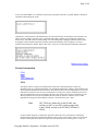
The Main window displays a list of adapters
Emulex LPxxx BIOS Utility
LightPulse Adapters in the System:
1.
ALPA: 18
PCI BUS #: 00
PCI DEVICE #: 10
2.
ALPA: 01
PCI BUS #: 00
PCI DEVICE #: 0E
Enter a Selection:
Enter <F7> to Exit:
4. Select the adapter by entering the appropriate number.
Any Fibre Channel drive attached to the host adapter can be designated as the boot
device.
file://G:\emuweb\WWWROOT\ts\fibre-channel\docs\howto pdf\index.htm
3/28/99
LightPulse Fibre Channel PCI Host Adapter How to...
Adapter
1:
ALPA: 18
Page 6 of 11
PCI BUS #: 00
PCI DEVICE #:
10
1.
Change BIOS Boot Device/Display All Devices.
2.
Change default ALPA of this Adapter.
3.
Enable or Disable BIOS on this Adapter.
4.
Change FC Link Timer (+ Advanced Option +)
5.
Changed Extended Link Service Timer (+ Advanced Option +)
6.
Enable or Disable Individual Devices (+ Advanced Option +)
7.
Change PLOGI Retry Timer (+ Advanced Option +)
8.
Topology Selections (+ Advanced Option +)
9.
Fabric Boot (+ Advanced Option +)
Enter a Selection:
Enter <F7> to Exit
<F6> to
Default
Values
<PageUp> to Previous
Menu
5. Type <1> and press <Enter> to display all devices.
6. Enter the two digit number (01, 02, etc.) to specify the boot device.
The Boot Device ALPA information at the top of the menu changes to reflect your
entry.
7. Press <PageUp> to return to the previous menu.
8. Type <3> and press <Enter> to enable Boot BIOS on the adapter.
9. Type <1> and press <Enter> to enable BIOS on the selected drive (if not already
enabled).
10. Press <F7> to exit Boot BIOS.
11. Select <Y> to reboot.
Return to top of page.
Format the Fibre Channel Drive
Caution
Ensure that the system IDE or SCSI hard drive is
file://G:\emuweb\WWWROOT\ts\fibre-channel\docs\howto pdf\index.htm
3/28/99
LightPulse Fibre Channel PCI Host Adapter How to...
Page 7 of 11
disabled before continuing. This will allow the
Fibre Channel drive to boot, and will prevent
accidental erasure of the system disk during the
format procedure below.
From the MS-DOS prompt,
1. Use the fdisk command to create a primary DOS partition (maximum size) on the
Fibre Channel disk.
2. Format the Fibre Channel hard drive with copy system files option.
a:\format c: /s
Return to top of page.
Install Windows NT
These steps summarize the installation script provided by Windows NT. Consult the
Windows NT documentation for detailed descriptions.
1. Boot computer with Windows NT installation disk #1 in drive A.
2. When prompted the first time, press <Enter> to allow Windows NT installation to
detect the CD-ROM drive.
3. When prompted a second time, press <S> to skip mass storage device detection.
Bypassing this step permits manual detection of additional SCSI adapters.
4.
5.
6.
7.
8.
9.
Select Other and press <Enter>.
Insert the Emulex Windows NT SCSI driver diskette.
Select the Emulex Fibre Channel SCSI driver and press <Enter>.
Insert the Windows NT CD-ROM when prompted.
Insert the Emulex driver diskette again when prompted.
Complete setup process by following the Windows NT prompts.
The system should boot up Windows NT from the Fibre Channel disk. You may now use it
as installed or install another operating system.
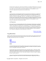
Connect a fiber optic cable to a copper port
If you want to connect fiber optic cable to a copper connector, you
can convert from one media to another by using an MIA. The
adapter has two signal interfaces: an optical interface SC connector
and a serial interface DB9 connector. By connecting an MIA to a
copper connector, a non-OFC optical link is provided. Any fixed
file://G:\emuweb\WWWROOT\ts\fibre-channel\docs\howto pdf\index.htm
3/28/99
LightPulse Fibre Channel PCI Host Adapter How to...
Page 8 of 11
copper duplex interface supports the Fibre Channel - Media
Interface Adapter specification.
Upgrade device driver
Note
It is important to remove the existing host
adapter driver before upgrading or reinstalling
a new driver.
Follow these procedures to upgrade or reinstall the device driver. Click procedure for
details. When finished, click "Return to top of page" to return to this summary.
1. Obtain driver - Obtain new driver from the Emulex ftp site at
ftp.emulex.com/pub/fibre.
2. Remove driver - Procedure differs for Windows NT 4.0, AIX, Solaris, or UnixWare.
3. Install new device driver
Obtain driver
Driver files are on the Emulex ftp server at ftp.emulex.com/pub/fibre.
Return to top of page.
Remove existing Windows NT 4.0 driver
The procedure is slightly different for the SCSI driver and IP driver. Refer to the proper
procedure.
Windows NT 4.0 SCSI driver
From the Windows NT desktop,
1.
2.
3.
4.
5.
6.
7.
Click Start, select Settings, Control Panel.
Double click Network icon.
Select Adapters tab.
Select Emulex PCI-Fibre Channel host adapter.
Click Remove and Yes to confirm.
Click Close.
Reboot the computer to restart Windows NT.
Return to top of page.
file://G:\emuweb\WWWROOT\ts\fibre-channel\docs\howto pdf\index.htm
3/28/99
LightPulse Fibre Channel PCI Host Adapter How to...
Page 9 of 11
Windows NT 4.0 IP driver
From the Windows NT desktop,
1.
2.
3.
4.
5.
6.
Click Start button, select Settings, and click Control Panel.
Double click the SCSI Adapters icon.
Select Drivers tab.
Click Remove, and Yes to confirm.
Click OK.
Reboot the computer to restart Windows NT.
Return to top of page.
Remove existing AIX driver
Select one of the previously released versions of the AIX SCSI/IP driver.
Prior Version Driver Name
1.0.0.0
df10e51a
2.0.0.0
lp6000
Versions Below 2.0.0.0
1. Login as root.
2. Open terminal window and type this command to uninstall old driver:
# installp -u devices.pci.df10e51a
3. Type this command to remove the network interface (fcnet):
# rmdev -dl fcnetn
where n is the network device driver (interface) number. A message should appear
showing device not found.
4. If the debugging program bosboot has been run previously, enter,
# bosboot -a -d /dev/ipldevice -D
file://G:\emuweb\WWWROOT\ts\fibre-channel\docs\howto pdf\index.htm
3/28/99
LightPulse Fibre Channel PCI Host Adapter How to...
Page 10 of 11
5. Reboot the system.
Return to top of page.
Versions 2.0.0.0 or Above
1. Login as root.
2. Open terminal window and type this command to uninstall old network drivers
(fchan).
#installp -u devices.pci.lp6000
3. If the debugging program bosboot has been run previously, enter,
# bosboot -a -d /dev/ipldevice -D
4. Reboot the system.
Return to top of page.
Remove existing Solaris device driver
1. Type this command to remove the driver package lpfc:
pkgrm lpfc
This command removes both the storage and networking drivers.
2. Type <y> when prompted to uninstall.
3. Reboot the system.
Return to top of page.
Remove existing UnixWare device driver
Perform these steps to remove a previously installed lp6fc device driver package:
1. Login as root user.
2. Enter this command to determine if a device driver is present.
file://G:\emuweb\WWWROOT\ts\fibre-channel\docs\howto pdf\index.htm
3/28/99
LightPulse Fibre Channel PCI Host Adapter How to...
Page 11 of 11
pkginfo -l lp6fc
3. Enter this command to remove the previously installed lp6fc device driver.
pkgrm lp6fc
4. Reboot the system.
Upgrade firmware
Prerequisites:
l
l
l
l
DOS 6.x or higher (program may not run in the DOS shell under Windows on all
systems.
DOS diagnostic utility - Download version 8.4
Firmware image file - Download latest versions from the Emulex ftp server at
ftp.emulex.com/pub/fibre
No memory manager programs like Expanded Memory Manager (EMM386) currently
running.
Upgrade procedure
1. Boot up computer in DOS.
2. Enter this command to start the lp6dutil program.
c:\>lp6dutil
3.
4.
5.
6.
7.
8.
9.
The main menu appears.
Type 5 to select Maintenance.
Type 1 to select Upgrade Firmware.
Enter Firmware Image file name including path.
Type 1 to proceed with the upgrade.
Type 1 when prompted to reboot the host adapter.
Type 0 until the Main menu reappears.
Type 7 to Quit.
Copyright Emulex Corporation - All rights reserved - 1999
file://G:\emuweb\WWWROOT\ts\fibre-channel\docs\howto pdf\index.htm
3/28/99
LightPulse Fibre Channel PCI Host Adapter How to Guide
Page 1 of 14
AL_PA Table
When a device is connected to a Fibre Channel arbitrated loop, the loop initialization
process (LIP) automatically assigns an ALPA (Arbitrated Loop Physical Address) to the
device. This number is assigned to the device as long as it is connected to the loop and
powered up. When the device is removed from the loop or turned off, as it is reconnected or
when another LIP occurs, the device is assigned a different ALPA.
The HardALPA=0xn command in the registry allows the user to permanently assign an
ALPA to the host adapter. However, only valid ALPAs may be used. The chart below
shows valid ALPAs.
0x01
0x02
0x04
0x08
0x0F
0x10
0x17
0x18
0x1B
0x1D
0x1E
0x1F
0x23
0x25
0x26
0x27
0x29
0x2A
0x2B
0x2C
0x2D
0x2E
0x31
0x32
0x33
0x34
0x35
0x36
0x39
0x3A
0x3C
0x43
0x45
0x46
0x47
0x49
0x4A
0x4B
0x4C
0x4D
0x4E
0x51
0x52
0x53
0x54
0x55
0x56
0x59
0x5A
0x5C
0x63
0x65
0x66
0x67
0x69
0x6A
0x6B
0x6C
0x6D
0x6E
0x71
0x72
0x73
0x74
0x75
0x76
0x79
0x7A
0x7C
0x80
0x81
0x82
0x84
0x88
0x8F
0x90
0x97
0x98
0x9B
0x9D
0x9E
0x9F
0xA3
0xA5
0xA6
0xA7
0xA9
0xAA
0xAB
0xAC
0xAD
0xAE
0xB1
0xB2
0xB3
0xB4
0xB5
0xB6
0xB9
0xBA
0xBC
0xC3
0xC5
0xC6
0xC7
0xC9
0xCA
0xCB
0xCC
0xCD
0xCE
0xD1
0xD2
0xD3
0xD4
0xD5
0xD6
0xD9
0xDA
0xDC
0xE0
0xE1
0xE2
0xE4
0xE8
0xEF
file://G:\emuweb\WWWROOT\ts\fibre-channel\docs\howto pdf\nt_alpa.htm
3/28/99
LightPulse Fibre Channel PCI Host Adapter How to Guide
Page 2 of 14
Windows NT Event Viewer
The Windows NT SCSI driver verifies the success of the PCI Host adapter’s Power On Self
Test (POST). In case of a failure or suspected failure, an error log entry is issued to the
Windows NT System Event Logger (Viewer).
From Main menu,
1.
2.
3.
4.
5.
Click Start, select Administrative Tools , Event Viewer.
Double-click any event with source name lp6nds35.
Change the data view from Bytes (default) to Words.
Examine entry at offset 0x10.
If low byte = En, match low byte with error found in SCSI Port Log Error table
Windows NT SCSI driver event log codes
l
l
l
Event Log
CmdStat values
Parm error values (valid only when cmdStat=0x3)
The Windows NT SCSI driver logs events and errors in the Windows NT event log. Serious
errors are always be logged, while informational events are only logged if the registry
parameter "LogErrors=1" is used. All Windows NT SCSI driver logged events are issued
with an Event ID of 11, Internal Adapter Error, but do not necessarily indicate an adapter
error occurred. Byte offset 0x10 of the event is the driver event code, while byte offset 0x110x13 contain event specific information.
0x10
Offset
Explanation
0x11-0x13 further information
0xD0
SNS_REQ
(XMIT_SEQ) failed
0x11= cmdStat, 12= Parm err
0xD1
SNS_RSP (RCV_SEQ)
failed
0x11= cmdStat, 12= Parm err
0xD3
RCV_ELS_REQ failed
0x11= cmdStat, 12= Parm err
0xD4
XMT_ELS_REQ failed
0x11= cmdStat, 12= Parm err
0xD5
Too many Targets
found (160+)
0x11 - 13 = D_ID that didn't fit
0xD6
SNS request time-out
0x11 - 13 no additional information
file://G:\emuweb\WWWROOT\ts\fibre-channel\docs\howto pdf\nt_alpa.htm
3/28/99
LightPulse Fibre Channel PCI Host Adapter How to Guide
Page 3 of 14
0xD7
Mailbox Interrupt Time0x11= Mailbox word 0
out
0xD8
TPRLO requested when
busy
0x11= local req. state, 12= discState, 13= Mailbox
word 0
0xD9
Link down time-out
occurred
0x11= local req. state, 12= discState, 13= Mailbox
word 0
0xE1
Error Interrupt occurred
Status register bytes 1-3 in event 11-13. E1 error
indicates an adapter hardware failure, return this
host adapter for repair
0xE2
Mailbox cmd Timeout
0x11= command
0xE3
Mailbox rsp err
0x11= command, 12-13 = mbxStatus
0xE4
Adapter not ready after
Init
Status register bytes 1-3 in event 11-13
0xE5
Requested Loop but
link=PT-PT
0xE6
Mailbox int. but cmd
not complete
0xE7
SRB already queued to
ring
0xE8
RESTART Failed
0xE9
PORT BYPASS (LPB)
received
0xEB
Unknown IOCB cmd
rsp
0xEC
Uncached Extension
alloc. error
0xED
Link down @boot time
(30 sec.)
0xEF
Too many Interrupts at
initial boot
0xF1
LinkUp err; LP6/7
Down, driver Up
0x11= MB cmd, 12-13 = mbxStatus
0x11= 15:8=cmd field
0x11= parameter field, 12=IOCB cmd
file://G:\emuweb\WWWROOT\ts\fibre-channel\docs\howto pdf\nt_alpa.htm
3/28/99
LightPulse Fibre Channel PCI Host Adapter How to Guide
Page 4 of 14
0xF2
LinkUp w/ Illegal or
corrupt RPI
0x11= parameter field, 12=IOCB cmd
0xF3
DeQueue ring>iotCmd.head
0x11= caller ID
0xF4
Adapter Reset
0x11= coded reason for reset:
bit 0=IOCB Requeue; bit 1=ReadLa retry
bit 2=InitLink retry; bit 3=RstBus retry
bit 4=Mailbox time-out
0xF5
FCP_IXXX_CR IOCB
rsp err
0x11= cmdStat, 12= Parm err, 13= ALPA
0xF6
FCP_IXXX_CX IOCB
rsp err
0x11= cmdStat, 12= Parm err, 13= ALPA
0xF7
Ring hd !=0 &&
pendingSrb!=NULL
0xF8
Invalid FCP_RSP
0xF9
Two consec. timeouts,
issue LIP
0xFA
START_IO error
0x11= ErrType, 12= SrbStat, 13= LinkUp
0xFB
ELS_REQ_CR IOCB
rsp err
0x11= cmdStat, 12= Parm err, 13= ALPA
0xFC
ELS_REQ_CX IOCB
rsp err
0x11= cmdStat, 12= Parm err, 13= ALPA
0xFE
FLOGI Failed
0x11= cmdStat, 12= Parm err
0xFF
SNS_PLOGI Failed
0x11= cmdStat, 12= Parm err
0x11= FcpCntrl, 12= ScsiStat, 13= Len
Return to top of page.
CmdStat values
file://G:\emuweb\WWWROOT\ts\fibre-channel\docs\howto pdf\nt_alpa.htm
3/28/99
LightPulse Fibre Channel PCI Host Adapter How to Guide
Page 5 of 14
IOSTAT_FCP_RSP_ERR
0x1
IOSTAT_REMOTE_STOP
0x2
Remote sent an ABTS
IOSTAT_LOCAL_REJECT
0x3
Parameter field contains additional info
IOSTAT_NPORT_RJT
0x4
IOSTAT_FABRIC_RJT
0x5
IOSTAT_NPORT_BSY
0x6
IOSTAT_FABRIC_BSY
0x7
IOSTAT_INTERMED_RSP
0x8
IOSTAT_LS_RJT
0x9
IOSTAT_BA_RJT
d0xA
Return to top of page.
Parm error values (valid only when cmdStat=0x3)
IOERR_SUCCESS
0x00
IOERR_MISSING_CONTINUE
0x01
IOERR_SEQUENCE_TIMEOUT
0x02
IOERR_INTERNAL_ERROR
0x03
IOERR_INVALID_RPI
0x04
IOERR_NO_XRI
0x05
IOERR_ILLEGAL_COMMAND
0x06
IOERR_XCHG_DROPPED
0x07
IOERR_ILLEGAL_FIELD
0x08
IOERR_BAD_CONTINUE
0x09
IOERR_TOO_MANY_BUFFERS
0x0A
file://G:\emuweb\WWWROOT\ts\fibre-channel\docs\howto pdf\nt_alpa.htm
3/28/99
LightPulse Fibre Channel PCI Host Adapter How to Guide
IOERR_RCV_BUFFER_WAITING
0x0B
IOERR_NO_CONNECTION
0x0C
IOERR_TX_DMA_FAILED
0x0D
IOERR_RX_DMA_FAILED
0x0E
IOERR_ILLEGAL_FRAME
0x0F
IOERR_EXTRA_DATA
0x10
IOERR_NO_RESOURCES
0x11
IOERR_RESERVED
0x12
IOERR_ILLEGAL_LENGTH
0x13
IOERR_UNSUPPORTED_FEATURE
0x14
IOERR_ABORT_IN_PROGRESS
0x15
IOERR_ABORT_REQUESTED
0x16
IOERR_RECEIVE_BUFFER_TIMEOUT
0x17
IOERR_LOOP_OPEN_FAILURE
0x18
IOERR_RING_RESET
0x19
IOERR_LINK_DOWN
0x1A
IOERR_CORRUPTED_DATA
0x1B
IOERR_CORRUPTED_RPI
0x1C
Page 6 of 14
Enable simultaneous networking and storage over Windows NT
By Windows NT default, if a Windows NT SCSI driver is installed, it will load first when
the computer boots, and use the host adapter's default or alternate device ID (View jumper
settings). The Windows NT IP driver loads later, and requires a separate device ID. This ID
is set through jumpers on the host adapter board. Jumper blocks JX1 and JX2 must be set to
enable the correct device ID.
This method requires two host adapters installed in the same computer. One adapter must be
an LP6000, LP7000/E or LP8000.
To run both drivers at the same time,
file://G:\emuweb\WWWROOT\ts\fibre-channel\docs\howto pdf\nt_alpa.htm
3/28/99
LightPulse Fibre Channel PCI Host Adapter How to Guide
Page 7 of 14
1. Install the first host adapter.
2. Leave one host adapter's jumpers in the default position: JX1:1-2 and JX2:2-3.
3. On the second host adapter, move jumper JX1:1-2 to JX1:2-3 to enable jumper block
JX2.
4. Move jumper JX2:2-3 to JX2:1-2.
5. Install the second host adapter.
6. Install the Windows NT SCSI driver on the host adapter with the default or alternate
device ID.
7. Install the Windows NT IP driver on the second host adapter.
8. Reboot the computer.
Windows NT 4.0 IP driver
Change the Class (class 3), Topology (loop) or MTU size (5DC) or enhance network
performance by forcing Windows NT TCP/IP to transmit Ethernet packets using 802.3 SNAP
file://G:\emuweb\WWWROOT\ts\fibre-channel\docs\howto pdf\nt_alpa.htm
3/28/99
LightPulse Fibre Channel PCI Host Adapter How to Guide
Page 8 of 14
encoding.
Note
These configuration changes are made to the
Windows NT registry. Before changing any
values, we recommend making a backup copy
of the registry. Changes made incorrectly to
the Windows NT Registry will have disastrous
effects.
Return to top of page.
Fibre Channel Class
The Windows NT IP driver can operate in class 2, or 3, but is set to 3 (default) during
installation. To view or change this entry without directly modifying the registry, access the
LAN registry parameter window and make changes there.
A second method is to run the registry configurator program (lp6conf.exe) which came with
the Emulex Windows NT driver. After running configurator program, the system must be
rebooted.
You can also add or modify the class entry in the Windows NT registry as shown below.
HKEY_LOCAL_MACHINE\SYSTEM\CurrentControlSet\Services\lp6ndlanx\Parameters
(where x is the adapter suffix)
class
REG_DWORD
default is 3; set to 2 or 3
Return to top of page.
Fibre Channel Topology
The Windows NT IP driver can operate in loop topology for Fibre Channel Arbitrated Loop
operation, Pt2Pt for Point to Point/Fabric operation (for use with a fabric switch or hub), or
Both for Point to Point initialization with failover to FC-AL initialization. Topology is set to
loop (default) during installation.
To view or change this entry without directly modifying the registry, access the LAN registry
parameter window and make changes there.
A second method is to run the registry configurator program (lp6conf.exe) which came with
the Emulex Windows NT driver. After running configurator program, the system must be
rebooted.
file://G:\emuweb\WWWROOT\ts\fibre-channel\docs\howto pdf\nt_alpa.htm
3/28/99
LightPulse Fibre Channel PCI Host Adapter How to Guide
Page 9 of 14
You can also add or modify the topology entry in the Windows NT registry as shown below.
HKEY_LOCAL_MACHINE\SYSTEM\CurrentControlSet\Services\lp6ndlanx\Parameters
(where x is the adapter suffix)
topology
REG_SZ
default is loop; set to loop, pt2pt, or both.
Return to top of page.
Maximum Transfer Unit
This parameter establishes the maximum transmission unit (MTU) for a network interface.
The MTU is the maximum packet size, in bytes, that the transport will transmit over the
network. The packet size includes the transport header.
The MTU is set to 5DC (default) during installation. To view or change this entry without
directly modifying the registry, access the LAN registry parameter window and make changes
there.
A second method is to run the registry configurator program (lp6conf.exe) which came with
the Emulex Windows NT driver. After running configurator program, the system must be
rebooted.
You can also add or modify the MTU entry in the Windows NT registry as shown below.
HKEY_LOCAL_MACHINE\SYSTEM\CurrentControlSet\Services\lp6ndlanx\Parameters\tcpip
(where x is adapter suffix)
MTU
REG_DWORD
default is 5DC; from 0X44—-0XC350.
Return to top of page.
802.3 SNAP
The Emulex Windows NT IP driver uses the 802.3 SNAP frame encoding format. By default,
Microsoft Windows NT TCP/IP stack transmits DIX Ethernet format only, but is able to
receive both DIX and 802.3 SNAP formats. Changing this registry value to 1 forces Windows
NT TCP/IP to transmit Ethernet packets using 802.3 SNAP encoding.
Because this registry change affects all adapter cards using TCP/IP (for example, Ethernet and
Fibre channel host adapters) in the computer, every card must support 802.3 SNAP encoding.
Add or modify the ArpUseEtherSnap entry in the Windows NT registry as shown below.
file://G:\emuweb\WWWROOT\ts\fibre-channel\docs\howto pdf\nt_alpa.htm
3/28/99
LightPulse Fibre Channel PCI Host Adapter How to Guide
Page 10 of 14
HKEY_LOCAL_MACHINE\SYSTEM\CurrentControlSet\Services\Tcpip\Parameters
ArpUseEtherSnap
REG_DWORD
default is 0; set to 1 to enable 802.3 SNAP
Modify the Windows NT Registry
Before changing any values, we recommend
making a backup copy of the registry. Changes
made incorrectly to the Windows NT Registry
will have disastrous effects.
Note
You can modify Windows NT parameters through the registry using the format shown below.
HKEY_LOCAL_MACHINE\SYSTEM\CurrentControlSet\Services\lp6nds35
\Parameters\Devicen (where n is adapter number 0-99; without n, applies
to all adapters)
DriverParameter
REG_SZ
separate multiple entries in string by a semicolon (;)
Windows NT 4.0 Registry Parameters
The table below lists parameters that can be changed, allowable range of values, and factory
defaults.
AbortStatus = 0xn
Values from 0x00 - 0xFF. Controls NT SRB error status for general
Abort conditions. Default = SRB_STATUS_BUS_RESET (0x0E)
which will not cause the current NT Class driver to throttle down
I/O performance after 4 of these errors have been received (on a
per-LUN basis).
ALTOV = n
Values are in milliseconds from 1 to 15. Default = 15.
ARBTOV = n
Values are in milliseconds from 500 to 10000. Default = 1000.
Represents FC_AL arbitration time-out prior to LIP.
Class = n
Values from 0 - 2. Default = 2. Controls which Fibre Channel Class
will be used: 0 = Class 1, 1 = Class 2, 2 = Class 3.
EDTOV = n
Values are in milliseconds from 500 to 10000. Default = 1000.
Represents error detect time-out value prior to LIP.
EnableDPC = n
Values 0 or 1. Default = 0. 0 = process I/O completion at interrupt
file://G:\emuweb\WWWROOT\ts\fibre-channel\docs\howto pdf\nt_alpa.htm
3/28/99
LightPulse Fibre Channel PCI Host Adapter How to Guide
EnableDPC = n
Page 11 of 14
level, 1 = process at DPC level.
FrameSizeMSB = n
Values from 1 - 8. Default = 8. Controls the upper byte of receive
FrameSize if issued in PLOGI. This allows the FrameSize to be
constrained on 256 byte increments from 256 (1) - 2048 (8).
HardALPA = 0xn
Values from 0x01 - 0xEF. Default = 0x01. Allows the adapter to
use a hard assigned loop address. Note: ONLY VALID ALPAs may
be used (see ALPA table).
LinkTimeOut = n
Values are in seconds from 1 - 500. Default = 60. Controls the timeout at which link no longer BUSY's requests but issues
SELECTION_TIMEOUT error status.
LogErrors = n
Values 0 or 1. Default = 0. 0 = do not log general adapter/disk
errors. 1 = use Event Log to log general errors.
NodeTimeOut = n
Values are in seconds from 1 - 255. Default = 10. Controls the timeout at which a formerly logged in node will issue
SELECTION_TIMEOUT error status to an I/O request.
QueueDepth = n
Values from 1-64 (decimal). Default = 32. Requests per
LUN/Target (see Queue Target parameter).
QueueTarget = n
Values 0 or 1 (decimal). Default = 0. 0 = QueueDepth applies on a
per LUN basis 1 = QueueDepth applies on a per Target basis.
RATOV = n
Values are in seconds from 2 to 120. Default = 2. This value is the
ELS request time-out.
ReadCheck = n
Values 0 or 1. Default = 1. 0 = do not enable byte counting for read
operations. 1 = enable byte counting. If bytes counted are less than
requested transfer count, issue underrun.
ResetFF = n
Values 0 or 1. Default = 1. 0 = ResetBus translates to LIP(F7). 1 =
ResetBus translates to LIP (FF). Used for WolfPack to force
reservations to be freed when ResetBus issued. Only meaningful for
FC_AL topology and Seagate native FC disk drives.
ResetTPRLO = n
Values 0 or 1. Default = 1. 0 = ResetBus translates to LIP( ). 1 =
ResetBus translates to ThirdPartyProcessLogout + LIP ( ). Used for
WolfPack to force reservations to be freed when ResetBus is issued.
RetryInterval = n
Values are in seconds from 2-255. Default = 45. Used for time-out
interval if RetryIoTimeOut = 1. Must be shorter than Class driver
TimeOutInterval.
RetryIoTimeOut = n
Values 0 or 1. Default = 1. 1 = allow adapter to time-out I/O prior to
port driver's time-out which will cause a LIP/Link Reset.
file://G:\emuweb\WWWROOT\ts\fibre-channel\docs\howto pdf\nt_alpa.htm
3/28/99
LightPulse Fibre Channel PCI Host Adapter How to Guide
Page 12 of 14
RTTOV = n
Values are in milliseconds from 100 to 511. Default = 256.
Represents time-out between phases of Offline to Online protocol.
ScanDown = n
Values 0 or 1. Default = 0. 0 = Lowest AL_PA = Lowest physical
disk (ascending AL_PA order). 1 = Highest AL_PA = Lowest
Physical Disk (ascending SEL_ID order).
SliFlags = n
Values from 0 - 2. Default = 0. Controls which driver interface to
use. 0 = automode; attempt SLI-2 first. If that fails uses SLI-1. 1 =
always use SLI-1. 2 = always use SLI-2.
SimulateDevice = n
Values 0 or 1. Default = 0. 0 = do not create a "dummy" disk
device. 1 = create a dummy disk to force the driver to load even if
no disk devices are present at boot time.
SnsALL = n
Values 0 or 1. Default = 1. Controls which N_Ports are queried
from the NameServer. 0 = SCSI FCP only. 1 = All N_Ports.
Topology = n
Values 0 or 1. Default = 0. 0 = FC_AL (loop), 1 = PT-PT Fabric.
When set to 1, FLOGI, SCR/RSCN and NameServer queries are
employed.
TrafficCop = n
Values 0 or 1. Default = 0. 1 = enable FC-AL loop master to run
unfair and break potential arbitration problems by sending frames to
itself. 0 = run fair all the time.
Perform LUN Mapping
LUN mapping performs these tasks:
l
l
Designates which LUNs in a storage device or loop will be recognized by the Windows
NT system
Restricts certain disks to the Windows NT system.
From the Windows NT desktop;
1. Click Start menu, select Programs group, and select Configuration Utility.
2. In the Adapter Controls section, check the LUN Mapping box.
file://G:\emuweb\WWWROOT\ts\fibre-channel\docs\howto pdf\nt_alpa.htm
3/28/99
LightPulse Fibre Channel PCI Host Adapter How to Guide
Page 13 of 14
3. Reboot the system if any changes were made to LUN Mapping.
4. Select a SCSI Target under the World
Wide Port Name list.
5. Click LUN Map under the list of SCSI
targets.
6. Click Add in the LUN Map pop-up
window.
7. Select a 64-bit Fibre Channel LUN then
click OK.
The format of this number is found under
the FCP standard or PLDA (Private Loop
Drive Attachment) standard. The first
number is this series will be all one's.
8. Enter the NT LUN number. This number
is self-incrementing.
Manual SCSI Mapping
From the Windows NT desktop,
1. Click Start menu, select Programs group, and select Emulex Configuration Utility.
The Configuration Utility main window opens:
Note
In the Adapter Controls section, uncheck (if
checked) the Automatically Map SCSI devices box.
Reboot the system if any changes were made to
Adapter Controls.
2. Select an adapter from the
Available Adapters list
3. Click Add Mapping under
SCSI Targets list.
4. In the displayed window,
file://G:\emuweb\WWWROOT\ts\fibre-channel\docs\howto pdf\nt_alpa.htm
3/28/99
LightPulse Fibre Channel PCI Host Adapter How to Guide
Page 14 of 14
select a World Wide Name
and SCSI ID then click on
OK.
This binds the designated SCSI
device to the Windows NT system.
To verify the computer sees the
device as one of its own disks.
1. Click Start, select Programs
Administrative tool;and
click Disk Administrator.
2. Verify that the new SCSI device is shown as one of the drives.
Upgrade Firmware
From the Windows NT desktop,
1.
2.
3.
4.
5.
6.
7.
8.
9.
Obtain a copy of the desired upgrade file.
Upgrade files are available on the Emulex ftp server at ftp.emulex.com/pub/fibre/.
Click Start menu.
Click Programs group.
Click the Configuration Utility.
The main window opens:
Select an adapter from the
Available Adapters list.
Click the Firmware button.
Locate the new upgrade file.
Click Open.
The firmware will be verified,
downloaded, and the adapter
restarted.
Copyright Emulex Corporation - All rights reserved - 1999
file://G:\emuweb\WWWROOT\ts\fibre-channel\docs\howto pdf\nt_alpa.htm
3/28/99
European Union
Declaration of Conformity
This Declaration identifies the product, manufacturer’s name and address, and
applicable specifications recognized in the European Union.
DECLARATION OF CONFORMITY
Manufacturer:
Emulex Corporation
3535 Harbor Blvd.
Costa Mesa, CA 92626
USA
declares under sole responsibility that the product:
Product Name:
LightPulse LP850 Fibre Channel PCI Host
Assembly Number:
FC1020017-XX (GBIC model)
FC1020016-XX (Embedded Optical, 1x9 model)
Accessories:
Emulex PN 2300029 (Active Copper DB9 GBIC
Adapter
Module)
Emulex PN 2300028 (Shortwave Optical GBIC
Module)
to which this Declaration relates is in conformity with the following
standards or other documents:
Safety:
IEC950:1991+A1,A2/EN60950 (1992)+ A1,A2
including EN60825-1 (1994)
TUV Rheinland, Certificate No. R9677151.1
EMC:
EN55022 (1994)/CISPR-22 (1993), Class B
EN50082-1 (1997)
following the provisions of the Low Voltage Directive 73/23/EEC and
EMC Directive 89/336/EEC (as amended by 92/31/EEC) and is Marked in
accordance with the CE Marking Directive 93/68/EEC
February 18, 1999
Costa Mesa, CA
Paul Folino, President & CEO
European Contact:
Emulex Corporation
7 & 8 Forest Court
Oaklands Park
Fishponds Road
Wokingham, Berkshire
RG41 2FD, England
Telephone:
Fax:
44-118-977-2929
44-118-977-3237
FC1055001-08B
February 1999
European Union
This equipment complies with CISPR22/EN55022 Class A.
WARNING This is a class A product. In a domestic environment, this
product may cause radio interference requiring the user to
take adequate measures.
Declaration of Conformity
This Declaration identifies the product, manufacturer’s name and address, and
applicable specifications recognized in the European Union.
DECLARATION OF CONFORMITY
Manufacturer:
Emulex Corporation
3535 Harbor Blvd.
Costa Mesa, CA 92626
USA
declares under sole responsibility that the product:
Product Name:
LightPulse LP850 Fibre Channel PCI Host Adapter
Assembly Number:
FC1020019-XX (Embedded DB9 model)
to which this Declaration relates is in conformity with the following standards or
other documents:
Safety:
IEC950:1991+A1,A2/EN60950 (1992)+ A1,A2
TUV Rheinland, Certificate No. R9677151.1
EMC:
EN55022 (1994)/CISPR-22 (1993), Class A
EN50082-1 (1997)
following the provisions of the Low Voltage Directive 73/23/EEC and
EMC Directive 89/336/EEC (as amended by 92/31/EEC) and is Marked in
accordance with the CE Marking Directive 93/68/EEC
November 25, 1998
Costa Mesa, CA
Paul Folino, President & CEO
European Contact:
Emulex Corporation
7 & 8 Forest Court
Oaklands Park
Fishponds Road
Wokingham, Berkshire
RG41 2FD, England
Telephone:
Fax:
44-118-977-2929
44-118-977-3237
FC1055001-08B
February 1999