1
EMC Host Connectivity with Emulex
Fibre Channel Host Bus Adapters (HBAs) and
Converged Network Adapters (CNAs) in the
Windows Environment
P/N 300-001-157
REV A29
EMC Corporation
Corporate Headquarters:
Hopkinton, MA 01748-9103
1-508-435-1000
www.EMC.com
Copyright © 2001-2014 EMC Corporation. All rights reserved.
Published January, 2014
EMC believes the information in this publication is accurate as of its publication date. The information is
subject to change without notice.
THE INFORMATION IN THIS PUBLICATION IS PROVIDED “AS IS.” EMC CORPORATION MAKES NO
REPRESENTATIONS OR WARRANTIES OF ANY KIND WITH RESPECT TO THE INFORMATION IN THIS
PUBLICATION, AND SPECIFICALLY DISCLAIMS IMPLIED WARRANTIES OF MERCHANTABILITY OR
FITNESS FOR A PARTICULAR PURPOSE.
Use, copying, and distribution of any EMC software described in this publication requires an applicable
software license.
EMC2, EMC, and the EMC logo are registered trademarks or trademarks of EMC Corporation in the United
State and other countries. All other trademarks used herein are the property of their respective owners.
For the most up-to-date regulator document for your product line, go to EMC Online Support
(https://support.emc.com).
2
EMC Host Connecivity with Emulex Fibre Channel HBAs and CNAs in the Windows Environment
Contents
Preface............................................................................................................................ 15
Chapter 1
Installation and Configuration
How this guide works...................................................................... 20
Downloading latest Emulex drivers/firmware/BIOS
files ............................................................................................... 20
Installing the adapter ....................................................................... 22
Matching the adapter with the correct PCI slot .................... 24
Fibre Channel over Ethernet (FCoE) .............................................. 29
Booting from the external storage array ........................................ 30
Updating the flash firmware/BIOS ........................................ 30
Emulex LightPulse-based Fibre Channel adapter BIOS/
boot LUN settings...................................................................... 38
Installing a RAMDISK under the EFI shell ............................ 78
Installing Windows on an external SAN disk using an EFI
RAMDISK .......................................................................................... 79
Windows 2000/2003 external boot disk installation ............ 79
Windows 2008 internal/external boot disk installation ...... 86
Windows 2008 Server Core operating system option.................. 96
Limitations .................................................................................. 97
EMC support .............................................................................. 97
Installing adapter driver and software utilities............................ 99
Pre-installation guidelines........................................................ 99
Installing or upgrading the driver and utilities .................. 100
Updating the adapter firmware using the HBAnyware
utility ......................................................................................... 109
Adapter BIOS upgrade................................................................... 113
Fibre Channel over Ethernet (FCoE) Converged Network
Adapter (CNA) procedures ........................................................... 117
EMC Host Connecivity with Emulex Fibre Channel HBAs and CNAs in the Windows Environment
3
Contents
Overview ..................................................................................
Installing Fibre Channel firmware on an Emulex CNA ....
Installing Menlo firmware on an Emulex CNA..................
Installing or upgrading the driver and utilities on an
Emulex OCe10102-FM CNA ..................................................
Updating adapter firmware on an Emulex
OCe10102-FM CNA ................................................................
Configuring Emulex OneConnect FCoE BIOS/boot LUN
settings for OCe10102-FM CNA adapters ...........................
Configuring Emulex OneConnect 10 GbE iSCSI BIOS/
boot LUN settings for OCe10102-IM iSCSI adapters .........
Establishing connectivity to the storage array ...........................
Verifying connectivity to the storage array.................................
Starting HBAnyware for Windows ......................................
Starting device manager for Windows.................................
Starting disk management for Windows .............................
Starting PowerPath GUI for Windows.................................
Installing Emulex LPSe12002 8 Gb PCIe EmulexSecure
Fibre Channel adapter....................................................................
Setting up an Emulex encrypted HBA .................................
Installing PowerPath with encryption with RSA
enabled ......................................................................................
Installing an existing encryption HBA and EHAPI
software.....................................................................................
Configuring PowerPath encryption with RKM server ......
Installing additional Unisphere/Navisphere Host Agent
software ............................................................................................
Emulex NPIV solution ...................................................................
Chapter 2
132
139
146
155
163
164
164
166
166
167
169
169
173
174
175
177
179
Miscellaneous Planning and Procedures
Zoning and connection planning in a fabric environment .......
Manually installing the adapter driver — Advanced users .....
Downloading the driver .........................................................
Installing the adapter driver ..................................................
Migrating Windows 2003 drivers from SCSI to STOR.......
Installing the driver on a Windows host..............................
Updating the adapter driver in a Windows host................
Upgrading to Windows 2003 from Windows 2000 ............
Editing the Windows time-out value ...................................
Blade server restrictions.................................................................
Using the Emulex configuration tool...........................................
ELXCFG.EXE............................................................................
4
117
120
126
182
183
183
183
185
186
188
191
192
193
194
195
EMC Host Connecivity with Emulex Fibre Channel HBAs and CNAs in the Windows Environment
Contents
Changing the configuration.................................................... 205
MSCS with tape devices.......................................................... 209
Configuring multiple Fibre Channel topologies on a host ....... 211
Windows 2000 and Windows 2003 with SCSIPort ............. 211
Boot-from-SAN configuration restrictions .................................. 214
Benefits of booting from the storage array........................... 214
Preparing the boot disk partitions ................................................ 215
Emulex HBA API library information.......................................... 217
Special instructions for CLARiiON CX200-Series ...................... 218
Set the adapter FC-AL Loop ID ............................................. 218
Chapter 3
Troubleshooting
Basic troubleshooting steps ........................................................... 222
Operating system/driver capabilities and limitations .............. 225
LUNs .......................................................................................... 225
Volume sizes ............................................................................. 227
Understanding persistent binding................................................ 228
Understanding queue depth.......................................................... 231
Known issues ................................................................................... 233
Problems and solutions .................................................................. 235
Problem 1................................................................................... 235
Problem 2................................................................................... 235
Problem 3................................................................................... 235
Problem 4................................................................................... 235
Problem 5................................................................................... 236
Problem 6................................................................................... 236
Problem 7................................................................................... 236
Problem 8 .................................................................................. 236
Event codes from the Emulex STORPort driver ......................... 237
Appendix A
Third-Party Software
Emulex HBAnyware ...................................................................... 240
EMC Host Connecivity with Emulex Fibre Channel HBAs and CNAs in the Windows Environment
5
Contents
6
EMC Host Connecivity with Emulex Fibre Channel HBAs and CNAs in the Windows Environment
Figures
Title
1
2
3
4
5
6
7
8
9
10
11
12
13
14
15
16
17
18
19
20
21
22
23
24
25
26
27
28
29
30
Page
Installation and configuration overview ....................................................
Jumpers on Emulex adapters ........................................................................
PCI slot types and voltage key locations ....................................................
Adapter edge connectors ..............................................................................
PCI Express slots ............................................................................................
PCI Express slots aligned ..............................................................................
LP6DUTIL main screen .................................................................................
LP6DUTIL flash menu ...................................................................................
Selecting the adapter to load ........................................................................
Change Boot BIOS State window .................................................................
Emulex banner ................................................................................................
Emulex LightPulse BIOS utility ...................................................................
Adapter configuration selection ...................................................................
Adapter configuration options .....................................................................
Enabling/disabling an adapter ....................................................................
Topology selection .........................................................................................
Setting the PLOGI retry timer ......................................................................
Saved boot devices .........................................................................................
Setting the primary boot LUN ......................................................................
Scanning for available boot LUNs ...............................................................
LUNs available for use as boot LUN ...........................................................
Selecting the boot method .............................................................................
Saved boot devices with WWN of array port ............................................
Firmware boot manager menu .....................................................................
Device mapping table ....................................................................................
Directory listing ..............................................................................................
EFI boot configuration support utility ........................................................
Loaded drivers in the EFI shell ....................................................................
EFI BIOS configuration utility ......................................................................
EFI BIOS configuration utility option menu ..............................................
EMC Host Connecivity with Emulex Fibre Channel HBAs and CNAs in the Windows Environment
21
22
25
25
26
27
34
35
36
37
39
40
40
41
41
42
42
43
44
45
45
46
47
48
49
50
51
51
52
53
7
Figures
31
32
33
34
35
36
37
38
39
40
41
42
43
44
45
46
47
48
49
50
51
52
53
54
55
56
57
58
59
60
61
62
63
64
65
66
67
68
69
70
71
72
73
8
EFI BIOS firmware update utility ................................................................
EFI BIOS firmware update utility: Enabling/disabling the BIOS ...........
EFI BIOS firmware update utility: Enabling the BIOS .............................
Configure HBA parameters window ..........................................................
Current topology setting ...............................................................................
Setting the PLOGI retry timer ......................................................................
Configure boot parameters window ...........................................................
Instructing the adapter to scan for targets ..................................................
Targets .............................................................................................................
LUNs for target array port ............................................................................
Selected boot device .......................................................................................
Boot device identification .............................................................................
Firmware boot manager menu .....................................................................
Device mapping table ....................................................................................
Directory listing ..............................................................................................
EFI boot configuration support utility ........................................................
Loaded drivers in the EFI shell ....................................................................
EFI BIOS configuration utility ......................................................................
EFI BIOS configuration utility option menu ..............................................
EFI BIOS firmware update utility ................................................................
EFI BIOS firmware update utility: Enabling/disabling the BIOS ...........
EFI BIOS firmware update utility: Enabling the BIOS .............................
Configure adapter parameters window .....................................................
Current topology setting ...............................................................................
Setting the PLOGI retry timer ......................................................................
Configure boot parameters window ...........................................................
Instructing the adapter to scan for targets ..................................................
Targets .............................................................................................................
LUNs for target array port ............................................................................
Selected boot device .......................................................................................
Boot device identification .............................................................................
Windows setup screen with F6 prompt ......................................................
Specifying a driver for your adapter ...........................................................
Existing partitions ..........................................................................................
Windows Boot Manager ................................................................................
Windows Setup screen ..................................................................................
Windows Install screen .................................................................................
Windows operating system selection screen .............................................
Microsoft Software License Terms screen ..................................................
Windows setup screen ...................................................................................
Load driver screen .........................................................................................
Loading driver screen ....................................................................................
Browse for Folder screen ...............................................................................
54
55
56
57
57
58
59
59
60
61
61
62
64
65
66
67
67
68
69
69
70
71
72
72
73
74
74
75
76
76
77
81
82
84
87
87
88
88
89
90
90
91
92
EMC Host Connecivity with Emulex Fibre Channel HBAs and CNAs in the Windows Environment
Figures
74
75
76
77
78
79
80
81
82
83
84
85
86
87
88
89
90
91
92
93
94
95
96
97
98
99
100
101
102
103
104
105
106
107
108
109
110
111
112
113
114
115
116
Specifying a driver for your adapter ........................................................... 93
Windows installation prompt screen ........................................................... 94
Install Windows screen .................................................................................. 95
Server Core installation example ................................................................. 96
Emulex Autopilot driver install wizard ...................................................... 97
Emulex HBAnyware utility ........................................................................... 98
Storport Miniport Driver Kit installation window .................................. 101
Specifying the installation folder ................................................................ 102
Installation complete .................................................................................... 103
AutoPilot installer program ........................................................................ 104
Available drivers .......................................................................................... 105
Adapter configuration: PowerPath selection ........................................... 106
Topology selection ........................................................................................ 107
Completing the installation ......................................................................... 108
Installation complete .................................................................................... 109
HBAnyware: General tab ............................................................................ 110
HBAnyware: Firmware tab ......................................................................... 111
Select Firmware File dialog box ................................................................. 112
HBAnyware: General tab ............................................................................ 114
HBAnyware: Firmware tab ......................................................................... 115
Select Firmware File dialog box ................................................................. 116
Device Manager ............................................................................................ 118
HBAnyware utility ....................................................................................... 119
HBAnyware utility ....................................................................................... 120
Options ........................................................................................................... 121
Maintenance tab ............................................................................................ 122
Confirmation dialog box .............................................................................. 123
Firmware Download window .................................................................... 124
Firmware Download progress bar ............................................................. 125
HBAnyware utility ....................................................................................... 126
Options ........................................................................................................... 127
CEE tab ........................................................................................................... 128
Warning dialog box ...................................................................................... 129
Start Download ............................................................................................. 130
Progress bar ................................................................................................... 131
OneCommand Manager installation window ......................................... 133
Specify the installation folder ..................................................................... 134
Installation completed window .................................................................. 135
AutoPilot Installer window ......................................................................... 136
Driver installation window ......................................................................... 137
AutoPilog Installer Warning dialog box ................................................... 138
Installation complete confirmation window ............................................ 139
OneCommand Manager window .............................................................. 140
EMC Host Connecivity with Emulex Fibre Channel HBAs and CNAs in the Windows Environment
9
Figures
117
118
119
120
121
122
123
124
125
126
127
128
129
130
131
132
133
134
135
136
137
138
139
140
141
142
143
144
145
146
147
148
149
150
151
152
153
154
155
156
157
158
10
Firmware tab ................................................................................................. 141
Adapter Firmware Download dialog box ................................................ 142
Firmware file location .................................................................................. 142
Download Firmware confirmation box .................................................... 143
Adaptr Firmware Download progress dialog box .................................. 144
Download Firmware dialog box ................................................................ 145
Batch Firmware Download dialog box ..................................................... 145
Emulex OneConnect FCoE BIOS banner .................................................. 147
Emulex OneConnect FCoE BIOS Utility page ......................................... 147
Emulex OneConnect FCoE BIOS configuration options ........................ 148
Enable the adapter ....................................................................................... 149
Emulex OneConnect FCoE BIOS configuration option .......................... 149
List of Saved Boot Devices .......................................................................... 150
Setting the primary boot LUN ................................................................... 151
Scanning for available boot LUNs ............................................................. 152
LUNs available for use as boot LUN ......................................................... 153
Selecting the boot method ........................................................................... 154
Reboot message ............................................................................................ 154
Emulex OneConnect FCoE BIOS banner .................................................. 155
Emulex OneConnect 10 GbE iSCSI BIOS banner .................................... 156
Emulex OneConnect iSCSI Select Utility page ....................................... 157
Emulex OneConnect iSCSI BIOS Controller Configuration
Selection Menu ............................................................................................... 157
Individual controller configuration details .............................................. 158
Enable Boot Support .................................................................................... 158
Controller Network Configuration screen ............................................... 159
Controller Static IP Address ....................................................................... 159
Controller Static IP Address ....................................................................... 160
Controller iSCSI Target Configuration ..................................................... 160
Adding iSCSI Target .................................................................................... 161
Emulex OneConnect 10 GbE iSCSI BIOS banner .................................... 162
HBAnyware: General tab ............................................................................ 165
Computer Management dialog box .......................................................... 166
Computer management window: Disk management pane ................... 167
PowerPath Administrator window ........................................................... 168
Emulex One Command Manager software installation window ......... 170
eHBA Status before installing EHAPI ....................................................... 171
ElxSec Setup Wizard ................................................................................... 172
eHBA Status after installing EHAPI ......................................................... 173
Register PowerPath license key for encryption ....................................... 174
Config.bat ...................................................................................................... 176
NPIV example ............................................................................................... 179
Emulex Configuration Tool window ........................................................ 206
EMC Host Connecivity with Emulex Fibre Channel HBAs and CNAs in the Windows Environment
Figures
159
160
161
162
163
164
165
Version 1.41a2 options ................................................................................. 207
Version 1.41a3 and later options ................................................................ 207
Timer settings ................................................................................................ 209
Emulex configuration tool ........................................................................... 212
Lun mapping and automatic Lun mapping ............................................. 226
Original configuration before the reboot .................................................. 230
Host after the rebooted ................................................................................ 230
EMC Host Connecivity with Emulex Fibre Channel HBAs and CNAs in the Windows Environment
11
Figures
12
EMC Host Connecivity with Emulex Fibre Channel HBAs and CNAs in the Windows Environment
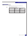
Tables
Title
1
2
3
4
Page
Slot requirements of EMC-supported Emulex adapters ...........................27
Firmware filenames ........................................................................................31
Blade server/Emulex support matrix ........................................................193
Preconfigured settings ..................................................................................208
EMC Host Connecivity with Emulex Fibre Channel HBAs and CNAs in the Windows Environment
13
Tables
14
EMC Host Connecivity with Emulex Fibre Channel HBAs and CNAs in the Windows Environment
Preface
As part of an effort to improve and enhance the performance and capabilities
of its product line, EMC from time to time releases revisions of its hardware
and software. Therefore, some functions described in this document may not
be supported by all revisions of the software or hardware currently in use.
For the most up-to-date information on product features, refer to your
product release notes.
Audience
Related
documentation
This guide is intended for customers who need to install an
EMC-approved Emulex host bus adapter (HBA) or converged
network adapter (CNA) into a Windows host environment or to
configure the Windows host for connection to an EMC storage array.
Related documents, which can be found on EMC Online Support at
https://support.emc.com, include:
◆
EMC Host Connectivity Guide for Windows
◆
EMC Unisphere documentation
◆
EMC Navisphere documentation
◆
EMC ControlCenter Navisphere Host Agent and CLI for Windows
2000 and NT Version 6.X Installation Guide
◆
Storage-System Host Utilities for Windows 2000 and NT
Administrator's Guide
◆
PowerPath for Windows Installation And Administration Guide
EMC Host Connecivity with Emulex Fibre Channel HBAs and CNAs in the Windows Environment
15
Preface
IMPORTANT
Always consult the EMC Support Matrix, available through E-Lab
Interoperability Navigator at: http://elabnavigator.EMC.com, under
the PDFs and Guides tab, for the most up-to-date information.
Conventions used in
this guide
EMC uses the following conventions for notes, cautions, and
warnings.
Note: A note presents information that is important, but not hazard-related.
IMPORTANT
An important notice contains information essential to operation of
the software.
Typographical conventions
EMC uses the following type style conventions in this document:
Normal
Used in running (nonprocedural) text for:
• Names of interface elements (such as names of windows,
dialog boxes, buttons, fields, and menus)
• Names of resources, attributes, pools, Boolean expressions,
buttons, DQL statements, keywords, clauses, environment
variables, filenames, functions, utilities
• URLs, pathnames, filenames, directory names, computer
names, links, groups, service keys, file systems, notifications
Bold
Used in running (nonprocedural) text for:
• Names of commands, daemons, options, programs,
processes, services, applications, utilities, kernels,
notifications, system call, man pages
Used in procedures for:
• Names of interface elements (such as names of windows,
dialog boxes, buttons, fields, and menus)
• What user specifically selects, clicks, presses, or types
16
Italic
Used in all text (including procedures) for:
• Full titles of publications referenced in text
• Emphasis (for example a new term)
• Variables
Courier
Used for:
• System output, such as an error message or script
• URLs, complete paths, filenames, prompts, and syntax when
shown outside of running text
EMC Host Connecivity with Emulex Fibre Channel HBAs and CNAs in the Windows Environment
Preface
Where to get help
Courier bold
Used for:
• Specific user input (such as commands)
Courier italic
Used in procedures for:
• Variables on command line
• User input variables
<>
Angle brackets enclose parameter or variable values supplied by
the user
[]
Square brackets enclose optional values
|
Vertical bar indicates alternate selections - the bar means “or”
{}
Braces indicate content that you must specify (that is, x or y or z)
...
Ellipses indicate nonessential information omitted from the
example
EMC support, product, and licensing information can be obtained on
the EMC Online Support site as described next.
Note: To open a service request through the EMC Online Support site, you
must have a valid support agreement. Contact your EMC sales representative
for details about obtaining a valid support agreement or to answer any
questions about your account.
Product information
For documentation, release notes, software updates, or for
information about EMC products, licensing, and service, go to the
EMC Online Support site (registration required) at:
https://support.EMC.com
Technical support
EMC offers a variety of support options.
Support by Product — EMC offers consolidated, product-specific
information on the Web at:
https://support.EMC.com/products
The Support by Product web pages offer quick links to
Documentation, White Papers, Advisories (such as frequently used
Knowledgebase articles), and Downloads, as well as more dynamic
content, such as presentations, discussion, relevant Customer
Support Forum entries, and a link to EMC Live Chat.
EMC Host Connecivity with Emulex Fibre Channel HBAs and CNAs in the Windows Environment
17
Preface
EMC Live Chat — Open a Chat or instant message session with an
EMC Support Engineer.
eLicensing support
To activate your entitlements and obtain your Symmetrix license files,
visit the Service Center on https://support.EMC.com, as directed on
your License Authorization Code (LAC) letter e-mailed to you.
For help with missing or incorrect entitlements after activation (that
is, expected functionality remains unavailable because it is not
licensed), contact your EMC Account Representative or Authorized
Reseller.
For help with any errors applying license files through Solutions
Enabler, contact the EMC Customer Support Center.
If you are missing a LAC letter, or require further instructions on
activating your licenses through the Online Support site, contact
EMC's worldwide Licensing team at [email protected] or call:
◆
North America, Latin America, APJK, Australia, New Zealand:
SVC4EMC (800-782-4362) and follow the voice prompts.
◆
EMEA: +353 (0) 21 4879862 and follow the voice prompts.
We'd like to hear from you!
Your suggestions will help us continue to improve the accuracy,
organization, and overall quality of the user publications. Send your
opinions of this document to:
[email protected]
18
EMC Host Connecivity with Emulex Fibre Channel HBAs and CNAs in the Windows Environment
1
Invisible Body Tag
Installation and
Configuration
This chapter describes the procedures for installing an
EMC-approved Emulex adapter into a Microsoft Windows host
environment and configuring the Windows host for connection to an
EMC storage array over Fibre Channel.
Note: Review the EMC Support Matrix for the latest information on approved
adapters and drivers.
◆
◆
◆
◆
◆
◆
◆
◆
◆
◆
◆
◆
◆
How this guide works ....................................................................... 20
Installing the adapter......................................................................... 22
Fibre Channel over Ethernet (FCoE) ............................................... 29
Booting from the external storage array ......................................... 30
Installing Windows on an external SAN disk using an EFI
RAMDISK ............................................................................................ 79
Windows 2008 Server Core operating system option................... 96
Installing adapter driver and software utilities............................. 99
Adapter BIOS upgrade.................................................................... 113
Fibre Channel over Ethernet (FCoE) Converged Network
Adapter (CNA) procedures ............................................................ 117
Establishing connectivity to the storage array............................. 163
Verifying connectivity to the storage array .................................. 164
Installing additional Unisphere/Navisphere Host Agent
software ............................................................................................. 177
Emulex NPIV solution..................................................................... 179
Installation and Configuration
19
Installation and Configuration
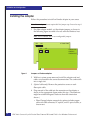
How this guide works
In an effort to simplify the installation and configuration of Emulex
Fibre Channel adapters, this guide follows a simple flow chart, as
shown in Figure 1 on page 21, that guides you through the necessary
procedures to connect your Windows server to EMC® storage arrays.
Tips on planning, miscellaneous procedures, and troubleshooting
information are located in Chapter 2, ”Miscellaneous Planning and
Procedures,” and Chapter 3, ”Troubleshooting.”
This chapter will guide you through the following steps:
1. “Installing the adapter” on page 22
2. “Booting from the external storage array” on page 30:
a. If not installing an IA-64 or EFI-based server:
– “Updating the flash firmware/BIOS” on page 30.
– “Emulex LightPulse-based Fibre Channel adapter
BIOS/boot LUN settings” on page 38.
b. If installing an IA-64 or EFI-based server:
– “Installing a RAMDISK under the EFI shell” on page 78
3. “Installing Windows on an external SAN disk using an EFI
RAMDISK” on page 79.
4. “Installing adapter driver and software utilities” on page 99.
5. “Establishing connectivity to the storage array” on page 163.
6. “Installing additional Unisphere/Navisphere Host Agent
software” on page 177
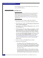
Downloading latest Emulex drivers/firmware/BIOS files
Throughout this document, there are references to updated files from
Emulex. All versions included on the Emulex CD packaged with
your adapter are current as of this document’s release. However,
there may be updates to these files that may be necessary to
download. For these, use the Emulex website,
http://www.emulex.com. From the main page on Emulex website,
click the Downloads button at the top of the page. On the resulting
support page, click the EMC link. From the EMC OEM section, it is
possible to download all of the most recent EMC-approved drivers,
20
EMC Host Connecivity with Emulex Fibre Channel HBAs and CNAs in the Windows Environment
Installation and Configuration
firmware, and boot BIOS files organized by adapter model, as well as
documentation and helpful software tools.
Start
Installing the adapter(s) into the server
Booting
from the external
storage arrays?
Booting from the External
Storage Array
YES
Create a floppy disk
with EMC-approved
driver, firmware, and
boot BIOS
N
Are you
installing an IA-64
or EFI-based
server?
Y
NO
Copy the EMC-approved
driver and firmware, and
the Intel EFI RAMDISK
driver to a USB pen drive
or floppy disk to be used
in a USB floppy drive
Install firmware and
boot BIOS from DOS
Install firmware and
EFIBoot driver from
EFI Shell
Configure the
Emulex Boot BIOS
Configure the
EFIBoot driver
Verify Array/LUN
Visibility for Boot
Install Windows OS
Install Adapter Driver and
Software Utilities
Verify Connectivity to the
Storage Array
Figure 1
GEN-000017e
Installation and configuration overview
How this guide works
21
Installation and Configuration
Installing the adapter
Follow this procedure to install an Emulex adapter in your server.
Note: Newer adapters do not require this first jumper step. Proceed to step 2.
1. For older adapter models, set the adapter jumpers as shown in
the following figure to enable it for use with the Windows host.
Note: The LP850-EMC has no user-configurable jumpers.
JX2
JX1
LP7000E-EMC
1 2 3 1 2 3
JX1
JX2
1 2 3 1 2 3
Figure 2
LP8000-EMC
LP9002-E
LP9802/DC-E
Jumpers on Emulex adapters
2. With host system power removed, install the adapter card and
cables as instructed in the server documentation. The card installs
into a single slot.
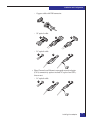
3. (Optical cable only) Remove the protective covers on each
fiber-optic cable.
4. Plug one end of the cable into the connector on the adapter as
shown in the appropriate figure under this step. (The hardware
might be rotated 90 degrees clockwise from the orientation
shown.)
• Fibre Channel adapter connectivity options include copper
cable with DB9 connector, SC optical, and LC optical cable, as
shown next.
22
EMC Host Connecivity with Emulex Fibre Channel HBAs and CNAs in the Windows Environment
Installation and Configuration
– Copper cable with DB9 connector:
– SC optical cable:
1
2
3
– LC optical cable:
1
2
3
• Fibre Channel over Ethernet converged network adapter
(CNA) connectivity options include LC optical and SFP+,
shown next.
– LC optical cable:
1
2
3
Installing the adapter
23
Installation and Configuration
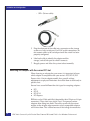
– SFP+ (Twinax cable)
5. Plug the other end of the cable into a connector on the storage
system or a hub/switch port. For FCoE switch connections, do
not connect cables to the switch port until the switch has been
properly configured.
6. Label each cable to identify the adapter and the
storage/switch/hub port to which it connects.
7. Reapply power and allow the system to boot normally.
Matching the adapter with the correct PCI slot
When choosing an adapter for your server, it is important to know
which adapter is compatible with your server's PCI/PCI-X/PCI
Express slots. Certain adapter models have specific voltage
requirements or physical limitations that allow them to work only in
specific slots.
Servers have several different bus slot types for accepting adapters:
◆
◆
◆
◆
PCI
PCI-X
PCI-X 2.0
PCI-Express
PCI slots can be 32-bit and 64-bit (denoted by their 124-pin or 188-pin
connectors.) These slots have plastic "keys" that prevent certain
adapters from fitting into them. These keys work with the cutout
notches in the adapter edge connector so only compatible adapters
will fit into them. This is done because of the voltage characteristics
24
EMC Host Connecivity with Emulex Fibre Channel HBAs and CNAs in the Windows Environment
Installation and Configuration
of the adapter. (For example, inserting a 3.3 V adapter into a 5 V slot
will cause severe damage to both the adapter and the server.)
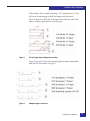
Figure 3 shows how PCI slots will appear with their keys and what
type of voltage is provided for each slot type.
Figure 3
PCI slot types and voltage key locations
Figure 4 on page 25 shows the adapter edge connectors compatible
with the PCI slots shown in Figure 3.
Figure 4
Adapter edge connectors
Installing the adapter
25
Installation and Configuration
Note adapter 5, which shows a universal adapter edge connector.
Universal adapters are compatible with both 3.3 V and 5 V PCI slots.
PCI-X (or PCI Extended) slots increase the speed with which data
travels over the bus. PCI-X slots appear identical to a 64-bit PCI slot
keyed for 3.3 V. (Refer to number 3 in Figure 3 on page 25 and
Figure 4.) PCI-X slots are backwards compatible with 3.3 V PCI
adapters and universal adapters. Inserting standard PCI adapters
into PCI-X slots will lower the bus speed as they cannot take
advantage of the improved performance.
PCI-X 2.0 is the next generation of PCI-X buses. PCI-X 2.0 increases
the bus speed again, providing more performance for adapters.
PCI-X 2.0 slots also appear identical to a 64-bit PCI slot keyed for 3.3
V. (Refer to number 3 in Figure 3 on page 25 and Figure 4.) PCI-X 2.0
is also fully backward compatible with 3.3 V PCI and PCI-X.
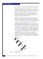
PCI Express (sometimes noted as PCIe) is a new bus type that uses
the existing PCI model, but implements it in a faster, serial protocol.
Because of the serial way it transmits data, the PCI Express bus slot
can be different sizes depending on the throughput it supports. PCI
Express slot speeds are expressed in "lanes" and are normally shown
as x1, x4, x8, and x16. Each type of slot is a different length (as shown
in Figure 5 on page 26) and adapter edge connectors will also be of
varying lengths depending on how many lanes they require for
throughput. Because of how PCI Express slots are keyed, an x1
adapter can be inserted in all four slot types, as the adapter will
negotiate with the slot to determine the highest mutually supported
number of lanes. However, an adapter requiring x16 lanes will not fit
into a smaller slot.
Figure 5
26
PCI Express slots
EMC Host Connecivity with Emulex Fibre Channel HBAs and CNAs in the Windows Environment
Installation and Configuration
Figure 6 shows x1, x4, and x16 lane slots aligned on a mainboard. You
can see how the slots are keyed so that low-lane adapters can fit into
larger slots.
PCI Express slots aligned
Figure 6
Emulex offers adapters for each bus/slot type available. Table 1
shows each of the EMC-supported Emulex adapters, and their
respective slot requirements. Be sure to consult both your server user
guide and Emulex to ensure that the adapter you want to use is
compatible with your server's bus.
Slot requirements of EMC-supported Emulex adapters (page 1 of 2)
Table 1
Adapter model
Protocol
PCI spec
BUS length
Power
Slot key
LP7000
FC
PCI 2.2
32-bit
5V
Universal
LP8000
FC
PCI 2.2 (2.1 listed?)
64-bit
5V
Universal
LP850
FC
PCI 2.2
64-bit
5V
Universal
LP9002L
FC
PCI 2.2
64-bit
3.3V
Universal
LP9002DC
FC
PCI 2.2
64-bit
3.3V
Universal
LP982
FC
PCI-X 1.0a & PCI 2.2
64-bit
3.3V
Universal
LP9802
FC
PCI-X 1.0a & PCI 2.2
64-bit
3.3V
Universal
LP9802DC
FC
PCI-X 1.0a & PCI 2.2
64-bit
3.3V, 5V
3.3V
LP1050/LP1050DC
FC
PCI-X 1.0a & PCI 2.3
64-bit
3.3V, 5V
Universal
LP10000/LP10000DC
FC
PCI-X 1.0a & PCI 2.3
64-bit
3.3V, 5V
Universal
LP1050Ex/LP10000ExDC
FC
PCI Express
x4 lane
3.3v
n/a
Installing the adapter
27
Installation and Configuration
Slot requirements of EMC-supported Emulex adapters (page 2 of 2)
Table 1
Adapter model
Protocol
PCI spec
BUS length
Power
Slot key
LP1150/LP11000/LP11002
FC
PCI-X 2.0 & PCI 3.0
64-bit
3.3v
3.3v
LPe1150/LPe11000/LPe11002
FC
PCI Express
x4 lane
3.3v
n/a
LPe1250
FC
PCI Express
x4 lane
3.3v
n/a
LPe12000
FC
PCI Express
x4 lane
3.3v
n/a
LPe12002
FC
PCI Express
x4 lane
3.3v
n/a
LPe16000B / LPe16002B
FC
PCI Express
x8 lane
3.3v
n/a
LP21000
FCoE
PCI Express
x8 lane
3.3v
n/a
LP21002
FCoE
PCI Express
x8 lane
3.3v
n/a
Note that a few adapters are keyed universally, but require 5 V power
(LP7000, LP8000, LP850.) They will fit into a 3.3 V PCI/PCI-X slot, but
will not work unless the slot is capable of universal (3.3 V and 5 V)
signaling. Consult your server user guide or manufacturer.
The LP9802DC, while capable of 3.3 V or 5 V signaling operation, fits
only into a 3.3 V PCI/PCI-X slot. Remember, some of the older
adapters are tall (also referred to as full-height) and may not fit into a
server with a low-profile chassis. These factors must be considered
before implementing your configuration to avoid unnecessary delays
and possible equipment swaps or returns.
Note: The Emulex LP2100x FCoE CNAs require servers that can
accommodate full-height, full-length PCI Express adapters. Always refer to
the EMC Support Matrix for the most up-to-date information on which
servers support these adapters.
28
EMC Host Connecivity with Emulex Fibre Channel HBAs and CNAs in the Windows Environment
Installation and Configuration
Fibre Channel over Ethernet (FCoE)
EMC supports Emulex Fibre Channel over Ethernet (FCoE)
Converged Network Adapter (CNA). FCoE adapters represent a
method to converge both Fibre Channel and Ethernet traffic over a
single physical link to a switch infrastructure that manages both
storage (SAN) and network (IP) connectivity within a single unit.
The benefits of FCoE technology become apparent in large data
centers:
◆
Where dense, rack-mounted and blade server chassis exist.
◆
Where physical cable topology simplification is a priority.
◆
In virtualization environments, where several physical storage
and network links are commonly required.
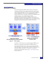
The installation of the Emulex FCoE CNA provides the host with an
Intel-based 10 Gb Ethernet interface (using the existing in-box
drivers), and an Emulex Fibre Channel adapter interface.
Upon installation of the proper driver for the FCoE CNA, the Fibre
Channel interface will function identically to that of a standard
Emulex Fibre Channel HBA. The FCoE CNA simply encapsulates
Fibre Channel traffic within Ethernet frames. As such, FC-based
content within this guide also applies directly to Emulex FCoE CNAs.
In-depth information about FCoE and its supported features and
topologies can be found in the "Fibre Channel over Ethernet (FCoE)"
chapter of the EMC Networked Storage Topology Guide, available
through E-Lab Interoperability Navigator at:
http://elabnavigator.EMC.com.
For CNA configuration procedures, refer to “Fibre Channel over
Ethernet (FCoE) Converged Network Adapter (CNA) procedures” on
page 117.
Fibre Channel over Ethernet (FCoE)
29
Installation and Configuration
Booting from the external storage array
This section contains the following information on booting from the
external storage array:
◆
“Updating the flash firmware/BIOS”, next
◆
“Emulex LightPulse-based Fibre Channel adapter BIOS/boot
LUN settings” on page 38
◆
“Installing a RAMDISK under the EFI shell” on page 78
Updating the flash firmware/BIOS
Each Emulex Fibre Channel controller has flash-upgradeable
firmware and BIOS. In most instances, it is necessary to keep only the
firmware current, since the BIOS is applied only when using
connected storage as a boot device.
The CD-ROM contains the EMC-approved firmware files at the time
of this document's release. If updated firmware is available,
download it as described under “Downloading latest Emulex
drivers/firmware/BIOS files” on page 20.
The firmware and BIOS files are typically in a .zip file that contains
different combinations of firmware and BIOS images. Extract the
downloaded file, and refer to the included readme.txt to determine
which filename image to use. For older adapter models, you should
always use the *.awc files; typically there are two from which to
choose. One includes the boot BIOS with the firmware, and the other
does not. The *.awc file that includes the boot BIOS is named with
and additional c (i.e., CDC392a2.awc).
Most recent adapter families provide a single firmware file with an
.all extension. These firmware images do not have BIOS combined
with the firmware, so a separate load for the Boot BIOS is required.
30
EMC Host Connecivity with Emulex Fibre Channel HBAs and CNAs in the Windows Environment
Installation and Configuration
Firmware filenames
Table 2 lists the filenames associated with each supported adapter.
Table 2
Firmware filenames
Adapter model
Firmware file
BIOS file
LP8000
DDCxxxxx.AWC
DBxxxxx.PRG
LP9000
CDCxxxxx.AWC
CBxxxxx.PRG
LP9802
HDxxxxx.ALL
HBxxxxx.PRG
LP9802DC
HFxxxxx.ALL
HBxxxxx.PRG
LP982
LFxxxxx.ALL
LBxxxxx.PRG
LP10000/DC and LP10000/DCEx
TDxxxxx.ALL
TBxxxxx.PRG
LP1050/DC and LP1050Ex
MFxxxxx.ALL
MBxxxxx.PRG
LP1150
JFxxxxx.ALL
JBxxxxx.PRG
LP11000
BDxxxxx.ALL
BDxxxxx.PRG
LP11002
BFxxxxx.ALL
BBxxxxx.PRG
LPe1150
WFxxxxx.ALL
WBxxxxx.PRG
LPe11000
ZDxxxxx.ALL
ZBxxxxx.PRG
LPe11002
ZFxxxxx.ALL
ZBxxxxx.PRG
LPe1250
OFxxxxx.ALL
OBxxxxx.PRG
LPe12000 and LPe12002
UDxxxxx.ALL
UBxxxxx.PRG
LP21000
ADxxxxxALL
AUxxxxxPRG
LP21002
AFxxxxxALL
AUxxxxxPRG
If you are upgrading the firmware and BIOS, update the firmware
first, because it may contain an older BIOS, which you can update
separately after. Copy the selected firmware and boot BIOS file(s) to a
diskette and follow the appropriate upgrade procedures detailed in
this chapter:
◆
“Upgrading using a DOS boot diskette” on page 32
◆
“Upgrading adapter firmware/BIOS on IA-64 class servers” on
page 37
Booting from the external storage array
31
Installation and Configuration
◆
“Updating the adapter firmware using the HBAnyware utility”
on page 109
◆
“Installing Fibre Channel firmware on an Emulex CNA” on
page 120
ELXCFG and LPUTIL can be used as well, but are not covered in this
guide. For general use instructions of these utilities, refer to Emulex
documentation or “ELXCFG.EXE” on page 195.
Upgrading using a DOS boot diskette
This section deals exclusively with Emulex' former DOS utility,
LP6DUTIL.EXE. This utility was formerly packaged with firmware
and BIOS packages to allow users to perform HBA maintenance and
code loads from DOS.
This LP6DUTIL.EXE utility is no longer packaged with code from
Emulex, but there is currently a DOS Offline Utility kit and manual
available to do wnload from the Emulex website:
http://www.emulex.com/downloads/emulex/cnas-and-hbas/utilities/offline-utilities
If you are in need of a DOS utility to load Boot BIOS code to an HBA,
EMC recommends downloading and using this new DOS Offline
Utility. The user manual for this utility is also available at the above
Emulex website address. If possible, EMC recommends using the
Emulex HBAnyware utility to load HBA/CNA firmware and BIOS
code.
The Emulex CD-ROM contains the latest EMC-approved firmware
and BIOS files at the time of creation of the CD-ROM. If more recent
files exist, you can locate them on the Emulex website. Refer to
“Downloading latest Emulex drivers/firmware/BIOS files” on
page 20.
Follow these steps to upgrade the flash firmware from a
DOS-bootable diskette:
1. Format a 3.5-inch diskette to be system bootable and extract the
firmware and flash utility files from the archive file (.zip or
self-extracting .exe) onto the diskette. Ensure lp6dutil.exe and
the source files are in the same directory. (Refer to Table 2 on
page 31 to ensure the correct .ALL, .AWC, and/or *.PRG file is
used.)
32
EMC Host Connecivity with Emulex Fibre Channel HBAs and CNAs in the Windows Environment
Installation and Configuration
Note that each adapter model uses a specific letter designation for
its firmware and BIOS filenames. Be sure check the readme
included with the upgrade package to ensure you have all of
appropriate files before proceeding to the next step.
2. Reboot your Windows host system using a DOS diskette.
3. At the A:\> prompt, insert the diskette that contains the Emulex
BIOS files (created in step 1).
Note: For users upgrading LP7000, LP8000, and LP900X adapters, follow
steps 4 through 13. For LP98XX and later families (including PCI-Express
adapters), refer to “Lp6dutil for LP98XX and later adapter families” on
page 33.
4. At the A:\> prompt, type lp6dutil and press Enter.
The utility performs diagnostic tests on the installed adapter(s).
You may be required to press Enter after each test so the program
can move on to the next. Once the diagnostics are complete, the
main menu appears.
5. Type 5 and press Enter, to select Maintenance.
6. Type 1 and press Enter, to select Upgrade Firmware.
7. Enter the range of adapters to flash; for example: 1-4 (for four
adapters).
8. Enter the Firmware Image filename, including the path. The
firmware image file should be on the same disk as LP6DUTIL.EXE.
Refer to Table 2 on page 31 for the firmware file to use.
9. When prompted, type 1 and press Enter to proceed with the
upgrade for the first controller.
10. When prompted, type 1 and press Enter to reset the adapter after
loading is complete.
11. Repeat steps 8 and 9 for each adapter in the range entered in
step 6.
12. When all adapters are loaded, type 0 and press Enter at the
Maintenance menu to return to the main menu.
13. Type 7 and press Enter at the main menu to exit the flash utility.
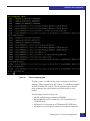
Lp6dutil for LP98XX and later adapter families
Booting from the external storage array
33
Installation and Configuration
Emulex has released an updated lp6dutil.exe application for loading
adapter firmware and other adapter maintenance tasks. The new
version is included in all recent firmware packages and works
differently than the version described in the previous section.
The following procedure assumes you have booted your server with
a DOS-bootable diskette, and have inserted the diskette with the
firmware, BIOS, and lp6dutil.exe files on it.
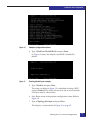
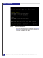
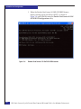
1. At the A:\> prompt, type lp6dutil and press Enter.
The utility performs diagnostic tests on the installed adapter(s)
and displays a text menu at the top of the screen.
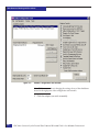
Figure 7
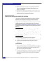
LP6DUTIL main screen
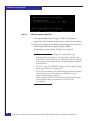
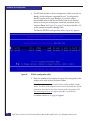
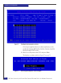
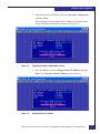
2. Press Alt-L to open the Flash menu. From this menu, press D to
select Download (or use the arrow keys and press Enter).
34
EMC Host Connecivity with Emulex Fibre Channel HBAs and CNAs in the Windows Environment
Installation and Configuration
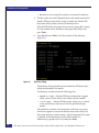
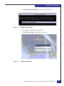
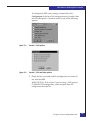
Figure 8
LP6DUTIL flash menu
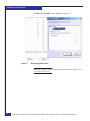
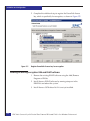
3. Type in the filename of the firmware file you wish to load. Or,
using the tab key, highlight the file under the Files box (use up
and down arrow keys to select your file).
When you have highlighted the correct file, press Enter, and use
the tab key to highlight Adapters.
Use the up and down arrow keys to select the adapter you wish to
load and press Enter. Then use the tab key to select OK and press
Enter.
Booting from the external storage array
35
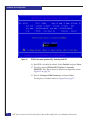
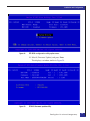
Installation and Configuration
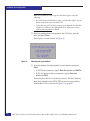
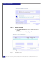
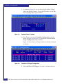
Figure 9
Selecting the adapter to load
The utility verifies the file and performs the firmware upgrade.
Once complete, the menu at the top of the screen might have
disappeared. If so, press Alt-L again to retrieve the menu.
4. Repeat steps 2 and 3 to load firmware to any other adapters.
5. Once your adapters are upgraded, press Alt-F to open the File
menu, and select Exit to quit the LP6DUTIL.EXE tool.
If you are also loading a boot BIOS to your adapter(s), steps 2 and
3 apply. Using the download technique, ensure that the correct
boot BIOS file is selected for your adapter.
Enabling/disabling the boot BIOS
Once the boot BIOS is loaded to the adapters, it is enabled by default.
If it is not enabled, the adapter is unconfigurable for external boot.
To enable or disable the boot BIOS on your adapter:
1. Press Alt-L to open the Flash menu.
2. Select Display Flash.
3. Verify the adapter has a valid boot BIOS image loaded. Then
press Esc to close the Flash Load List window.
4. Press Alt-L to open the Flash menu.
36
EMC Host Connecivity with Emulex Fibre Channel HBAs and CNAs in the Windows Environment
Installation and Configuration
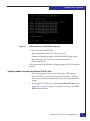
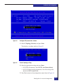
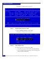
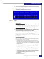
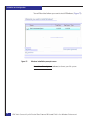
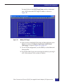
5. Select Boot BIOS.
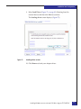
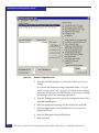
This displays the Change Boot BIOS State window (Figure 10).
Figure 10
Change Boot BIOS State window
6. Use the up/down arrow keys to select the adapter in the
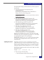
Adapters box.
7. Use the tab key to highlight the BIOS Image box.
Use the up/down arrow keys to select the Boot BIOS image. Be
sure to choose the item called Boot BIOS enabled (or disabled).
8. Use the tab key to highlight the Change button, and then press
the spacebar. This toggles the boot BIOS image between enabled
and disabled.
9. Use the tab key to highlight OK, and press Enter.
10. Press Alt-F and select Exit to exit the lp6dutil.exe utility.
Upgrading adapter firmware/BIOS on IA-64 class servers
adapter firmware/BIOS can be updated from the Windows operating
system using the utilities listed under “Updating the adapter
firmware using the HBAnyware utility” on page 109.
Firmware/BIOS for the adapter can also be updating using the
procedure beginning on page 47.
Booting from the external storage array
37
Installation and Configuration
Emulex LightPulse-based Fibre Channel adapter BIOS/boot LUN settings
This section describes the steps required to configure an Emulex
adapter boot BIOS for allowing an array-attached LUN to be used as
a boot disk for the server and includes information for the following:
◆
“Legacy (x86 and most x64-based sServers) boot BIOS
configuration” on page 39
◆
“Updating adapter firmware from Emulex EFI-BIOS utility” on
page 47
◆
“Booting from SAN with HP Itanium servers with EMC storage”
on page 63
This section assumes that the following steps are already completed:
◆
In direct-attach configurations, an adapter has a physical
connection to the array port.
◆
In fabric-attach configurations, an adapter has a physical
connection to the switch/fabric, and is zoned to the array, such
that a single adapter to be used for boot has one logical I/O path
to the array. Refer to your switch documentation for details.
◆
The Emulex adapter is configured to allow boot BIOS
functionality. Refer to “Updating the flash firmware/BIOS” on
page 30, which references the LP6DUTIL utility used to enable
boot BIOS functionality.
Before configuring adapter settings to boot from an array-based
LUN, your server's settings should be adjusted to disable booting
from an internal system drive. The procedure for disabling boot from
an internal system drive is largely dependent upon the server
platform:
38
◆
In some instances, internal boot can be disabled via entering the
onboard SCSI/RAID controller's BIOS utility. For example, an
Adaptec-based controller can be configured by pressing Ctrl-A,
when the Adaptec banner is displayed during power-on self test.
◆
Some servers require entering the system BIOS utility to either
disable boot from an internal drive, or to change the controller
boot order, such that the boot adapter is enumerated before the
internal disk controller. This allows the array-attached LUN to be
the first disk visible to the server. Refer to your server
documentation for details.
EMC Host Connecivity with Emulex Fibre Channel HBAs and CNAs in the Windows Environment
Installation and Configuration
◆
In some server instances, boot from an internal drive cannot be
explicitly disabled. In this case, the internal drive(s) must be
physically disconnected or removed from the server. Refer to
your server documentation for details.
IMPORTANT
In some cases, re-adding an internal drive (after having previously
removed it and configured an adapter for boot) may result in the
internal drive being re-enumerated as the first drive. This may
modify the boot order so the server will attempt to boot from the
internal drive rather than the intended array-based LUN, and fail to
boot. Make sure that appropriate precautions are taken to ensure
that the server will properly boot from an array-based LUN before
re-adding an internal system drive.
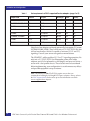
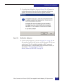
Legacy (x86 and most x64-based sServers) boot BIOS configuration
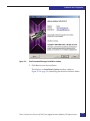
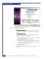
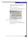
1. When the Emulex banner (Figure 11) appears during power-on
self test (POST), press Alt-E to enter the Emulex Configuration
utility.
Figure 11
Emulex banner
Note: If no Emulex banner is displayed during POST, verify that a
bootable BIOS image has been loaded on the adapter and that the image
has been explicitly enabled. (Refer to “Updating the adapter firmware
using the HBAnyware utility” on page 109 for details on loading a
bootable BIOS image on the adapter, and “Updating the flash
firmware/BIOS” on page 30.)
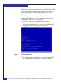
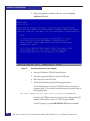
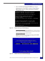
The utility opens to the main Emulex LightPulse BIOS Utility
page (Figure 12).
Booting from the external storage array
39
Installation and Configuration
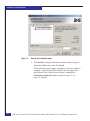
Figure 12
Emulex LightPulse BIOS utility
In this example, only a single adapter is installed. If multiple
adapters are installed, there will be multiple adapter entries. The
order of the adapter instances listed is the order they will be
scanned for a boot device; note that this does not necessarily
correspond to PCI slot numbering.
2. Select the row number of the adapter instance that corresponds to
the adapter that will be used for boot and press Enter.
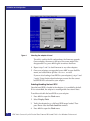
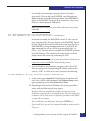
This displays a screen similar to Figure 13.
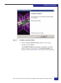
Figure 13
Adapter configuration selection
Note: For boot-from-SAN configurations, EMC recommends setting the
default BIOS settings before configuring boot settings. This will clear the
board of any settings that may be left over from a previous install if the
adapter was previously used in another system. Press <d> at the adapter
Configuration Selection screen to set the adapter default settings.
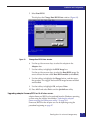
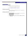
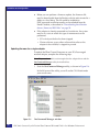
3. Type 2 (Configure This Adapter’s Parameters) and press Enter.
Various configuration options are presented, as shown in
Figure 14 on page 41.
40
EMC Host Connecivity with Emulex Fibre Channel HBAs and CNAs in the Windows Environment
Installation and Configuration
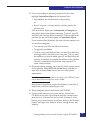
Figure 14
Adapter configuration options
4. Type 1 (Enable or Disable BIOS) and press Enter.
As Figure 15 shows, the adapter's boot BIOS is disabled by
default.
Figure 15
Enabling/disabling an adapter
5. Type 1 (Enable) and press Enter.
The screen (as shown in Figure 15) is refreshed, showing a BIOS
status of Enabled. This allows the server to use an array-attached
LUN to be used as a boot device.
6. Press Esc to return to the previous configuration screen (Refer to
Figure 14).
7. Type 4 (Topology Selection) and press Enter.
This displays a screen similar to Figure 16 on page 42.
Booting from the external storage array
41
Installation and Configuration
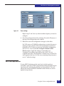
Figure 16
Topology selection
8. Select the topology based on your attach environment:
• In FC-AL/direct attach environments, press Enter to accept
the default of option 1 (Auto Topology: Loop first).
• In FC-SW environments, type 2 (Auto Topology: Pt to Pt first)
and press Enter.
The Topology information near the top of the screen reflects your
selection.
9. Press Esc to return to the previous configuration screen (Figure 15
on page 41).
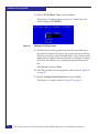
10. Type 3 (Change PLOGI Retry Timer) and press Enter.
This displays a screen similar to Figure 17.
Figure 17
Setting the PLOGI retry timer
The PLOGI Retry Timer specifies the amount of time following a
port reset the adapter will wait to log in again and rescan the bus
for devices.
42
EMC Host Connecivity with Emulex Fibre Channel HBAs and CNAs in the Windows Environment
Installation and Configuration
11. Type 2 (Change PLOGI Retry Timer to 50 msec) and press Enter.
Setting a value of 50 msec allows more time for the login and
rescan functions to complete. A setting of 50 msec takes five to six
seconds per device found on the bus.
12. Press Esc twice to return to the main Emulex LightPulse BIOS
Utility screen (Figure 12 on page 40).
Note: If you have changed the topology or if BIOS not ready appears,
reboot the host and re-enter the BIOS to this point to continue.
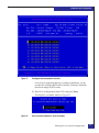
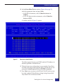
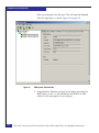
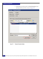
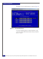
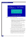
13. Type 1 (Configure Boot Devices) and press Enter.
This displays a list of saved boot devices (Figure 18).
Figure 18
Saved boot devices
A list of up to eight boot devices, in order of preference, can be
saved in the adapter's BIOS utility. Initially, all entries should be
listed as Unused.
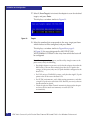
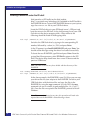
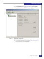
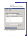
14. Type 1 to set the primary boot LUN, and press Enter.
This displays a screen similar to Figure 19 on page 44.
Booting from the external storage array
43
Installation and Configuration
Figure 19
Setting the primary boot LUN
A list representing all array targets visible to the adapter is
presented. In this example, a single array is zoned to the adapter.
15. Select the two-digit row number corresponding to the array to be
used for boot (01 in this example) and press Enter.
This displays a screen similar to Figure 20 on page 45.
Note: If no entries (other than 00) appear, verify the following:
• If multiple adapters are present, verify the adapter selected in the
BIOS utility is the same adapter that currently provides the I/O path
to the storage. (At this point, only one I/O path should be configured
to the boot LUN.)
• For VNX™ series or CLARiiON® systems, verify the single I/O path
points to the SP that owns the boot LUN.
• For FC-SW environments, verify fabric-zoning parameters, such that
a single I/O path exists to the boot LUN. (Refer to your array
software documentation for details.)
• Check the physical Fibre Channel connectivity between the adapter
and array (direct-attach environment) or switch (FC-SW
environment).
44
EMC Host Connecivity with Emulex Fibre Channel HBAs and CNAs in the Windows Environment
Installation and Configuration
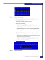
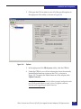
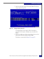
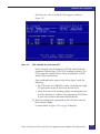
Figure 20
Scanning for available boot LUNs
16. Enter the two digits of the starting LUN address, and press Enter.
This setting specifies the LUN address where the utility will begin
scanning for available boot LUNs. For example, entering 0B will
result in the utility scanning from LUN address 0B for available
LUNs, skipping addresses 00 through 0A. In this example,
entering 00 instructs the utility to scan from 00, which is the first
LUN address. This will scan all LUNs visible to the adapter.
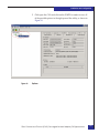
After the scan, a list of available LUNs appears, similar to
Figure 21.
Figure 21
LUNs available for use as boot LUN
In this example, entry 01 references LUN 00, which holds the
Symmetrix® Volume Logix VCM (LUN masking) database. This
LUN cannot be used by the host. Entry 02 references LUN 04,
which will be used for boot.
Booting from the external storage array
45
Installation and Configuration
Note: If no numbered entries appear in the above figure, verify the
following:
• For VNX series or CLARiiON systems, verify that the single I/O path
points to the SP that owns the boot LUN.
• Verify that array LUN masking settings are configured such that this
adapter has visibility to the appropriate LUN. Refer to your array
software documentation for details.
17. Select the number that corresponds to the LUN to be used for
boot, and press Enter.
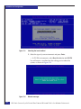
This displays a screen similar to Figure 22.
Figure 22
Selecting the boot method
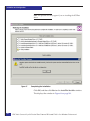
18. Type the number that corresponds to your selection and press
Enter:
• In FC-SW environments, type 1 (Boot this device via WWPN).
• In FC-AL/direct-attach environments, type 2 (Boot this
device via DID).
This re-displays the list of saved boot devices. The first (Primary
Boot) entry identifies the WWN/DID of the array port and the
selected boot LUN, as shown in Figure 23 on page 47.
46
EMC Host Connecivity with Emulex Fibre Channel HBAs and CNAs in the Windows Environment
Installation and Configuration
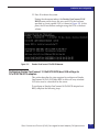
Figure 23
Saved boot devices with WWN of array port
19. Press X to exit the BIOS utility.
When prompted to reboot the system, press Y.
During the subsequent reboot, the Emulex BIOS banner screen
shows the array and LUN that has been specified as a
boot-capable LUN.
At this point, the OS Installation can begin using this LUN as the boot
volume.
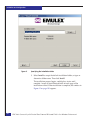
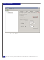
Updating adapter firmware from Emulex EFI-BIOS utility
1. Prior to booting the server, ensure that media (USB memory
drive, CD-ROM, or diskette) that contains the Emulex EFI boot
code/utility you downloaded earlier is physically present in the
system.
2. Following POST of the server, the Firmware Boot Manager menu
(Figure 24 on page 48) appears. Using the arrow keys, select EFI
Shell and press Enter.
Booting from the external storage array
47
Installation and Configuration
Figure 24
Firmware boot manager menu
The EFI shell will open and the Device Mapping Table (Figure 25
on page 49) may be listed by default. If the Device Mapping Table
is not listed, type map and press Enter.
48
EMC Host Connecivity with Emulex Fibre Channel HBAs and CNAs in the Windows Environment
Installation and Configuration
Figure 25
Device mapping table
The file systems available to the server are listed in the Device
Mapping Table, referenced by fsN (where N is a different number
for each available file system). The description next to the fsN
entry references the type of media on which the file system
resides.
In the example shown in Figure 25:
• fs0, fs1, and fs2 refer to memory RAMdisks.
• fs3 and fs4 refer to file systems on a CD inserted into the
CD-ROM drive.
• fs5 refers to a file system on a USB memory-FLASH drive.
Booting from the external storage array
49
Installation and Configuration
• fs6 refers to an existing file system on an internal hard drive.
3. The file system you select depends upon what media contains the
Emulex EFI boot code/utility. In this example, the Emulex EFI
boot code/utility resides on the USB memory drive.
Point the EFI shell to the proper file system by typing fsN: (where
N is the number which references the proper file system) and
press Enter.
4. Type dir and press Enter to list the contents of the directory
(Figure 26).
Figure 26
Directory listing
The directory listing should contain the Emulex EFI boot code/
utility downloaded to the media.
The directory should contain the following files:
• elxclinnnn.efi — Emulex EFI boot configuration support
utility, where NNNN refers to the utility version number.
• xxxxxxx.prg — Emulex EFI boot code, where xxxxxxx refers
to the version boot code version for the specified adapter
model.
If the directory contents are inconsistent with what you expect,
and do not appear to contain the Emulex boot code/utility, the
file system select may not be correct. Verify the proper file system
is selected. If the Emulex boot code/utility resides in a
subdirectory, type cd subdirectory and press Enter.
50
EMC Host Connecivity with Emulex Fibre Channel HBAs and CNAs in the Windows Environment
Installation and Configuration
5. The elxclinnnn.efi configuration support utility file must be
loaded in the EFI shell to configure the Emulex adapter. Type load
elxclinnnn.efi (where nnnn refers to the specific version
number present on your media) and press Enter.
In the example in Figure 27, the configuration support utility file
is named elxcli311a4.efi.
Figure 27
EFI boot configuration support utility
6. Emulex adapters can now be configured via the EFI shell. Type
drivers and press Enter to obtain a list of loaded drivers in the EFI
shell.
7. Make note of the first hexadecimal value listed on the line with
Emulex SCSI pass Thru Driver. In the example in Figure 28, the
driver handle is 8C.
Figure 28
Loaded drivers in the EFI shell
8. The EFI shell includes a driver configuration utility, accessed via
drvcfg, which configures supported drivers. To configure the
Emulex-specific driver, type drvcfg -s driverhandle (where
driverhandle refers to the driver handle listed for the Emulex
driver in the output of the drivers command, described above)
and press Enter. (In Figure 28 on page 51, the driver handle is 8C,
so the command entered is drvcfg -s 8C.)
Booting from the external storage array
51
Installation and Configuration
The Emulex EFI BIOS configuration utility (Figure 29) appears.
Figure 29
EFI BIOS configuration utility
9. Select the number of the adapter instance that corresponds to the
adapter to be used for boot and press Enter.
Note: If multiple adapters are installed, there will be multiple adapter
entries. The order of the adapter instances listed is the order they will be
scanned for a boot device; this does not necessarily correspond to PCI
slot numbering. In Figure 29, adapter entry 001 is used for boot.
A window similar to Figure 30 on page 53 appears.
52
EMC Host Connecivity with Emulex Fibre Channel HBAs and CNAs in the Windows Environment
Installation and Configuration
Figure 30
EFI BIOS configuration utility option menu
10. Select 2 (Firmware Update) and press Enter.
This displays a window similar to Figure 31 on page 54.
Booting from the external storage array
53
Installation and Configuration
Figure 31
EFI BIOS firmware update utility
11. The utility prompts for a directory path. Type the directory path
relative to the root directory and press Enter.
In Figure 31, the directory path (as shown in the EFI prompt in
Figure 26 on page 50) without the file system is \emulex.
12. The utility prompts for the EFI boot code/firmware filename.
Type the filename (xxxxxxx.prg as it is found in the media
containing the Emulex EFI boot/code utility, and press Enter. In
Figure 31, the EFI boot code is shown (in the Figure 26 directory
listing) as je311a4.prf.
13. The utility reports various steps of the boot code/firmware
update as Done and Updated.
When prompted, press any key to return to the previous menu
(Figure 30 on page 53).
14. Select 1 (Setup Utility) and press Enter.
This displays a window similar to Figure 32 on page 55.
54
EMC Host Connecivity with Emulex Fibre Channel HBAs and CNAs in the Windows Environment
Installation and Configuration
Figure 32
EFI BIOS firmware update utility: Enabling/disabling the BIOS
15. Select 1 (Enable or Disable BIOS) and press Enter.
This displays a window similar to Figure 33 on page 56.
Booting from the external storage array
55
Installation and Configuration
Figure 33
EFI BIOS firmware update utility: Enabling the BIOS
16. Boot BIOS is disabled by default. Select Enabled and press Enter.
17. The utility reports EFI-Boot BIOS Option is Currently
ENABLED. Press Esc to return to the prior configuration screen
(Figure 32 on page 55).
18. Select 2 (Configure HBA Parameters) and press Enter.
This displays a window similar to Figure 34 on page 57.
56
EMC Host Connecivity with Emulex Fibre Channel HBAs and CNAs in the Windows Environment
Installation and Configuration
Figure 34
Configure HBA parameters window
19. Select 2 (Topology Selection) and press Enter.
This displays a window similar to Figure 35.
Figure 35
Current topology setting
20. Select the appropriate setting and press Enter:
• In FC-SW environments, select AUTO (start Point to Point).
• In FC-AL/direct-attach environments, leave the setting at the
default of AUTO (start FCAL).
21. Press Esc to return to the configuration screen shown in Figure 34.
Booting from the external storage array
57
Installation and Configuration
22. Select 3 (PLOGI Retry Timer) and press Enter.
This displays a window similar to Figure 36, which shows the
default setting of NO RETRYs.
Figure 36
Setting the PLOGI retry timer
23. The PLOGI retry timer specifies the amount of time following a
port reset the adapter will wait to log in again and rescan the bus
for devices. Setting a value of 50 msec allows a retry interval of 50
milliseconds for login and rescan functions to complete. A setting
of 50 msec will take five to six seconds per device found on the
bus.
Select 50 msec and press Enter.
24. Press Esc to return to the configuration screen shown in Figure 32
on page 55.
25. Select 3 (Configure Boot Parameters) and press Enter.
This displays a window similar to Figure 37 on page 59.
58
EMC Host Connecivity with Emulex Fibre Channel HBAs and CNAs in the Windows Environment
Installation and Configuration
Figure 37
Configure boot parameters window
A list of up to eight boot devices, in order of preference, can be
saved in the adapter's BIOS utility. Initially, all entries should be
listed with empty WWN values.
26. Select 1 to set the primary boot LUN, and press Enter.
This displays a window similar to Figure 38.
Figure 38
Instructing the adapter to scan for targets
Booting from the external storage array
59
Installation and Configuration
27. Select 1 (Scan Targets) to instruct the adapter to scan for attached
targets, and press Enter.
This displays a window similar to Figure 39.
Figure 39
Targets
28. Select the number that corresponds to the array target port from
which the boot will be configured, and press Enter.
This displays a window similar to Figure 40 on page 61.
In Figure 39, the array designated by 002: DID:2C1900
WWN:5006048A CD201641 is the array from which the boot will
be configured.
Note: If no target numbers appear, and the utility simply returns to the
prior screen, verify the following:
• If multiple adapters are present, verify that the adapter selected in the
BIOS utility is the one that currently provides the I/O path to the
storage. (At this point, only one I/O path should be configured to the
boot LUN.)
• For VNX series or CLARiiON systems, verify that the single I/O path
points to the SP that owns the boot LUN.
• For FC-SW environments, verify fabric zoning parameters, such that
a single I/O path exists to the boot LUN. Refer to your array software
documentation for details.
• Check the physical Fibre Channel connectivity between the adapter
and array (direct-attach environment) or switch (FC-SW
environment).
60
EMC Host Connecivity with Emulex Fibre Channel HBAs and CNAs in the Windows Environment
Installation and Configuration
Figure 40
LUNs for target array port
29. Select the number that corresponds to the LUN to be used for
boot, and press Enter.
This displays a window similar to Figure 41.
In the Figure 40 example:
• Entry 01 references LUN 00, which holds the Symmetrix
Volume Logix VCM (LUN masking) database, cannot be used
by the host.
• Entry 02 references LUN 10 (this is a decimal representation;
which corresponds to a hexadecimal value of 0A), which will
be used for boot.
Note: If no numbered entries appear in the above figure, verify the
following:
• For VNX series or CLARiiON systems, verify that the single I/O path
points to the SP that owns the boot LUN.
• Verify that array LUN masking settings are configured so that this
adapter has visibility to the appropriate LUN. Refer to your array
software documentation for details.
Figure 41
Selected boot device
Booting from the external storage array
61
Installation and Configuration
30. In the Selected Boot Device window (Figure 41 on page 61),
select the appropriate item and press Enter:
• In FC-SW environments, select 1 (Boot this device via
WWPN).
• In FC-AL/direct-attach environments, select 2 (Boot this
device via DID).
A window similar to Figure 42 appears.
Figure 42
Boot device identification
The utility reports the array port WWN and the LUN address (in
decimal) specified as the boot device.
31. The boot from array configuration is now complete. Press Esc to
exit from each menu screen until the utility is closed and you are
prompted: Action Required is Press [ENTER] to continue.
62
EMC Host Connecivity with Emulex Fibre Channel HBAs and CNAs in the Windows Environment
Installation and Configuration
32. Press Enter twice to return to the EFI shell. The EFI shell can now
be exited, and the OS Installation can begin using the specified
array-based LUN as the boot volume.
Booting from SAN with HP Itanium servers with EMC storage
Setting up the server
Before booting from a SAN, set up the server as follows:
1. Download and install the latest system firmware.
2. Remove the internal hard disks.
3. Record the WWN of each adapter port (each adapter should be
tagged).
4. Install all adapters and connect one port to be targeted for
booting.
Preparing the USB
drive
Files required for the installation can be downloaded onto a USB
drive. Download the following files using the links below and copy
to the USB drive.
◆
ramdisk.efi — Intel provides this tool in their EFI toolkit. The
toolkit in available for download at
http://www.intel.com/technology/efi in Tools\Application
Toolkit.
◆
diskpart.efi — This Intel provided disk utility can be found at
http://www.intel.com/technology/efi in the EFI Disk Utilities
link.
◆
EFI Boot code/utility for your adapter — This can be
downloaded from the EMC section at www.emulex.com.
◆
Adapter driver
a. Download the AutoPilot Install Kit from the EMC section at
www.emulex.com to a temporary directory on a computer, not
the USB drive. This file contains the Base driver and
HBAnyware utility.
b. After downloading the AutoPilot executable, select open to
start the installation.
c. Select Next and then Install to start the installation.
d. Uncheck the Start AutoPilot Installer checkbox and select
finish.
Booting from the external storage array
63
Installation and Configuration
e. The driver files are located at C:\Program
Files\Emulex\AutoPilot Installer\Drivers\Storport\IA64\.
Copy the contents of this directory to the USB drive.
Preparing the adapter
Before booting from a SAN, the EFI Boot BIOS must be installed and
the adapter Boot BIOS enabled.
Adapter EFI firmware configuration
1. Prior to booting the server, ensure that media (USB memory drive
or CD-ROM that contains the Emulex EFI boot code/utility you
downloaded earlier is physically present in the system.
2. Following POST of the server, a Boot Menu the same or similar to
(Figure 43) appears. Using the arrow keys, select EFI Shell and
press Enter.
Figure 43
Firmware boot manager menu
The EFI shell will open and the Device Mapping Table (Figure 44
on page 65) may be listed by default. If the Device Mapping Table
is not listed, type map and press Enter.
64
EMC Host Connecivity with Emulex Fibre Channel HBAs and CNAs in the Windows Environment
Installation and Configuration
Figure 44
Device mapping table
The file systems available to the server are listed in the Device
Mapping Table, referenced by fsN (where N is a different number
for each available file system). The description next to the fsN
entry references the type of media on which the file system
resides.
In the example shown in Figure 44:
• fs0, fs1, and fs2 refer to memory RAMdisks.
• fs3 and fs4 refer to file systems on a CD inserted into the
CD-ROM drive.
• fs5 refers to a file system on a USB memory-FLASH drive.
• fs6 refers to an existing file system on an internal hard drive.
Booting from the external storage array
65
Installation and Configuration
3. The file system you select depends upon what media contains the
Emulex EFI boot code/utility. In this example, the Emulex EFI
boot code/utility resides on the USB memory drive.
Point the EFI shell to the proper file system by typing fsN: (where
N is the number which references the proper file system) and
press Enter.
4. Type dir and press Enter to list the contents of the directory
(Figure 45).
Figure 45
Directory listing
The directory listing should contain the Emulex EFI boot code/
utility downloaded to the media.
The directory should contain the following files:
• elxclinnnn.efi — Emulex EFI boot configuration support
utility, where NNNN refers to the utility version number.
• xxxxxxx.prg — Emulex EFI boot code, where xxxxxxx refers
to the version boot code version for the specified adapter
model.
66
EMC Host Connecivity with Emulex Fibre Channel HBAs and CNAs in the Windows Environment
Installation and Configuration
If the directory contents are inconsistent with what you expect,
and do not appear to contain the Emulex boot code/utility, the
file system select may not be correct. Verify the proper file system
is selected. If the Emulex boot code/utility resides in a
subdirectory, type cd subdirectory and press Enter.
5. The elxclinnnn.efi configuration support utility file must be
loaded in the EFI shell to configure the Emulex adapter. Type load
elxclinnnn.efi (where nnnn refers to the specific version
number present on your media) and press Enter.
In the example in Figure 46, the configuration support utility file
is named elxcli311a4.efi.
Figure 46
EFI boot configuration support utility
6. Emulex adapters can now be configured via the EFI shell. Type
drivers and press Enter to obtain a list of loaded drivers in the EFI
shell. The Emulex driver should be listed toward the bottom of
the output.
7. Make note of the first hexadecimal value listed on the line with
Emulex SCSI Pass Thru Driver. In the example in Figure 47, the
driver handle is 8C.
Figure 47
Loaded drivers in the EFI shell
Booting from the external storage array
67
Installation and Configuration
8. The EFI shell includes a driver configuration utility, accessed via
drvcfg, which configures supported drivers. To configure the
Emulex-specific driver, type drvcfg -s driverhandle (where
driverhandle refers to the driver handle listed for the Emulex
driver in the output of the drivers command, described above)
and press Enter. (In Figure 47 on page 67, the driver handle is 8C,
so the command entered is drvcfg -s 8C.)
The Emulex EFI BIOS configuration utility (Figure 48) appears.
Figure 48
EFI BIOS configuration utility
9. Select the number of the adapter instance that corresponds to the
adapter to be used for boot and press Enter.
Note: If multiple adapters are installed, there will be multiple adapter
entries. The order of the adapter instances listed is the order they will be
scanned for a boot device; this does not necessarily correspond to PCI
slot numbering. In Figure 48, adapter entry 001 is used for boot.
A window similar to on page 69 appears.
68
EMC Host Connecivity with Emulex Fibre Channel HBAs and CNAs in the Windows Environment
Installation and Configuration
Figure 49
EFI BIOS configuration utility option menu
10. Select 2 (Firmware Update) and press Enter.
This displays a window similar to Figure 50.
Figure 50
EFI BIOS firmware update utility
Booting from the external storage array
69
Installation and Configuration
11. The utility prompts for a directory path. Type the directory path
relative to the root directory and press Enter.
In Figure 50 on page 69, the directory path (as shown in the EFI
prompt in Figure 45 on page 66) without the file system is
\emulex.
12. The utility prompts for the EFI boot code/firmware filename.
Type the filename (xxxxxxx.prg as it is found in the media
containing the Emulex EFI boot/code utility, and press Enter. In
Figure 50 on page 69, the EFI boot code is shown (in the Figure 45
on page 66 directory listing) as je311a4.prf.
13. The utility reports various steps of the boot code/firmware
update as Done and Updated.
When prompted, press any key to return to the previous menu
(Figure 49 on page 69).
14. Select 1 (Setup Utility) and press Enter.
This displays a window similar to Figure 51.
Figure 51
EFI BIOS firmware update utility: Enabling/disabling the BIOS
15. Select 1 (Enable or Disable BIOS) and press Enter.
70
EMC Host Connecivity with Emulex Fibre Channel HBAs and CNAs in the Windows Environment
Installation and Configuration
This displays a window similar to Figure 52.
Figure 52
EFI BIOS firmware update utility: Enabling the BIOS
16. Boot BIOS is disabled by default. Select Enabled and press Enter.
17. The utility reports EFI-Boot BIOS Option is Currently
ENABLED. Press Esc to return to the prior configuration screen
(Figure 51 on page 70).
18. Select 2 (Configure HBA Parameters) and press Enter.
Booting from the external storage array
71
Installation and Configuration
This displays a window similar to Figure 53.
Figure 53
Configure adapter parameters window
19. Select 2 (Topology Selection) and press Enter.
This displays a window similar to Figure 54.
Figure 54
Current topology setting
20. Select the appropriate setting and press Enter:
• In FC-SW environments, select AUTO (start Point to Point).
• In FC-AL/direct-attach environments, leave the setting at the
default of AUTO (start FCAL).
72
EMC Host Connecivity with Emulex Fibre Channel HBAs and CNAs in the Windows Environment
Installation and Configuration
21. Press Esc to return to the configuration screen shown in Figure 53
on page 72.
22. Select 3 (PLOGI Retry Timer) and press Enter.
This displays a window similar to Figure 55, which shows the
default setting of NO RETRYs.
Figure 55
Setting the PLOGI retry timer
23. The PLOGI retry timer specifies the amount of time following
port reset the adapter will wait to log in again and rescan the bus
devices. Setting a value of 50 msec allows a retry interval of 50
milliseconds for login and rescan functions to complete. A setting
of 50 msec will take five to six seconds per device found on the
bus.
Select 50 msec and press Enter.
24. Press Esc to return to the configuration screen shown in Figure 51
on page 70.
25. Select 3 (Configure Boot Parameters) and press Enter.
This displays a window similar to Figure 56 on page 74.
Booting from the external storage array
73
Installation and Configuration
Figure 56
Configure boot parameters window
A list of up to eight boot device, in order of preference, can be
saved in the adapter's BIOS utility. Initially, all entries should be
listed with empty WWN values.
26. Select 1 to set the primary boot LUN, and press Enter.
This displays a window similar to Figure 57 on page 74.
Figure 57
74
Instructing the adapter to scan for targets
EMC Host Connecivity with Emulex Fibre Channel HBAs and CNAs in the Windows Environment
Installation and Configuration
27. Select 1 (Scan Targets) to instruct the adapter to scan for attached
targets, and press Enter.
This displays a window similar to Figure 58.
Figure 58
Targets
IMPORTANT
If booting from Symmetrix with volume logix enabled, do not
select LUN 0, as this LUN is reserved for internal Symmetrix
use.
28. Select the number that corresponds to the array target port from
which the boot will be configured, and press Enter.
This displays a window similar to Figure 59 on page 76.
In Figure 58, the array designated by 002: DID:2C1900
WWN:5006048A CD201641 is the array from which the boot will
be configured.
Note: If no target numbers appear, and the utility simply returns
to the prior screen, verify the following:
• If multiple adapters are present, verify the adapter selected in the
BIOS utility is the same adapter that currently provides the I/O path
to the storage. (At this point, only one I/O path should be configured
to the boot LUN.)
• For VNX series or CLARiiON systems, verify the single I/O path
points to the SP that owns the boot LUN.
• For FC-SW environments, verify fabric-zoning parameters, such that
a single I/O path exists to the boot LUN. (Refer to your array
software documentation for details.)
• Check the physical Fibre Channel connectivity between the adapter
and array (direct-attach environment) or switch (FC-SW
environment).
Booting from the external storage array
75
Installation and Configuration
Figure 59
LUNs for target array port
29. Select the number that corresponds to the LUN to be used for
boot, and press Enter.
This displays a window similar to Figure 60.
In the Figure 59 example:
• Entry 01 references LUN 00, which holds the Symmetrix
Volume Logix VCM (LUN masking) database, cannot be used
by the host.
• Entry 02 references LUN 10 (this is a decimal representation;
which corresponds to a hexadecimal value of 0A), which will
be used for boot.
Note: If no numbered entries appear in the above figure, verify the
following:
• For VNX series or CLARiiON systems, verify that the single I/O path
points to the SP that owns the boot LUN.
• Verify that array LUN masking settings are configured so that this
adapter has visibility to the appropriate LUN. Refer to your array
software documentation for details.
Figure 60
76
Selected boot device
EMC Host Connecivity with Emulex Fibre Channel HBAs and CNAs in the Windows Environment
Installation and Configuration
30. In the Selected Boot Device window (Figure 60 on page 76),
select the appropriate item and press Enter:
• In FC-SW environments, select 1 (Boot this device via
WWPN).
• In FC-AL/direct-attach environments, select 2 (Boot this
device via DID).
A window similar to Figure 61 appears.
Figure 61
Boot device identification
The utility reports the array port WWN and the LUN address (in
decimal) specified as the boot device.
31. The boot from array configuration is now complete. Press Esc to
exit from each menu screen until the utility is closed and you are
prompted: Action Required is Press [ENTER] to continue.
32. Press Enter twice to return to the EFI shell. The EFI shell can now
be exited, and the OS Installation can begin using the specified
array-based LUN as the boot volume.
Booting from the external storage array
77
Installation and Configuration
Installing a RAMDISK under the EFI shell
Intel provides an EFI toolkit on the Intel website
http://www.intel.com/technology/efi. Included in the EFI toolkit is
the RAMDISK driver. To install the RAMDISK driver on your system,
copy the RAMDISK.EFI file to your USB flash drive.
Insert the USB flash drive in your EFI-based server’s USB port and
boot the server to the EFI shell. At the shell prompt, locate your USB
flash drive in the device mapping table. A line similar to the
following should be listed in the mapping table:
Fs0: Acpi (PNPOA03,0)/Pci (1D|1)Usb(1,0)/HD(Part1,Sig0D0C0B0A)
Switch to the USB flash drive by typing in the corresponding FS
number, followed by a colon (i.e., FS0:) and press Enter.
At the FS prompt, type Load RAMDISK.EFI and press Enter. You
should see the message noting the driver has loaded successfully.
To locate the new RAMDISK, type Exit and press Enter. From the
system Boot Manager menu, select EFI Shell to return to the EFI
Shell. The device map should now show a new FS device and the
previous USB device.
Note: The order of devices may have shifted with the discovery of the
RAMDISK.
Fs0: VenMsg(06ED4DD0-FF78-11D3-BDC4-00A0C94053D1)
Fs1: Acpi (PNP0A03,0)/Pci (1D|1)/Usb(1,0)/HD(Part1,Sig0D0C0B0A)
In the above example, the RAMDISK is now Fs0. Now you can copy
your driver files for your adapter to the RAMDISK. Switch to your
USB flash drive with the driver files and copy the files to the
RAMDISK by using the copy command. As with DOS, the copy
command can use an asterisk to grab multiple files, (i.e., Copy *.*
fs0:). Once the files are copied to the RAMDISK, proceed to install
Windows.
Note: If the server is rebooted at any time, this procedure will need to be
repeated because the RAMDISK is deleted during a reboot.
78
EMC Host Connecivity with Emulex Fibre Channel HBAs and CNAs in the Windows Environment
Installation and Configuration
Installing Windows on an external SAN disk using an EFI RAMDISK
This section provides procedures for installing Windows 2000/2003
and Windows 2008 operating systems.
◆
“Windows 2000/2003 external boot disk installation,” next
◆
“Windows 2008 internal/external boot disk installation” on
page 86
Windows 2000/2003 external boot disk installation
This section is a step-by-step procedure for installing Windows
2000/2003 operating system on an external boot device.
After you have your adapter(s) installed in your server and
configured for external boot the next step is to install the Windows
operating system. If you intend to boot to an external device, refer to
““Updating the flash firmware/BIOS” on page 30 and “Emulex
LightPulse-based Fibre Channel adapter BIOS/boot LUN settings”
on page 38 for setting the boot BIOS for external boot and selecting
the external boot LUN. If your system is EFI based, refer to the
section on creating an EFI RAMDISK: “Installing a RAMDISK under
the EFI shell” on page 78. Also refer to your server's documentation
for preparing your server for external boot.
Note: If you intend to boot to an external disk, present only the LUN from
which you intend to boot. All additional LUNs can be added after the
installation. This will eliminate confusion on selecting the correct partition
for installation and eliminates any problems that the operating system could
encounter on reboot during the installation. Also confirm there is only one
path to the storage array. Having more that one path can cause the operating
system to fail during the installation.
To install Windows, you need the following materials:
◆
A Windows CD-ROM for the Windows version you wish to
install.
◆
A USB drive with the files required for installation. Refer to
“Preparing the USB drive” on page 63 for more information.
◆
A floppy disk containing your EMC-approved adapter.
Installing Windows on an external SAN disk using an EFI RAMDISK
79
Installation and Configuration
Note: If you are using Emulex STORPort driver 2.01a4 or later on Windows
2003, and are booting externally to an EMC array, you will need to install
using driver version 1.30a9. Driver version 2.10a7 and later require a
minimum of Windows 2003 with Service Pack 2 and STORPort hotfix
Q950903. Since these required patches/QFEs do not come preinstalled on the
Windows 2003 installation CD-ROM, you must install using the older driver
version and then upgrade to 2.01a4 or later after installing the correct service
pack and QFE.
To install Windows:
1. Insert a bootable Windows CD-ROM into the drive and reboot the
system. If your system has a bootable disk already configured
from a previous installation, the software will prompt you to
press any key to boot from CD-ROM.
2. If you are installing Windows to boot from an external array disk,
you will need to supply setup with the adapter driver. To do this,
immediately after the Windows installation begins, press F6
when directed or when the blue screen appears. Otherwise,
proceed to Step 6.
Pressing F6 tells the Windows installer that you want to load a
third-party driver before proceeding with the installation.
If you do not press F6 in time to add the drivers, restart the server
and try again. You will know if you missed the F6 function to
install third-party drivers when the setup returns with a warning
that it cannot find a partition to load the operating system.
80
EMC Host Connecivity with Emulex Fibre Channel HBAs and CNAs in the Windows Environment
Installation and Configuration
Figure 62
Windows setup screen with F6 prompt
Note: Windows 2000 does not display the F6 prompt.
Installing Windows on an external SAN disk using an EFI RAMDISK
81
Installation and Configuration
3. When prompted for additional drivers, select S (Specify
Additional Device).
Figure 63
Specifying a driver for your adapter
4. Insert the Windows CD-ROM into the drive
5. Insert the prepared USB drive into the USB port.
6. Boot the server to the EFI shell
7. Install the Ramdisk using the following procedure
At the shell prompt, locate your USB flash drive in the device
mapping table. A line similar to the following should be listed in
the mapping table:
Fs0: Acpi (PNPOA03,0)/Pci (1D|1)Usb(1,0)/HD(Part1,Sig0D0C0B0A)
Switch to the USB flash drive by typing in the corresponding FS
number, followed by a colon (i.e., FS0:) and press Enter.
At the FS prompt, type Load RAMDISK.EFI and press Enter.
82
EMC Host Connecivity with Emulex Fibre Channel HBAs and CNAs in the Windows Environment
Installation and Configuration
You should see the message noting the driver has loaded
successfully. To locate the new RAMDISK, type Exit and press
Enter. From the system Boot Manager menu, select EFI Shell to
return to the EFI Shell. The device map should now show a new
FS device and the previous USB device.
Note: The order of devices may have shifted with the discovery of the
RAMDISK.
Fs0: VenMsg(06ED4DD0-FF78-11D3-BDC4-00A0C94053D1)
Fs1: Acpi (PNP0A03,0)/Pci (1D|1)/Usb(1,0)/HD(Part1,Sig0D0C0B0A)
In the above example, the RAMDISK is now Fs0. Now you can
copy your driver files for your adapter to the RAMDISK. Switch
to your USB flash drive with the driver files and copy the files to
the RAMDISK by using the copy command. As with DOS, the
copy command can use an asterisk to grab multiple files, (i.e.,
Copy *.* fs0:). Once the files are copied to the RAMDISK, proceed
to install Windows. The ramdisk will automatically install the
adapter driver files necessary for booting for SAN.
Note: If the server is rebooted at any time, this procedure will need to be
repeated because the RAMDISK is deleted during a reboot.
8. Start the Windows installation by changing to the CD or DVD
drive by typing in the corresponding FS number, followed by a
colon (i.e., FS0:). It will be an fsx entry similar to the following:
fs1:Acpi(HWP0002,0)/Pci(3|0)/Ata(Primary,Master)/CDROM(Entry0)
9. At this screen type setupldr.efi. The Windows Installation will
start. Do not hit F6 when prompted. The Welcome Setup screen
opens prompting you to select Enter. Select Enter.
10. Depending on the version of Windows that is being installed, a
screen with the following text may appear:
Windows Setup can automatically configure most aspects of your
installation, requiring little or no input from you. If you are configuring
a computer with no local monitor or keyboard, you must use this feature
or setup will not complete.
If you would like to use this feature, please press ENTER now.
If you would like to proceed with a manual installation, please press the
C key now.
Installing Windows on an external SAN disk using an EFI RAMDISK
83
Installation and Configuration
Select C to proceed with the manual installation.
11. A Windows Licensing Agreement appears.
Read the license agreement. (Press Pg Dn as necessary to scroll
through the text.) To accept the agreement, press F8.
Setup inspects your computer's hardware configuration. The
setup screen displays disk partition information (if your system
already contains partitions), or lets you create a new hard disk
partition. (Refer to Figure 64.)
12. Figure 64 presents the partitions available. Note the EFI partition
(EFIPART). Select the desired partition to install the OS.
Figure 64
84
Existing partitions
EMC Host Connecivity with Emulex Fibre Channel HBAs and CNAs in the Windows Environment
Installation and Configuration
13. If you are installing an operating system for the first time,
highlight Unpartitioned Space on the adapter. Then:
• Press Enter to use the entire disk as one partition
or
• Press C to create a custom partition, and then specify the
partition size
If the new disk is displayed as Unformatted or Damaged you
must delete the partition before continuing. To do this, press D,
and follow the onscreen delete instructions. After you delete the
partition, the space will then appear as Unpartitioned Space.
If you are reinstalling Windows, the setup software prompts you
to overwrite or upgrade:
• To overwrite, press Esc and follow instructions.
• To upgrade, press Enter.
• To create a new hard-disk partition, you must first delete the
existing partition, and then create a new one. To do so, select
the partition you want to delete, press D, and then follow the
onscreen instructions to complete the deletion of the partition.
Once the system deletes the partition, you can press C to
create a new partition.)
14. The setup software prompts you to specify the file system format
for the partition. Select NTFS file system format (suitable for
most sites) and press Enter, unless you have other specific
requirements.
Note: For background information on the choice of the NTFS file system,
refer to Microsoft Knowledge Base Article 184006.
Setup formats the partition, copies the Windows system files to
the partition, and starts rebooting the server.
15. When prompted, remove the diskette and CD-ROM.
16. If your system prompts you to press any key to boot from
CD-ROM, do not press a key. Instead, allow the system to boot
from the array (if external) or the local disk (if internal). After
booting, the system continues installation, displays the Windows
banner, and begins auto detection of mass-storage devices and
adapters.
Installing Windows on an external SAN disk using an EFI RAMDISK
85
Installation and Configuration
17. Follow the onscreen instructions to complete the installation.
When the Completing the Windows Setup Wizard screen
appears, click Finish.
18. Install the latest EMC-approved Windows Service Pack and/or
OS patches or updates. Follow the procedures in the Microsoft
documentation that accompanies the updates.
Windows 2008 internal/external boot disk installation
This section is a step-by-step procedure for installing a Windows
operating system to either an internal or external boot device.
After you have your adapter(s) installed in your server, and
configured for external boot if necessary, the next step is to install the
Windows operating system. If you intend to boot to an external
device, refer to “Booting from the external storage array” on page 30
for setting the boot BIOS for external boot and selecting the external
boot LUN.
Note: If you intend to boot to an external disk, present only the LUN from
which you intend to boot. All additional LUNs can be added after the
installation. This will eliminate confusion on selecting the correct partition
for installation and eliminates any problems that the operating system could
encounter on reboot during the installation. Also confirm there is only one
path to the storage array. Having more that one path can cause the operating
system to fail during the installation.
To install Windows, you need the following materials:
◆
A Windows DVD-ROM for the Windows 2008 you wish to install
◆
An EMC-approved adapter driver jump-drive (USB) for
Windows
To install Windows:
1. Insert a bootable Windows DVD-ROM into the drive and reboot
the system. If your system has a bootable disk already configured
from a previous installation, the software will prompt you to
press any key to boot from DVD-ROM.
2. If you are installing Windows to boot from an external array disk,
you will need to supply setup with the adapter driver in a USB
jump-drive and insert it in your server prior to the Windows
installation.
86
EMC Host Connecivity with Emulex Fibre Channel HBAs and CNAs in the Windows Environment
Installation and Configuration
The Windows Boot Manager screen displays (Figure 65).
Figure 65
Windows Boot Manager
3. Press Enter to continue the installation.
The Windows Setup screen displays (Figure 66).
Figure 66
Windows Setup screen
Installing Windows on an external SAN disk using an EFI RAMDISK
87
Installation and Configuration
4. Click Next to continue to the Windows Install screen (Figure 67).
Figure 67
Windows Install screen
5. Click Install now to continue to the Windows operating system
selection screen (Figure 68).
Figure 68
88
Windows operating system selection screen
EMC Host Connecivity with Emulex Fibre Channel HBAs and CNAs in the Windows Environment
Installation and Configuration
6. Choose your operating system type and click Next to continue to
the Microsoft Software License Terms screen (Figure 69).
Figure 69
Microsoft Software License Terms screen
7. Check the I accept the license terms checkbox and click Next to
continue to the Windows setup screen (Figure 70 on page 90).
Installing Windows on an external SAN disk using an EFI RAMDISK
89
Installation and Configuration
.
Figure 70
Windows setup screen
8. Click Custom (advance) if you want to install a clean copy of
Windows.
The Load driver screen displays (Figure 71).
Figure 71
90
Load driver screen
EMC Host Connecivity with Emulex Fibre Channel HBAs and CNAs in the Windows Environment
Installation and Configuration
9. Select Load Driver (Figure 71 on page 90) if booting from the
external device and then click Next to continue.
The Loading driver screen displays (Figure 72).
Figure 72
Loading driver screen
10. Click Browse to load your adapter driver.
Installing Windows on an external SAN disk using an EFI RAMDISK
91
Installation and Configuration
The Browse for Folder screen displays (Figure 73).
Figure 73
Browse for Folder screen
Note: You would see your USB jump-drive rather than the Floppy Drive
A as shown in Figure 73.
92
EMC Host Connecivity with Emulex Fibre Channel HBAs and CNAs in the Windows Environment
Installation and Configuration
11. Select your USB jump-drive (Figure 74).
Figure 74
Specifying a driver for your adapter
12. Click Next to load your adapter driver.
Installing Windows on an external SAN disk using an EFI RAMDISK
93
Installation and Configuration
You will be asked where you want to install Windows (Figure 75).
Figure 75
Windows installation prompt screen
Note: Select Drive Options (advance) to format your file system.
94
EMC Host Connecivity with Emulex Fibre Channel HBAs and CNAs in the Windows Environment
Installation and Configuration
After the adapter driver is loaded, the Install Windows screen
displays (Figure 76).
Figure 76
Install Windows screen
13. Click Next to begin the Windows installation.
Setup will copy the Windows system files to the partition and
start rebooting the server.
14. Do not press a key if your system prompts you to "press any key
to boot from DVD-ROM.” Instead, allow the system to boot from
the array (if external) or the local disk (if internal). After booting,
the system continues installation, displays the Windows banner,
and begins auto detection of mass-storage devices and adapters.
15. Follow the on-screen instructions to complete the installation.
Installing Windows on an external SAN disk using an EFI RAMDISK
95
Installation and Configuration
Windows 2008 Server Core operating system option
Windows Server 2008 includes a variation of an installation called a
Server Core. Server Core is a "scaled-back" installation where no
Windows Explorer shell is installed. All configuration and
maintenance is done either through the command line interface
windows or by connecting to the machine remotely using Microsoft
Management Console.
Figure 77
96
Server Core installation example
EMC Host Connecivity with Emulex Fibre Channel HBAs and CNAs in the Windows Environment
Installation and Configuration
Limitations
Since Server Core is a special installation of Windows Server 2008, the
following limitations exist:
◆
You cannot upgrade from a previous version of the Windows
Server operating system to a Server Core installation. Only a
clean installation is supported.
◆
You cannot upgrade from a full installation of Windows Server
2008 to a Server Core installation. Only a clean installation is
supported.
◆
You cannot upgrade from a Server Core installation to a full
installation of Windows Server 2008. If you need the Windows
user interface or a server role that is not supported in a Server
Core installation, you must install a full installation of Windows
Server 2008.
EMC support
EMC supports the use of Server Core for attach to EMC storage
arrays. The currently supported adapter drivers/firmware/BIOS and
adapter driver utilities are approved for use with this version of
Windows 2008. Use of the Emulex Autopilot driver install wizard
(executable driver package), as shown in Figure 78, works exactly as
it will on a standard Windows 2008 installation, but the wizard must
be started from the command prompt.
Figure 78
Emulex Autopilot driver install wizard
Windows 2008 Server Core operating system option
97
Installation and Configuration
Likewise, the Emulex HBAnyware utility must be started from the
command line.
Figure 79
Emulex HBAnyware utility
Once the command has been issued, the installation wizard for the
driver/utility will run with a normal installation GUI interface as it
would on a standard Windows 2008 installation.
98
EMC Host Connecivity with Emulex Fibre Channel HBAs and CNAs in the Windows Environment
Installation and Configuration
Installing adapter driver and software utilities
Emulex adapters must be installed in the server prior to installing the
drivers and utilities. (Refer to “Installing the adapter” on page 22.)
To use EMC storage array disks with a Windows 2000, 2003, or 2008
host, you need a Fibre Channel host adapter driver. The driver and
related utilities must be installed and configured before Windows can
access the EMC disks. This is done with ease during the Windows
setup (if booting from SAN) or by using the Emulex AutoPilot
Installer Kit. AutoPilot Installer helps you install and configure
drivers for your Emulex Fibre Channel adapters by walking you
through the following steps:
◆
Adapter selection
◆
Driver installation (SCSI or STOR)
◆
Utility installation
◆
Installation verification
Three sections are outlined on the following pages to help with
installation and configuration of your adapter drivers and utilities
using the AutoPilot Install Kit:
◆
“Pre-installation guidelines”, next
◆
“Installing or upgrading the driver and utilities” on page 100
Pre-installation guidelines
For Windows 2003, EMC supports both the STORPort driver class
and the SCSIPort driver class. EMC recommends STORport in most
cases. SCSIPort drivers for Windows 2003 have been frozen and no
new versions are planned for this model. Windows 2000 uses only the
SCSIPort driver class.
Note: Refer to the EMC Support Matrix for the latest required adapter
revisions.
Installing adapter driver and software utilities
99
Installation and Configuration
Required Windows
STORPort updates
Currently, the shipping versions of Windows require post-RTM hot
fixes to resolve some known issues. For all Windows STORPort
installations, you must obtain the current Microsoft QFE hotfix listed
in the EMC Support Matrix with the adapter driver revisions.
IMPORTANT
Install this QFE before installing the adapter driver.
Users planning to upgrade to the latest service pack for Windows
should upgrade their adapter drivers to the latest supported version
prior to installing the service pack. The Windows Service Packs do
not contain the latest EMC-approved adapter revisions. Refer to the
EMC Support Matrix.
Obtaining the Emulex
AutoPilot Install Kit
The Emulex AutoPilot Install Kit is available on CD-ROM or
downloadable from the Emulex website. Refer to “Installation and
configuration overview” on page 21.
Installing or upgrading the driver and utilities
To install or upgrade the driver and utilities:
Note: This example of the Ease of Use installation involves the STORPort
driver. SCSI full port driver may appear different, but the wizard works the
same.
1. Install the Ease of Use Install Kit CD-ROM to start the Autopilot
Install Wizard. If you have downloaded the kit to your hard
drive, locate and double-click the file.
100
EMC Host Connecivity with Emulex Fibre Channel HBAs and CNAs in the Windows Environment
Installation and Configuration
The window shown in Figure 80 on page 101 appears.
Figure 80
Storport Miniport Driver Kit installation window
2. Select Next to start the installation.
This displays a window similar to Figure 81 on page 102,
identifying the default installation folder.
Installing adapter driver and software utilities
101
Installation and Configuration
Figure 81
Specifying the installation folder
3. Select Install to accept the default installation folder, or type an
alternative folder name. Then click Install.
The installation process begins, and displays status until
complete. Accept all installation defaults on each page of the
installation wizard. When installation is complete, the window in
Figure 82 on page 103 appears.
102
EMC Host Connecivity with Emulex Fibre Channel HBAs and CNAs in the Windows Environment
Installation and Configuration
Figure 82
Installation complete
4. Select the Start AutoPilot Installer checkbox (if not already
checked) and click Finish.
This opens the AutoPilot Installer program, and displays a
window similar to Figure 83 on page 104. The AutoPilot Installer
will help you install the driver, as well as the HBAnyware utility.
Installing adapter driver and software utilities
103
Installation and Configuration
Figure 83
AutoPilot installer program
Note: First time driver installations may display "not available" in the
driver and firmware columns. This is normal and does not indicate an
issue.
The Autopilot program automatically discovers the adapters in
the system.
104
EMC Host Connecivity with Emulex Fibre Channel HBAs and CNAs in the Windows Environment
Installation and Configuration
Note: If no adapters are discovered:
• Verify the adapter is properly seated into the bus and powered on.
The LEDs should be lit.
• Verify the adapters are visible in Computer Management/Device
Manager/SCSI and RAID controllers. For more troubleshooting
information refer to “Starting device manager for Windows” on
page 166.
5. Select Next to continue.
This displays a window similar to Figure 84.
Figure 84
Available drivers
Installing adapter driver and software utilities
105
Installation and Configuration
6. For each adapter, use the drop-down menu to select the new
driver to be installed.
Then select Next to continue.
This displays a window similar to Figure 85 on page 106.
Figure 85
Adapter configuration: PowerPath selection
7. Select the appropriate answer regarding PowerPath® software,
and click Next to display the next window (Figure 86 on
page 107).
PowerPath is required when there are multiple paths to an array.
Powerpath is always required for AX-series arrays.
106
EMC Host Connecivity with Emulex Fibre Channel HBAs and CNAs in the Windows Environment
Installation and Configuration
Note: This question will only appear if you are installing the SCSIPort
driver.
Figure 86
Topology selection
8. Select the topology of your storage network:
• Select Arbitrated Loop when directly connected to the array
(no Fibre Channel switch).
• Select Point-to-Point when connected to a SAN (using a Fibre
Channel switch).
Click Next. The drivers and utilities are installed.
9. After installation is complete, the message shown in Figure 87 on
page 108 appears.
Installing adapter driver and software utilities
107
Installation and Configuration
Note: This question will only appear if you are installing the SCSIPort
driver.
Figure 87
Completing the installation
Click OK, and then click Next on the AutoPilot Installer window.
This displays the window in Figure 88 on page 109.
108
EMC Host Connecivity with Emulex Fibre Channel HBAs and CNAs in the Windows Environment
Installation and Configuration
Figure 88
Installation complete
10. You can print or view the installation report. Note the report is
saved in the C:\Program Files\Emulex\AutoPilot
Installer\reports.
Click Finish to close the AutoPilot Installer program.
11. When prompted to restart your computer, click Yes.
Updating the adapter firmware using the HBAnyware utility
Note: Close all applications prior to this upgrade. It is not recommended to
open any other applications during this upgrade. Refer to Figure 1 on
page 21 for more information.
Installing adapter driver and software utilities
109
Installation and Configuration
Note: For FCoE CNAs, refer to “Installing Fibre Channel firmware on an
Emulex CNA” on page 120 for installation procedures.
1. Ensure that critical files on your local boot disk are backed up as a
measure of protection.
2. From the Windows desktop, select Start > Programs > Emulex >
HBAnyware.
Select your adapter in the left pane. This will open the General
tab in the right pane, as shown in Figure 89 on page 110.
Figure 89
110
HBAnyware: General tab
EMC Host Connecivity with Emulex Fibre Channel HBAs and CNAs in the Windows Environment
Installation and Configuration
3. Select your adapter in the left pane, and then click the Firmware
tab in the right pane (Figure 90 on page 111).
Figure 90
HBAnyware: Firmware tab
4. Use the Browse button to locate the firmware file downloaded
previously.
5. On the Select Firmware File dialog box (Figure 91 on page 112),
select the firmware file and click Open.
Installing adapter driver and software utilities
111
Installation and Configuration
Figure 91
Select Firmware File dialog box
6. On the Firmware tab, click Download to initialize the firmware
update.
When the update is complete, a Download complete message
will appear. If there is a dual-channel adapter or multiple
adapters in the system, select the next adapter and repeat steps 5
through 6 for each adapter.
112
EMC Host Connecivity with Emulex Fibre Channel HBAs and CNAs in the Windows Environment
Installation and Configuration
Adapter BIOS upgrade
This section contains the following information:
◆
“Obtaining the adapter BIOS” on page 113
◆
“Installing the adapter BIOS” on page 113
Obtaining the adapter BIOS
Refer to “Installation and configuration overview” on page 21 for
downloading instructions.
Installing the adapter BIOS
Note: Close all applications prior to this upgrade. It is not recommended to
open any other applications during this upgrade.
1. From the Windows desktop, select Start > Programs > Emulex >
HBAnyware.
Adapter BIOS upgrade
113
Installation and Configuration
Select your adapter in the left pane. This will open the General
tab in the right pane, as shown Figure 92 on page 114.
Figure 92
HBAnyware: General tab
2. Using Windows Explorer, navigate to the folder containing the
BIOS. Open Readme.txt file included in the BIOS kit to find
which.PRG file corresponds to your adapter.
114
EMC Host Connecivity with Emulex Fibre Channel HBAs and CNAs in the Windows Environment
Installation and Configuration
3. On the Firmware tab (Figure 93 on page 115), use the Browse
button to locate the .PRG BIOS file for your adapter.
Figure 93
HBAnyware: Firmware tab
4. On the Select Firmware File dialog box (Figure 94 on page 116),
select the firmware file and click Open.
Adapter BIOS upgrade
115
Installation and Configuration
Figure 94
Select Firmware File dialog box
5. On the Firmware tab, click Download to start the upgrade.
When the upgrade is complete, a Download complete message
will appears. If there is a dual-channel adapter, or multiple
adapters are in the system, select the next adapter and repeat
steps 3 through 5 for each adapter.
116
EMC Host Connecivity with Emulex Fibre Channel HBAs and CNAs in the Windows Environment
Installation and Configuration
Fibre Channel over Ethernet (FCoE) Converged Network
Adapter (CNA) procedures
This section provides the following information on Fibre Channel
over Ethernet (FCoE) Converged Network Adapters (CNAs):
◆
“Overview” on page 117
◆
“Installing Fibre Channel firmware on an Emulex CNA” on
page 120
◆
“Installing Menlo firmware on an Emulex CNA” on page 126
◆
“Installing or upgrading the driver and utilities on an Emulex
OCe10102-FM CNA” on page 132
◆
“Updating adapter firmware on an Emulex OCe10102-FM CNA”
on page 139
◆
“Configuring Emulex OneConnect FCoE BIOS/boot LUN
settings for OCe10102-FM CNA adapters” on page 146
Overview
FCoE CNAs are similar to Fibre Channel adapters in that they require
drivers in order to function in a Windows server. However, because
of its ability to converge both Fibre Channel and Ethernet traffic over
a single physical link, the adapter will appear to the Windows server
as two different pieces of hardware. When viewing the Windows
Device Manager, you will see both an Emulex Fibre Channel adapter
as well as an Intel 10 Gigabit network adapter available in the system,
as shown in Figure 95 on page 118.
Fibre Channel over Ethernet (FCoE) Converged Network Adapter (CNA) procedures
117
Installation and Configuration
Figure 95
Device Manager
Both of these hardware devices require a driver in order to function.
For the Fibre Channel adapter, the same procedure that is used to
install drivers on standard Fibre Channel adapters, described in
“Installing adapter driver and software utilities” on page 99, can be
used.
Note: The procedures in this section require that the adapter driver and
HBAnyware utility be installed first.
For the Intel 82598 10 Gigabit Ethernet Controller, visit
http://www.intel.com for drivers and information on driver
installation for this network adapter. The procedures that follow
require that the adapter driver and HBAnyware utility be installed
first.
118
EMC Host Connecivity with Emulex Fibre Channel HBAs and CNAs in the Windows Environment
Installation and Configuration
FCoE adapters also require firmware code for the Fibre Channel
adapter, as well as for the encapsulation ASIC known as the Menlo
chip. To update these firmware versions, the Emulex HBAnyware
utility, shown in Figure 96 on page 119must be used. The minimum
HBAnyware version for use with FCoE adapters is v4.0a32 and is
packaged with the EMC-approved driver for the FCoE adapter.
Figure 96
HBAnyware utility
Fibre Channel over Ethernet (FCoE) Converged Network Adapter (CNA) procedures
119
Installation and Configuration
Installing Fibre Channel firmware on an Emulex CNA
To install the Fibre Channel firmware on your FCoE converged
network adapter, complete the following steps.
Note: The procedures in this section require that the adapter driver and
HBAnyware utility be installed first.
1. Start the HBAnyware utility, shown in Figure 97.
In the left pane of the utility, you will see the CNA listed under
your server name.
Figure 97
120
HBAnyware utility
EMC Host Connecivity with Emulex Fibre Channel HBAs and CNAs in the Windows Environment
Installation and Configuration
2. Click open the CNA and click on the WWPN in order to view all
of the possible options in the right pane of the utility, as shown in
Figure 98.
Figure 98
Options
Fibre Channel over Ethernet (FCoE) Converged Network Adapter (CNA) procedures
121
Installation and Configuration
3. In the right pane of the HBAnyware utility, click the Maintenance
tab, as shown in Figure 99.
Figure 99
Maintenance tab
4. Under the Maintenance tab, you will see information about the
currently loaded firmware, kernel version, and boot BIOS
versions on the CNA. To update the Fibre Channel firmware of
the adapter, click Update Firmware, as shown in Figure 99.
122
EMC Host Connecivity with Emulex Fibre Channel HBAs and CNAs in the Windows Environment
Installation and Configuration
5. A confirmation dialog box, shown in Figure 100, will appear to
explain the potential time it will take to perform the firmware
update. To continue with the firmware update, click Yes.
Figure 100
Confirmation dialog box
6. A new window appears, as shown in Figure 101 on page 124. In
this window, browse to the location of your firmware file that you
wish to load. This file could be included on EMC-approved
installation media, or downloaded from the Emulex website, as
described in “Downloading latest Emulex
drivers/firmware/BIOS files” on page 20.
Fibre Channel over Ethernet (FCoE) Converged Network Adapter (CNA) procedures
123
Installation and Configuration
7. After locating your firmware file, click Start Download to flash
the firmware file to the CNA, as shown in Figure 101.
Figure 101
124
Firmware Download window
EMC Host Connecivity with Emulex Fibre Channel HBAs and CNAs in the Windows Environment
Installation and Configuration
A progress bar appears, as shown in Figure 102, as the firmware
is downloaded to the CNA. A message will appear when the
process is complete.
8. Click Close to complete the firmware update procedure.
Figure 102
Firmware Download progress bar
.
Fibre Channel over Ethernet (FCoE) Converged Network Adapter (CNA) procedures
125
Installation and Configuration
If you have other CNAs installed in your server, select them in the left
pane of the utility and follow this procedure for each CNA you need
to update.
Installing Menlo firmware on an Emulex CNA
To install the Menlo encapsulation ASIC firmware on your FCoE
converged network adapter, complete the following steps.
Note: The procedures in this section require that the adapter driver and
HBAnyware utility be installed first.
1. Start the HBAnyware utility, shown in Figure 103.
In the left pane of the utility, you will see the CNA listed under
your server name.
Figure 103
126
HBAnyware utility
EMC Host Connecivity with Emulex Fibre Channel HBAs and CNAs in the Windows Environment
Installation and Configuration
2. Click open the CNA in order to view all of the possible options in
the right pane of the utility, as shown in Figure 104.
Figure 104
Options
3. In the right pane of the HBAnyware utility, click the CEE tab.
4. Under the CEE tab, you will see information about the currently
loaded Menlo firmware version on the CNA, as shown in
Figure 105. To update the Menlo firmware of the adapter, click
Update Firmware.
Note: The CNA must be connected to either a properly configured switch
port, FCoE-capable Ethernet switch, or have a loopback connector
attached before upgrading the Menlo firmware.
Fibre Channel over Ethernet (FCoE) Converged Network Adapter (CNA) procedures
127
Installation and Configuration
Figure 105
128
CEE tab
EMC Host Connecivity with Emulex Fibre Channel HBAs and CNAs in the Windows Environment
Installation and Configuration
5. A warning dialog box appears, as shown in Figure 106, providing
information about CEE firmware. To continue with the firmware
update, click Yes.
Figure 106
Warning dialog box
6. A new window appears, as shown in Figure 107 on page 130. In
this window, browse to the location of your firmware file that you
wish to load. This file could be included on EMC-Approved
installation media or downloaded from the Emulex website as
described in “Downloading latest Emulex
drivers/firmware/BIOS files” on page 20.
Fibre Channel over Ethernet (FCoE) Converged Network Adapter (CNA) procedures
129
Installation and Configuration
7. After locating your firmware file, click Start Download to flash
the firmware file to the CNA, as shown in Figure 107.
Figure 107
Start Download
A progress bar appears, as shown in Figure 108 on page 131, as
the firmware is downloaded to the CNA. A message appears
when the process is complete.
130
EMC Host Connecivity with Emulex Fibre Channel HBAs and CNAs in the Windows Environment
Installation and Configuration
8. Click Close to complete the firmware update procedure.
Figure 108
Progress bar
If you have other CNAs installed in your server, select them in the left
pane of the utility and follow this procedure for each CNA you need
to update.
Note: EMC recommends rebooting your server after completing firmware
updates to your adapter.
Fibre Channel over Ethernet (FCoE) Converged Network Adapter (CNA) procedures
131
Installation and Configuration
Installing or upgrading the driver and utilities on an Emulex OCe10102-FM CNA
To install or upgrade the driver and utilities on an Emulex
OCe10102-FM CNA, complete the following steps.
1. Download the driver kit installer from the Emulex website in the
EMC section and install it on your system. If you have
downloaded the kit to your hard drive, locate then double-click
the file.
Note: The Full Installation Driver kit (full driver kit) includes the
Emulex protocol drivers for Fibre Channel (FC), Fibre Channel
over Ethernet (FCoE), iSCSI, and Ethernet along with the
complete OneCommand Manager application, including a
Graphical User Interface (GUI) and a Command Line Interface
(CLI).
The full driver kit also provides an option to create AutoPilot
Installer kits that you can customize and distribute on your
network. Although the full driver kit will not install on the Server
Core installation option of Windows Server 2008 (Server Core), it
can be used to create kits for those platforms.
Note: AutoPilot Installer will not let you perform an installation if the
minimum Windows service pack is not installed.
The OneCommand Manager installation window displays, as
shown in Figure 109 on page 133.
132
EMC Host Connecivity with Emulex Fibre Channel HBAs and CNAs in the Windows Environment
Installation and Configuration
Figure 109
OneCommand Manager installation window
2. Click Next to start the installation.
This displays an Installation Options window, similar to
Figure 110 on page 134, identifying the default installation folder.
Fibre Channel over Ethernet (FCoE) Converged Network Adapter (CNA) procedures
133
Installation and Configuration
Figure 110
Specify the installation folder
3. Click Install to accept the default installation folder or type an
alternative folder name, then click Install.
The installation process begins and displays the status until it is
complete. Accept all installation defaults on each page of the
installation wizard. When the installation is complete,an
Installation completed window, similar to Figure 111 on
page 135, displays.
134
EMC Host Connecivity with Emulex Fibre Channel HBAs and CNAs in the Windows Environment
Installation and Configuration
Figure 111
Installation completed window
4. Select the Start AutoPilot Installer checkbox (if not already
checked) and click Finish.
The AutoPilot Installer programopens and displays a window
similar to Figure 112 on page 136. The AutoPilot Installer will
help you install the driver and the OneCommand Manager utility.
Fibre Channel over Ethernet (FCoE) Converged Network Adapter (CNA) procedures
135
Installation and Configuration
Figure 112
AutoPilot Installer window
Note: First time driver installations may display "not available" in the
driver and firmware columns. This is normal and does not indicate an
issue.
The AutoPilot program automatically discovers the adapters in
the system. If no adapters are discovered:
• Verify the adapter is properly seated into the bus and powered
on. The LEDs should be lit.
• Verify the adapters are visible in Computer
Management/Device Manager/SCSI and RAID controllers.
For more troubleshooting information refer to “Starting device
manager for Windows” on page 166.
5. Select Next to continue.
A Driver installation window displays, similar to Figure 113 on
page 137.
136
EMC Host Connecivity with Emulex Fibre Channel HBAs and CNAs in the Windows Environment
Installation and Configuration
Figure 113
Driver installation window
After the installation is complete, an AutoPilot Installer Warning
message displays, as shown in Figure 114 on page 138.
Fibre Channel over Ethernet (FCoE) Converged Network Adapter (CNA) procedures
137
Installation and Configuration
Figure 114
AutoPilog Installer Warning dialog box
6. Click OK and then click Next on the AutoPilot Installer window.
A confirmation window displays, as shown in Figure 115 on
page 139.
138
EMC Host Connecivity with Emulex Fibre Channel HBAs and CNAs in the Windows Environment
Installation and Configuration
Figure 115
Installation complete confirmation window
You can print or view the installation report. Note the report is
saved in the
C:\ProgramFiles\Emulex\AutoPilotInstaller\reports.
7. Click Finish to close the AutoPilot Installer program.
8. When prompted to restart your computer, click Yes.
Updating adapter firmware on an Emulex OCe10102-FM CNA
The OneCommand Manager application enables you to update
firmware for a single adapter or simultaneously for multiple
adapters. Each is further described in this section:
◆
“Updating firmware for a single adapter” on page 140
◆
“Updating firmware for multiple adapters” on page 144
Before updating adapter firmware, note the following:
◆
The Emulex driver must be installed.
◆
The OneCommand Manager application must be installed.
Fibre Channel over Ethernet (FCoE) Converged Network Adapter (CNA) procedures
139
Installation and Configuration
◆
Before you can perform a firmware update, the firmware file
must be downloaded from the Emulex website and extracted to a
folder on a local drive. This file could be included on
EMC-approved installation media, or downloaded from the
Emulex website, as described in “Downloading latest Emulex
drivers/firmware/BIOS files” on page 20.
◆
If the adapter is already connected to a boot device, the system
must be in a state in which this type of maintenance can be
performed:
• I/O activity on the bus has been stopped.
• Cluster software, or any other software that relies on the
adapter to be available, is stopped or paused.
Updating firmware for a single adapter
To update the Fibre Channel firmware on your FCoE converged
network adapter, complete the following steps.
Note: The procedures in this section require that the adapter driver and the
OneCommand Manager utility be installed first.
1. Start the OneCommand Manager utility, as shown in Figure 116.
In the left pane of the utility, you will see the CNA listed under
your server name.
Figure 116
140
OneCommand Manager window
EMC Host Connecivity with Emulex Fibre Channel HBAs and CNAs in the Windows Environment
Installation and Configuration
2. Click on the CNA to view the Firmware tab, as shown in
Figure 117.
Figure 117
Firmware tab
3. Click on the Firmware tab. The Update Firmware tab displays
information about the currently loaded firmware, Boot BIOS
versions on the CNA.
4. Click Update Firmware, as shown in Figure 117.
An Adapter Firmware Download dialog box displays, as shown
in Figure 118 on page 142.
Fibre Channel over Ethernet (FCoE) Converged Network Adapter (CNA) procedures
141
Installation and Configuration
Figure 118
Adapter Firmware Download dialog box
5. Browse to the location of your firmware file that you wish to load
as shown in Figure 119.
Figure 119
142
Firmware file location
EMC Host Connecivity with Emulex Fibre Channel HBAs and CNAs in the Windows Environment
Installation and Configuration
This file could be included on EMC-approved installation media,
or downloaded from the Emulex website, as described in
“Downloading latest Emulex drivers/firmware/BIOS files” on
page 20.
6. Click OK to start loading the firmware.
A confirmation dialog box displays, explaining the potential time
it will take to perform the firmware update, as shown in
Figure 120.
Figure 120
Download Firmware confirmation box
7. Click Yes to continue with the firmware update.
A progress dialog box displays as the firmware is downloaded to
the CNA, as shown in Figure 121. A message appears when the
process is complete.
Fibre Channel over Ethernet (FCoE) Converged Network Adapter (CNA) procedures
143
Installation and Configuration
Figure 121
Adaptr Firmware Download progress dialog box
8. Click Close and reboot the system to activate the new firmware.
Updating firmware for multiple adapters
Use batch mode to install firmware on multiple adapters in a single
step. Batch firmware loading is restricted to a single firmware file and
to all accessible adapters for which that file is compatible.
Note: This is not available in read-only mode.
Before you can perform a firmware update, the firmware file must be
downloaded from the Emulex website and extracted to a folder on a
local drive. This file could be included on EMC-approved installation
media, or downloaded from the Emulex website, as described in
“Downloading latest Emulex drivers/firmware/BIOS files” on
page 20.
To update the Fibre Channel firmware on multiple FCoE converged
network adapters, complete the following steps.
1. From the Batch menu, select Download Firmware as shown in
Figure 122 on page 145.
144
EMC Host Connecivity with Emulex Fibre Channel HBAs and CNAs in the Windows Environment
Installation and Configuration
Figure 122
Download Firmware dialog box
2. When the Batch Firmware Download dialog box displays, click
Browse, as shown in Figure 123.
Figure 123
Batch Firmware Download dialog box
Fibre Channel over Ethernet (FCoE) Converged Network Adapter (CNA) procedures
145
Installation and Configuration
The Firmware File Selection dialog box displays
3. Navigate to the firmware file you want to use and click OK.
A dialog box appears notifying you that the OneCommand
Manager application is searching for compatible adapters.
Once compatible adapters are found:
• The "Firmware File" text area of the main Batch Download
dialog displays the selected image file's path.
• The "Supported Models" text field displays a list of all adapter
models that are compatible with the selected image file.
• The set of compatible adapters appears in the dialog box's
discovery-tree.
4. Make your selection and click Start Download.
5. When the download is complete, click Save Log File to save a
copy of the activity log.
6. Click Close to exit the batch procedure.
Configuring Emulex OneConnect FCoE BIOS/boot LUN settings for OCe10102-FM
CNA adapters
This section describes the steps required to configure an Emulex
OneConnect CNA boot BIOS to allow an array-attached LUN to be
used as a boot disk for the server.
To configure an Emulex OneConnect CNA boot BIOS, complete the
following steps.
146
EMC Host Connecivity with Emulex Fibre Channel HBAs and CNAs in the Windows Environment
Installation and Configuration
1. When the Emulex OneConnect FCoE BIOS banner displays
during power-on self test (POST), as shown in Figure 124, press
Alt-E or Ctrl-E to enter the Emulex OneConnect FCoE BIOS
Configuration utility.
Figure 124
Emulex OneConnect FCoE BIOS banner
Note: If no Emulex OneConnect FCoE BIOS banner is displayed during
POST, verify that a bootable BIOS image has been loaded on the adapter
and that the image has been explicitly enabled.
The utility opens to the main Emulex OneConnect FCoE BIOS
Utility page, as shown in Figure 125.
Figure 125
Emulex OneConnect FCoE BIOS Utility page
Fibre Channel over Ethernet (FCoE) Converged Network Adapter (CNA) procedures
147
Installation and Configuration
In this example, there are multiple adapters installed. The order
of the adapter instances are listed in the order they will be
scanned for a boot device. Note that this does not necessarily
correspond to PCI slot numbering.
2. Select the row number of the adapter instance that corresponds to
the adapter that will be used for boot and press Enter..
A screen displays similar to Figure 126.
Figure 126
Emulex OneConnect FCoE BIOS configuration options
3. Select Enable/Disable Boot from SAN and press Enter.
A message displays showing the Boot BIOS is enabled, as shown
in Figure 127.
148
EMC Host Connecivity with Emulex Fibre Channel HBAs and CNAs in the Windows Environment
Installation and Configuration
4. Select Enable to enable the adapter and press Enter to accept the
setting.
Figure 127
Enable the adapter
5. Press Esc to return to the previous configuration screen, as shown
in Figure 128.
Figure 128
Emulex OneConnect FCoE BIOS configuration option
6. Scroll down and select Configure Boot Devices and press Enter.
Fibre Channel over Ethernet (FCoE) Converged Network Adapter (CNA) procedures
149
Installation and Configuration
This displays a list of saved boot devices, as shown in Figure 129.
Figure 129
List of Saved Boot Devices
A list of up to eight boot devices, in order of preference, can be
saved in the adapter's BIOS utility. Initially, all entries should be
listed as "Unused."
150
EMC Host Connecivity with Emulex Fibre Channel HBAs and CNAs in the Windows Environment
Installation and Configuration
7. Type 1 to set the primary boot LUN and press Enter. This displays
a screen similar to Figure 130.
Figure 130
Setting the primary boot LUN
A list representing all array targets visible to the adapter is
presented. In this example, a multiple arrays are zoned to the
adapter.
8. Select the two-digit row number corresponding to the array to be
used for boot (02 in this example) and press Enter.
This displays a screen similar toFigure 131 on page 152.
Fibre Channel over Ethernet (FCoE) Converged Network Adapter (CNA) procedures
151
Installation and Configuration
Figure 131
Scanning for available boot LUNs
If no entries (other than 00) appear, verify the following:
• If multiple adapters are present, verify the adapter selected in
the BIOS utility is the same adapter that currently provides the
I/O path to the storage. (At this point, only one I/O path
should be configured to the boot LUN.)
• For VNX series or CLARiiON systems, verify the single I/O
path points to the SP that owns the boot LUN.
• For FC-SW environments, verify fabric-zoning parameters,
such that a single I/O path exists to the boot LUN. (Refer to
your array software documentation for details.)
• Check the physical Fibre Channel connectivity between the
adapter and array switch (FC-SW environment).
9. Enter the two digits of the starting LUN address, and press Enter.
This setting specifies the LUN address where the utility will begin
scanning for available boot LUNs. For example, entering 0B will
result in the utility scanning from LUN address 0B for available
LUNs, skipping addresses 00 through 0A. In this example,
entering 00 instructs the utility to scan from 00, which is the first
LUN address. This will scan all LUNs visible to the adapter.
152
EMC Host Connecivity with Emulex Fibre Channel HBAs and CNAs in the Windows Environment
Installation and Configuration
After the scan, a list of available LUNs appears, similar to
Figure 132.
Figure 132
LUNs available for use as boot LUN
In this example, entry 01 references LUN 00, which holds the
Symmetrix Volume Logix VCM (LUN masking) database. This
LUN cannot be used by the host. Entry 04 references LUN 03,
which will be used for boot.
If no numbered entries appear in the above figure, verify the
following:
• For VNX series or CLARiiON systems, verify that the single
I/O path points to the SP that owns the boot LUN.
• Verify that array LUN masking settings are configured such
that this adapter has visibility to the appropriate LUN. Refer
to your array software documentation for details.
10. Select the number that corresponds to the LUN to be used for
boot and press Enter.
A screen similar to Figure 133 on page 154 displays.
Fibre Channel over Ethernet (FCoE) Converged Network Adapter (CNA) procedures
153
Installation and Configuration
Figure 133
Selecting the boot method
11. Select the type of your environment and press Enter:
• In FC-SW environments, select Boot this device via WWPN.
You will receive a confirmation box asking you to reboot the
system, as shown in Figure 134.
Figure 134
154
Reboot message
EMC Host Connecivity with Emulex Fibre Channel HBAs and CNAs in the Windows Environment
Installation and Configuration
12. Press Y to reboot the system.
During the subsequent reboot, the Emulex OneConnect FCoE
BIOS banner screen shows the array and LUN that has been
specified as a boot-capable LUN, as shown in Figure 135. At this
point, the OS installation can begin using this LUN as the boot
volume.
Figure 135
Emulex OneConnect FCoE BIOS banner
Configuring Emulex OneConnect 10 GbE iSCSI BIOS/boot LUN settings for
OCe10102-IM iSCSI adapters
This section describes the steps required to configure an Emulex
OneConnect 10 GbE iSCSI boot BIOS to allow an array-attached
LUN to be used as a boot disk for the server.
To configure an Emulex OneConnect 10 GbE iSCSI adapter boot
BIOS, complete the following steps.
Fibre Channel over Ethernet (FCoE) Converged Network Adapter (CNA) procedures
155
Installation and Configuration
1. When the Emulex OneConnect 10 GbE iSCSI BIOS banner
displays during power-on self test (POST), as shown in
Figure 136, press Ctrl S to enter the Emulex OneConnect 10 GbE
iSCSI BIOS Configuration utility.
Figure 136
156
Emulex OneConnect 10 GbE iSCSI BIOS banner
EMC Host Connecivity with Emulex Fibre Channel HBAs and CNAs in the Windows Environment
Installation and Configuration
2. The utility opens to the main Emulex OneConnect iSCSI Select
Utility page, as shown in Figure 137.
Figure 137
Emulex OneConnect iSCSI Select Utility page
There is one iSCSI Initiator Name displayed, the host's IQN
name. Use the Tab key to select the Controller Configuration.
3. The next screen displays the number of controllers under the
Controller Selection Menu, as shown in Figure 138.
Figure 138
Emulex OneConnect iSCSI BIOS Controller Configuration Selection
Menu
Fibre Channel over Ethernet (FCoE) Converged Network Adapter (CNA) procedures
157
Installation and Configuration
Details of the individual controller configuration display, as
shown in Figure 139.
Figure 139
Individual controller configuration details
4. Select Controller Properties and press Enter.
A message displays showing the Controller Model Number, BIOS
and Firmware Version, and Boot Support, as shown in Figure 140.
Figure 140
Enable Boot Support
5. Use the Tab key to highlight Boot Support. A drop-down menu
displays.
a. Choose Enable to enable the adapter Boot Support for the
specific controller and press Enter.
b. Use the Tab key to highlight Save and press Enter.
6. Press Esc to return to the previous Controller Configuration
screen, as shown in Figure 139 on page 158.
158
EMC Host Connecivity with Emulex Fibre Channel HBAs and CNAs in the Windows Environment
Installation and Configuration
7. From this screen, scroll down and select Network Configuration
and press Enter.
This will display the Controller MAC Address, Port Speed, Link
Status, and other information, as shown in Figure 141.
Figure 141
Controller Network Configuration screen
8. Press the Tab key to select Configure Static IP Address and press
Enter. The Controller Static IP Address screen displays.
Figure 142
Controller Static IP Address
Fibre Channel over Ethernet (FCoE) Converged Network Adapter (CNA) procedures
159
Installation and Configuration
9. As shown in Figure 142, you can key in the IP address, Subnet
Mask, and Default Gateway. To save the IP address, use the Tab
key to highlight Save and press Enter.
Figure 143
Controller Static IP Address
10. Press Esc to return to the Controller Configuration screen as
shown in Figure 139 on page 158. Scroll down and select iSCSI
Target Configuration and press Enter.
Figure 144 shows the list of Targets which are already connected
to the host.
Figure 144
Controller iSCSI Target Configuration
11. Select Add New iSCSI Target if you need to add more devices.
160
EMC Host Connecivity with Emulex Fibre Channel HBAs and CNAs in the Windows Environment
Installation and Configuration
You need to key in the iSCSI Target Name, which is the desired
array's IQN name and iSCSI Target IP address as shown in
Figure 145.
Figure 145
Adding iSCSI Target
12. After you have completed all the setup and boot selections, press
Esc key to return to the Emulex OneConnect iSCSI Select
Utility page, as shown in Figure 137 on page 157.
13. To save all the configurations, use the Tab key to select Save and
then press Esc.
14. You will be asked if you want to exit from the utility by pressing Y
or N. After you press Y, the system will reboot.
Fibre Channel over Ethernet (FCoE) Converged Network Adapter (CNA) procedures
161
Installation and Configuration
15. During the subsequent reboot, the Emulex OneConnect 10 GbE
iSCSI BIOS banner screen shows the array and LUN that has
been specified as a boot-capable LUN, as shown in Figure 146. At
this point, the OS installation can begin using this LUN as the
boot volume.
Figure 146
162
Emulex OneConnect 10 GbE iSCSI BIOS banner
EMC Host Connecivity with Emulex Fibre Channel HBAs and CNAs in the Windows Environment
Installation and Configuration
Establishing connectivity to the storage array
Once the adapter has been properly configured, connectivity will
need to be established between the adapter and the storage array. In
the case, where the adapter will be directly connected to the storage
array, the cable can just be attached. However, when attaching to an
FC or FCoE switch, several additional configuration steps are needed.
These include zoning the port on the adapter to the correct port on
the storage array, as well as configuring LUN Masking on the array.
For additional information on how to perform these additional
installation steps, refer to the EMC Networked Storage Topology Guide,
located at: http://elabnavigator.EMC.com.
Establishing connectivity to the storage array
163
Installation and Configuration
Verifying connectivity to the storage array
This section describes various ways to verify successful connectivity
between adapter and the attached storage device.
◆
“Starting HBAnyware for Windows”, next
◆
“Starting device manager for Windows” on page 166
◆
“Starting disk management for Windows” on page 166
◆
“Starting PowerPath GUI for Windows” on page 167
Starting HBAnyware for Windows
After the HBAnyware application is installed, access this utility from
the desktop Start menu.
To start HBAnyware:
1. From the Windows desktop, select Start > Programs > Emulex >
HBAnyware.
The opening screen displays the General tab, as shown in
Figure 147 on page 165.
164
EMC Host Connecivity with Emulex Fibre Channel HBAs and CNAs in the Windows Environment
Installation and Configuration
Figure 147
HBAnyware: General tab
The discovery tree (left pane) displays icons representing
discovered network (SAN) elements (local hostname, system
hostnames, and all adapters active on each host). Targets and
LUNs, when present, are also displayed.
2. Click the plus sign (+) to expand the list below an adapter and
display all LUNs that attached to a target.
Note: The display in Figure 147 assumes the driver and cable were
properly installed. For more details, refer to “Installing adapter driver
and software utilities” on page 99.
Verifying connectivity to the storage array
165
Installation and Configuration
Starting device manager for Windows
To verify an adapter is connected to a storage device:
1. Right-click My Computer on the desktop and select Manage to
bring up the Computer Management dialog box (Figure 148).
Figure 148
Computer Management dialog box
2. Select Device Manager > Disk drives to list all target LUNs
attached to the entire system.
3. Double-click the SCSI and RAID controller icon to verify that
adapters are detected and installed.
Starting disk management for Windows
To start Disk Management:
1. Right-click My Computer on the desktop and select Manage to
bring up the Computer Management dialog box (Figure 149 on
page 167). (On Windows 2008, the Device Manager is located
under the Diagnostics item.)
Note: The display assumes the driver and cable were properly installed.
For more detail, refer to “Installing adapter driver and software utilities”
on page 99.
166
EMC Host Connecivity with Emulex Fibre Channel HBAs and CNAs in the Windows Environment
Installation and Configuration
2. In the console tree under Storage, select Disk Management.
The right pane (Figure 149) displays all target LUNs attached to
the entire system.
Figure 149
Computer management window: Disk management pane
Starting PowerPath GUI for Windows
1. Start EMC PowerPath for Windows. (Refer to the Windows Host
Connectivity Guide.)
2. From the Windows desktop, select Start > Programs > EMC >
PowerPath > PowerPath Administrator.
This displays the PowerPath Administrator window (Figure 150
on page 168).
Verifying connectivity to the storage array
167
Installation and Configuration
Figure 150
PowerPath Administrator window
Note: The display assumes the driver and cable were properly installed.
For more detail, refer to “Installing adapter driver and software utilities”
on page 99.
3. Click the plus sign (+) to expand EMC PowerPathAdmin to
display Path Management, Storage Arrays, Disks, and Adapters.
All target LUNs and the total number of adapters managed by
PowerPath are displayed. For example, adapters found by
PowerPath: 2.
Now that you have a working server with Windows installed and
have verified that the operating system has connectivity to LUNs on
the storage array, you can install any additional host software.
168
EMC Host Connecivity with Emulex Fibre Channel HBAs and CNAs in the Windows Environment
Installation and Configuration
Installing Emulex LPSe12002 8 Gb PCIe EmulexSecure Fibre
Channel adapter
This section includes the following information needed to install an
Emulex LPSe12002 8 Gb PCIe EmulexSecure Fibre Channel adapter:
◆
“Setting up an Emulex encrypted HBA” on page 169
◆
“Installing PowerPath with encryption with RSA enabled” on
page 173
◆
“Installing an existing encryption HBA and EHAPI software” on
page 174
◆
“Configuring PowerPath encryption with RKM server” on
page 175
Setting up an Emulex encrypted HBA
Complete the following steps to set up an Emulex encrypted HBA.
1. Install the latest version of the Emulex One Command Manager
(OCM) software.
OCM is required to manage the encryption HBA and will also
manage all other Emulex HBAs in the system, replacing
HBAnywhere as the Emulex adapter management tool.
The Emulex One Command Manager software installation
window is shown in Figure 151 on page 170.
Installing Emulex LPSe12002 8 Gb PCIe EmulexSecure Fibre Channel adapter
169
Installation and Configuration
Figure 151
Emulex One Command Manager software installation window
2. Click Next until the installation is complete.
170
EMC Host Connecivity with Emulex Fibre Channel HBAs and CNAs in the Windows Environment
Installation and Configuration
3. Install the EHAPI software. Figure 152 shows the status ofthe
eHBA in the Device Manager before installing EHAPI.
Figure 152
eHBA Status before installing EHAPI
Note: An internet connection is needed to install the EHAPI software. Be
sure to configure the gateway connection correctly.
If there is a problem running the EHAPI setup, install .NET Framework
3.5. After installing .NET, run the EHAPI setup again.
Installing Emulex LPSe12002 8 Gb PCIe EmulexSecure Fibre Channel adapter
171
Installation and Configuration
The ElxSec Setup Wizard displays, as shown in Figure 153.
Figure 153
172
ElxSec Setup Wizard
EMC Host Connecivity with Emulex Fibre Channel HBAs and CNAs in the Windows Environment
Installation and Configuration
Figure 154 shows the status of your eHBAs in the Device Manager
after installing EHAPI.
Figure 154
eHBA Status after installing EHAPI
Installing PowerPath with encryption with RSA enabled
1. Follow the instructions in the PowerPath and PowerPath/VE for
Windows Installation and Administration Guide, located on EMC
Online Support at https://support.EMC.com, for general
installation steps and registration.
Installing Emulex LPSe12002 8 Gb PCIe EmulexSecure Fibre Channel adapter
173
Installation and Configuration
2. Complete this additional step to register the PowerPath license
key, which is specifically for encryption, as shown in Figure 155.
Figure 155
Register PowerPath license key for encryption
Installing an existing encryption HBA and EHAPI software
1. Remove the existing EHAPI software using the Add/Remove
Programs of ElxSec.
2. Install the new EHAPI software by running setup.exe in the
EHAPI kit and reboot the system.
3. Install the new OCM driver kit if it is not yet installed.
174
EMC Host Connecivity with Emulex Fibre Channel HBAs and CNAs in the Windows Environment
Installation and Configuration
Configuring PowerPath encryption with RKM server
1. Copy the credentials to the host.
Once PowerPath is installed and registered, copy the .cer and .pfx
client credentials files generated by RKM server to the PowerPath
encryption configuration directory C:\Program
Files\EMC\RSA\Rkm_Client\config.
This directory should also contain four client configuration file
templates (.tmpl files) by default.
2. Edit the Key Manager Client Configuration files.
Check the content of the following files:
a. Rkm_init.conf
b. Rkm_keyclass.conf
c. Rkm_registration.conf
d. Rkm_svc.conf
IMPORTANT
Accurate information about the RKM server IP address, client
credentials file path, keyclass, etc., are needed for successful
configuration. Any misconfiguration here may result in failure
starting encryption daemon or turning on device encryption in
a later step.
3. Run the following batch file to kick start the xcrypt configuration
procedure. An example output is shown in Figure 156 on
page 176:
a. C:\Program Files\EMC\RSA\CST\lib\RKM_Config.bat
b. Lockbox passphrase – Teleph0ne# Require certain password
requirements
c. Client Credential ID and Password needed
Installing Emulex LPSe12002 8 Gb PCIe EmulexSecure Fibre Channel adapter
175
Installation and Configuration
Figure 156
Config.bat
4. Use the following commands to check the query on PowerPath
CLI:
#powervt
#powervt
#powervt
#powervt
176
xcrypt
xcrypt
xcrypt
xcrypt
-info -dev all >> Status Enquiry on all disks
-on -dev harddisk1 -no >> Encryption
-off -dev harddisk1 -no >> De-Cryption
-info -dev harddisk1 >> Enquiry Encryption Status
EMC Host Connecivity with Emulex Fibre Channel HBAs and CNAs in the Windows Environment
Installation and Configuration
Installing additional Unisphere/Navisphere Host Agent software
The Unisphere™ /Navisphere® Host Agent should be used to
automatically register host connections with the array. PowerPath
and ATF require different registration types and the
Unisphere/Navisphere Host Agent is the preferred method over
manual registrations.
You should install the Unisphere/Navisphere Host Agent software to
ensure the adapter connections are all registered correctly. For
instructions on how to perform this operation refer to the EMC
ControlCenter® Unisphere/Navisphere Host Agent software
documentation for your array type.
After the host agent has started and registered the new adapter paths,
you should refresh the host connections in the storage group to
ensure all available paths are assigned. To do this, you have two
options, depending on whether you want to disrupt the connectivity
of the host, as described next.
Option 1: Without disrupting host connectivity (more complex
procedure using Navisphere CLI):
Note: You must have Navisphere CLI installed. Refer to product notes for
complete usage instructions.
1. Using a command prompt, browse to the Navisphere CLI
directory (typically C:\Program Files\EMC\Navisphere CLI>.
2. Enter command navicli -h <sp_IP> storagegroup
-connecthost -host <hostname> -gname
<storagegroupname>
where <sp_IP> is the IP address of either array SP; <hostname> is
the hostname of the host connection to update and
<storagegroupname> is the name of the storage group of the host
connection to update.
3. When prompted, verify the <hostname> and <storagegroupname>
are correct as follows:
Connect host <hostname> to storage group
<storagegroupname> (y/n)?"
Enter y to proceed.
Installing additional Unisphere/Navisphere Host Agent software
177
Installation and Configuration
4. Perform a device rescan on your host, and verify the additional
device paths are present.
Option 2: With brief disruption of host connectivity (simpler procedure
using Unisphere/Navisphere GUI):
1. Shut down the host.
2. Remove the host from the storage group.
3. Apply the change.
4. Add the host back into the storage group.
5. Restart the host.
6. Check the array connectivity status to ensure all connections you
require are active.
178
EMC Host Connecivity with Emulex Fibre Channel HBAs and CNAs in the Windows Environment
Installation and Configuration
Emulex NPIV solution
N_Port ID Virtualization (NPIV) allows end users to effectively
"virtualize" the Fibre Channel adapter functionality such that each
virtual machine running on a server can share in a pool of adapters,
yet have independent access to its own protected storage. This
enables administrators to leverage standard SAN management tools
and best practices, such as fabric zoning and LUN
mapping/masking, and enables the full use of fabric-based
quality-of-service and accounting capabilities. It also provides the
most efficient utilization of the adapters in the server while ensuring
the highest level of data protection available in the industry.
Figure 157
NPIV example
For Emulex, NPIV features are accessed through the HBAnyware
utility that is packaged with the Windows STORPort driver.
For in-depth information about setting up and configuring NPIV
with your Emulex adapter, please refer to Emulex's user manual for
the Emulex HBAnyware utility. This manual is available for
download from the Emulex website (http://www.emulex.com) in
the downloads area.
Emulex NPIV solution
179
Installation and Configuration
180
EMC Host Connecivity with Emulex Fibre Channel HBAs and CNAs in the Windows Environment
2
Invisible Body Tag
Miscellaneous Planning
and Procedures
This chapter contains information on planning and troubleshooting.
◆
◆
◆
◆
◆
◆
◆
◆
◆
Zoning and connection planning in a fabric environment ........
Manually installing the adapter driver — Advanced users ......
Blade server restrictions ..................................................................
Using the Emulex configuration tool ............................................
Configuring multiple Fibre Channel topologies on a host ........
Boot-from-SAN configuration restrictions ...................................
Preparing the boot disk partitions .................................................
Emulex HBA API library information ..........................................
Special instructions for CLARiiON CX200-Series .......................
Miscellaneous Planning and Procedures
182
183
193
194
211
214
215
217
218
181
Miscellaneous Planning and Procedures
Zoning and connection planning in a fabric environment
In a fabric environment, the user should plan for the switch topology,
target-to-hosts mapping, and the zone. Here is an overview of the
recommended procedure:
1. Draw the connectivity among the hosts, switch, and storage array
to verify the correct fabric configuration.
2. Configure the zone capability in the switch. If connecting to
EMC® Connectrix®, refer to the Connectrix v7.01 Enterprise Storage
Network System Planning Guide for information on the zone
configuration.
182
EMC Host Connecivity with Emulex Fibre Channel HBAs and CNAs in the Windows Environment
Miscellaneous Planning and Procedures
Manually installing the adapter driver — Advanced users
This procedure is only necessary if you are not using the auto-pilot
installation. For more information, refer to “Obtaining the Emulex
AutoPilot Install Kit” on page 100.
Downloading the driver
Refer to the Figure 1 on page 21 to obtain the latest advanced driver
(legacy install) kit.
Installing the adapter driver
To use EMC storage array disks with a Windows 2000 or Windows
2003 host, you need a Fibre Channel or iSCSI host adapter driver. The
driver must be installed and configured before Windows can access
the EMC disks.
For Windows 2003, EMC supports both the STORPort driver class
and the SCSIPort driver class. For Windows 2003 STORPort
installation instructions, refer to “Required Windows STORPort
updates” on page 183.
The following installation procedure is used for the 2.30a2 Legacy
Install Kit and newer drivers. Starting with the 2.20a12 driver
revision, the driver configuration tool and HBAnyware application
have been moved to a separate .zip file and must be installed
separately from the driver, following the installation procedure listed
in “Installing the driver on a Windows host” on page 186.
Required Windows
STORPort updates
Currently, the shipping version of Windows requires post-RTM hot
fixes to resolve some known issues. For all Windows STORPort
installations, you must obtain the current Microsoft QFE hotfix listed
in the EMC Support Matrix with the adapter driver revisions.
IMPORTANT
Install this QFE before installing the adapter driver.
Users planning to upgrade to the latest service pack for Windows
should upgrade their adapter drivers to the latest supported version
prior to installing the service pack. The Windows Service Packs do
Manually installing the adapter driver — Advanced users
183
Miscellaneous Planning and Procedures
not contain the latest EMC-approved adapter revisions. Refer to the
EMC Support Matrix.
184
EMC Host Connecivity with Emulex Fibre Channel HBAs and CNAs in the Windows Environment
Miscellaneous Planning and Procedures
Migrating Windows 2003 drivers from SCSI to STOR
As of April 2006, STORPort has been fully adopted by third-party
software and tape vendors and EMC is proceeding towards sole
STORPort support under Windows 2003. Adding to the technical
benefits of STORPort, phasing-out SCSI miniport on Windows 2003
will provide better coordination of driver version support from
OEMs. STORPort will be the common driver platform for all server
and storage vendors to provide the customer with compatible
solutions.
In the April 2006 EMC Support Matrix (ESM), EMC will make SCSI
driver releases for Windows 2003 x86 from Emulex frozen as the last
supported Windows 2003 SCSI versions. Once this end-of-life (EOL)
is in effect, new installs will still be permitted with the SCSI drivers
for three months, but EMC encourages customers to use STORPort
instead. Three months after the EOL (after the June ESM) EMC will
make these Windows 2003 SCSI versions EOL. Upon EOL, starting
with the July ESM, the Windows 2003 SCSI versions will no longer be
listed and will not be supported for new installations. Existing
customers who have Windows 2003 SCSI already installed will be
supported, and any fix or MS HCL support will likely require an
upgrade to STORPort. Windows 2000 will continue to use SCSI
drivers as the only option.
What to expect when moving from SCSI miniport/full port drivers to
STORPort drivers
In STORPort drivers, functions or settings that users may have set
may no longer be available or may be accessed differently than in the
past. In particular, the Emulex full port driver had many settings
available in the ELXCFG.EXE configuration utility which are not
available in miniport drivers. These are now controlled by the OS.
EMC has always provided standard settings which were accessible
via driver configuration utilities. For STORPort drivers, EMC will
require that the default settings for STORPort drivers be used unless
otherwise instructed. Configuration utilities for STORPort that run
under Windows (HBAnyware as well as the Emulex Autopilot
installation kit) will allow access to settings for the driver that may be
changed via the utility if necessary.
If persistent target bindings were in use with the Emulex full port
driver, and wish to be carried over to the STORPort driver, a special
migration tool available from Emulex is required to transfer those
settings. Once the migration tool has been run, the STORPort driver
Manually installing the adapter driver — Advanced users
185
Miscellaneous Planning and Procedures
can be installed and previous target binding settings will be carried
over to the STORPort driver.
Installing the driver on a Windows host
Note: Refer to release notes provided with the driver for information that
might be unique to new driver revisions. Be sure to perform adapter
firmware upgrades before installing adapter drivers. Failure to maintain
minimum required adapter firmware revisions can cause errors when
installing drivers. Refer to the EMC Support Matrix for the latest required
adapter revisions.
To install the driver into a Windows 2000, 2003, or 2008 host:
1. Boot the host (if necessary) with Windows 2000, 2003, or 2008.
2. From the Windows taskbar, click Start, Programs, Administrative
Tools, Computer Management.
3. In the left pane of the Computer Management window, click the
Device Manager icon.
4. If Windows Plug-n-Play does not detect your adapter(s), it will be
listed as Unknown or as a Fibre Channel Controller under the
Other Devices icon in the right pane. If the Windows Plug and
Play service has detected your adapter, the adapter will already
be listed under SCSI and RAID Controllers. (On Windows 2008,
they will appear under Storage Controllers.) If your adapters
have already been detected, follow the instructions under
““Updating the adapter driver in a Windows host” on page 188.
Otherwise, double-click the first instance of controller under
Other Devices.
5. In the next window, click Update Driver, then Next.
6. Perform one of the following:
• For Windows 2000, click the Next button on the welcome
screen. On the next screen, you will be asked what you want
the wizard to do, click Display a list of known drivers for this
device so that I can choose a specific driver, and click Next
then Jump to Step 7.
• For Windows 2000 & 2003, you will be asked if you wish to
connect to Windows Update to search for software, click No,
not at this time, and click Next. On the next screen, you will
be asked to install software automatically, or install from a list
186
EMC Host Connecivity with Emulex Fibre Channel HBAs and CNAs in the Windows Environment
Miscellaneous Planning and Procedures
or generic location. Choose Install from a list or generic
location [Advanced], and click Next. On the next screen, you
are asked to choose your search and installation options, click
Don’t search. I will choose the driver to install, and click
Next. Select SCSI & RAID Controllers from the list, and click
Next then Jump to Step 7.
• For Windows 2008, you will be asked how you want to search
for the driver. Click Browse my computer for driver software.
On the next screen, you are given options on how to browse
for driver software on your computer, click the option to Let
me pick from a list of device drivers on my computer.
Continue to Step 7.
7. In the next window, click the Have Disk button.
8. Enter the path to the diskette containing the driver (A:\, for
example), or use the browse function to locate the driver; then
click OK.
9. Select the appropriate driver for your adapter from the displayed
list and click Next.
Note: If you select the wrong driver, you will receive an Incompatible
Hardware warming message. Select No to cancel the update and return
to the selection windows, and then select the correct driver.
10. If prompted, in the next window, click Next.
11. If prompted, click Yes to continue the installation. (Windows 2008
may not display this.)
12. Click Finish to complete the installation. Windows 2008 has a
Close button.
13. If the system requests that you reboot the system, select No; then
click Close.
14. If the system again requests that you reboot the system, select No;
then click Close.
15. If you have other adapters to update, select the next adapter in
the device manager and repeat steps Step 6 through Step 14.
16. When all adapters have their drivers updated, select Yes to the
reboot prompt.
If you are not promoted to reboot, reboot your server anyway.
Manually installing the adapter driver — Advanced users
187
Miscellaneous Planning and Procedures
IMPORTANT
Failure to reboot before installing the Application Kit can
result in a host blue screen error. Uninstall any previous
Application Kits before attempting to install the Application
Kit.
Note: Step 17 and Step 18 are only necessary for users using SCSIPort
drivers. STORPort users can skip these steps.
17. After the reboot completes, install the EMLXApps Application kit
included with the driver. To do this, expand the setupapps.exe
contained in the EMLXApps.zip file, and run the setupapps.exe
program.
This install updates the Windows installer to v2.0 and then
installs three Emulex applications: the Port driver configuration
tool (ELXCFG.EXE), the mini-port driver configuration tool
(LPUTILNT.EXE), and the HBAnyware Application. Follow the
instructions during the Application Kit installation and complete
the installation.
18. For Windows 2000/ Windows 2003 SCSIPort installations only,
run the elxcfg.exe tool and follow these procedures:
a. “Updating the shortcut” on page 203.
b. “Changing the configuration” on page 205.
Updating the adapter driver in a Windows host
On systems where the Emulex adapter is detected automatically or a
driver is already installed, it might be necessary to upgrade to the
latest EMC-approved driver. The following procedure describes how
to upgrade to the latest EMC-approved driver. The procedure
assumes that you have copied the latest driver from the Emulex
CD-ROM or downloaded it from the Emulex website and put it onto
a diskette.
To install the driver:
Refer to release notes provided with the driver for information
unique to new driver revisions. Be sure to perform adapter firmware
upgrades before installing adapter drivers. Failure to maintain
minimum required adapter firmware revisions can cause errors when
188
EMC Host Connecivity with Emulex Fibre Channel HBAs and CNAs in the Windows Environment
Miscellaneous Planning and Procedures
installing drivers. Refer to the EMC Support Matrix for the latest
required adapter revisions.
If you have installed a previous version of the Emulex HBAnyware
Application Kit, and are upgrading the adapter driver, uninstall the
previous Emulex HBAnyware Application Kit from the Windows
Control Panel using the Add/Remove Programs applet before
proceeding.
1. Boot the host (if necessary) with Windows 2000 or Windows 2003.
2. From the Windows taskbar, click Start> Programs>
Administrative Tools> Computer Management.
3. In the left pane of the Computer Management window, click the
Device Manager icon.
4. For Windows 2000 and 2003, double-click the SCSI & RAID
Controllers icon. For Windows 2008, double-click the Storage
Controllers icon.
5. Under SCSI & RAID Controllers or Storage Controllers,
double-click the adapter you want to upgrade.
6. In the next window, click the Driver tab; then click Update Driver.
7. Perform one of the following:
• For Windows 2000, click the Next button on the welcome
screen. On the next screen, you will be asked what you want
the wizard to do. Click Display a list of known drivers for
this device so that I can choose a specific driver and then
click Next. Continue to Step 8.
• For Windows 2000 and 2003, you will be asked if you wish to
connect to Windows Update to search for software. Click No,
not at this time and then click Next. On the next screen, you
will be asked to whether you want to install software
automatically or to install software from a list or generic
location. Choose Install from a list or generic location
[Advanced] and click Next. On the next screen, you are asked
to choose your search and installation options. Click Don’t
search. I will choose the driver to install and then click Next.
Select SCSI & RAID Controllers from the list and then click
Next. Continue to Step 8.
• For Windows 2008, you will be asked how you want to search
for the driver. Click Browse my computer for driver software.
On the next screen, you are given options on how to browse
Manually installing the adapter driver — Advanced users
189
Miscellaneous Planning and Procedures
for driver software on your computer. Click the option Let me
pick from a list of device drivers on my computer. Continue
to Step 8.
8. In the next window, click Have Disk.
9. Enter the path to the diskette containing the driver (A:\, for
example), or use the browse function to locate the driver; then
click OK.
10. Select the appropriate driver for your adapter from the displayed
list and click Next.
Note: If you select the wrong driver, you will receive an Incompatible
Hardware warming message. Select No to cancel the update and return
to the selection windows, and then select the correct driver.
11. If prompted in the next window, click Next. (Windows 2008 may
not display this.)
12. If prompted, click Yes to continue the installation. (Windows 2008
may not display this.)
13. Click Finish to complete the installation.Windows 2008 will have
a Close button.
14. If the system requests that you reboot the system and you have
other adapters to update, select No and then click Close.
15. If the system again requests that you reboot the system and you
have other adapters to update, select No and then click Close.
16. If you have other adapters to update, select the next adapter
under SCSI & RAID Controllers and repeat Step 6 through
Step 15.
17. When all adapters have their drivers updated, select Yes to the
reboot prompt.
If you are not promoted to reboot, reboot your server anyway.
IMPORTANT
Failure to reboot before installing the Application Kit can
result in host blue screen error. You should also uninstall any
previous Application Kits before attempting to install the
Application Kit.
190
EMC Host Connecivity with Emulex Fibre Channel HBAs and CNAs in the Windows Environment
Miscellaneous Planning and Procedures
Note: Step 18 and Step 19 are only necessary for users using SCSIPort
drivers. STORPort users can skip these steps.
18. After the reboot is completed, install the EMLXApps Application
Kit included with the driver. To do this, expand the
setupapps.exe contained in the EMLXApps .zip file, and run
the setupapps.exe program. This install updates the Windows
installer to v2.0 and then installs three Emulex applications: the
Port driver configuration tool (ELXCFG.EXE), the mini-port driver
configuration tool (LPUTILNT.EXE), and the HBAnyware
Application. Follow the instructions during the Application Kit
installation and complete the installation.
19. For Windows 2000/Windows 2003 SCSIPort installations only,
run the ELXCFG.EXE tool and follow these procedures:
a. “Updating the shortcut” on page 203
b. “Changing the configuration” on page 205
Upgrading to Windows 2003 from Windows 2000
Note the following if upgrading to Windows 2003:
◆
Upgrading from Windows 2000 — The Windows 2000 drivers
may be preserved while upgrading to Windows 2003. These
SCSIPort drivers (including the native Windows 2003 SCSIPort
drivers) are not supported by EMC for Windows 2003. You
should obtain the correct Windows 2003 drivers (refer to
“Installation and configuration overview” on page 21) and
reinstall the drivers after the upgrade is complete.
◆
Currently, to upgrade from Windows 2000 to Windows 2003, you
must first uninstall PowerPath. After upgrading the host, you can
reinstall an approved Windows 2003 version. Please refer to the
EMC PowerPath documentation for further details.
You may wish to disconnect your storage during the Windows
upgrade, and reconnect it after the approved Windows 2003 drivers
are installed.
Note: Currently, EMC does not support upgrading Windows 2000 to
Windows 2008.
Manually installing the adapter driver — Advanced users
191
Miscellaneous Planning and Procedures
Editing the Windows time-out value
Note: This section applies only to driver version 2.11a2 and below; driver
versions above 2.11a2 include a version of the Emulex Configuration Tool
that automatically updates the Windows I/O time-out value.
Connecting a Windows 2000 host to an EMC storage array over Fibre
Channel requires editing the Windows registry as follows:
1. Open the registry:
a. On the Windows taskbar, click Start.
b. Click Run.
c. Type regedt32.exe in the Open field and click OK.
2. Follow this path:
HKEY_LOCAL_MACHINE\System\CurrentControlSet\
Services\Disk
3. Look for the TimeOutValue entry in the right pane of the registry
editor window:
• If the TimeOutValue exists, double-click it, then go to step 4.
• If the TimeOutValue does not exist:
a. Select Add Value from the Edit menu.
b. In the Value Name box, type TimeOutValue (exactly as
shown).
c. For the data type, select REG_DWORD from the
pull-down menu.
d. Click OK, then go to step 4.
4. In the DWORD Editor window:
a. Click decimal in the radix box.
b. Change the value in the data box to 60.
5. Click OK.
6. Close the registry editor.
7. Reboot the host.
192
EMC Host Connecivity with Emulex Fibre Channel HBAs and CNAs in the Windows Environment
Miscellaneous Planning and Procedures
Blade server restrictions
Table 3 describes Emulex software support for Blade servers.
Table 3
Blade server/Emulex support matrix
Blade server manufacturer
AutoPilot Installer for
Windows
HBAnyware Utility for
Windows
Dell
Yes
No
HP
Yes
Yes
IBM
Yes
Yes
Blade server restrictions
193
Miscellaneous Planning and Procedures
Using the Emulex configuration tool
The Emulex configuration tool allows you to enable adapter settings
to connect to a Symmetrix, VNX series, or CLARiiON storage system.
For Windows 2003, EMC supports both the STORPort driver class
and the SCSIPort driver class. This section contains information for
the SCSIPort Configuration Tool (ELXCFG.EXE) for Windows 2000
and Windows 2003.
The Emulex STORPort configuration tool
(lpUtilNT.EXE/lpUtil64.EXE) for Windows 2003 is described under
“lpUtilNT.EXE and lpUtil64.EXE versions” on page 210.
For driver versions 2.11a2 and earlier, edit the Windows 2000 registry
as described under “Editing the Windows time-out value” on
page 192 before performing the procedures described in this section.
After the Emulex driver is installed, a new Programs Menu shortcut
appears for the Emulex Configuration Tool (elxcfg.exe), which is a
small graphical user interface (GUI) that allows the user to make
setup changes to installed Emulex adapters.
Currently, multiple versions of the Emulex Configuration Tool are
available, providing different choices to auto-configure the driver
with EMC-approved settings. Each version configures optimal
settings for all EMC-supported PowerPath and ATF/CDE
configurations. Configurations without PowerPath or ATF/CDE
should use only the latest configuration tool. The EMC
auto-configure options and the settings of each configuration tool are
described under “ELXCFG.EXE”: “Versions” on page 195.
EMC recommends using the latest configuration tool, which offers
seamless connectivity to both Symmetrix, VNX series, and
CLARiiON storage systems.
IMPORTANT
Failure to apply the correct EMC settings described in this section
can result in unexpected device behavior, and can inhibit failover
software from working correctly.
194
EMC Host Connecivity with Emulex Fibre Channel HBAs and CNAs in the Windows Environment
Miscellaneous Planning and Procedures
ELXCFG.EXE
Versions
This section describes the supported versions of ELXCFG.EXE.
ELXCFG.EXE v1.41a2 of the configuration tool allows you to enable
adapter settings to connect to a Symmetrix, VNX series and
CLARiiON from the same host while using separate adapters. The
EMC configuration options for this version are shown in Figure 159
on page 207 and Figure 160 on page 207.
Version 1.41a2 is included with the VNX series and CLARiiON and
EMC/Emulex distributions of the LPX 2.11a2 driver. If it detects a
VNX series, CLARiiON, or Symmetrix array, it will automatically
mask some of the checkbox selections, and will present a six-choice
dialog box under the Configuration-Set menu.
As the settings below are in the Bus/Slot configuration, each adapter
can be used to connect to either a Symmetrix, VNX series, or
CLARiiON with the EMC-recommended settings. A single adapter
cannot connect to both arrays simultaneously.
All adapter global settings are Emulex defaults, with the exception of
the following:
◆
All Symmetrix choices are set in Bus/Slot and use Emulex default
of MaximumQueueDepth=8, and set MaximumLun=255.
◆
All CLARiiON choices are set in Bus/Slot and use WaitReady=10,
LinkDown=10, MaximumQueueDepth=32,
UniqueNodeWwns=1, ShowUnknowns=1,
MultipleScsiClaims=1, BrokenRscn=1, MaximumLun=32.
◆
Symmetrix arbitrated loop
(InitLinkFlags=0x00000000 (arbitrated loop, auto-link speed),
WaitReady=60, LinkDown=10)
◆
Symmetrix arbitrated loop w/PowerPath
(InitLinkFlags=0x00000000 (arbitrated loop, auto-link speed),
WaitReady=10, LinkDown=10)
◆
Symmetrix fabric
(InitLinkFlags=0x00000002 (fabric, auto-link speed),
WaitReady=60, LinkDown=10)
◆
Symmetrix fabric w/PowerPath
(InitLinkFlags=0x00000002 (fabric, auto-link speed),
WaitReady=10, LinkDown=10)
Using the Emulex configuration tool
195
Miscellaneous Planning and Procedures
◆
CLARiiON arbitrated loop
(InitLinkFlags=0x01000000 (arbitrated loop, 1 Gb/s))
◆
CLARiiON fabric
(InitLinkFlags=0x01000002 (fabric, 1 Gb/s))
ELXCFG.EXE v1.41a3 of the configuration tool allows you to enable
adapter settings to connect to a Symmetrix, VNX series, and
CLARiiON from the same host while using the same adapter.
The EMC configuration options for this version are shown in the
figure under Figure 160 on page 207.
Version 1.41a3 is distributed separately, and is labeled EMC
universal configuration tool for Symmetrix and VNX series, and
CLARiiON. To enable custom EMC array configuration settings, a
user must start the utility with a command line option of -- emc. Refer
to “Updating the shortcut” on page 203.
The EMC array auto-configuration settings are no longer presented
automatically as the configuration tool will no longer auto-detect if
an EMC array is present on the fabric. If the -- emc option is enabled,
the configuration tool will automatically mask some of the checkbox
selections, and will present a four-choice EMC array
auto-configuration dialog box under the Configuration-Set menu.
The settings noted below are modified for the global driver defaults
and apply to all adapters in the system. This enables the same
adapter to connect to a Symmetrix, VNX series, or CLARiiON from
the same host while using the same adapter. All adapter global
settings are Emulex defaults, with the exception of the following:
196
◆
MaximumQueueDepth=32, MaximumLun=255,
UniqueNodeWwns=1,
ShowUnknowns=1, MultipleScsiClaims=1, BrokenRscn=1
◆
EMC arbitrated loop without EMC PowerPath/ATF
(InitLinkFlags=0x00000000 (arbitrated loop, auto-link speed),
WaitReady=60, LinkDown=45)
◆
EMC arbitrated loop with EMC PowerPath/ATF
(InitLinkFlags=0x00000000 (arbitrated loop, auto-link speed),
WaitReady=10, LinkDown=10)
◆
EMC fabric without EMC PowerPath/ATF
(InitLinkFlags=0x00000002 (fabric, auto-link speed),
WaitReady=60, LinkDown=45)
EMC Host Connecivity with Emulex Fibre Channel HBAs and CNAs in the Windows Environment
Miscellaneous Planning and Procedures
◆
EMC fabric with EMC PowerPath/ATF
(InitLinkFlags=0x00000002 (fabric, auto-link speed),
WaitReady=10, LinkDown=10)
ELXCFG.EXE v1.41a4 enables adapter settings to connect to a
Symmetrix, VNX series, or CLARiiON from the same host while
using the same adapter. This version is distributed separately, and is
labeled EMC universal configuration tool for Symmetrix, VNX
series, or CLARiiON. To enable custom EMC array configuration
settings, a user must start the utility with a command line option of -emc. Refer to “Updating the shortcut” on page 203.
The EMC array auto-configuration settings are no longer presented
automatically as the configuration tool will no longer auto-detect if
an EMC array is present on the fabric. If the -- emc option is enabled,
the configuration tool will automatically mask some of the checkbox
selections, and will present a four-choice EMC array
auto-configuration dialog box under the Configuration-Set menu.
These settings noted below are modified for the global driver defaults
and apply to all adapters in the system. This enables the same
adapter to connect to a Symmetrix, VNX serie, or CLARiiON from the
same host while using the same adapter.
The EMC choices will reset the link-speed to Auto. Manually
modifying the link-speed later will no longer remove the checkbox
from the EMC auto-configuration choices.
All adapter global settings are Emulex defaults, with the exception of
the following:
◆
MaximumQueueDepth=32, MaximumLun=255,
UniqueNodeWwns=1,
ShowUnknowns=1, MultipleScsiClaims=1, BrokenRscn=1,
NameServerDelay=800ms, Windows Disk Class Driver
Timeout=60s
◆
EMC arbitrated loop without EMC PowerPath/ATF
(InitLinkFlags=0x00000000 (arbitrated loop, auto-link speed),
WaitReady=45, LinkDown=45)
◆
EMC arbitrated loop with EMC PowerPath/ATF
(InitLinkFlags=0x00000000 (arbitrated loop, auto-link speed),
WaitReady=10, LinkDown=10)
◆
EMC fabric without EMC PowerPath/ATF
(InitLinkFlags=0x00000002 (fabric, auto-link speed)
WaitReady=45, LinkDown=45)
Using the Emulex configuration tool
197
Miscellaneous Planning and Procedures
◆
EMC fabric with EMC PowerPath/ATF
(InitLinkFlags=0x00000002 (fabric, auto-link speed),
WaitReady=10, LinkDown=10)
ELXCFG.EXE v1.41a5 ELXCFG.EXE has the same settings as v1.41a4,
and is packaged with the 2.13a4 driver.
ELXCFG.EXE v1.41a6 enables adapter settings to connect to a
Symmetrix, VNX series, or CLARiiON from the same host while
using the same adapter. This version is distributed separately, and is
labeled EMC universal configuration tool for Symmetrix, VNX
series, or CLARiiON. To enable custom EMC array configuration
settings, a user must start the utility with a command line option of -emc. Refer to “Updating the shortcut” on page 203.
The EMC array auto-configuration settings are no longer presented
automatically as the configuration tool will no longer auto-detect if
an EMC array is present on the fabric. If the -- emc option is enabled,
the configuration tool will automatically mask some of the checkbox
selections, and will present a four-choice EMC array
auto-configuration dialog box under the Configuration-Set menu.
These settings noted below are modified for the global driver defaults
and apply to all adapters in the system. This enables the same
adapter to connect to a Symmetrix, VNX series, or CLARiiON from
the same host while using the same adapter.
The EMC choices will reset the link-speed to Auto. Manually
modifying the link-speed later will no longer remove the checkbox
from the EMC auto-configuration choices.
All adapter global settings are Emulex defaults, with the exception of
the following:
198
◆
MaximumQueueDepth=32, MaximumLun=255,
UniqueNodeWwns=1,
ShowUnknowns=1, MultipleScsiClaims=1, BrokenRscn=1,
NameServerDelay=1500ms, Windows Disk Class Driver
Timeout=60s
◆
EMC arbitrated loop without EMC PowerPath/ATF
(InitLinkFlags=0x00000000 (arbitrated loop, auto-link speed),
WaitReady=45, LinkDown=45)
◆
EMC arbitrated loop with EMC PowerPath/ATF
(InitLinkFlags=0x00000000 (arbitrated loop, auto-link speed),
WaitReady=10, LinkDown=10)
EMC Host Connecivity with Emulex Fibre Channel HBAs and CNAs in the Windows Environment
Miscellaneous Planning and Procedures
◆
EMC fabric without EMC PowerPath/ATF
(InitLinkFlags=0x00000002 (fabric, auto-link speed),
WaitReady=45, LinkDown=45)
◆
EMC fabric with EMC PowerPath/ATF
(InitLinkFlags=0x00000002 (fabric, auto-link speed),
WaitReady=10, LinkDown=10)
ELXCFG.EXE v1.41a10 enables adapter settings to connect to a
Symmetrix, VNX series, or CLARiiON from the same host while
using the same adapter. This version is distributed with the 2.20a12
and 2.21a0 drivers and is installed from the included Application Kit.
Starting with this version of the configuration tool, as part of a visual
change only, the EMC settings will no longer mask out the
reconfigured generic checkbox options.
To enable custom EMC array configuration settings, a user must start
the utility with a command line option of -- emc. Refer to “Updating
the shortcut” on page 203.
The EMC array auto-configuration settings are no longer presented
automatically as the configuration tool will no longer auto-detect if
an EMC array is present on the fabric. If the -- emc option is enabled,
the configuration tool will automatically mask some of the checkbox
selections, and will present a four-choice EMC array
auto-configuration dialog box under the Configuration-Set menu.
These settings noted below are modified for the global driver defaults
and apply to all adapters in the system. This enables the same
adapter to connect to a Symmetrix, VNX series, or CLARiiON from
the same host while using the same adapter.
The EMC choices will reset the link-speed to Auto. Manually
modifying the link-speed later will no longer remove the checkbox
from the EMC auto-configuration choices.
All adapter global settings are Emulex defaults, with the exception of
the following:
◆
MaximumQueueDepth=32, MaximumLun=255,
UniqueNodeWwns=1,
ShowUnknowns=1, MultipleScsiClaims=1, BrokenRscn=1,
Windows Disk Class Driver Timeout=60s
◆
EMC arbitrated loop without EMC PowerPath/ATF
(InitLinkFlags=0x00000000 (arbitrated loop, auto-link speed),
WaitReady=45, LinkDown=45, TranslateQueueFull=1)
Using the Emulex configuration tool
199
Miscellaneous Planning and Procedures
◆
EMC arbitrated loop with EMC PowerPath/ATF
(InitLinkFlags=0x00000000 (arbitrated loop, auto-link speed),
WaitReady=10, LinkDown=10)
◆
EMC fabric without EMC PowerPath/ATF
(InitLinkFlags=0x00000002 (fabric, auto-link speed),
WaitReady=45, LinkDown=45, TranslateQueueFull=1)
◆
EMC fabric with EMC PowerPath/ATF
(InitLinkFlags=0x00000002 (fabric, auto-link speed),
WaitReady=10, LinkDown=10)
ELXCFG.EXE v1.41a13 ELXCFG.EXE v1.41a13 has the same settings
as v1.41a10, and is packaged with the 2.21a7 driver kit.
ELXCFG.EXE v1.41a14 enables adapter settings to connect to a
Symmetrix, VNX series, or CLARiiON from the same host while
using the same adapter. This version is distributed with the 2.22a8
driver and is installed from the included Application Kit.
To enable custom EMC array configuration settings, a user must start
the utility with a command line option of -- emc. Refer to “Updating
the shortcut” on page 203.
The EMC array auto-configuration settings are no longer presented
automatically as the configuration tool will no longer auto-detect if
an EMC array is present on the fabric. If the -- emc option is enabled,
the configuration tool will automatically mask some of the checkbox
selections, and will present a four-choice EMC array
auto-configuration dialog box under the Configuration-Set menu.
These settings noted below are modified for the global driver defaults
and apply to all adapters in the system. This enables the same
adapter to connect to a Symmetrix, VNX series, or CLARiiON from
the same host while using the same adapter. The EMC choices will
reset the link-speed to Auto. Manually modifying the link-speed later
will no longer remove the checkbox from the EMC
auto-configuration choices.
All adapter global settings are Emulex defaults, with the exception of
the following:
200
◆
MaximumQueueDepth=32, MaximumLun=255,
UniqueNodeWwns=1,
ShowUnknowns=1, MultipleScsiClaims=1,BrokenRscn=1,
Windows Disk
Class Driver Timeout=60s
◆
EMC arbitrated loop without EMC PowerPath/ATF
EMC Host Connecivity with Emulex Fibre Channel HBAs and CNAs in the Windows Environment
Miscellaneous Planning and Procedures
◆
(InitLinkFlags=0x00000000 (arbitrated loop, auto-link speed),
WaitReady=45, LinkDown=45, TranslateQueueFull=1)
◆
EMC arbitrated loop with EMC PowerPath/ATF
(InitLinkFlags=0x00000000 (arbitrated loop, auto-link speed),
WaitReady=10, LinkDown=10, TranslateQueueFull=1)
◆
EMC fabric without EMC PowerPath/ATF
◆
(InitLinkFlags=0x00000002 (fabric, auto-link speed),
WaitReady=45, LinkDown=45, TranslateQueueFull=1)
◆
EMC fabric with EMC PowerPath/ATF
(InitLinkFlags=0x00000002 (fabric, auto-link speed),
WaitReady=10, LinkDown=10, TranslateQueueFull=1)
ELXCFG.EXE v1.41a15 enables adapter settings to connect to a
Symmetrix, VNX series, or CLARiiON from the same host while
using the same adapter. This version is distributed with the 2.22a8
driver and is installed from the included Application Kit.
To enable custom EMC array configuration settings, a user must start
the utility with a command line option of -- emc. Refer to “Updating
the shortcut” on page 203.
The EMC array auto-configuration settings are no longer presented
automatically as the configuration tool will no longer auto-detect if
an EMC array is present on the fabric. If the -- emc option is enabled,
the configuration tool will automatically mask some of the checkbox
selections, and will present a four-choice EMC array
auto-configuration dialog box under the Configuration-Set menu.
These settings noted below are modified for the global driver defaults
and apply to all adapters in the system. This enables the same
adapter to connect to a Symmetrix, VNX series, or CLARiiON from
the same host while using the same adapter.
The EMC choices will reset the link-speed to Auto. Manually
modifying the link-speed later will no longer remove the checkbox
from the EMC auto-configuration choices.
All adapter global settings are Emulex defaults, with the exception of
the following:
◆
MaximumQueueDepth=32, MaximumLun=255,
UniqueNodeWwns=1,
ShowUnknowns=0, MultipleScsiClaims=1, BrokenRscn=1,
Windows Disk Class Driver Timeout=60s
Using the Emulex configuration tool
201
Miscellaneous Planning and Procedures
Note: ShowUnknowns has been set to 0 to match the Emulex default for
non-EMC drivers.
◆
EMC arbitrated loop without EMC PowerPath/ATF
(InitLinkFlags=0x00000000 (arbitrated loop, auto-link speed),
WaitReady=45, LinkDown=45, TranslateQueueFull=1
◆
EMC arbitrated loop with EMC PowerPath/ATF
(InitLinkFlags=0x00000000 (arbitrated loop, auto-link speed),
WaitReady=10, LinkDown=10, TranslateQueueFull=1)
◆
EMC fabric without EMC PowerPath/ATF
(InitLinkFlags=0x00000002 (fabric, auto-link speed),
WaitReady=45, LinkDown=45, TranslateQueueFull=1)
◆
EMC fabric with EMC PowerPath/ATF
(InitLinkFlags=0x00000002 (fabric, auto-link speed),
WaitReady=10, LinkDown=10, TranslateQueueFull=1)
Beginning with STORPort driver version 1.10a4, EMC has changed
the default value of the CoalesceMsCnt parameter to ‘0’. This change
was implemented to improve driver performance.
ELXCFG.EXE v1.41a16 enables adapter settings to connect to a
Symmetrix, VNX series, or CLARiiON from the same host while
using the same adapter. This version is distributed with the 2.30a2
driver and is installed from the included Application Kit.
To enable custom EMC array configuration settings, a user must start
the utility with a command line option of -- emc. Refer to “Updating
the shortcut” on page 203.
The EMC array auto-configuration settings are no longer presented
automatically as the configuration tool will no longer auto-detect if
an EMC array is present on the fabric. If the -- emc option is enabled,
the configuration tool will automatically mask some of the checkbox
selections, and will present a four-choice EMC array
auto-configuration dialog box under the Configuration-Set menu.
These settings noted below are modified for the global driver defaults
and apply to all adapters in the system. This enables the same
adapter to connect to a Symmetrix, VNX series, or CLARiiON from
the same host while using the same adapter.
The EMC choices will reset the link-speed to Auto. Manually
modifying the link-speed later will no longer remove the checkbox
from the EMC auto-configuration choices.
202
EMC Host Connecivity with Emulex Fibre Channel HBAs and CNAs in the Windows Environment
Miscellaneous Planning and Procedures
All adapter global settings are Emulex defaults, with the exception of
the following:
◆
MaximumQueueDepth=32, MaximumLun=255,
UniqueNodeWwns=1,
ShowUnknowns=0, MultipleScsiClaims=1,BrokenRscn=1,
Windows Disk Class Driver Timeout=60s
Note: ShowUnknowns has been set to 0 to match the Emulex default for
non-EMC drivers.
◆
EMC arbitrated loop without EMC PowerPath/ATF
(InitLinkFlags=0x00000000 (arbitrated loop, auto-link speed),
WaitReady=45, LinkDown=45, TranslateQueueFull=1
◆
EMC arbitrated loop with EMC PowerPath/ATF
(InitLinkFlags=0x00000000 (arbitrated loop, auto-link speed),
WaitReady=10, LinkDown=10, TranslateQueueFull=1)
◆
EMC fabric without EMC PowerPath/ATF
(InitLinkFlags=0x00000002 (fabric, auto-link speed),
WaitReady=45, LinkDown=45, TranslateQueueFull=1)
◆
EMC fabric with EMC PowerPath/ATF
(InitLinkFlags=0x00000002 (fabric, auto-link speed),
WaitReady=10, LinkDown=10, TranslateQueueFull=1)
Beginning with STORPort driver version 1.10a4, EMC has changed
the default value of the CoalesceMsCnt parameter to ‘0’. This change
was implemented to improve driver performance.
ELXCFG.EXE v1.41a17 ELXCFG.EXE v1.41a17 has the same settings
as v1.41a16 and is packaged with the 2.40a2, 2.40a3, 2.41a1, and
2.42a0 driver kits.
Updating the shortcut
Depending on the driver version, you might have to manually
update the utility menu shortcut to make the EMC settings available.
To do this, edit the Windows shortcut that was created by the utility.
Change the target path and add --emc after elxcfg.exe, as follows:
If the full line is in quotation marks, make sure the --emc is not within
the quotation marks.
Example: "<path>...\elxcfg.exe" --emc
◆
Driver versions 2.13a4 and earlier:
a. From the Windows desktop, follow this path:
Using the Emulex configuration tool
203
Miscellaneous Planning and Procedures
– Windows 2000, Windows 2003:
Start> Programs> Emulex Configuration Tool
Right-click Emulex Configuration Tool and select
Properties from the pop-up menu.
b. Modify the shortcut as follows:
c:\winnt\system32\elxcfg.exe --emc
(where -- is two dashes).
◆
Driver versions 2.20a12 and 2.21a0:
a. From the Windows desktop, follow this path:
– – Windows 2000, Windows 2003:
Start > Programs > ELXCFG
Right-click ELXCFG and select Properties from the
pop-up menu.
b. Modify the shortcut as follows:
"c:\Program Files\HBAnyware\elxcfg.exe" --emc
(where -- is two dashes).
◆
Driver version 2.21a7 — The shortcut created with the 2.21a7
application kit does not allow direct editing, as it is not a shortcut
but rather a Microsoft token reference.
To create the necessary EMC shortcut:
a. Browse to c:\Program Files\HBAnyware\ and right-click the
ELXCFG.EXE icon. Select Create shortcut from the popup
menu.
b. Once the shortcut is created, right-click it and select Properties
from the pop-up menu.
c. Modify the shortcut target as follows:
"c:\Program Files\HBAnyware\elxcfg.exe" --emc
where -- is two dashes
d. Select OK to apply the changes.
e. Copy this shortcut to the programs menu or to the desktop.
You must use this shortcut when starting the ELXCFG.EXE
configuration tool.
204
EMC Host Connecivity with Emulex Fibre Channel HBAs and CNAs in the Windows Environment
Miscellaneous Planning and Procedures
Removing old versions
With the 2.20a12 driver and Application Kit, the location of the
configuration tools have changed, and you will need to manually
remove any previous configuration tool versions. For drivers prior to
2.20a12, delete the old configuration tool,
%systemroot%\system32\elxcfg.exe.
Launch the new configuration tool using the ELXCFG menu shortcut
created by the Application Kit install. Refer to “Updating the
shortcut” on page 203.
Changing the configuration
To change your configuration:
1. From the Windows taskbar, click Start> Programs> Emulex
Configuration Tool.
The tool opens to a window similar to the following figure
displaying the available adapters in the upper-left corner.
Some versions of the configuration tool might have cosmetic
differences, such as masking out the generic checkbox options on
the right-hand side. These changes do not modify the behavior of
the configuration tool. Refer to “ELXCFG.EXE”, “Versions” on
page 195 for a complete list of the settings for each version of the
configuration tool.
Using the Emulex configuration tool
205
Miscellaneous Planning and Procedures
Figure 158
Emulex Configuration Tool window
Note: EMC recommends not changing the settings of any of the checkboxes
located in the right pane of the configuration tool window.
2. Click the adapter you wish to modify.
206
EMC Host Connecivity with Emulex Fibre Channel HBAs and CNAs in the Windows Environment
Miscellaneous Planning and Procedures
To configure the EMC array settings automatically, click
Configuration at the top of the configuration tool window; then
select the Set option. A window similar to one of the following
appears:
Figure 159
Version 1.41a2 options
Figure 160
Version 1.41a3 and later options
3. Check the box associated with the configuration you intend to
use, and click OK.
With ELXCFG v1.41a3 or later, if you are using a VNX series or
CLARiiON CDE configuration, select the equivalent ATF
configuration from the list.
Using the Emulex configuration tool
207
Miscellaneous Planning and Procedures
Table 4 shows the preconfigured settings. EMC recommends not
changing the values of these parameters from their default
settings unless it is necessary.
Table 4
Preconfigured settings
Adapter Controls
Automatically Map SCSI Devices
Enabled (checked)
Allow Multiple paths to SCSI Targets
Enabled (checked)
Use Report LUNs
Enabled (checked)
Other Parameters
Maximum Number of LUNs a
Refer to “ELXCFG.EXE”, “Versions” on page 195
Maximum Queue Depth
Refer to “ELXCFG.EXE”, “Versions” on page 195
Wait Ready Timer
Refer to “ELXCFG.EXE”, “Versions” on page 195
Link Down Timer
Refer to “ELXCFG.EXE”, “Versions” on page 195
E_D_TOV
2000 ms
R_A_TOV
2 sec
AL_TOV
15 ms
ARB_TOV
1000 ms
a. Driver version 2.01a0 and later requires this value to be set to 255 in order to
see 256 LUNs (LUN 0 through LUN 255).
Timer values that can be changed are located under the Tuning
menu at the top of the configuration tool window. By
highlighting an adapter from the Available Adapters list and
selecting the Timers option from the Tuning menu, the following
window appears.
Note: EMC recommends using the configuration menu to set these
values.
208
EMC Host Connecivity with Emulex Fibre Channel HBAs and CNAs in the Windows Environment
Miscellaneous Planning and Procedures
Figure 161
Timer settings
Repeat steps 2 and 3 for any other installed adapters you need to
configure.
4. Close the configuration tool by selecting Exit on the File menu at
the top of the configuration tool window.
5. Reboot the server for configuration changes to take effect.
For VNX series or CLARiiON configurations in which the array is
running in legacy mode, if the array commonpath parameter is
disabled (set to '0') then you must use the Emulex configuration
tool (ELXCFG.EXE) to re-enable the Report Unknown SCSI
Devices option. Apply the settings if you need to use
Unisphere/Navisphere Agent before and valid LUNs are
assigned to the host. This procedure is unnecessary if valid LUNs
are assigned to the host, or if the array commonpath parameter is
set to '1' (default setting).
MSCS with tape devices
If using MSCS cluttering on the same host to which you have
connected a tape device, EMC recommends enabling Disable reset for
tape devices by selecting the checkbox in the config tool. This will
prevent bus resets from MSCS intended for disk devices to also be
applied to tape devices.
Using the Emulex configuration tool
209
Miscellaneous Planning and Procedures
lpUtilNT.EXE and lpUtil64.EXE versions
This section describes the supported versions of lpUtilNT.EXE and
lpUtil64.EXE.
The complete STORPort driver settings are contained in the default
install, and you do not need to run the Emulex STORPort
configuration tool to apply any additional settings. The tools below
can be used to apply manual configuration changes and view host
target bindings, and other useful adapter information.
v1.6a9
This version is included with the 1.00a15 Emulex STORPort driver.
v1.7a4
This version is included with the 1.01a8 and 1.01X1 Emulex
STORPort drivers.
v1.7a16
This version is included with the 1.02a3 Emulex STORPort driver.
v1.8a1
This version is included with the 1.03a7 Emulex STORPort driver.
v1.8a2
This version is included with the 1.03a9 Emulex STORPort driver.
v1.8a11
This version is included with the 1.10a4 Emulex STORPort driver.
v1.8a18
This version is included with the 1.11a0, 1.11a3, 1.20a3, and 1.30a6
Emulex STORPort drivers.
v. 1.8a19
This version is included with the 1.30a9 Emulex STORPort driver.
210
EMC Host Connecivity with Emulex Fibre Channel HBAs and CNAs in the Windows Environment
Miscellaneous Planning and Procedures
Configuring multiple Fibre Channel topologies on a host
EMC supports configurations where different Fibre Channel
topologies exist on a single host, so when installing an adapter it
might be necessary to change the Fibre Channel topology setting.
This can be accomplished using the Emulex Configuration Tool.
Refer to the EMC Support Matrix for EMC-approved mixed topology
configurations.
Windows 2000 and Windows 2003 with SCSIPort
On Windows 2000 and Windows 2003 SCSIPort systems, the adapter
topology is configured via the ELXCFG.EXE Configuration Tool.
Note: For Windows 2003 with STORPort, refer to “Required Windows
STORPort updates” on page 183.
The following steps describe how to configure different topologies
for adapters installed in a single server.
To change the default topology:
1. From the Windows taskbar, click Start > Programs > Emulex
Configuration Tool. The tool opens to a window similar to
“Emulex configuration tool” on page 212.
Configuring multiple Fibre Channel topologies on a host
211
Miscellaneous Planning and Procedures
Figure 162
Emulex configuration tool
2. From the Available Adapters list, click the adapter you wish to
change.
You can use the automatic settings (described under “Using the
Emulex configuration tool” on page 194), which set the topology
and resets all settings to the EMC defaults. If you want to change
the topology, follow the remaining steps below.
3. From the Tuning menu at the top of the configuration tool, select
the Link Control option.
4. Select the appropriate topology for the adapter and click OK.
5. Select the Apply option from the File menu at the top of the
configuration tool.
6. Select the Exit option from the File menu.
7. Reboot the host.
212
EMC Host Connecivity with Emulex Fibre Channel HBAs and CNAs in the Windows Environment
Miscellaneous Planning and Procedures
8. After the system has rebooted, make sure the adapter is set
properly and is able to see the disk drives in the EMC storage
array.
Configuring multiple Fibre Channel topologies on a host
213
Miscellaneous Planning and Procedures
Boot-from-SAN configuration restrictions
Refer to the EMC Support Matrix for any specific boot-from-SAN
restrictions. This guide no longer contains restriction information,
and the information in the EMC Support Matrix supersedes any
restriction references found in previous adapter installation guides.
Further information on booting Microsoft Windows from external
storage can be found in the Windows Host Connectivity Guide.
Benefits of booting from the storage array
Benefits of storage-based booting include:
◆
Faster replacement/addition of server capacity, enabled by
separation of the boot image from the server.
◆
Lower investment in internal server-based RAID cards with
limited capability.
◆
Leveraged investment in the storage network through the high
availability, data integrity, and storage management of an
external RAID storage system.
◆
Leveraged commodity high-density server technology and
centralized storage offered by diskless servers using
SAN-attached storage systems.
Booting from the EMC storage array works effectively with certain
SAN-based environments, including multiserver redundant
applications, Web farms, and terminal server applications where an
n+1 server environment protects customers against different types of
failures.
Some applications may not be optimized for storage array-based
booting. EMC strongly recommends that customers fully investigate
their application and data availability requirements and consult with
an EMC account team to determine the configuration that best meets
their needs.
214
EMC Host Connecivity with Emulex Fibre Channel HBAs and CNAs in the Windows Environment
Miscellaneous Planning and Procedures
Preparing the boot disk partitions
Definitions
The definitions of the GPT-type partitions are:
◆
Msres: The Microsoft reserved partition for feature support that is
used to convert a basic disk to dynamic.
◆
fisys: The EFI system partition that is required for boot
operations.
◆
Msdata: The user data partition that is used by Microsoft
Windows.
An EFI System Partition (ESP) is required prior to installing the OS. If
you are installing on a raw disk that was not used prior it may not
have an ESP partition. Using the EFI “vol” command will show this
partition label as "EFIPART".
The EFI System Partition (ESP) is required to boot the OS. It is the first
partition, uses 100 MB of disk space, and should only be used for EFI
drivers and OS system files.
The Microsoft Reserved Partition (MSR) is required by Windows on
the boot drive and all the data drives. The MSR uses 32 MB on hard
disk drives less than 16 GB in size and uses 128 MB on hard disk
drives 16 GB or greater in size. This partition is hidden from the EFI
"vol" command. This partition will be created by the Windows
installer if it is not manually configured.
Msdata is the user data partition that is used by Microsoft Windows.
This partition will also be created by the Windows installer if not
manually created as described below.
To create the GUID partition table partition on a raw disk:
1. Insert the prepared USB drive into the USB port.
2. Boot the server to the EFI shell
3. Navigate to the directory containing diskpart.efi.
To create a GPT partition from a raw disk by using the Diskpart
utility:
1. At a command prompt, type diskpart to start the Diskpart utility.
"Diskpart version 0.0" is displayed as well as a Diskpart prompt.
2. At the prompt, type: list to list the mounted hard drive volumes.
Preparing the boot disk partitions
215
Miscellaneous Planning and Procedures
3. At the prompt, type: select x (where x is the number of the hard
disk drive that you want to convert to GPT). The following
information is displayed: "Selected Disk = x".
4. At the prompt, type new gpt to add the GPT information into the
non-volatile RAM (NVRAM).
Note: This step does not create the GPT partition information.
5. At the prompt, type create name="efi system partition"
type=efisys Size=102 to create the Extensible Firmware Interface
(EFI) partition.
Note: The name can be anything you want, but if the name has spaces in
it, the name must have quotes around it. The type must equal either
Efisys, Msres, or Msdata. If a size is not specified, the partition uses the
remaining unpartitioned space. To install Windows, the Msdata partition
must contain at least 2 gigabytes (GB) of free space.
6. At the prompt, type create name="microsoft reserved"
type=msres Size=31 to create the MSR partition.
7. At the prompt, type create name="basic data" type=msdata to
create a partition for the remaining unpartitioned space.
8. At the prompt, type inspect to display the partition information.
9. At the prompt, type exit to quit the Diskpart utility.
To install Windows on an external SAN disk using an EFI RAMDISK,
refer to “Installing Windows on an external SAN disk using an EFI
RAMDISK” on page 79.
216
EMC Host Connecivity with Emulex Fibre Channel HBAs and CNAs in the Windows Environment
Miscellaneous Planning and Procedures
Emulex HBA API library information
SP1 or later for Windows 2003 is not required for the 1.20xx driver,
but is recommended.
There are two installation scenarios with respect to STORPort
1.20a3/HBAnyware 3.0 and the Emulex HBA API:
◆
If the Microsoft HBA API has been installed (typically with SP1 or
SP2), Emulex does not install the Emulex HBAAPI
(emulexhbaapi.dll). In this case, the Microsoft HBA API
(hbaapi.dll) is used.
◆
If the Microsoft HBA API has not been installed (typically
pre-SP1), Emulex will install the Emulex HBA API in the system
folder. If the server is later upgraded to SP1or later, the Microsoft
HBA API will replace the Emulex HBA API.
The plan behind these scenarios is that Emulex is moving to using the
Microsoft HBA API with HBAnyware and would like customers and
software developers to move in that direction rather than depend on
the Emulex HBA API. The Microsoft HBA API is expected to become
the Windows standard. Emulex is moving away from distributing
and supporting the Emulex HBA API.
EMC ControlCenter Host Agent for Windows 5.2 SP4/SP5 (possibly
older versions as well) may require that users obtain the Emulex
HBAAPI Mini kit which will provide the Emulex HBA API. Use the
following link to obtain the API tool:
http://www.emulex.com/support/windows/tools/windows_tools.html
Emulex HBA API library information
217
Miscellaneous Planning and Procedures
Special instructions for CLARiiON CX200-Series
This section contains special instructions to set the adapter FC-AL
Loop ID for the CLARiiON CX200-Series.
Set the adapter FC-AL Loop ID
While configuring an Emulex LPx adapter for Windows and
connection to EMC CLARiiON CX200-Series for direct-connect
cluster configurations, you must manually set the adapter AL_PA
(FC-AL Loop ID). Once set, this value will be honored by the adapter
and driver throughout the boot process.
In the following steps, you do not need to enable the Boot BIOS or
change the default topology settings, since the adapter will not be
used as a boot device.
To manually set the AL_PA on each adapter:
Note: This procedure requires a minimum adapter BIOS revision of 1.60a7. If
you are not at this minimum revision, update to the latest supported adapter
BIOS revision as described under “Updating the flash firmware/BIOS” on
page 30.
Note: Perform this procedure on all nodes in the cluster connected to the
CX200-Series array.
Note: Future firmware upgrades will not overwrite changes made using this
procedure.
1. Reboot the server; when the Emulex BIOS banner (shown below)
appears, press Alt–E to start the BIOS utility:
!!! EMULEX LP8000 BIOS, Copyright xxxx !!! xB1.60A7
Press <Alt E> To Go To EMULEX BIOS Utility
Press <s> To Skip EMULEX BIOS
If you miss the banner, reboot and try again.
218
EMC Host Connecivity with Emulex Fibre Channel HBAs and CNAs in the Windows Environment
Miscellaneous Planning and Procedures
2. To query an adapter, select the adapter number from the BIOS
utility’s main menu (shown in the following example). When you
are querying all adapters, start with the first adapter:
Emulex Light Pulse BIOS Utility, xB 1.60A7
Copyright xxxx
Emulex Adapters in this system
1. LP8000: ALPA: 01(NVRAM ALPA: 01) PCI Bus #:02 PCI Device #:04
2. LP8000: ALPA: 01(NVRAM ALPA: 01) PCI Bus #:01 PCI Device #:03
Enter a Selection:
3. A banner similar to the following appears, displaying the port
and node name for this adapter:
LPx000: I/O Base: 3400 Firmware Version: xS 3.20X4
Port Name: 10000000 C8B0D022 Node Name: 20000000 C8B0D022
Topology: FC-AL
1. Configure Boot Devices
2. Configure This Adapter's Parameters
Type 2 and press Enter to configure the parameters for the
adapter you selected.
4. The following adapter configuration menu appears:
1.
2.
3.
4.
5.
6.
7.
Enable or Disable BIOS
Change Default ALPA of this Adapter
Change PLOGI Retry Timer <+Advanced Option+>
Topology Selection <+Advanced Option+>
Enable or Disable Spinup Delay <+Advanced Option+>
Auto Scan Setting <+Advanced Option+>
Enable or Disable EDD 3.0 <+Advanced Option+>
Type 2 and press Enter to select Change Default ALPA of this
Adapter.
5. Enter a new AL_PA and press Enter.
Note: Adapters connected to the same SP should all have unique
AL_PAs. Select 01 for all adapters on one node, select 02 for all adapters
on the next node, and so on.
Special instructions for CLARiiON CX200-Series
219
Miscellaneous Planning and Procedures
Note: Only valid FC-AL AL_PAs in hex are accepted. If you receive an
Invalid ALPA error message, retry with a valid AL_PA (for example:
01, 02, 04, 08, 10, and so on).
6. Press PAGE UP three times to return the adapter selection menu.
7. Repeat steps 2 through 6 for each adapter.
8. When you have completed setting the AL_PA for each adapter,
press X to reboot the host.
9. Repeat this procedure on all nodes in the cluster connected to the
CX200-Series array.
Note: To restore the default EMC value (01) for the AL_PA, repeat step 5 and
select an AL_PA of 01 for each adapter.
Note: Pressing D in step 3 resets the AL_PA to the last set value, but will not
reset the value to the EMC default if it was previously changed.
220
EMC Host Connecivity with Emulex Fibre Channel HBAs and CNAs in the Windows Environment
3
Invisible Body Tag
Troubleshooting
This chapter contains the following information for troubleshooting,
problems, and issues.
◆
◆
◆
◆
◆
◆
◆
Basic troubleshooting steps ............................................................
Operating system/driver capabilities and limitations ...............
Understanding persistent binding ................................................
Understanding queue depth ..........................................................
Known issues....................................................................................
Problems and solutions ...................................................................
Event codes from the Emulex STORPort driver ..........................
Troubleshooting
222
225
228
231
233
235
237
221
Troubleshooting
Basic troubleshooting steps
You can follow this sample procedure for some basic troubleshooting
steps if your configuration is not working as expected. The procedure
below starts at the lowest layer in the host LUN detection sequence
and should be followed in order, moving to the next step only when
the current step appears correct.
1. Check that adapter has initialized, adapter driver is loaded, array
targets were discovered, and LUNs were discovered by the
adapter. This can be done in HBAnyware as follows:
• Verify adapter properties for driver loaded: Link Status should
be Operational or show a specific error to correct. Adapter
summary section should be complete and driver version
information correct.
• Adapters are shown in the left-hand window. Under each
adapter will be discovered targets as well as LUNs on each
target. This should match what is expected and should show
duplicate LUNs if multiple paths are enabled. If targets or
LUNs are missing, verify adapter zoning and array access
permissions/ LUN assignments.
2. If all items in step 1 above are as expected, verify that device
drivers are assigned correctly by Windows, and that all expected
devices are available. This can be done in the Windows Device
Manager as follows:
• Open the Device Manger as noted in “Starting device manager
for Windows” on page 166. Under disk drives there should be
one DGC or EMC disk listed for each device path available. If
disks are missing, recheck adapter zoning and access
permissions and ensure that LUNs are online from the array. If
LUNs appear in HBAnyware, but not in the device manager, it
is likely the LUNs are reported as offline by the array (or are
unavailable to Windows as inactive BCVs, etc.), or did not
have the correct drivers loaded by Windows. If the incorrect
disk drivers were loaded, the device may have a "!" beside the
icon, and viewing the device properties screen should indicate
the actual error.
222
EMC Host Connecivity with Emulex Fibre Channel HBAs and CNAs in the Windows Environment
Troubleshooting
3. If all items in step 2 appear as expected, verify that PowerPath
can access all devices and device paths. This can be done in the
PowerPath GUI or powermt commands. Refer to “Starting
PowerPath GUI for Windows” on page 167 for more information.
• In the PowerPath GUI or powermt, verify that each expected
adapter is listed with the expected targets, LUNs, and number
of paths per LUN. If paths/LUNs are missing, verify adapter
zoning and access permissions, and ensure that correct
PowerPath licenses have been installed.
• If PowerPath is not able to detect all EMC devices listed in the
device manager, it is usually due to the devices being offline or
not able to be claimed by PowerPath.
• Devices may also appear in the Device Manager with an "!"
and not correctly list some PowerPath drivers as loaded. In
these cases it usually means that an incorrect PowerPath
license key was used, an unsigned PowerPath beta product
was used, or there were errors when installing PowerPath.
Note: Refer to PowerPath documentation for supported
configurations and procedures to correct these conditions.
4. If all items in step 3 (or step 2 if no PowerPath is installed) appear
as expected, verify in the Disk Management (previously called
disk manager) that all LUNs are available to be accessed and
used. To do this, start the Disk Management similar to “Starting
disk management for Windows” on page 166 and review as
follows:
• Each array LUN should be represented as a single disk
number entry. There should be no duplicate LUN path entries
here. If there are, either PowerPath is not functioning correctly
or you have not installed PowerPath or multipath software
correctly and are using an unsupported multipath
configuration.
• All LUNS should be listed as Online and list the Windows
usable raw capacity. Disks may be basic or dynamic if
previously used by Windows. Disks that are offline or listed as
no capacity are likely system or inactive BCV LUNs, and may
appear depending on the state of the LUN. If LUNs that are
expected to be usable are offline or do not display the capacity
correctly, ensure the LUN is correctly assigned to the host, has
not been trespassed to an unavailable path (VNX series or
Basic troubleshooting steps
223
Troubleshooting
CLARiiON only), or is marked read-only or offline by the
array. LUNs previously assigned to Windows may also appear
as foreign disks and can be reactivated if available to the
system. If LUNs show errors in this display, refer to the
Windows event log to help determine why they are
unavailable.
• Here you may also assign partitions, volumes, drive letters,
etc., to LUNs available to the system. Once drive letters or
mount points are assigned, Windows will have access to use
the LUNs. Some applications can use "raw" devices and do not
require this step. Refer to your application documentation for
how you need to configure LUNs.
224
EMC Host Connecivity with Emulex Fibre Channel HBAs and CNAs in the Windows Environment
Troubleshooting
Operating system/driver capabilities and limitations
The following capabilities and limitations should be noted for
Windows operating systems with Emulex adapters.
LUNs
Theoretically, Windows supports up to 261,120 total LUNs. This
figure is based on the listed support limitations for Windows Server
from Microsoft: 8 buses per adapter, 128 targets per bus, and 255
LUNs per target. However, due to registry hive limitations, a
Windows server is most likely to run out of registry space to keep
track of these large LUN counts well before reaching this limit.
Windows 2000 has this registry size issue. See Microsoft
knowledge-base articles 292726 and 269075 for information.
Windows 2003 does not have this issue.
Microsoft Windows limits the number of LUNs per adapter to 255
(LUNs 00-FE) even though the adapters are capable of presenting 256
(LUNs 00-FF). It is a function of the operating system that prevents
that last LUN from being presented to the user, and not the adapter or
driver. This limitation should be taken into consideration when
planning your host configuration.
Based on E-Lab testing, it has been determined that for EMC
configurations, Windows servers should be limited to a maximum of
500 LUNs. In most cases, this number will be more than sufficient. In
others, it may be deemed too small. For configurations where a large
amount of storage is necessary, but not necessarily a large number of
disks, EMC storage can be configured to present LUNs of large sizes
to the host.
Operating system/driver capabilities and limitations
225
Troubleshooting
Figure 163
Lun mapping and automatic Lun mapping
Refer to the “Manually installing the adapter driver — Advanced
users” on page 183 and your Emulex user guide for more information
on using the ELXCFG configuration tool.
STORPort drivers under Windows 2003 are not capable of addressing
LUNs above FE as this is a limitation of the operating system.
226
EMC Host Connecivity with Emulex Fibre Channel HBAs and CNAs in the Windows Environment
Troubleshooting
Volume sizes
Windows 2000 supports a maximum file system size of 2 TB
(terabytes.)
Windows 2003 supports a maximum file system size of 2 TB unless
Service Pack 1 or later is installed. With SP1 or later, the maximum
supported physical disk size is 256 TB. Note that volumes larger than
2 TB must use GPT partitions to support them. Refer to your
Windows users guide for information on GPT partitions.
Note: Windows 2003 for x64 servers does not require SP1 or later to create
GPT partitions.
EMC storage arrays provide the ability to expand the size of a LUN
presented to the host server. Refer to your EMC arrays
documentation for procedures on expanding LUN sizes. Windows
has the ability to recognize the extra space on these expanded LUNs
by performing a rescan via the Disk Administrator window.
Operating system/driver capabilities and limitations
227
Troubleshooting
Understanding persistent binding
Persistent binding is the mechanism to create a continuous logical
route from a storage device object in the Windows host to a volume in
the EMC storage array across the fabric.
Without a persistent binding mechanism, the host cannot maintain
persistent logical routing of the communication from a storage device
object across the fabric to an EMC storage array volume. If the
physical configuration of the switch is changed (for example, the
cable is swapped or the host is rebooted), the logical route becomes
inconsistent, causing possible data corruption if the user application
is modifying data through inconsistent logical routing of the
communication from the driver entry point to a volume in an EMC
storage array across the fabric.
The Windows operating system (OS) does not provide a satisfactory
means to allow persistent binding. Most software applications access
storage using file systems managed by the Windows OS. (File
systems are represented as <drive letter><colon>, that is, C:, D:, and
so forth) For storage devices containing file systems, Windows writes
a disk signature to the disk device. The operating system can then
identify, and associate with, a particular drive letter and file system.
Since the signature resides on the disk device, changes can occur on
the storage end (a cable swap, for example) that can cause a disk
device to be visible to the host server in a new location. However, the
OS looks for the disk signature and, providing that nothing on the
disk changed, associate the signature with the correct drive letter and
file system. This mechanism is strictly an operating system feature
and is not influenced by the Fibre Channel device driver.
Some software applications, however, do not use the Windows file
systems or drive letters for their storage requirements. Instead they
access storage drives directly, using their own built-in “file systems.”
Devices accessed in this way are referred to as raw devices and are
known as physical drives in Windows terminology.
The naming convention for physical drives is simple and is always
the same for software applications using them. A raw device under
Windows is accessed by the name \\.\PHYSICALDRIVEXXX,
where XXX is the drive number.
228
EMC Host Connecivity with Emulex Fibre Channel HBAs and CNAs in the Windows Environment
Troubleshooting
For example, a system with three hard disks attached using an
Emulex Fibre Channel controller assigns the disks the names
\\.\PHYSICALDRIVE0, \\.\PHYSICALDRIVE1, and
\\.\PHYSICALDRIVE2. The number is assigned during the disk
discovery part of the Windows boot process.
During boot-up, the Windows OS loads the driver for the storage
adapters. Once loaded, the OS performs a SCSI Inquiry command to
obtain information about all the attached storage devices. Each disk
drive that it discovers is assigned a number in a semi-biased first come,
first serve fashion based on adapter. Semi-biased means the Windows
system always begins with the controller in the lowest-numbered PCI
slot where a storage controller resides. Once the driver for the storage
controller is loaded, the OS selects the adapter in the
lowest-numbered PCI slot to begin the drive discovery process.
It is this naming convention and the process by which drives are
discovered that makes persistent binding (by definition) impossible
for Windows. Persistent binding requires a continuous logical route
from a storage device object in the Windows host to a volume in an
EMC storage array across the fabric. As mentioned above, each disk
drive is assigned a number in a first-come, first-serve basis. This is
where faults can occur.
Example
Imagine this scenario: A host system contains controllers in slots 0, 1,
and 2. Someone removes a cable from the Emulex controller in host
PCI slot 0, then reboots the host.
During reboot, the Windows OS loads the Emulex driver during
reboot and begins disk discovery. Under the scenario presented
above, there are no devices discovered on controller 0, so the OS
moves to the controller in slot 1 and begins naming the disks it finds,
starting with \\.\PHYSICALDRIVE0. Any software applications
accessing \\.\PHSYICALDRIVE0 before the reboot will be unable
to locate their data on the device, because it changed.
Figure 164 on page 230 shows the original configuration before the
reboot. Adapter 0 is in PCI slot 0 of the Windows host. Each adapter
has four disk devices connected to it, so Windows has assigned the
name \\.\PHYSICALDRIVE0 to the first disk on Adapter 0. Each
disk after that is assigned a number in sequence as shown in
Figure 164.
Understanding persistent binding
229
Troubleshooting
PHYSICALDRIVE0
HBA 0
Windows
Host
PHYSICALDRIVE4
HBA 1
HBA 2
Figure 164
PHYSICALDRIVE8
Original configuration before the reboot
Figure 165 shows the same host after the cable attached to adapter0
has been removed and the host rebooted. Since Windows was unable
to do a discovery on Adapter 0, it assigned \\.\PHYSICALDRIVE0
to the first device it discovered. In this case, that first device is
connected to Adapter 1. Due to the shift, any software application
accessing \\.\PHYSICALDRIVE0 will not find data previously
written on the original \\.\PHYSICALDRIVE0.
HBA 0
Windows
Host
PHYSICALDRIVE0
HBA 1
HBA 2
Figure 165
PHYSICALDRIVE4
Host after the rebooted
Note: Tape devices are treated the same as disk devices in Windows with
respect to persistent binding. Refer to your tape device documentation for
more information.
230
EMC Host Connecivity with Emulex Fibre Channel HBAs and CNAs in the Windows Environment
Troubleshooting
Understanding queue depth
Each port on EMC storage arrays has a maximum queue depth. The
performance implications in a large fabric environment with many
HBAs (initiators) generating I/Os is that a storage port's queue can
quickly fill up to the maximum. When this happens, the HBA will be
notified by the array with queue full (QFULL) messages and result in
very poor response times. Various operating systems deal with queue
full differently.
Windows operating systems with STORPort drivers will throttle I/Os
down to a minimum in an attempt to prevent filling the queue. When
the queue full messages subside, STORPort will increase the queue
depth again. This could take up to around a minute in some
instances, depending on the load. The performance of the server's
applications will be impacted, sometimes to the point of hanging or
crashing if it happens repeatedly or for a prolonged amount of time.
In order to avoid overloading the storage array's ports, you can
calculate the maximum queue depth using a combination of the
number of initiators per storage port and the number of LUNs ESX
uses. Other initiators are likely to be sharing the same SP ports, so
these will also need to have their queue depths limited. The math to
calculate the maximum queue depth is:
QD = Maximum Port Queue Length / (Initiators * LUNs)
For example, there are 4 servers with single HBA ports connected to a
single port on the storage array, with 5 LUNs masked to each server.
The storage port's maximum queue length is 1600 outstanding
commands. This leads to the following queue depth calculation:
HBA Queue Depth = 1600 / (4 * 20)
In this example, the calculated HBA queue depth would be 20. A
certain amount of over-subscription can be tolerated because all
LUNs assigned to the servers are unlikely to be busy at the same
time, especially if additional HBA ports and load balancing software
is used. So in the example above, a queue depth of 32 should not
cause queue full. However, a queue depth value of 256 or higher
could cause performance issues.
Using this example, it is easy to extrapolate the potential performance
implications of large server environments with large numbers of
servers and initiators. This includes virtualized environments like
Hyper-V that use synthetic/virtual Fibre Channel adapters and NPIV
Understanding queue depth
231
Troubleshooting
environments, where there are a number of virtual initiators
connecting through the same physical HBA port. EMC's approved
settings (“ELXCFG.EXE” on page 195) are meant to be guidelines
based on qualification test work performed by EMC engineering.
Each environment is different, however, so it is important to review
and pre-plan your environment, possibly adjusting your queue depth
setting to allow for better performance in your environment.
232
EMC Host Connecivity with Emulex Fibre Channel HBAs and CNAs in the Windows Environment
Troubleshooting
Known issues
Be aware of these issues:
◆
◆
◆
◆
◆
◆
◆
◆
◆
◆
NTOSKNL BSOD (blue screen) during a link down event can
cause file system corruption to mounted file systems.
Adapter boot BIOS does not support high availability. A boot
attempt during a simultaneous path failure will fail. On VNX
series or CLARiiON systems, it also will fail after failure of a path
that requires a trespass of the boot LUN. Manual intervention is
required to trespass the LUN to the other SP and boot from it.
Degraded response time as the I/O load approaches storage
system capacity can make the OS appear hung or result in a
NTOSKNL BSOD.
Boot files, Windows system files, and swap space should all be on
the boot LUN. With certain server models, you can use an internal
disk for the page file for stability; however, this may not increase
fault tolerance and might reduce system recovery options.
Swap space must be available on %SYSTEMROOT% or core
dump will fail.
You can configure any supported adapter for the boot LUN.
Higher model-number adapters will appear first in the boot BIOS
displays.
Windows 2000 hosts running less than SP4 could be susceptible to
data loss during LUN expansion operations. This issue is
corrected by Microsoft in SP4, or by applying hotfix 327020. Refer
to EMC Solution IS emc73538 and Microsoft Knowledge Base
article 327020 for more information.
For Windows 2003 on 64-bit IA64-2 servers, the system no longer
uses an x86-compatible BIOS; therefore, enabling boot-from-array
support with the adapter requires a separate firmware EFI
download.
If using STORPort drivers, you are required to use minimum
Microsoft QFE 891793 if you wish to move the page file from the
default boot disk to a local disk. You must install the QFE and
reboot prior to moving the page file or the server will potentially
generate a NTOSKNL BSOD crash. (This is not required on
Windows 2003 for X64.)
In configurations where the Emulex LP8000 is connected to
storage using Cisco MDS switches, the switch port for the LP8000
is required to be hard-set to 1Gb speed.
Known issues
233
Troubleshooting
◆
For servers booting from the array, a Symmetrix out-of-family
microcode load, or a VNX series for block or CLARiiON FLARE®
NDU between versions will cause the server to require a reboot.
This occurs because Windows requires a reboot when
characteristics of the boot LUN change. During the NDU process
on EMC storage arrays, the serial number and inquiry VPD data
will change to reflect the new code version. When Windows
performs a rescan and recognizes this change, it assumes a
change has occurred on the boot LUN and will require a reboot.
◆
STORPort 1.20a3 and HBAnyware 3.0 after the FC Port
installation or update.
Although not recommended, running multiple Emulex drivers on
the same server may be supported by your OEM vendor. The
Emulex adapter applications installed with a new driver will
supersede previously installed Emulex adapter applications. In
some cases, the local management utility (lputilnt or elxcfg) for a
previously installed driver will be removed and not superseded.
In this case, HBAnyware can be used to manage the previously
installed driver on the local server.
Installing or updating FC Port on a server with STORPort
Miniport 1.20a3 installed will cause management problems with
adapters that use STORPort Miniport. In this case, it will be
necessary to reinstall STORPort Miniport 1.20a3 and HBAnyware
3.0 after the FC Port installation or update.
234
EMC Host Connecivity with Emulex Fibre Channel HBAs and CNAs in the Windows Environment
Troubleshooting
Problems and solutions
This section contains known problems and solutions.
Problem 1
Problem 85340 — Disk manager Rescan Disks does not find
MetaLUNs. Windows 2000 requires an OS reboot to size (discover)
MetaLUNs. A conventional LUN is sized successfully with a Rescan
Disks.
Solution
Problem 2
Upgrade to the latest adapter driver. This was corrected in 2.20a12
and later drivers.
EMC Knowledge base solution emc67559 — Fibre Channel tape
devices disappearing under Windows 2000.
Solution
Problem 3
Upgrade to the latest adapter driver. This was corrected in 2.21a0 and
later drivers.
EMC Knowledge base solution emc69097 — If using adapters
connected to both VNX series or CLARiiON SPs, without PowerPath
installed, duplicate LUNs will be visible in the Device Manager and
Disk Manager. Only one instance of the LUN will be accessible, and
all other matching mappings will be listed as Unknown, Unreadable,
and Unallocated.
Solution
Problem 4
This is normal behavior when multiple paths are available,
PowerPath is not installed, and the initiator type is registered in
PowerPath mode (array default depending on core code revision).
EMC Knowledge base solution emc70952 — While attempting to
install the Emulex HBAnyware Application Kit without removing a
previously installed Emulex HBAnyware Application Kit, the host
may generate the following error:
STOP
Solution
50 (PAGE FAULT IN NON PAGED AREA).
Uninstall any existing HBAnyware Application Kit before installing
an updated HBAnyware Application Kit. This problem was corrected
in the application kit contained in the driver package for 2.21a7 and
later drivers.
Problems and solutions
235
Troubleshooting
Problem 5
EMC Knowledge base solution emc71483 — Emulex SCSIPort driver
2.21a7 and earlier versions do not support VSS (Microsoft Volume
Shadow Copy Service) on Windows 2003.
Solution
Problem 6
This is corrected in SCSIPort 2.22a8 and later drivers. You should also
use minimum Microsoft VSS QFE 833167.
HP SuperDome Integrity servers running STORPort drivers may
BSOD on reboot with more than 4 GB of Physical RAM.
Solution
Problem 7
This issue was corrected in minimum Microsoft STORPort QFE hot
fix 837413.
If using STORPort drivers, you are required to use minimum
Microsoft QFE 837413 if you want to move the page file from the
default boot disk to a local disk, or the server will potentially
generate a blue screen error.
Solution
This was first corrected in Microsoft 837413QFE. This patch or later
must be installed prior to moving the page file.
Problem 8
If attempting to downgrade STORPort driver 1.20a3 to previous
STORPort versions, you will receive an error message "The
installation of HBAnyware failed because its Service Manager could
not be started. Error code 113."
Solution
236
This issue is a result of Emulex Autopilot installed being unable to
force the removal of the previous HBAnyware installation. In this
case, it is necessary to uninstall the previous installation of
HBAnyware (via the Add/Remove Programs dialog in the Windows
control panel) prior to running the 1.20a3 driver installation. Refer to
Emulex case number 74773 for more information.
EMC Host Connecivity with Emulex Fibre Channel HBAs and CNAs in the Windows Environment
Troubleshooting
Event codes from the Emulex STORPort driver
Emulex STORPort drivers often place driver event codes in the
Windows event viewer. These codes may be driver or hardware
errors that have been detected, or in many instances are simply
warning or informational messages for the user. The Emulex
STORPort Miniport Driver User Manual contains information on the
various event codes and their severity.
This guide can be found on the Emulex website under the standard
adapter driver downloads. The EMC downloads section on the
Emulex website does not have this particular guide. The Emulex site
also provides several troubleshooting guides for their adapter models
including basic and advanced troubleshooting guides. Please see the
Emulex website for these guides for your particular adapter model.
Event codes from the Emulex STORPort driver
237
Troubleshooting
238
EMC Host Connecivity with Emulex Fibre Channel HBAs and CNAs in the Windows Environment
A
Invisible Body Tag
Third-Party Software
This appendix contains additional information about third-party
software used with Windows hosts.
◆
Emulex HBAnyware........................................................................ 240
Third-Party Software
239
Third-Party Software
Emulex HBAnyware
EMC has approved the use of the Emulex HBAnyware application
for use with attached EMC Symmetrix and VNX series or CLARiiON
storage systems. Only versions packaged with EMC-approved
drivers should be used; these versions are posted in the EMC section
on the Emulex website (www.emulex.com) with the drivers.
This Windows utility provides information on the installed Emulex
adapters, driver versions, mapped targets, statistics, and
configuration settings. It can be used in conjunction with the current
Emulex Configuration Tool (ELXCFG.EXE). Refer to “Downloading
latest Emulex drivers/firmware/BIOS files” on page 20 for
instructions.
Before using the HBAnyware application, the Emulex HBAnyware
service must be started. Depending on the version of HBAnyware
you have installed, the Emulex HBAnyware service may have a
default startup type of manual or automatic. If it is set to manual, you
can start the service to use it immediately, or configure it for
automatic startup on the next reboot.
For information on the use and features of the Emulex HBAnyware
Application, refer to the documentation that accompanies the
software.
240
EMC Host Connecivity with Emulex Fibre Channel HBAs and CNAs in the Windows Environment