1
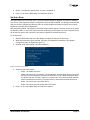
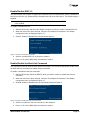
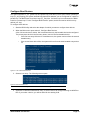
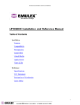
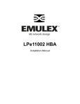
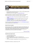
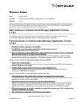
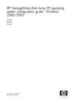
x86 BootBIOS
Version 1.70a1
User Manual
Copyright© 2005 Emulex Corporation. All rights reserved worldwide. No part of this document may be reproduced
by any means nor translated to any electronic medium without the written consent of Emulex Corporation.
Information furnished by Emulex Corporation is believed to be accurate and reliable. However, no responsibility is
assumed by Emulex Corporation for its use; or for any infringements of patents or other rights of third parties which
may result from its use. No license is granted by implication or otherwise under any patent or patent rights of Emulex
Corporation.
Emulex and LightPulse are registered trademarks, and AutoPilot Installer, AutoPilot Manager, BlockGuard,
FibreSpy, HBAnyware, InSpeed, MultiPulse and SBOD are trademarks, of Emulex Corporation. All other brand or
product names referenced herein are trademarks or registered trademarks of their respective companies or
organizations.
Emulex provides this manual "as is" without any warranty of any kind, either expressed or implied, including but not
limited to the implied warranties of merchantability or fitness for a particular purpose. Emulex Corporation may
make improvements and changes to the product described in this manual at any time and without any notice. Emulex
Corporation assumes no responsibility for its use, nor for any infringements of patents or other rights of third parties
that may result. Periodic changes are made to information contained herein; although these changes will be
incorporated into new editions of this manual, Emulex Corporation disclaims any undertaking to give notice of such
changes.
x86 BootBIOS User Manual
Page ii
Table of Contents
Introduction.............................................................................................................. 1
Compatibility...................................................................................................... 1
Prerequisites ..................................................................................................... 1
Topology............................................................................................................ 1
Things to Know Before You Download .............................................................. 2
Known Issues .................................................................................................... 3
Files Included in This Release........................................................................... 3
Loading x86 BootBIOS ............................................................................................ 4
Load x86 BootBIOS Using lputilnt ..................................................................... 4
Load x86 BootBIOS Using elxcfg ...................................................................... 5
Load x86 BootBIOS Using lputil ........................................................................ 6
Loading x86 BootBIOS Using lp6dutil................................................................ 6
Enable x86 BootBIOS on HBAs Using the BIOS Utility ..................................... 8
Configuration ......................................................................................................... 10
Introduction ..................................................................................................... 10
Start the BIOS Utility........................................................................................ 10
Adapter Configuration Menu Summaries......................................................... 11
Change the Default AL_PA.............................................................................. 12
Change the PLOGI Retry Timer ...................................................................... 13
Change Topology ............................................................................................ 13
Enable/Disable the Spinup Delay .................................................................... 14
Set Auto Scan ................................................................................................. 15
Enable/Disable EDD 3.0.................................................................................. 16
Enable/Disable the Start Unit Command ......................................................... 16
Enable/Disable the Environment Variable........................................................ 17
Enable/Disable Auto Sector Format Select...................................................... 17
Configure Boot Devices................................................................................... 18
Install Windows 2000 Server on a Fibre Channel Disk .................................... 19
Use Multi-Boot BIOS ....................................................................................... 20
Troubleshooting x86 BootBIOS ............................................................................. 21
The x86 BootBIOS Message Does Not Appear on Bootup .............................. 21
Retry This Adapter Message ........................................................................... 21
The .prg File Fails During Downloading........................................................... 21
x86 BootBIOS User Manual
Page iii
Introduction
x86 BootBIOS works with the existing basic input output system (BIOS) on x86 systems. x86 BootBIOS
allows you to designate a Fibre Channel drive as the boot drive.
Compatibility
•
x86 BootBIOS is compatible with the following Emulex® Fibre Channel Peripheral Component
Interconnect (PCI) host bus adapters (HBAs):
•
LP10000ExDC and LP1050Ex (minimum firmware version 1.90a4)
•
LP10000DC, LP10000, LP1050 and LP1050DC (minimum firmware version 1.80a1)
•
LP9802DC, LP9802 and LP982 (minimum firmware version 1.00a4)
•
LP9402DC, LP9002DC, LP9002L, LP9000 and LP952 (minimum firmware version
3.82a1)
•
LP8000 and LP8000DC (minimum firmware version 2.81)
•
LP850 (minimum firmware version 1.01)
•
Supports multiple HBAs. Multiple HBAs on different systems in a loop must be connected
through one or more hubs. For multi-adapter support, use the FC Port driver for Windows NT
version 1.24 or above.
•
Supports multi-LUNs: up to 256 LUNs. A maximum of 256 LUNs is supported (LUN 0 through
255) per target ID (D_ID or AL_PA). These 256 LUNs can be scanned in different stages using
the BIOS utility. However, only 64 entries can be seen during BIOS initialization.
•
Supports Multi-boot: complies with BIOS Boot Specification (BBS).
•
Supports Enhanced Disk Drive Services (EDD): supports both EDD 3.0 and EDD 2.1 depending
on how the BIOS utility is configured.
Prerequisites
x86 BootBIOS requires the following:
•
Have a system with a compatible HBA installed.
•
Enough free space on the intended Fibre Channel target disk to hold all system files and the
swap slice of the current local boot disk.
Topology
•
Supports FC-AL (Fibre Channel arbitrated loop – private and public) and fabric point-to-point
topologies. Options in auto topology:
•
Auto topology (default): Loop first, if it fails, it will try fabric point-to-point
•
Auto topology: fabric point-to-point first, if it fails, it will try loop
•
FC-AL (loop) only
•
Fabric point-to-point only
•
For FC-AL topology, the HBA's AL_PA, PCI bus number and PCI device number can be viewed
on the welcome screen or in the BIOS utility menu. In this way, you can know exactly which HBA
is in which PCI slot in the system.
•
For fabric point-to-point or public loop topology, the S_ID (source ID), PCI bus number and PCI
device number are displayed on the screen.
x86 BootBIOS User Manual
Page 1
•
In a fabric environment, the maximum number of devices (D_ID) is 90 when configuring the boot
device in the BIOS utility.
•
On a private loop, the maximum number of devices (AL_PA) is 99 when configuring the boot
device in the BIOS utility.
Things to Know Before You Download
•
As a measure of protection, ensure that critical files on your local boot disk are backed up.
•
The .PRG files included in this release contain only the boot code overlay (no firmware).
•
If your system does not support Multi-boot (BBS), the boot disk (drive C:) is determined by the
first configured boot entry (primary boot entry). If you want to configure the second HBA, do not
configure any boot entry on the first HBA.
Example 1:
Adapter 1: boot_entry0, boot_entry1
Adapter 2: boot_entry2, boot_entry3
Drive C: boot_entry0
Example 2:
Adapter 1:
Adapter 2: boot_entry2, boot_entry3
Drive C: boot_entry2
•
If your system supports Multi-boot (BBS), the boot disk (drive C:) is the first entry in Multi-boot
on the system BIOS setup menu. The entries that are exported to the Multi-boot menu are
determined by the list of configured boot entries in the BIOS utility. For example:
Adapter 1: boot_entry0, boot_entry1
Adapter 2: boot_entry2, boot_entry3
The order of boot entries that are exported to the Multi-boot is:
boot_entry0, boot_entry1, boot_entry2 and boot_entry3.
However, Multi-boot can overwrite this order by:
boot_entry2, boot_entry0, boot_entry1 and boot_entry3.
In this case, Drive C: is boot_entry2.
•
You may have any number of HBAs in your system and these can be any combination of
compatible HBAs. However, only the first 64 HBAs can be configured as boot HBAs. Any HBA
after the 64th one will not be visible during the boot process.
•
If the HBA’s BootBIOS bootup message is not enabled (or activated), this HBA will not be
configured. Also, a "No BIOS support" message appears next to the HBA in the BIOS utility
when you boot the system. You must enable (activate) the BootBIOS bootup message in order
to make the HBA bootable.
•
If there are any hardware changes such as replacing drives or re-configuring a fabric switch
environment, be sure to re-configure the BIOS using the BIOS utility.
•
Boot Fail Over: Sixty-four boot entries can be configured – if the first boot entry fails, the system
boots from the second configured boot entry, and so on.
•
If the message "Retry this Adapter" appears during BIOS scanning, check the hardware
configuration or re-configure the BIOS using the BIOS utility.
x86 BootBIOS User Manual
Page 2
Known Issues
The following issue has been reported at the time of publication.
•
BIOS Downloading Issue: This version of BIOS has increased in size from 44 KB to 49 KB. As a
result, it might fail during download of the BIOS .prg file. To correct this problem, first download
the firmware .awc file (without BIOS image, for example dd390a7.awc), then download the BIOS
.prg file.
Files Included in This Release
This kit includes the following files:
File Name
Description
readme.txt
Release notes for x86 BootBIOS version 1.70a1
tb170a1.prg
LP10000DC, LP10000 and LP10000ExDC x86 BootBIOS
mb170a1.prg
LP1050Ex, LP1050DC and LP1050 x86 BootBIOS
hb170a1.prg
LP9802DC and LP9802 x86 BootBIOS
lb170a1.prg
LP982 x86 BootBIOS
cb170a1.prg
LP9402DC, LP9002DC, LP9002L and LP9000 x86 BootBIOS
rb170a1.prg
LP952L x86 BootBIOS
db170a1.prg
LP8000 and LP8000DC x86 BootBIOS
qb170a1.prg
LP850 x86 BootBIOS
x86 BootBIOS User Manual
Page 3
Loading x86 BootBIOS
Before you update x86 BootBIOS, decide which utility to use. Emulex offers a variety of utilities that you
can use to update x86 BootBIOS. The utilities that you can use depend on your operating system and, in
some cases, driver:
Operating System
lputilnt*
elxcfg**
X
X
Windows
lputil
lp6dutil***
X
Linux
X
X
Solaris (x86 system)
X
X
* SCSIport Miniport and Storport Miniport drivers only
** FC Port driver only
*** Requires DOS (will not run in a DOS window)
After you decide which utility to use, see the appropriate update procedures:
•
lputilnt: See Load x86 BootBIOS Using lputilnt on page 4.
•
elxcfg: See Load x86 BootBIOS Using elxcfg on page 5.
•
lputil: See Load x86 BootBIOS Using lputil on page 6.
•
lp6dutil : See Loading x86 BootBIOS Using lp6dutil on page 6.
Load x86 BootBIOS Using lputilnt
Prerequisites
•
One of the following drivers is installed and loaded properly:
•
SCSIport Miniport driver for Windows Server 2003, Windows 2000 Server or Windows
NT.
•
Storport Miniport driver for Windows Server 2003.
•
lputilnt is installed properly.
•
The x86 BootBIOS file has been downloaded from the Emulex Web site and extracted to a folder
on your local hard drive.
•
The system is in a state in which this type of maintenance can be performed:
•
I/O activity on the bus has been quieted.
•
Cluster software, or any other software that relies on the HBA to be available, has been
stopped or paused.
To load x86 BootBIOS using lputilnt:
1. Start lputilnt: Click Start, Programs, Emulex and lputilnt.
2. Select the desired HBA.
3. Select Firmware Maintenance from the Category list.
4. Click Download and locate the new x86 BootBIOS file.
5. Click Open. The new boot code is transferred to flash ROM.
x86 BootBIOS User Manual
Page 4
6. Click Boot Bios Firmware (Figure 1).
Figure 1: lputilnt, Program Type list.
7. If the Disable button appears, the boot code is already enabled; skip to step 9. Otherwise,
continue with step 8.
8. Click Enable; the Enable button changes to Disable and the letter W appears to the left of "Boot
Bios Firmware" in the Program Type list. This indicates that x86 BootBIOS is in use.
9. Continue by enabling x86 BootBIOS on HBAs (page 8).
Load x86 BootBIOS Using elxcfg
Prerequisites
•
The FC Port driver for Windows Server 2003, Windows 2000 Server or Windows NT is installed.
•
elxcfg is installed properly.
•
The x86 BootBIOS file has been downloaded from the Emulex Web site and extracted to a folder
on your local hard drive.
•
The system is in a state in which this type of maintenance can be performed:
•
I/O activity on the bus has been quieted.
•
Cluster software, or any other software that relies on the HBA to be available, has been
stopped or paused.
To load x86 BootBIOS using elxcfg:
1. Start elxcfg: Click Start, Programs, Emulex and elxcfg.
2. Locate and select an HBA from the Available Adapters list (Figure 2).
Figure 2: elxcfg Utility, Available Adapters List
3. Select Download Firmware from the Tools menu. A browse window is displayed.
4. Browse to the folder into which you extracted the x86 BootBIOS file and select the file.
5. Click Open. The file is downloaded, and a confirmation window is displayed.
6. Click OK to close the confirmation window.
7. Enable the x86 BootBIOS Bootup Message Using lp6dutil, if necessary (page 6).
8. Continue by enabling x86 BootBIOS on HBAs (page 8).
x86 BootBIOS User Manual
Page 5
Load x86 BootBIOS Using lputil
Prerequisites
•
The Emulex driver for Linux or Solaris is installed and loaded properly.
•
The x86 BootBIOS file has been downloaded from the Emulex Web site and extracted to a
directory on your local hard drive.
•
lputil is installed properly.
To load x86 BootBIOS using lputil:
1. Start lputil by entering the complete path. The path in the example reflects the default installation
path. If the installation path was modified, adjust the command appropriately.
/usr/sbin/lpfc/lputil
2. From the Main menu, enter 3, Firmware Maintenance.
3. From the list that appears, choose the HBA onto which you want to load x86 BootBIOS.
4. Enter 1, Load Firmware Image.
5. Enter the full path to the remote boot image file. The new boot code is transferred to flash ROM.
6. From the Firmware Maintenance menu, press 6, Boot BIOS Maintenance.
7. Press 1, Enable Boot BIOS, to enable the Boot message. (If item 1 is Disable Boot BIOS, the
BIOS message is already enabled.)
8. Continue by enabling x86 BootBIOS on HBAs (page 8).
Loading x86 BootBIOS Using lp6dutil
Prerequisites
•
The x86 BootBIOS file has been downloaded from the Emulex Web site and extracted to a
directory on your local hard drive.
All lp6dutil tasks can be performed using the graphical user interface (GUI) screen menus. All screens
require navigation and selection using the keyboard.
Note: You cannot start lp6dutil at the screen’s command prompt.
To load x86 BootBIOS using lp6dutil:
1. Start lp6dutil:
a. Boot up your system with DOS.
b. From the directory where the lp6dutil.exe file resides, enter the following command:
lp6dutil
2. Press and hold down the < Alt> key and press L. The flash menu is displayed.
Figure 3: lp6dutil, Flash Menu
x86 BootBIOS User Manual
Page 6
3. Press D. The Download Image window is displayed.
Figure 4: lp6dutil, Download Image Window
4. Specify the location of the image file and the adapter to be updated.
5. Specify the Reset After Download setting.
•
Defaults to Yes. If you are updating a single file to one HBA, keep the default setting.
•
If you are updating several HBAs or several files to one HBA, select No.
6. Tab to the OK button and press <Enter>. The screen closes and the load process begins.
Various steps of the download process are displayed along with the results of the download
(success or error).
7. Press and hold down the <Alt> key and press L. The flash menu is displayed (Figure 3).
8. Press B. The Change Boot BIOS State window is displayed. This window is used to change the
x86 BootBIOS state for an adapter.
Figure 5: lp6dutil, Change Boot BIOS State Window - Disabled BootBIOS Message
9. Highlight the HBA in the Adapters list.
10. Highlight the x86 BootBIOS image in the BIOS Images list.
11. Tab to Change and press <Enter>. The BootBIOS message is enabled for the selected HBA.
12. Tab to OK and press <Enter> to close the window.
13. Continue by enabling x86 BootBIOS on HBAs (page 8).
x86 BootBIOS User Manual
Page 7
Enable x86 BootBIOS on HBAs Using the BIOS Utility
To use any of its features, x86 BootBIOS must be enabled on at least one installed HBA.
Prerequisites
•
x86 BootBIOS is loaded on the HBA.
•
The BIOS message is enabled.
To enable BootBIOS on the HBA:
1. Boot the system.
2. Press <Alt E> immediately (within five seconds) when the x86 BootBIOS message is displayed
to start the BIOS utility. A menu displays a list of HBAs (Figure 6).
Figure 6: BIOS Utility, HBA Listing
3. Select the HBA by entering the appropriate number.
4. The main configuration menu is displayed (Figure 7).
Figure 7: BIOS Utility, Main Configuration Menu
x86 BootBIOS User Manual
Page 8
5. Press 2 to configure the HBA. The adapter configuration menu is displayed (Figure 8).
Figure 8: BIOS Utility, Adapter Configuration Menu
6. Press 1 to Enable or Disable BIOS.
7. Exit the BIOS utility and reboot the system. After x86 BootBIOS is enabled on the HBAs, refer to
the Configuration section for information on other adapter configuration menu options.
x86 BootBIOS User Manual
Page 9
Configuration
Introduction
The BIOS utility allows you to change HBA parameters (such as topology, PLOGI retry timer and auto scan
setting) and configure boot devices.
•
Default settings are acceptable for most installations.
•
In the BIOS utility, press <d> to reset the selected adapter to default values.
•
The default topology is auto topology with loop first. For FC-AL, each HBA has a default AL_PA
of 01 (Hex). Change this topology setting, if necessary, before configuring boot devices.
•
All HBAs or boot drives can be configured to other AL_PAs than their default values.
•
If more than one HBA is in the system with the same PCI bus number, and each has a boot drive
attached, the first PCI-scan HBA will be the boot HBA. The first HBA is usually in the lowest PCI
slot in the system. This information can be viewed from the BIOS utility.
Start the BIOS Utility
Prerequisites
•
x86 BootBIOS must be loaded and the bootup message enabled on at least one of the host bus
adapters in your system to run the BIOS Utility.
To start the BIOS utility to configure your adapters:
1. Turn on the computer.
2. Press <Alt E> immediately (within five seconds) when the x86 BootBIOS message displays to
start the BIOS Utility. An HBA listing is displayed.
3. Select the adapter to configure by entering the appropriate number.
Figure 9: BIOS Utility, HBA Listing
Note: If the x86 BootBIOS message does not appear, enable this message. See Enable
x86 BootBIOS on HBAs Using the BIOS Utility on page 8 for more information.
x86 BootBIOS User Manual
Page 10
4. Select 1 to configure boot devices or 2 to configure the adapter’s parameters.
Figure 10: BIOS Utility, Main Configuration Menu
5. If you select to configure the adapter’s parameters, the adapter configuration menu is displayed.
Figure 11: Adapter Configuration Menu
Adapter Configuration Menu Summaries
1. Enable or Disable BIOS. Enable or disable x86 BootBIOS on the selected adapter. To use any
of its features, x86 BootBIOS must be enabled on at least one installed HBA. See Enable x86
BootBIOS on HBAs Using the BIOS Utility on page 8 for more information.
2. Change Default ALPA of this adapter. This option applies only to arbitrated loop (FC-AL). The
factory default is 01 (hexadecimal). See Change the Default AL_PA on page 12 for more
information.
3. Change PLOGI Retry Timer(+ Advanced Option+). Set the interval for the port log in retry
timer. The factory default is No PLOGI Retry: 0 msec. See Change the PLOGI Retry Timer on
page 13 for more information.
4. Topology Selection(+Advanced Option+). If it is necessary to change the topology, do so
before you configure boot devices. See Change Topology on page 13 for more information.
5. Enable or Disable Spinup Delay(+ Advanced Option+). Enable or disable the spinup delay.
The factory default is disabled. See Enable/Disable the Spinup Delay on page 14 for more
information.
x86 BootBIOS User Manual
Page 11
6. Auto Scan Setting(+ Advanced Option+). Enable the first device in the boot entry list to issue
a Name Server Inquiry. The factory default is disabled. See Set Auto Scan on page 15 for more
information.
7. Enable or Disable EDD 3.0(+ Advanced Option+). Enable or disable the Enhanced Disk
Driver (EDD) option, which is available on Itanium 64-bit servers only. The factory default is
disabled. See Enable/Disable EDD 3.0 on page 16 for more information.
8. Enable or Disable Start Unit Command(+ Advanced Option+). You must know the specific
LUN to issue the SCSI Start Unit Command. The factory default is disabled. See Enable/Disable
the Start Unit Command on page 16 for more information.
9. Enable or Disable Environment Variable(+ Advanced Option+). Enable or disable the ability
to set the boot controller order, if the system supports the environment variable. The factory
default is disabled. See Enable/Disable the Environment Variable on page 17 for more information.
A. Auto Sector Format Select(+ For MSA10000 Array use Only+). This option automatically
defines the boot sector (32-sector or 63-sector) of the target disk. The factory default is enabled.
See Enable/Disable Auto Sector Format Select on page 17 for more information.
Change the Default AL_PA
This option allows you to change the AL_PA (Arbitrated Loop Physical Address) of the selected adapter.
The default value of the AL_PA for the adapter BIOS is 01 (hex).
Note: This option applies only to arbitrated loop (FC-AL).
To change the default AL_PA:
1. Start the BIOS utility and select the adapter.
2. When the main menu opens select 2, Configure This Adapter's Parameters. The adapter
configuration menu is displayed (Figure 11).
3. Select 2, Change Default ALPA of this adapter.
Figure 12: Change Default ALPA Screen
4. Type the AL_PA, in hexidecimal notation, to which you want to change the default.
5. Press <x> to exit the BIOS utility and reboot the system.
Note: If the host adapter's AL_PA is changed, it will not show on the NVRAM AL_PA until
the system has been reset.
x86 BootBIOS User Manual
Page 12
Change the PLOGI Retry Timer
This option allows you to set the interval for the PLOGI (port login) retry timer. This option is especially
useful for Tachyon-based RAID arrays. Under very rare occasions, a Tachyon-based RAID array will reset
itself and the port will go offline temporarily in the loop. When the port comes to life, the PLOGI retry
interval scans the loop to discover this device. This default setting is No PLOGI Retry: 0 msec.
To set the interval for the PLOGI retry timer:
1. Start the BIOS utility and select the adapter.
2. When the main menu opens select 2, Configure This Adapter's Parameters. The adapter
configuration menu is displayed (Figure 11).
3. Select 3, Change PLOGI Retry Timer (+Advanced Option+).
Figure 13: Change the PLOGI Retry Timer Screen
4. Select the PLOGI retry timer interval. The time it takes for one PLOGI to scan the whole loop (if
126 AL_PA are on the loop) is shown below:
•
50 msec will take 5 to 6 seconds per device.
•
100 msec will take 12 seconds per device.
•
200 msec will take 22 seconds per device.
5. Press <x> to exit the BIOS utility and reboot the system.
Change Topology
This option allows you to select the topology for the host adapter.
Note: The default topology is auto topology with loop first. Change this topology
setting, if necessary, before configuring boot devices.
To select the host adapter topology:
1. Start the BIOS utility and select the adapter.
2. When the main menu opens select 2, Configure This Adapter's Parameters. The adapter
configuration menu is displayed (Figure 11).
x86 BootBIOS User Manual
Page 13
3. Select 4, Topology Selection (+Advanced Option+).
Figure 14: Topology Menu
4. Select the topology for the HBA:
•
Select 1 for auto topology with loop first.
•
Select 2 for auto topology with point-to-point first.
•
Select 3 for FC-AL.
•
Select 4 for fabric point-to-point.
5. Press <x> to exit the BIOS utility and reboot the system.
Enable/Disable the Spinup Delay
This option allows you to enable or disable the spinup delay. The factory default setting is disabled.
If at least one boot device has been defined, and the spinup delay is enabled, the BIOS searches for the
first available boot device.
•
If a boot device is present, the BIOS boots from it immediately.
•
If a boot device is not ready, the BIOS waits for the spinup delay and, for up to three additional
minutes, continues the boot scanning algorithm to find another Multi-boot device.
If no boot devices have been defined, and auto scan is enabled, then the BIOS waits for five minutes
before scanning for devices.
•
In a private loop, it attempts to boot from the lowest target AL_PA it finds.
•
In an attached fabric, it attempts to boot from the first target found in the NameServer data.
To enable or disable the spinup delay, do the following:
1. Start the BIOS utility and select the adapter.
2. When the main menu opens select 2, Configure This Adapter's Parameters. The adapter
configuration menu is displayed (Figure 11).
3. Select 5, Enable or Disable Spinup Delay (+Advanced Option+).
Figure 15: Enable or Disable Spinup Delay Screen
x86 BootBIOS User Manual
Page 14
4. Select 1 to enable the spinup delay, or press 2 to disable it.
5. Press <x> to exit the BIOS utility and reboot the system.
Set Auto Scan
This option allows you to set auto scan. The factory default setting is disabled. Auto Scan is available
only if none of the eight boot entries is configured to boot via DID or WWPN. It is strongly recommended
that you use the Configure Boot Devices menu to configure eight boot entries for fabric point-to-point,
public loop or private loop configurations.
With auto scan enabled, the first device will issue a Name Server Inquiry. The boot device will be either
the first DID, LUN 0, or not LUN 0 device returned, depending on the option you select. Only this device
will be the boot device and it will be the only device exported to the Multi-boot menu.
To set auto scan:
1. Start the BIOS utility and select the adapter for which you want to set auto scan.
2. When the main menu opens select 2, Configure This Adapter's Parameters. The adapter
configuration menu is displayed (Figure 11).
3. Select 6, Auto Scan Setting (+Advanced Option+).
Figure 16: Set Auto Scan Screen
4. Select the auto scan option:
•
Select 1 to disable auto scan.
•
Select 2 to scan for any first device. The first adapter issues a name server inquiry, and
the first D_ID from the inquiry becomes the boot device. The adapter attempts to log in
to a public loop first. If it fails, it logs in to a private loop. The first successfully scanned
device becomes the boot device. Only this device is exported to the Multi-boot menu.
•
Select 3 to scan for the first LUN 0 device.
•
Select 4 to scan for the first device that is not LUN 0.
5. Press <x> to exit the BIOS utility and reboot the system.
x86 BootBIOS User Manual
Page 15
Enable/Disable EDD 3.0
This option allows you to enable or disable the Enhanced Disk Drive (EDD) option, which is available on
Intel Itanium servers only. Enabling EDD 3.0 displays the path to the boot device. The default setting is
disabled.
Note: An x86 system could hang during Windows 2000 Server installation if EDD
3.0 is enabled.
To enable or disable EDD 3.0:
1. Start the BIOS utility and select the adapter for which you want to enable or disable EDD 3.0.
2. When the main menu opens select 2, Configure This Adapter's Parameters. The adapter
configuration menu is displayed (Figure 11).
3. Select 7, Enable or Disable EDD 3.0(+Advanced Option+).
Figure 17: Enable or Disable EDD 3.0 Screen
4. Select 1 to enable EDD 3.0, or press 2 to disable it.
5. Press <x> to exit the BIOS utility and reboot the system.
Enable/Disable the Start Unit Command
This command is used to issue the SCSI start unit command. You must know the specific LUN to issue
the SCSI start unit command.The default setting is disabled.
To enable or disable the start unit command:
1. Start the BIOS utility. Select the HBA for which you want to enable or disable the start unit
command.
2. When the main menu opens select 2, Configure This Adapter's Parameters. The adapter
configuration menu is displayed (Figure 11).
3. Select 8, Enable or Disable Start Unit Command(+Advanced Option+).
Figure 18: Enable or Disable Start Unit Command Screen
4. Select 1 to enable the start unit command, or 2 to disable it.
5. Press <x> to exit the BIOS utility and reboot the system.
x86 BootBIOS User Manual
Page 16
Enable/Disable the Environment Variable
This option allows you to set the boot controller order if the system supports the environment variable.
The default setting is disabled.
To enable or disable the environment variable:
1. Start the BIOS utility and select the adapter for which you want to enable or disable the
environment variable.
2. When the main menu opens select 2, Configure This Adapter's Parameters. The adapter
configuration menu is displayed (Figure 11).
3. Select 9, Enable or Disable Environment Variable(+Advanced Option+).
Figure 19: Enable or Disable Environment Variable Screen
4. Select 1 to enable the Environment Variable, or 2 to disable it.
5. Press <x> to exit the BIOS utility and reboot the system.
Enable/Disable Auto Sector Format Select
This option automatically defines the boot sector (32-sector or 63-sector) of the target disk. If there is no
partition on the target, the default boot sector format is 63 sectors. The default setting is enabled.
To enable or disable auto sector format select, do the following:
1. Start the BIOS utility and select the adapter for which you want to enable or disable the
command.
2. When the main menu opens select 2, Configure This Adapter's Parameters. The adapter
configuration menu is displayed (Figure 11).
3. Select A, Enable or Disable Auto Sector Format Select(+For MSA1000 Array Use Only+).
Figure 20: Enable or Disable Auto Sector Format Select Screen
4. Select 1 to enable auto sector format select, or 2 to disable it.
5. Press <x> to exit the BIOS utility and reboot the system.
x86 BootBIOS User Manual
Page 17
Configure Boot Devices
This option supports FC_AL: (public loop and private loop) and fabric point-to-point. When operating in
loop (FC_AL) topology, the system automatically determines whether you are configured for a public or
private loop. The BIOS looks for a fabric loop (FL_Port) first. If a fabric loop is not detected, the BIOS
looks for a private loop. For the "Configure Boot Devices" option, the 64 boot entries will be zero by
default (<d> key).
To configure boot devices:
1. Start the BIOS utility and select the adapter for which you want to configure boot devices.
2. When the Main menu opens select 1, Configure Boot Devices.
A list of 8 boot devices is shown. We recommend that only the bootable devices be configured.
The primary boot device is the first entry shown, and it is the first bootable device.
•
If the first boot entry fails due to a hardware error, the system can boot from the second
bootable entry.
•
If the second boot device fails, the system will boot from the third bootable entry and so
on.
Figure 21: List of Saved Boot Devices
3. Select a boot entry. The following screen opens:
Figure 22: Device Selection List
Note: We recommend that you select the drive with the lowest AL_PA as the boot device.
4. Select 00 to clear the selected boot entry, or select a device to configure booting via WWPN or
DID. If you select a device, you will be asked for the starting LUN.
x86 BootBIOS User Manual
Page 18
5. Enter the starting LUN. The starting LUN can be any number between 0 and 255.
Figure 23: LUN Listing
There are a possible 256 LUNs that can be defined per adapter, but the screen displays up to 16
consecutive LUNs at a time. In front of each entry, B#D or B#W specifies the boot entry number
and whether the device boots via DID or WWPN. For example, B1D means that boot entry one
will boot via DID. B2W means that boot entry two will boot via WWPN.
6. Select an entry. Another menu displays the following options:
1. Boot this device via WWPN
2. Boot this device via DID
7. Select the desired boot method.
If you select to boot the device via WWPN, the WWPN of the earlier selected entry is saved in
the flash. However, during the initial BIOS scan, it will issue a Name Server Inquiry GID_PN (Get
Port Identifier). Then, based on this DID, it will continue with the remainder of the scanning.
If you select to boot this device via DID, the earlier selected entry will be saved in the flash.
Install Windows 2000 Server on a Fibre Channel Disk
This procedure installs the Windows 2000 Server operating system onto a previously unformatted Fibre
Channel disk drive that is connected to the Emulex adapter.
Note: Your computer’s system BIOS may require that another controller take precedence
over the Emulex adapter during boot. If this occurs, you must disconnect or disable
the other adapter. This will allow you to configure and build your operating system on
the drive connected to the Emulex adapter.
To install Windows 2000 Server on a Fibre Channel disk:
1. From either the Emulex Web site or the CD-ROM that accompanies your Emulex product,
download the latest version of the Emulex driver for Windows 2000 Server.
2. Extract the driver files onto a formatted floppy disk.
3. Boot with the Windows 2000 Setup Media. (This procedure assumes you are using CD-ROM
medium. See Microsoft documentation for details.) The following message is displayed in the
status bar:
"Setup is detecting your hardware."
4. Press <F6>. The following message is displayed in the status bar:
"Specify additional storage driver"
x86 BootBIOS User Manual
Page 19
5. Press <S> to specify additional drivers.
6. Select Other.
7. Insert the floppy disk onto which you unzipped the Emulex driver in step 2.
8. If you downloaded the port driver, select a topology from the list and press <Enter>.If you
downloaded the miniport driver, select your adapter from the list and press <Enter>.
9. Follow the instructions to complete the Emulex installation.
10. Remove the floppy disk that contains the driver files.
11. Complete the Windows 2000 Server installation.
Use Multi-Boot BIOS
Multi-boot BIOS is in compliance with BIOS Boot Specification (BBS). The system must have a Multi-boot
system BIOS in order to take advantage of this feature. Multi-boot BIOS allows you to select any boot disk
in the system BIOS setup menu. The boot disk can be a Fibre Channel drive, a SCSI drive, an IDE drive or
a floppy drive. The Emulex BIOS supplies the first eight drives to the system BIOS menu. The Multi-boot
BIOS can override the Fibre Channel drive that is selected in the BIOS utility.
For example, the system has only eight Fibre Channel disks. The boot disk has AL_PA 02. However, you
can select AL_PA 23 in the system BIOS setup menu. The boot device will be the Fibre Channel disk
with AL_PA 23 instead of AL_PA 02, as is set in the BIOS utility.
If your system supports Multi-boot BBS, the boot disk (drive C) is the first entry in Multi-boot on the
system BIOS setup menu. The list of entries is determined by the list of configured boot entries in the
BIOS utility. For example:
Adapter 1: boot_entry0, boot_entry1
Adapter 2: boot_entry2, boot_entry3
The order of boot entries that is exported to Multi-boot (BBS) is
boot_entry0, boot_entry1, boot_entry2, and boot_entry3.
However, Multi-boot can overwrite this order by using the following command:
boot_entry2, boot_entry0, boot_entry1, and boot_entry3.
In this case, drive C is
boot_entry2.
x86 BootBIOS User Manual
Page 20
Troubleshooting x86 BootBIOS
There are circumstances in which your system may operate in an unexpected manner. This
Troubleshooting section explains several of these circumstances and offers one or more workarounds for
each situation.
The x86 BootBIOS Message Does Not Appear on Bootup
Situation: You want to access the x86 BootBIOS, but on bootup the x86 BootBIOS message does not
appear.
Resolution: Make sure that x86 BootBIOS has been loaded and enabled.
Retry This Adapter Message
Situation: The message "Retry This Adapter" appears during BIOS scanning.
Resolution: Check the hardware configuration or reconfigure the HBA BIOS using the BIOS utility.
The .prg File Fails During Downloading
Situation: The .prg file fails during downloading. The 1.70a1 version of the BIOS image is 48k, which
may cause the file to fail during downloading.
Resolution:
1. Download the firmware .awc file (without the BIOS image)
2. Download the BIOS image file.
Note: This problem may occur with LP9402DC, LP9002L, LP9002DC, LP9000,
LP952L, LP8000, LP8000DC or LP850 host bus adapters.
x86 BootBIOS User Manual
Page 21