1
G E OT H E R M A L H E AT I N G A N D C O O L I N G S Y S T E M S
7300 SW 44th. STREET
OKLAHOMA CITY • OK • 73179
(405) - 745-2920 • (800) - 299 - 9747
W W W. B RYA N T G E O. C O M
WATER-TO-WATER
SYSTEM DESIGN GUIDE
*BR402*
BR402
© Br yant, Inc. 2007
R E V. : 0 5 N o v, 2 0 0 7 D
W H AT E V E R I T TA K E S .
50YEW, 50PSW, & GSW
WATER-TO-WATER SYSTEMS
Water-to-Water System Design Guide
Bryant Geothermal Heat Pump Systems
Table of Contents
Revision Log
Water-to-Water System Design Guide
Unit Information
Part 1: System Overview
50YEW Water-to-Water Series
Why Hydronics.............................................................................................1
Features ..........................................................................................................70
Date
Page #
Description
05 Nov, 2007
77
Corrected Voltage Code
05 Nov, 2007
74
Corrected Source WPD & Load HE
12 Oct, 2007
All
First Published
Model Key .....................................................................................................72
Part II: Load Side Design
Unit Performance .....................................................................................74
Heat Gain / Loss Calculations ..............................................................6
Physical Data ...............................................................................................75
System Design & Selection .................................................................10
Unit Dimensions .......................................................................................76
Piping Design ...............................................................................................22
Electrical Data.............................................................................................77
Source & Load Pump Sizing ...............................................................24
Wiring Diagrams .......................................................................................78
Distribution Design..................................................................................24
Engineering Specifications....................................................................82
Radiant Floor Heating ............................................................................26
Baseboard Heating...................................................................................27
GSW Water-to-Water Series
Cast Iron Heating .....................................................................................28
Features ..........................................................................................................86
Fan Coils ........................................................................................................29
Model Key .....................................................................................................88
Snow Melt Applications ........................................................................30
Unit Performance .....................................................................................90
Physical Data ...............................................................................................97
Part III: Source Side Design
Unit Dimensions .......................................................................................98
System Selection .......................................................................................31
Electrical Data.......................................................................................... 100
Open Loop Design..................................................................................38
Wiring Diagrams .................................................................................... 101
Closed Loop Design ...............................................................................40
Engineering Specifications................................................................. 103
Closed Loop Instillation Guidelines................................................42
Part IV: Controls
50YEW Controls ......................................................................................56
Wiring Diagrams .......................................................................................59
Revision Log...............................................................Inside Back Cover
Bryant works continually to improve its products. As a result, the design and specifications of each product at the time for order may be changed without notice and may
not be as described herein. Please contact Bryant’s Customer Service Department at 1-405-745-2920 for specific information on the current design and specifications, and
placing orders. Statements and other information contained herein are not express warranties and do not form the basis of any bargain between the parties, but are merely
Bryant’s opinion or commendation of its products.
Bryant: Whatever It Takes.
Water-to-Water System Design Guide
Bryant Geothermal Heat Pump Systems
Part I: System Overview
WHY HYDRONICS?
According to Webster’s Dictionary, hydronic heating is “a system of
heating or cooling that involves the transfer of heat by a circulating
fluid (as water or vapor) in a closed system of pipes.” Because
water is the most efficient way to move thermal energy, a hydronic
system requires much less transport energy in the process and
takes up far less space. For example, a 1” [25mm] diameter pipe
can carry as much heat as a 10” x 19” [254 x 483 mm] rectangular
duct carrying hot air at 130°F [54°C]. In addition, the mass of
the ground loop [geothermal piping] and/or radiant floor piping
provides thermal storage, allowing the system to virtually ignore
large changes in outdoor temperatures. There is no storage benefit
in most HVAC systems.
and require a fan to circulate air through ductwork. Water-to-water
heat pumps heat water, allowing the design of a hydronic heating
system with the benefits of more efficient energy distribution,
lower operating costs and better comfort.
Fossil fuel furnaces and boilers are always less than 100% efficient.
Even the best systems are 95-96% efficient. Geothermal heat
pumps typically deliver 4 to 6 Watts of heat for every Watt
of energy consumed to run the compressor and ground loop
pump(s). In other words, for each Watt of energy used, 3 to 5
Watts of free energy from the ground is added to provide 4 to
6 Watts of energy to heat the space. The use of a high efficiency
water-to-water heat pump and a hydronic heating system is an
unbeatable combination.
Figure 1-1: Thermal Energy Comparison
Water-to-Water Heat Pumps
Bryant water-to-water heat pumps offer high efficiencies, advanced
features, extremely quiet operation and application flexibility. As
Bryant’s most adaptable products, water-to-water heat pumps may
be used for radiant floor heating, snow/ice melt, domestic hot water
heating, and many other hydronic heating applications.
Water Pipe
Air Duct
Hydronics systems, especially systems using radiant floor heating,
provide lower operating costs than forced air systems. More Watts
are used to circulate air through ductwork than to circulate water
through piping. For example, a typical 80% efficient natural gas
residential furnace with an output capacity of 80,000 Btuh [23.4
kW] uses an 850 Watt fan motor. For every Watt used to power
the fan, 94 Btuh [28 Watts] of heat is delivered via the forced air
ductwork. If a boiler or heat pump is used to generate heat, but
the heat is delivered through a radiant floor system, the pumping
power would typically be around 300-400 Watts, or 40% to 50%
of the air delivery system Watts, resulting in around 230 Btuh [67
Watts] of heat per Watt of pump power.
Radiant floor systems provide heat at occupant level. Hot air rises
to the ceiling (forced air systems), but heat always moves to cold
(radiant system). Therefore, a warm floor will heat objects in the
space, not the air directly, resulting in a space that feels warmer at
lower thermostat settings. Occupants will feel more comfortable,
and when the thermostat setting is lowered, the heat loss
decreases, resulting in better comfort at lower operating costs.
Hydronic heating systems can be combined with boilers or heat
pumps to generate hot water for radiant floor systems, baseboard
convectors, or radiators. Heat pumps are inherently more efficient
than fossil fuel (natural gas, oil, or propane) heating systems, and
geothermal heat pumps are more efficient than air-source heat
pumps, due to the mild heat source of the ground (as compared
to outdoor air temperatures). Water-to-air heat pumps heat the air,
Bryant’s exclusive double isolation compressor mounting system
provides the quietest water-to-water units on the market.
Compressors are mounted on rubber-grommets or vibration
isolation springs to a heavy gauge mounting plate, which is
then isolated from the cabinet base with rubber grommets for
maximized vibration/sound attenuation. A compressor discharge
muffler and additional sound attenuation materials further enhance
the quiet operation (50YEW models).
Bryant water-to-water heat pumps are available as heating only
(50YEW series) or with reversible operation for heating and
cooling (50PSW and GSW series). Figure 1-2 shows the simple
refrigerant circuit of the 50YEW series. With only four major
components, the refrigerant circuit is easy to understand and
troubleshoot if necessary.
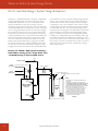
The 50YEW series includes a special high temperature scroll
compressor coupled with heat exchangers designed specifically
for water heating, which provides unmatched efficiencies and
performance. The evaporator is a coaxial (tube-in-tube) heat
exchanger that is capable of operation over a wide range
of temperatures, and is more rugged than other types of
evaporators, especially for open loop (well water) systems. The
condenser uses a close approach temperature brazed plate heat
exchanger that is designed for high temperature operation. This
combination of coaxial/brazed plate heat exchangers provides
the best combination of durability and efficiency. Bryant always
recommends coaxial heat exchangers for evaporators. Brazed
plate heat exchangers may be used for condensers when the unit
is not reversible.
Water-to-Water System Design Guide
1
Water-to-Water System Design Guide
Part I: System Overview
Figure 1-2: 50YEW Series Refrigerant Circuit
To/From
Ground
Loop
Source
Coaxial HX
(Evaporator)
Load
Compressor
To/From
Heating
Distribution
System
Brazed Plate HX
(Condenser)
TXV
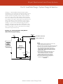
Figure 1-3: Reversible Water-to-Water Heat Pump, Heating Mode
Reversing
Valve
To/From
Ground
Loop
Load
Source
Coaxial HX
(Evaporator)
Compressor
To/From
Heating
Distribution
System
Coaxial HX
(Condenser)
TXV
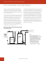
Figure 1-4: Reversible Water-to-Water Heat Pump, Cooling Mode
Reversing
Valve
To/From
Ground
Loop
Load
Source
Coaxial HX
(Condenser)
Compressor
Coaxial HX
(Evaporator)
TXV
2
Bryant: Whatever It Takes.
To/From
Chilled Water
Distribution
System
Bryant Geothermal Heat Pump Systems
Part I: System Overview
The 50YEW series compressors have a wide operating map, which
allows high temperature operation, up to 145°F [63°C] leaving
water temperature, even at 32°F [0°C] ground loop temperatures.
The ground loop heat exchanger [evaporator] is called the “Source”
heat exchanger in Bryant technical literature, and the heating
system heat exchanger is called the “Load” heat exchanger. The
terminology is not as important for heating only water-to-water
units, since the ground loop heat exchanger is always an evaporator,
but for reversible units, the evaporator and condenser change,
depending upon operating mode, heating or cooling.
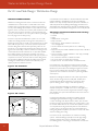
Figure 1-3 shows a Bryant reversible water-to-water unit. With the
addition of a reversing valve, the Source and Load heat exchangers
can change functions, depending upon the desired mode of
operation. In the heating mode, the “Load” heat exchanger
functions as the condenser, and the “Source” heat exchanger
functions as the evaporator.
In figure 1-4, the reversible water-to-water heat pump now
provides chilled water on the load side instead of hot water. The
load heat exchanger becomes the evaporator, and the source heat
exchanger becomes the condenser. Because the evaporator is
susceptible to freezing under adverse operating conditions (e.g.
failed pump, controls problem, etc.), a coaxial heat exchanger is
used on the load side for reversible units.
When selecting equipment for systems that require cooling, all
aspects of the system design should be considered. In many cases,
a separate water-to-air unit for forced air cooling is more cost
effective than using a chilled water / fan coil application due to the
complication in controls and seasonal change-over. For ground
loop applications, the water-to-water and water-to-air units can
share one ground loop system.
WATER-TO-WATER HEAT PUMP DESIGN
Design Temperatures
Various types of hydronic distribution systems have been used
successfully with geothermal heat pumps. Radiant floor systems
use relatively mild water temperatures, whereas baseboard
radiation and other types of heat distribution systems typically
use hotter water temperatures. When designing or retrofitting
an existing hydronic heating system, it is especially important to
consider maximum heat pump water temperatures as well as the
effect water temperatures have on system efficiency.
Heat pumps using R-22 refrigerant are not designed to produce
water above 130°F [54°C]. Some heat pumps with R-410A and
R-407C refrigerant are capable of producing water up to 145°F
[63°C]. Regardless of the refrigerant, the efficiency of the heat pump
decreases as the temperature difference (TD) between the heat
source (generally the earth loop) and the load water (the distribution
system) increases. Figure 1-5 illustrates the effect of source and load
temperatures on the system. The heating capacity of the heat pump
also decreases as the temperature difference increases.
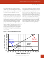
As the temperature difference increases, the Coefficient of
Performance (COP) decreases. When the system produces
130°F [54°C] water from a 30° [-1°C] earth loop, the TD is
100°F [55°C], and the COP is approximately 2.5. If the system is
producing water at 90° F [32°C], the TD is 60°F [33°C] and the
COP rises to about 5.0, doubling the efficiency.
If the water temperature of the earth loop is 90°F [32°C], and
the distribution system requires the same temperature, a heat
pump would not be needed. The system would operate at infinite
efficiency, other than the cost of pumping the water through the
Figure 1-5: COP vs TD
Water-to-Water System Design Guide
3
Water-to-Water System Design Guide
Part I: System Overview
distribution system. When using the various types of hydronic
heat distribution systems, the temperature limits of the geothermal
system must be a major consideration. In new construction, the
distribution system can easily be designed with the temperature
limits in mind. In retrofits, care must be taken to address the
operating temperature limits of the existing distribution system.
System Components
The efficiency, life expectancy and reliability of any hydronic heating
system depends upon how well the various components (heat pump,
distribution system, contols, etc.) work together. The heat pump must
be sized for the building loads; the earth loop must be sized to match
the building loads, ground conditions and climate; the circulating
pumps must be sized for the equipment, piping and ground loop. The
distribution system must be designed to heat and/or cool the building
comfortably. The components must then all be controlled effectively.
Building Heat Loss & Heat Gain
The design must begin with an accurate heating and/or cooling
load of the building. This is the most important step in the design
process. The sizing of the circulation pumps, the distribution
system and the earth loop are all derived directly from the sizing
of the equipment. Overestimating the heat loss or heat gain
means over sizing the system. The extra cost of the oversized
system is unnecessary. In fact, it may result in the selection of a
different type of system. If an oversized system is installed, it may
be inefficient and uncomfortable. If the system is undersized it will
not do an adequate job of heating and/or cooling the building.
Loop Design & Installation
Several factors determine the loop design for a specific installation.
The energy balance of the building determines how much heat is
taken from and rejected to the earth over the course of a year.
The climate determines the ambient earth temperatures and is a
major factor in the energy needs of the building. The earth itself
(the conductivity of the soil or rock and the moisture content) are
major factors in calculating the size of the loop. The earth can only
take (heat rejected) or give up (heat extracted/absorbed) a fixed
amount of Btu/hr [Watts] in a given area. The heat exchanger
must have sufficient surface area.
Many factors affect loop performance. Bryant offers training in
loop design and installation, and also provides residential and
commercial loop sizing software.
Controls
The control of a mechanical system determines how it functions. For
the building to work efficiently and comfortably, the building owner
or manager must understand system functionality and controls.
As Figure 1-5 shows, the efficiency of a heat pump is a factor
of the difference in temperature between the source and the
load. The heat loss or heat gain of a building varies with the
weather and the use of the building. As the outdoor temperature
decreases, the heat loss of the building increases. When the
ventilation system is operating, the heating or cooling loads
increase. As the occupancy increases, or more lighting is used, or
the solar gain increases, the cooling load increases. At times the
building may require virtually no heating or cooling.
The output of the hydronic heating distribution equipment,
whether it is baseboard radiation, fan coil units or radiant floor
heating equipment, is directly related to the temperature and
velocity of the water flowing through it. Baseboard radiation puts
out approximately 50% less heat with 110°F [43°C] water than
with 130°F [54°C] water. The same is true with fan coil units and
radiant floor heating. For example, if a system is designed to meet
the maximum heat loss of a building with 130°F [54°C] water,
it follows that if the heat loss is 50% lower (when the outdoor
temperature is higher), the load can be met with 110°F [43°C]
water. The lower water temperature greatly increases the COP of
the heat pump. Outdoor temperature reset, discussed in part IV of
this manual, is a very cost-effective method of matching the heating
(load side) water temperature with the heat loss of the building.
Other considerations for controls include heating/cooling
switchover, pump control, backup heat (if equipped), distribution
system or zone controls, and priority assignments (e.g. determining
if radiant floor heating or domestic hot water will take priority).
The 50YEW series includes internal controls, which makes system
installation much easier. Other Bryant water-to-water heat pumps
must be controlled via external controls.
The design of the loop itself (the size and type of pipe, the
velocity of the liquid circulating in the pipe and the spacing and
layout of the pipe) has a major effect on the heat absorption and
rejection capabilities of the loop. The depth (vertical) or trench
length (horizontal) of the loop must be calculated using IGSHPA
(International Ground Source Heat Pump Association) methods
or approved software. In addition, the type and percentage of
antifreeze can have a significant effect on loop performance.
The workmanship of the installation also plays a large role in the
effectiveness of the loop. All fusion joints must be done properly.
Vertical loops must be grouted properly for good contact with the
earth. Horizontal loops must be backfilled with material that will
not cut the pipe, and the soil should be compacted around the
pipe for good contact. All closed loop piping systems should be
hydrostatically pressure tested before burial.
4
Bryant: Whatever It Takes.
Bryant Geothermal Heat Pump Systems
Part I: System Overview
SUMMARY
Hydronic geothermal systems can be used very effectively in new
installations, as well as in many retrofit applications. Efficient systems
can be designed for residential, commercial and industrial applications.
To make a system as efficient as possible, it is important to follow
good design criteria. Some of the factors to consider are listed below:
• An accurate heat loss and heat gain must be calculated to
properly size the system.
• The system must meet the application requirements. In other
words, the design of the system must take into consideration
the type of distribution system and the needs of the customer.
For example, baseboard radiation designed for 180°F [82°C]
water should not be used with 130°F [54°C] water without
careful consideration and design analysis.
• The components of the system must be designed to work
together. The earth loop must be designed to work with the
heat pump; the pumping system must work effectively with the
earth loop and the heat distribution system; and the distribution
system must be chosen to work properly with the water
temperatures available from the heat pump.
• The system must be controlled to operate as efficiently
as possible. It is important to operate the system to take
variations in the building loads into account. For example,
the heat loss of the building is reduced when the outdoor
temperature climbs, and the temperature of the water
circulated through the distribution system can be lowered,
allowing the heat pumps to operate more efficiently. It is
possible to integrate the functions of the mechanical systems in
a building.
Water-to-Water System Design Guide
5
Water-to-Water System Design Guide
Part II: Load Side Design
HEAT LOSS / HEAT GAIN CALCULATIONS
Heat loss loss/gain calculations for any residential HVAC design
should be performed using standard industry practices. Bryant
accepted calculations include methods developed by ACCA (Air
Conditioning Contractors of America) used in Manual J, HRAI
(Heating, Refrigeration and Air Conditioning Institute of Canada)
and ASHRAE (American Society of Heating Refrigerating and Air
Conditioning Engineers). Light commercial load calculations should
be performed using ACCA Manual N or the ASHRAE method.
Other methods for load calculations outside of North America are
acceptable providing the methodology is recognized by the local
HVAC industry.
Heat Loss Calculations for Radiant Floor or Zoned
Baseboard Systems
A room-by-room calculation must be performed for all radiant
floor or zoned baseboard systems in order to determine the
design of the radiation system. Once the heat loss has been
calculated and the decision on flooring material has been made
for each room, the amount of radiant floor tubing, pipe spacing,
water temperature and layout can be determined, based upon the
Btuh/square foot [Watts/square meter] requirements. Similarly,
the amount of heat loss will allow the designer to determine the
length of baseboard convector required based upon the design
water temperature.
Outdoor design temperatures should be obtained from the
appropriate ACCA, ASHRAE or HRAI manual at the 99.6% condition
or local requirements, whichever is most severe. Indoor design
temperatures vary, based upon the type of system and customer
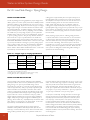
preference. Following are some minimum design guidelines:
System Type
100% Radiant Floor*
Mixed Radiant/Forced Air
Baseboard
Indoor
Minimum
Design Range
Indoor Design
65-70°F [18-21°C] 65°F [18°C]
68-72°F [20-22°C] 68°F [20°C]
68-72°F [20-22°C] 68°F [20°C]
*The nature of radiant floor heating tends to allow occupants
to feel the same comfort level with radiant floor heating at 65°F
[18°C] as with a forced air system at 70°F [21°C].
It is important to remember that a radiant floor system heats
objects, not the air. In turn, these objects radiate heat, which
heat people and furnishings to a comfortable temperature. Air
temperature remains near 65°F [18°C], and is approximately equal
from ceiling to floor. Forced air heating, by comparison, heats the
air, which heats the people and objects. Therefore, a higher air
temperature is required in order to bring people and objects up to
the same temperature as in a radiant heating system.
6
When calculating the heat loss of a structure, the nature of radiant
heating should be considered to allow for a more appropriately
sized system. As mentioned above, a thermostat setting of 65°F
[18°C] for a radiant floor system is comparable to a forced air
system with a thermostat setting of 70°F [21°C]. This principle
affects the heat loss in two ways:
1. The lower temperature difference [between indoor and
outdoor temperatures] causes the heat loss to be lower.
2. The lack of air movement lowers the infiltration rate of
the structure.
Following is an example of the differences in load calculations for
radiant floor systems and forced air systems:
System A: Forced Air System
ACCA Manual J heat loss calculation
2,000 sq. ft. [186 sq. meter] residential structure
Outside design temperature = 0°F [-18°C]
Indoor design temperature = 70°F [21°C]
Temperature difference = 70°F [39°C]
Air changes per hour = 0.60 AC/H
Heat loss = 50,000 Btu/hr [14,654 Watts]
System B: Radiant Floor System
ACCA Manual J heat loss calculation
2,000 sq. ft. [186 sq. meter] residential structure
Outside design temperature = 0°F [-18°C]
Indoor design temperature = 65°F [18°C]
Temperature difference = 65°F [36°C]
Air changes per hour = 0.50 AC/H
Heat loss = 44,423 Btu/hr [13,020 Watts]
When the characteristics of a radiant floor system are considered,
equipment sizing can be significantly impacted. In the example
above, the heat loss for the structure decreases by 5,577 Btu/hr
[1,635 Watts], or 11%. Industry estimates are as high as 20%.
However, Bryant encourages the use of load calculations at actual
temperature differences and infiltration rates for equipment sizing,
rather than “rules of thumb.”
Heat Gain Calculations
Most space cooling is accomplished through the use of forced air.
Heat gain calculations must be performed on a room-by-room or
zoned basis. Although load calculations for single zone systems
may consider the whole house or building as one zone, a room-byroom calculation will facilitate air duct sizing.
Outdoor design temperatures should be obtained from the
appropriate ACCA, ASHRAE or HRAI manual at the 0.4%
condition or local requirements, whichever is most severe. Indoor
design temperatures for cooling typically range from 70-78°F [2125°C], with most designed at 75°F [24°C].
Bryant: Whatever It Takes.
Bryant Geothermal Heat Pump Systems
Part II: Load Side Design / Equipment Sizing
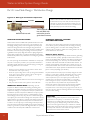
SIZING WATER-TO-WATER EQUIPMENT /
BUFFER TANKS
Water-to-Water Equipment Sizing
Water-to-water equipment sizing is dependent upon the type of
hydronic system application (load side – indoor) and the type of
ground loop system (source side – outdoor). Since the capacity
and efficiency of the water-to-water unit is directly related to the
entering source temperature, care must be taken to insure that
the unit will provide adequate capacity at design conditions. The
complexity of the ground loop sizing can be simplified with the
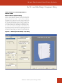
use of software, like Bryant’s GeoDesigner. GeoDesigner allows
the user to enter the heat loss/heat gain, the water-to-water unit
size, and the ground loop parameters. An analysis based upon bin
weather data allows the user to size the equipment/ground loop
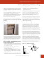
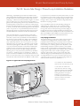
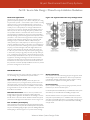
and obtain annual operating costs. Below is a typical screen shot.
Figure 2-1: GeoDesigner Heat Pump / Loop Sizing
Water-to-Water System Design Guide
7
Water-to-Water System Design Guide
Part II: Load Side Design / Equipment Sizing
Backup Heat
Just like water-to-air systems, which typically have some type
of backup heating capability, water-to-water systems can also
benefit from the use of supplemental heating to help lower initial
installation costs. Design temperatures are usually chosen for
1%. In other words, 99% of the time, the outdoor temperature
is above the design temperature. If the heat pump is designed to
handle 100% of the load, it is larger than required 99% of the time.
GeoDesigner can determine an economical balance point that will
allow the water-to-water unit to be downsized when a backup
boiler or water heater is used for supplemental heat.
For example, suppose a home in Chicago has a heat loss the same as
the example above [44,423 Btuh, 13,019 Watts]. One 50YEW010
unit has a heating capacity of approximately 10kW [33,000 Btuh] at
32°F [0°C] entering source (ground loop) temperature. According
to GeoDesigner, the water-to-water unit could handle the heating
load 98% of the time. A backup electric boiler would consume
about 326 kWh annually for back up heat [$33 per year at $0.10/
kWh]. Two 50YEW010 units could handle the heating load no
matter what the outdoor temperature is (100% heating – no backup
required). However, this combination would only save about 239
kWh per year [$24 per year at $0.10/kWh], yet the additional
installation cost for a second unit and significantly more ground loop
would never pay back in operating cost savings. In most cases, sizing
for 100% of the heating load is not cost effective.
Cooling
Cooling is not always desired with radiant heating systems. A
water-to-water heat pump system can provide chilled water to
ducted or non-ducted fan coil units. A reversible water-to-water
heat pump can provide chilled water to cool the building, as well
as hot water for the heating system. Buildings with fan coil units
can generally be retrofitted for cooling quite easily. The difficulty, as
mentioned in part I, is using existing fan coils for heating, especially
if they were originally sized for high water temperatures.
For optimal cooling and dehumidification, Bryant recommends a
separate water-to-air heat pump for cooling. Controls are much
simpler when a water-to-water unit is used for space heating
and/or domestic water heating, and a water-to-air unit is used for
cooling. Since the water-to-water and water-to-air units can share
one ground loop, the installation cost of using a water-to-air unit
for cooling is simply the incremental cost of the unit. Generally, no
additional ground loop is required (in Northern climates), and the
cost of the water-to-air unit is usually less than the cost of chilled
water/fan coil units, especially if the cost of additional piping/
valving/controls and labor is considered. The cost of a water-toair unit is approximately the same as a ductless mini split, and is
much more efficient. The advantages of geothermal heat pumps
for cooling (no outdoor unit, no refrigerant line sets, longevity, etc.)
should be considered when cooling is required.
the hydronic heating delivery system. A buffer tank is also required
for chilled water cooling applications if the water-to-water unit(s)
is more than 20% larger than the cooling load and/or multiple fan
coil units will be used. Water-to-water units sized for the cooling
load in applications with only ONE fan coil unit may be able
to operate without a buffer tank, but this would be an unusual
situation, since the cooling load is normally much smaller than
the heating load. The best approach is to plan for a buffer tank in
every application.
The size of the buffer tank should be determined based upon
the predominant use of the water-to-water equipment (heating
or cooling). For heating, buffer tanks should be sized at one U.S.
gallon per 1,000 Btuh [13 Liters per kW] of heating capacity at
the maximum entering source water temperature (EST) and the
minimum entering load water temperature (ELT), the point at
which the water-to-water unit has the highest heating capacity,
usually 50-70°F [10-21°C] EST and 80-90°F [26-32°C] ELT. For
cooling, buffer tanks should be sized at one U.S. gallon per 1,000
Btuh [13 Liters per kW] of cooling capacity at the minimum EST
and the maximum ELT, the point at which the water-to-water unit
has the highest cooling capacity, usually 50-70°F [10-21°C] EST and
50-60°F [10-16°C] ELT. Select the size of the tank based upon the
larger of the calculations (heating or cooling). The minimum buffer
tank size is 40 U.S. gallons [150 Liters] for any system.
Electric water heaters typically make good buffer tanks because of
the availability and relatively low cost. However, the water heater
must be A.S.M.E. rated (rated for heating) in order to qualify as a
buffer tank. Attention should be paid to insulation values of the
tank, especially when a buffer tank is used to store chilled water
due to the potential for condensation. A minimum insulation value
of R-12 [2.11 K-m2/W] is recommended for storage tanks.
CAUTION:
Maximum leaving water temperature of the 50YEW series
equipment is 145°F [63°C]. For domestic hot water tank
temperatures or heating buffer tank temperatures above
130°F [54°C], pump and pipe sizing is critical to insure that
the flow rate through the heat pump is sufficient to maintain
leaving water temperatures below the maximum temperature,
and to provide water flow rates within the ranges shown in
the performance section of this manual.
Buffer Tank Sizing / Application
All water-to-water units used in heating applications require a
buffer tank to prevent equipment short cycling and to allow
different flow rates through the water-to-water unit than through
8
Bryant: Whatever It Takes.
Bryant Geothermal Heat Pump Systems
Part II: Load Side Design / Equipment Sizing
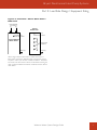
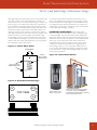
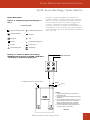
Figure 2-2: Connections – Electric Water Heater /
Buffer Tank
Hot/Cold Water
Connections
(1)
(2)
Typical
Buffer Tank
H
C
Connection for
Press Relief Valve
Connection for
Press Relief Valve
(1)
Typical Electric
Water Heater
(2)
Load & Source
Connections
(3)
(4)
Drain (3)
Drain (5)
When using an electric water heat as a buffer tank, there are
fewer water connections. Alternate piping arrangements may be
required to make up for the lack of water connections. Schematics
are shown in the next section. Above is an illustration showing the
water connection differences between a buffer tank and an electric
water heater.
Water-to-Water System Design Guide
9
Water-to-Water System Design Guide
Part II: Load Side Design / System Design & Selection
SYSTEM DESIGN
SYSTEM SELECTION
As mentioned in part I, hydronics applications offer a wide range
of application flexibility, so much in fact, that it is necessary to
narrow down the choices in order to start designing the system.
As with any heating and cooling design, there is never a perfect
solution, but rather a compromise between installation costs,
operating costs, desired features and comfort. Once the system is
selected, design of the distribution system, pumps, piping and other
components can be considered.
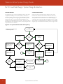
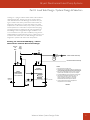
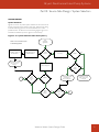
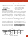
Figures 2-3a and 2-3b present system selection in flow chart
format for the load side of the water-to-water unit. There are
six piping schematics following the flow charts that illustrate each
of the possible choices. There are also two additional piping
schematics, one for alternate buffer tank piping, and one for using a
backup boiler for supplemental heat. To select the correct drawing,
begin in figure 2-3a, and finish the selection process in figure 2-3b.
Figure 2-3a: System Selection Flow Chart (Part 1)
Start
(Load Side Applications)
NOTE: Green arrows indicate Bryant
recommended applications.
Heating
System?
Radiant Floor
Chilled Water / Fan Coil
Chilled Radiant Floor
Use 50PSW or GSW series
Reversible Model
Buffer
Tanks?
(required)
Cooling
System?
No Cooling or Separate
Cooling System
1
Buffer tank for heating and
a separate buffer tank for
cooling
One buffer tank for both
heating and cooling
10
Baseboard Convection
Radiator
Fan Coil
Use 50YEW (high temp) or
50PSW/GSW ( med temp)
series
See drawing 2-5 (50PSW/
GSW + sep htg /clg buffer
tanks)
Cooling
System?
No Cooling or Separate
Cooling System
Use 50YEW (high temp)
series
See drawing 2-6 (50PSW/
GSW + one htg /clg buffer
tank)
Bryant: Whatever It Takes.
Chilled Water / Fan Coil
Chilled Radiant Floor
High temp (50YEW) unit is
not reversible.
2
Bryant Geothermal Heat Pump Systems
Part II: Load Side Design / System Design & Selection
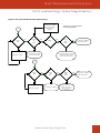
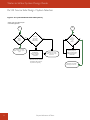
Figure 2-3b: System Selection Flow Chart (Part 2)
50YEW has integrated
controls. Choose 50YEW
(other choices are possible,
but not shown in
drawings).
1
NOTE: Green arrows indicate Bryant
recommended applications.
No
Buffer
Tank?
No
Buffer tank is required
Yes
Domestic
Hot
Water?
Yes
50YEW?
Yes
Indirect
Water
Heater?
No
Yes
See drawing 2-1 (50YEW +
Indirect Water Heater)
No
See drawing 2-3 (50YEW)
or drawing 2-4 (50PSW/ GSW)
Secondary Heat Exchanger / Pump
is required. See drawing 2-2 (50YEW
+ HX + Pump + Water Heater)
2
Buffer
Tank?
No
Buffer tank is required
Yes
Domestic
Hot
Water?
Yes
Indirect
Water
Heater?
No
See drawing 2-3 (50YEW)
Yes
See drawing 2-1 (50YEW +
Indirect Water Heater)
No
Secondary Heat Exchanger / Pump
is required. See drawing 2-2
(50YEW + HX + Pump +
Water Heat)
Water-to-Water System Design Guide
11
Water-to-Water System Design Guide
Part II: Load Side Design / System Design & Selection
System Descriptions
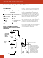
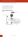
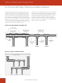
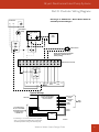
Drawing 2-1 – 50YEW Typical Load Piping Indirect Water Heater
/ No Cooling or Separate Cooling System: System #1 uses one
or more water-to-water units and a buffer tank for each unit.
Drawing 2-1 shows a typical piping arrangement for this system.
A thermistor mounted in an immersion well senses buffer tank
temperature, which allows the internal controls (50YEW units
only) to engage the water-to-water unit compressor, load pump
and source pump(s) when the tank temperature drops below
the set point, typically 120°F [49°C] or less. The radiant floor (or
baseboard, radiator, fan coil, etc.) system therefore is completely
isolated from the water-to-water unit. The controls for the
hydronic distribution system energize pumps and/or zone valves to
allow heated water in the buffer tank to flow through the heating
distribution system. Potable water is heated via an indirect water
heater, so that heating system water and potable water do not mix.
The 50YEW unit has an internal motorized valve, which allows
the load pump to send heated water to the buffer tank or the
indirect water heater. A thermistor mounted in an immersion well
senses DHW tank temperature, which allows the internal controls
(50YEW units only) to engage the water-to-water unit compressor,
load pump and source pump(s) when the DHW tank temperature
drops below the set point, typically 130°F [54°C]. If desired,
cooling is accomplished with a separate system.
Figure 2-4: Component Legend for Drawings 2-1 to
2-9
Component Legend
M
T
3-Way Valve - Manually Operated
Pressure Relief ("Pop-Off") Valve
3-Way Valve - Motorized
Check Valve
Mixing Valve
Union
Ball Valve
Pressure/Temperature (P/T) Port
Gate Valve
Circulator Pump
Pressure Reducing Valve
Heat Exchanger
Drawing 2-1: 50YEW Typical Load Piping Indirect Water Heater / No Cooling or Separate
Cooling System
P.R.V.
H
If heat exchanger
of indirect water
heater does not
have enough
mass, see
drawing 2-9
C
Indirect
Water Heater
Air Vent
Note 1
Exp
Tank
Thermistor
Note 2
To/From
Radiant Floor,
Radiator,
Baseboard,
or Fan Coil
Heating System
See drawings in section 3 for Source connections
H
IN
HTG
C
IN OUT
DHW HTG
OUT
DHW
OUT IN
M
Heating
Buffer Tank
50YEW
Unit
Note 3
Thermistor
Note 2
Load HX
(brz plt)
Source HX
(coaxial)
NOTES:
1. Place air vent at the highest point in the system. If
internal expansion tanks are installed, only an air
vent is required.
2. Thermistors should be installed in an immersion well.
Locate thermistor in the bottom half of the tank.
3. If electric water heat is used instead of buffer tank, see
drawing 2-7.
4. P/T (pressure/temperature) ports are internal for
50YEW units on load and source connections.
5. Other components (additional ball valves, unions, etc.)
may be required for ease of service. This drawing
shows only minimum requirements. Your specific
installation will dictate final component selections.
6. Buffer tank must be approved as a heating vessel.
7. Local code supercedes any piping arrangements or
components shown on this drawing.
03Oct07
12
Bryant: Whatever It Takes.
Bryant Geothermal Heat Pump Systems
Part II: Load Side Design / System Design & Selection
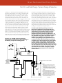
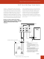
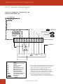
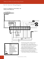
Drawing 2-2 – 50YEW Typical Load Piping Water Heater with
Secondary Heat Exchanger / No Cooling or Separate Cooling
System: System #2 uses one or more water-to-water units
and a buffer tank for each unit. Drawing 2-2 shows a typical
piping arrangement for this system. A thermistor mounted in
an immersion well senses tank temperature, which allows the
internal controls (50YEW units only) to engage the water-to-water
unit compressor, load pump and source pump(s) when the tank
temperature drops below the set point, typically 120°F [49°C]
or less. The radiant floor (or baseboard, radiator, fan coil, etc.)
system therefore is completely isolated from the water-to-water
unit. The controls for the hydronic distribution system energize
pumps and/or zone valves to allow heated water in the buffer
tank to flow through the heating distribution system. Potable
water is heated via a direct water heater (typically an electric
water heater) and a secondary heat exchanger (typically a brazed
plate heat exchanger), so that heating system water and potable
water do not mix. The 50YEW unit has an internal motorized
valve, which allows the load pump to send heated water to the
buffer tank or the secondary heat exchanger for heating potable
water. A thermistor mounted in an immersion well senses tank
Drawing 2-2: 50YEW Typical Load Piping Water Heater with Secondary Heat Exchanger /
No Cooling or Separate Cooling System
H
C
P.R.V.
Direct
Water Heater
Secondary
Pump
temperature, which allows the internal controls (50YEW units
only) to engage the water-to-water unit compressor, load pump
and source pump(s) when the tank temperature drops below
the set point, typically 130°F [54°C]. The use of a direct water
heat and secondary heat exchanger requires a pump between
the secondary heat exchanger and the water heater. The addition
of a pump contactor near the water heater will be necessary to
energize the pump any time the 50YEW load pump is energized
for potable water heating. If desired, the 50YEW controls allow
emergency water heating via electric elements if the 50YEW unit
is locked out. This requires a contactor at the water heater to
energize the electric elements when the heat pump is locked out.
Cooling is accomplished with a separate system.
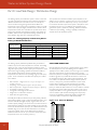
Secondary Heat Exchanger Sizing: Due to the
lower water temperatures associated with heat
pumps (as compared to 180-200°F [82-93°C] boiler
temperatures), heat exchanger sizing is critical.
Bryant recommends the use of sizing software
provided by the heat exchanger manufacturer. An
example is shown in figure 2-5. NOTE: Even though
the maximum leaving water temperature of the
50YEW series equipment is 145°F [63°C], some
room for piping changes, pump performance, and/
or pressure switch tolerance, should be considered
via slightly lower design temperatures (143°F [62°C]
is shown in figure 2-5 example). Refrigerant high
pressure switches typically have a tolerance of ± 15
psi [±1 Bar], potentially resulting in nuisance faults if
the switch tolerance is on the lower side of the range.
The compressor is rated for 145-149°F [63-65°C]
operation, but if the switch is marginal, a slightly
conservative design temperature will help avoid
nuisance faults.
Air Vent
Plate Heat
Exchanger
Note 2
Exp
Tank
Note 2
Thermistor
To/From
Radiant Floor,
Radiator,
Baseboard,
or Fan Coil
Heating System
See drawings in section 3 for Source connections
H
IN
HTG
C
IN OUT
DHW HTG
OUT
DHW
OUT IN
M
Heating
Buffer Tank
50YEW
Unit
Note 3
Thermistor
Note 2
Load HX
(brz plt)
Source HX
(coaxial)
NOTES:
1. Place air vent at the highest point in the system. If
internal expansion tanks are installed, only an air
vent is required.
2. Thermistors should be installed in an immersion well.
Locate thermistor in the bottom half of the tank.
3. If electric water heat is used instead of buffer tank, see
drawing 7.
4. P/T (pressure/temperature) ports are internal for
50YEW units on load and source connections.
5. Other components (additional ball valves, unions, etc.)
may be required for ease of service. This drawing
shows only minimum requirements. Your specific
installation will dictate final component selections.
6. Buffer tank must be approved as a heating vessel.
7. Local code supercedes any piping arrangements or
components shown on this drawing.
03Oct07
Water-to-Water System Design Guide
13
Water-to-Water System Design Guide
Part II: Load Side Design / System Design & Selection
CAUTION:
Maximum leaving water temperature of the 50YEW series
equipment is 145°F [63°C]. For domestic hot water tank
temperatures or heating buffer tank temperatures above 130°F
[54°C], pump and pipe sizing is critical to insure that the flow
rate through the heat pump is sufficient to maintain leaving water
temperatures below the maximum temperature, and to provide
water flow rates within the ranges shown in the performance
section of this manual.
SWEP INTERNATIONAL
v.1.5.6
SWEP North America, Inc.
3483 Satellite Blvd., Suite 210
Duluth, GA 30096
SWEP SSP CBE
HEAT EXCHANGER: B10Tx30H/1P (1” fittings)
SINGLE PHASE - Rating
Heat Pump
Customer: Example
Reference: 50YE W010 (60Hz) secondary HX for DHW
Date: 14SEP2007
DHW tank
DUTY REQUIREMENTS
Fluid Side 1
Fluid Side 2
Inlet temperature
Outlet temperature
Flow rate
SIDE 1
Propylene Glycol - Water (20.0 %)
Water
°F [°C]
: 143.00 [61.67]
°F [°C]
: 135.00 [57.22]
US gpm [l/m] : 12.00 [45.43]
Max. pressure drop
Thermal length
NTU
:
: 0.795
0.782
PHYSICAL PROPERTIES
Reference temperature
Dynamic viscosity
Dynamic viscosity - wall
Density
Specific heat capacity
Thermal conductivity
°F [°C]
cP
cP
lb/cuft
Btu/lb,°F
Btu/ft,h,°F
:
:
:
:
:
:
128.94 [53.86]
0.514
0.496
61.57
0.9991
0.3744
PLATE HEAT EXCHANGER
Heat load
Total heat transfer area
Heat flux
Log mean temperature difference
Overall H.T.C. (available/required)
Pressure drops - total
- in ports
Port diameter
Number of channels
Number of plates
Oversurfacing
Fouling factor
Btu/h [W]
sqrft [m 2 ]
Btu/h/sqrft
°F [°C]
Btu/sqrft,h,°F
psi [kPa]
psi [kPa]
in
:
:
:
:
:
:
:
:
:
:
%
:
sqrft,h,°F/Btu :
139.00 [59.44]
0.774
0.817
62.47
0.9699
0.3056
SIDE 2
125.00 [51.67]
132.87 [56.04]
12.00 [45.43]
46650 [13672]
9.34 [0.868]
4995
10.06 [5.59]
950/496
1.62 [11.17]
1.68 [11.58]
0.194 [1.34]
0.191 [1.32]
0.945
0.945
15
14
30
91
0.001
Note:
Disclaimer: Data used in this calculation is subject to change without notice. "SWEP may have patents, trademarks, copyrights or other intellectual property rights
covering subject matter in this document." "Except as expressly provided in any written license agreement from SWEP," "the furnishing of this document does not give
you any license to these patents, trademarks, copyrights, or other intellectual property."
DATE 14SEP07
14
PAGE 1 OF 1
Bryant: Whatever It Takes.
Sized to
deliver
130°F
[54°C]
at the
DHW
tank.
Bryant Geothermal Heat Pump Systems
Part II: Load Side Design / System Design & Selection
Figure 2-5: Example Secondary Heat Exchanger Sizing
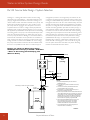
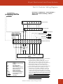
Drawing 2-3 – 50YEW Typical Load Piping / No DHW Heating
or Separate DHW System / No Cooling or Separate Cooling
System: System #3 uses one or more water-to-water units
and a buffer tank for each unit. Drawing 2-3 shows a typical
piping arrangement for this system. A thermistor mounted in
an immersion well senses tank temperature, which allows the
internal controls (50YEW units only) to engage the water-to-water
unit compressor, load pump and source pump(s) when the tank
temperature drops below the set point, typically 120°F [49°C] or
less. The radiant floor (or baseboard, radiator, fan coil, etc.) system
therefore is completely isolated from the water-to-water unit.
The controls for the hydronic distribution system energize pumps
and/or zone valves to allow heated water in the buffer tank to flow
through the heating distribution system. Potable water is heated
with a separate system. If desired, cooling is accomplished with a
separate system.
Drawing 2-3: 50YEW Typical Load Piping No DHW Heating or Separate DHW System / No
Cooling or Separate Cooling System
P.R.V.
Air Vent
Note 1
Cold Water Supply
To/From
Radiant Floor,
Radiator,
Baseboard,
or Fan Coil
Heating System
Exp
Tank
See drawings in section 3 for Source connections
Note 3
H
IN
HTG
C
IN
DHW
OUT
OUT DHW
HTG
OUT IN
M
Heating
Buffer Tank
50YEW
Unit
Note 4
Thermistor
Note 2
Load HX
(brz plt)
Source HX
(coaxial)
Water-to-Water System Design Guide
NOTES:
1. Place air vent at the highest point in the system. If
internal expansion tanks are installed, only an air
vent is required.
2. Thermistor should be installed in an immersion well.
Locate thermistor in the bottom half of the tank.
3. If DHW option is not used, DHW supply connection MUST
be plugged.
4. If electric water heat is used instead of buffer tank, see
drawing 2-7.
5. P/T (pressure/temperature) ports are internal for
50YEW units on load and source connections.
6. Other components (additional ball valves, unions, etc.)
may be required for ease of service. This drawing
shows only minimum requirements. Your specific
installation will dictate final component selections.
7. Buffer tank must be approved as a heating vessel.
8. Local code supercedes any piping arrangements or
components shown on this drawing.
03Oct07
15
Water-to-Water System Design Guide
Part II: Load Side Design / System Design & Selection
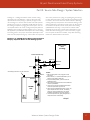
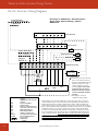
Drawing 2-4 – 50PSW/GSW Typical Load Piping / No DHW
Heating or Separate DHW System / No Cooling or Separate
Cooling System: System #4 uses one or more water-to-water
units and a buffer tank for each unit. Drawing 2-4 shows a typical
piping arrangement for this system. A thermistor mounted in an
immersion well senses tank temperature, which allows the waterto-water unit to engage the compressor, load pump and source
pump(s) when the tank temperature drops below the set point,
typically 120°F [49°C] or less. The radiant floor (or baseboard,
radiator, fan coil, etc.) system therefore is completely isolated from
the water-to-water unit. The controls for the hydronic distribution
system energize pumps and/or zone valves to allow heated water
in the buffer tank to flow through the heating distribution system.
Potable water is heated with a separate system. If desired, cooling
is accomplished with a separate system.
Drawing 2-4: 50PSW / GSW Typical Load Piping No DHW Heating or Separate DHW System / No
Cooling or Separate Cooling System
P.R.V.
Air Vent
Note 1
Cold Water Supply
Exp
Tank
To/From
Radiant Floor
P/T port (50PSW / GSW units only)
See drawings in section 3 for Source connections
IN
H
OUT
Heating
Buffer Tank
IN
NOTES:
1. Place air vent at the highest point in the system.
2. Aqua-stat should be installed in an immersion well.
Locate aqua-stat in the bottom half of the tank.
3. If electric water heat is used instead of buffer tank, see
drawing 2-7.
4. Other components (additional ball valves, unions, etc.)
may be required for ease of service. This drawing
shows only minimum requirements. Your specific
installation will dictate final component selections.
5. Buffer tank must be approved as a heating vessel.
6. Local code supercedes any piping arrangements or
components shown on this drawing.
50PSW
or GSW
Unit
Notes 2,3
Aqua-stat
16
OUT
C
Load HX
(coaxial)
Bryant: Whatever It Takes.
Source HX
(coaxial)
03Oct07
Bryant Geothermal Heat Pump Systems
Part II: Load Side Design / System Design & Selection
Drawing 2-5 – 50PSW/GSW Typical Load Piping - Chilled Water
Cooling System / Separate Heating & Cooling Buffer Tanks / No
DHW Heating or Separate DHW System: System #5 uses one
or more water-to-water units and two buffer tanks, one for heated
water, and one for chilled water. Drawing 2-5 shows a typical
piping arrangement for this system. An aqua-stat (well-mounted if
possible) in each tank senses tank temperature, which allows the
water-to-water unit to engage the compressor, load pump and
source pump(s) when the heating tank temperature drops below
the set point [typically 120°F [49°C] or less], or when the chilled
water tank temperature rises above the set point (typically 4550°F [7-10°C]). The radiant floor (or baseboard, radiator, fan coil,
etc.) heating system and the chilled water cooling system (typically
fan coil units) therefore are completely isolated from the waterto-water unit. The controls for the hydronic distribution system
energize pumps and/or zone valves to allow heated/chilled water
in the buffer tanks to flow through the heating/cooling distribution
systems. The motorized valve is used to switch between the
two tanks based upon heating or cooling season. Due to the
complexity of the controls, a manual seasonal changeover switch is
the best way to determine heated or chilled water operation. The
switch (typically a light switch) switches the unit reversing valve and
motorized valve. A reversible unit is required for this application
(50YEW is heating only – 50PSW/GSW units are reversible).
Potable water is heated with a separate system.
Drawing 2-5: 50PSW / GSW Typical Load Piping Chilled Water Cooling System / Separate Heating
and Cooling Buffer Tanks - No DHW Heating or
Separate DHW System
To/From
Radiant Floor
Air Vent
Note 1
Exp
Tank
H
C
Heating
Buffer Tank
Notes 2,3
Aqua-stat
Note 2
Note 4
P.R.V.
M
Cold Water Supply
To/From
Fan Coil Units
P/T port (50PSW / GSW units only)
See drawings in section 3 for Source connections
IN
H
OUT
OUT
IN
C
Chilled Water
Buffer Tank
50PSW
or GSW
Unit
Notes 2,3,5
Aqua-stat
Note 2
Load HX
(coaxial)
Source HX
(coaxial)
NOTES:
1. Place air vent at the highest point in the system.
2. Aqua-stat should be installed in an immersion well.
Locate aqua-stat in the bottom half of the tank.
3. If electric water heat is used instead of buffer tank, see
drawing 2-7.
4. Motorized valve to be activated by unit RV solenoid
coil (24VAC).
5. Chilled water tank must be insulated to avoid condensation.
6. Other components (additional ball valves, unions, etc.)
may be required for ease of service. This drawing
shows only minimum requirements. Your specific
installation will dictate final component selections.
7. Buffer tank must be approved as a heating vessel.
8. Local code supercedes any piping arrangements or
components shown on this drawing.
03Oct07
Water-to-Water System Design Guide
17
Water-to-Water System Design Guide
Part II: Load Side Design / System Design & Selection
Drawing 2-6 – 50PSW/GSW Typical Load Piping - Chilled Water
Cooling / Single Buffer Tank / No DHW Heating or Separate
DHW System: System #6 uses one or more water-to-water
units and a buffer tank for each unit. Drawing 2-6 shows a
typical piping arrangement for this system. Two aqua-stats (wellmounted if possible) sense tank temperature, one for heating and
one for cooling, which allows the water-to-water unit to engage
the compressor, load pump and source pump(s) when the tank
temperature drops below the set point (typically 120°F [49°C]
or less] in the heating mode, or when the tank temperature rises
above the set point [typically 45-50°F [7-10°C]) in the cooling
mode. The radiant floor (or baseboard, radiator, fan coil, etc.)
heating system and the chilled water cooling system (typically
fan coil units) therefore are completely isolated from the waterto-water unit. The controls for the hydronic distribution system
energize pumps and/or zone valves to allow heated/chilled water
in the buffer tank to flow through the heating/cooling distribution
systems. The motorized valves are used to switch between the
two distribution systems (and aqua-stats) based upon heating or
cooling season. Due to the complexity of the controls, a manual
seasonal changeover switch is the best way to determine heated
or chilled water operation. The switch (typically a light switch)
switches the unit reversing valve, motorized valves, and aqua-stats
(additional relays are required for determining heating/cooling
logic). A reversible unit is required for this application (50YEW
is heating only – 50PSW/GSW units are reversible). When using
one tank for both heated and chilled water, a buffer tank (not an
electric water heater) is recommended, since water heaters do not
have enough connections to facilitate all of the water connections
and the two well-mounted aqua-stats. Potable water is heated
with a separate system.
Drawing 2-6: 50PSW / GSW Typical Load Piping Chilled Water Cooling System / Single Buffer Tank
- No DHW Heating or Separate DHW System
P.R.V.
Cold Water Supply
To/From
Fan Coil Units
Air Vent
Note 4
Note 1
M
To/From
Radiant Floor
Exp
Tank
P/T port (50PSW / GSW only)
See drawings in section 3 for Source connections
IN
H
OUT
Heating / Chilling
Buffer Tank
IN
50PSW
or GSW
Unit
Notes 2,3
Heating
Aqua-stat
18
OUT
C
Cooling
Aqua-stat
Load HX
(coaxial)
Source HX
(coaxial)
Bryant: Whatever It Takes.
NOTES:
1. Motorized valves to be activated by unit RV solenoid
coil (24VAC).
2. Aqua-stat should be installed in an immersion well.
Locate heating aqua-stat in the bottom half of the tank.
Locate cooling aqua-stat in the top half of the tank.
3. Chilled water tank must be insulated to avoid condensation.
4. Place air vent at the highest point in the system.
5. Other components (additional ball valves, unions, etc.)
may be required for ease of service. This drawing
shows only minimum requirements. Your specific
installation will dictate final component selections.
6. Buffer tank must be approved as a heating vessel.
7. Local code supercedes any piping arrangements or
components shown on this drawing.
03Oct07
Bryant Geothermal Heat Pump Systems
Part II: Load Side Design / System Design & Selection
Drawing 2-7 – Alternate Buffer Tank (Electric Water Heater)
Typical Piping: A “true” buffer tank is the best approach for control
of a hydronic system using a heat pump. Tanks are usually well
insulated, and there are typically a number of water connections
(6 or more in many cases), so that plumbing is easier and water
flows are not restricted. However, due to the cost of buffer tanks,
some installers use an electric water heater for the buffer tank. An
electric water heater is much less expensive, but may not have
enough water connections, and may require external installation.
Drawing 2-7 may be used as an alternate piping schematic for
drawings 2-1 through 2-5 when an electric water heater is used.
Drawing 2-6 requires a buffer tank due to the need for two aquastats. If a water heater is used, it must be approved as a heating
vessel (A.S.M.E. approval in the U.S.).
Drawing 2-7: Alternate Buffer Tank (Electric
Water Heater) Typical Piping
Notes 1,2
Note 1
From Water-to-Water Unit
To Water-to-Water Unit
H
C
Radiant
Floor
System
Electric
Water Heater
(ASME Approved)
Note 3
Note 3
Thermistor or Aqua-stat
NOTES:
1. Not all components shown (expansion tank, air vent, etc.).
Drawing is for buffer tank connections only.
2. Pump not needed for 50YEW unit with internal load pump option.
3. Thermistor or aqua-stat should be installed in an immersion
well. If water heater does not have well, one of the
heating elements should be removed, and a well adapter
should be installed. Locate thermistor/aqua-stat in the
bottom half of the tank.
4. Other components (additional ball valves, unions, etc.)
may be required for ease of service. This drawing
shows only minimum requirements. Your specific
installation will dictate final component selections.
5. Buffer tank must be approved as a heating vessel.
6. Local code supercedes any piping arrangements or
components shown on this drawing.
03Oct07
Water-to-Water System Design Guide
19
Water-to-Water System Design Guide
Part II: Load Side Design / System Design & Selection
Drawing 2-8 – Piping for Backup Boiler (2nd Stage Heating):
Drawing 2-8 may be used for two different types of applications.
A boiler backup may be required because the water-to-water
unit lacks sufficient capacity at design conditions, or because the
hydronic heating distribution system requires hotter water than the
water-to-water unit can produce.
• Water-to-Water Unit Lacks Capacity: This type of system would
be used when the water-to-water unit has been sized to handle
less than 100% of the heating load. It is common practice to size
geothermal heat pump systems to handle 80-90% of the load
in order to lower equipment and ground loop requirements,
especially when the cooling load is less than the heating
load. In this case, the boiler control should be set at the same
temperature as the buffer tank (or the boiler can be controlled
by outdoor temperature). When the buffer tank begins to drop
in temperature (i.e. the heat pump can no longer maintain tank
temperature), the boiler comes on to make up the difference.
This type of system is excellent for retrofit installations, where an
existing boiler is in good operating condition.
• Distribution System Requires Hotter Water: This type of system
would be used when baseboard convectors, cast iron radiators or
fan coil units are already installed in a retrofit application. Since the
50PSW/GSW water-to-water units are only capable of producing
up to 130°F [54°C] leaving water temperature (50YEW waterto-water units can produce up to 145°F [63°C] leaving water
temperature), and the existing distribution system may require up
to 180°F [82°C] at design conditions, the water-to-water system
should be sized to handle the heating load up to the point where
hotter water is required (i.e. at the outdoor temperature balance
point). Typically, a properly sized water-to-water unit can handle
the load until the outdoor temperature drops to 20 to 30°F [-7
to -1°C]. At that point, the water-to-water unit compressor must
be disengaged (through the use of an outdoor thermostat or
other control means), and the boiler should be started. The water
delivered to the hydronic system now increases in temperature to
help satisfy the increased load.
Drawing 2-8: Piping for Backup Condensing Boiler
(2nd Stage Heating)
Notes 1,2
Note 1
From Water-to-Water Unit
To Water-to-Water Unit
H
C
Radiant
Floor
System
Note 3
OUT
Condensing
Boiler
Heating
Buffer Tank
Note 6
Note 4
Thermistor or Aqua-stat
IN
NOTES:
1. Not all components shown (expansion tank, air vent, etc.).
Drawing is for buffer tank connections only.
2. Pump not needed for 50YEW unit with internal load pump option.
3. Mixing valve and appropriate piping required on non-condensing
boilers (consult boiler manufacturer literature).
4. Thermistor or aqua-stat should be installed in an immersion
well. If water heater does not have well, one of the heating
elements should be removed, and a well adapter should be
installed. Locate thermistor/aqua-stat in the bottom half
of the tank.
5. Other components (additional ball valves, unions, etc.)
may be required for ease of service. This drawing
shows only minimum requirements. Your specific
installation will dictate final component selections.
6. Buffer tank must be approved as a heating vessel.
7. Local code supercedes any piping arrangements or
components shown on this drawing.
03Oct07
20
Bryant: Whatever It Takes.
Bryant Geothermal Heat Pump Systems
Part II: Load Side Design / System Design & Selection
Drawing 2-9 – Piping for Indirect Water Heaters with Insufficient
Heat Exchanger Mass: Drawing 2-9 may be used for indirect
water heaters that lack a heat exchanger of sufficient mass (see
figure 2-9 later in this section). Most indirect water heaters are
designed for 180°F [82°C] or hotter water. Using lower water
temperatures could cause the heat pump to short cycle and the
tank temperatures to remain below set point. When the piping
is arranged as shown in drawing 2-9, the mass is increased. The
disadvantages of this arrangement are higher installation costs,
more mechanical room space, and an additional pump (plus the
additional Watts associated with the pump). It is always best to use
an indirect water heater with more heat exchanger mass that is
designed for operation with lower water temperatures.
Drawing 2-9: Alternate DHW Piping - Indirect
Water Heater with Low Mass Heat Exchanger
Domestic
Hot
Water
Cold
Water
Supply
P.R.V.
Air Vent
Note 3
Note 4
To Water-to-Water Heat Pump
Exp
Tank
From Water-to-Water Heat Pump
H
H
C
C
NOTES:
Indirect
Water Heater
Direct
Water Heater
(optional backup
electric elements)
Notes 1,2
Aqua-stat
Note 2
Thermistor or aqua-stat
Note 1
Secondary Pump
1. Aqua-stat controls secondary pump.
2. Thermistor/aqua-stat should be installed in an immersion well.
Locate thermistor/aqua-stat in the bottom half of the tank.
3. Place air vent at the highest point in the system. If internal
expansion tanks are installed, only an air vent is required.
4. If optional 50YEW pump is used, this pump is not necessary.
5. Other components (additional ball valves, unions, etc.)
may be required for ease of service. This drawing
shows only minimum requirements. Your specific
installation will dictate final component selections.
6. Local code supercedes any piping arrangements or
components shown on this drawing.
03Oct07
Water-to-Water System Design Guide
21
Water-to-Water System Design Guide
Part II: Load Side Design / Piping Design
PIPING SYSTEM DESIGN
As with any heating and cooling application, proper design of the
delivery system is crucial to system performance, reliability and life
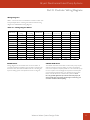
expectancy. Table 2-1 gives specifications for 3/4” [19 mm] and 1”
[25 mm] copper piping. Bryant recommends only type “L” straight
length copper tubing for connection between the water-to-water
unit and the buffer tank. In addition, all piping must be rated for
760 psi at 200°F [5.24 Pa at 93.3°C]. All piping must be insulated.
The smaller 3/4” [19 mm] tubing requires 1” [25 mm] diameter
insulation with a minimum 1/2” [13 mm] wall thickness. The larger
1” [25 mm] tubing requires 1-3/8” [35 mm] diameter insulation
with a minimum 1/2” [13 mm] wall thickness. The smaller 3/4”
[19 mm] tubing may be used on water-to-water units up to the
50YEW008 /50PSW008 / GSW036 with a maximum of 25 ft. [7.6
m] one-way and 8 elbows. The larger 1” [25 mm] tubing may be
used on water-to-water units up to the 50YEW012 / 50PSW012
/ GSW060 with a maximum of 25 ft. [7.6 m] one-way and 8
elbows. Refer to ASTM 388 for detailed information. Local codes
supersede any recommendations in this manual.
melting point of approximately 361-421°F [183-216°C], and is
typically applied using a propane torch. Proper flux is required.
An acetylene torch may be used, but care must be taken not to
overheat the piping, which can cause the material to become
brittle. Solder type 95/5 1/8” [3.2 mm] diameter solder has
melting point of approximately 452-464°F [233-240°C], and is
typically applied using a map gas torch (propane will work). Proper
flux is required. An acetylene torch may be used, but care must be
taken not to overheat the piping, which can cause the material to
become brittle.
When preparing copper joints for soldering, tubing should be
cut square, and all burrs must be removed. Do not use dented
or pitted copper. Clean the inside of the tubing with a brush;
clean the outside with emery cloth approximately 1/2” [13 mm]
from the end of the fitting. Debris in the system could cause
pump failure or corrosion. Do not put the fitting in a bind before
soldering. Flux should be applied as a thin film. Excess flux will
end up in the circulating fluid. Rotate fitting while soldering to
spread flux over the entire fitting.
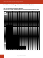
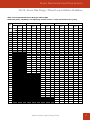
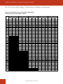
Table 2-1: Copper Type “L” Piping Specifications
Pipe size*
Flow rate**
3/4” [19.1 mm]
2 [7.6]
4 [15.1]
6 [22.7]
8 [30.3]
10 [37.9]
Pressure
Drop***
1.5 [0.5]
5.0 [1.5]
10.0 [3.0]
17.0 [5.1]
25.0 [7.5]
Volume****
2.7 [10.1]
Pipe size*
Flow rate**
1” [25.4 mm]
10 [37.9]
12 [45.4]
14 [53.0]
16 [60.6]
Pressure
Drop***
7.0 [2.1]
9.0 [2.7]
13.0 [3.9]
16.0 [4.8]
Volume****
4.1 [15.3]
*Nominal inside diameter water pipe -- e.g. 3/4” type L has an inside diameter of 0.811” [206 mm] & an outside diameter of 0.875” [222 mm]
**U.S. gallons per minute [liters per minute]
***Foot of head per 100 ft. of pipe [meters of head per 30m of pipe]
****U.S. gallons per 100 ft. of pipe [liters per 30m of pipe]
PIPING SYSTEM INSTALLATION
Once the piping system has been designed, proper installation
techniques must be used to insure a problem-free system. When
piping is hung, 1-1/4” [32 mm] and smaller tubing must be
supported every 6 ft. [1.8 m]; 1-1/2” [38 mm] and larger tubing
must be supported every 10 ft. [3 m]. Always support the pipe
where a transition from horizontal to vertical is made. Plastic
coated or copper hangers should be used, allowing enough space
for the pipe insulation. Standoff type supports are good for rigid
support, wall runs or short runs less than 10 ft. [3 m]. Clevis
hangers (held by threaded rod) are good for piping at different
heights. Finally, rail type hangers are good for different types of
pipe (e.g. water, conduit, etc.). Polyethylene clips are best for small
pipes. Always run piping at 90 or 45 degree angles. Local codes
supersede any recommendations in this manual.
Two types of soldering material may be used for hydronic
installations, 50/50 [50% tin, 50% lead] and 95/5 (95% tin, 5%
antimony). However, 50/50 may not be used for domestic water
piping. Solder type 50/50 1/8” [3.2 mm] diameter solder has a
22
Once the fitting has been prepared, take care not to use too much
solder. Look for a silver ring to appear on the fitting. When solder
drips, the joint has excess solder. Excess solder can get into the
system circulating fluid. Note that approximately 0.9” [23 mm]
of 1/8” [3.2 mm] diameter solder is all that is needed for 3/4” [19
mm] copper; 1.3” [33 mm] is needed for 1” [25 mm] copper; and
1.7” [43 mm] is needed for 1-1/4” [32 mm] copper.
Let the joint cool naturally. Cooling with water can cause high
stress at the joint area, and potentially premature failure (this is
especially important when heavy objects are soldered in place,
such as pumps). Once the joint is cool, wipe any excess flux
to lessen potential surface oxidation. Keep the piping open to
the atmosphere. Pressure can cause blowout of material when
heated, causing pin hole leaks. When a thread by sweat (soldered)
transition fitting is used, always make the soldered connection
first, and then make the threaded fitting [with proper sealants].
Adequate ventilation must be present when soldering. Flux fumes
can be dangerous.
Bryant: Whatever It Takes.
Bryant Geothermal Heat Pump Systems
Part II: Load Side Design Components
When soldering valves and unions, take care not to overheat the
non-metallic components. Remove synthetic gasket material from
dielectric unions before soldering. Likewise, use small strips of
damp, clean rags to keep the valve body when soldering.
Safety
Bryant is always concerned about the safety of installation
technicians. Exercise caution when soldering around combustible
materials, wood, plastic or paper. Cleaning fluids, pressurized
containers and other hazardous materials should be removed
before beginning any solder joints.
Always wear eye protection, long sleeve shirts and gloves when
installing Bryant equipment and related systems/components. Use
shields on safety glasses. Always have the proper fire extinguisher
and/or water near the work area.
Local codes supersede any recommendations in this manual.
System Components
Below are some general guidelines for component selection and
design/installation criteria for the piping system. Local codes
supersede any recommendations in this manual.
Shut off/flow regulation valves: Use full port ball valves
or gate valves for component isolation. If valves will be used
frequently, ball valves are recommended. Globe valves are designed
for flow regulation. Always install globe valves in the correct
direction (fluid should enter through the lower body chamber).
Check valves: Swing check valves must be installed in the
horizontal position with the bonnet of the valve upright. Spring
check valves can be mounted in any position. A flow check valve is
required to prevent thermo siphoning (or gravity flow) when the
circulator pump is off or when there are two circulators on the
same system.
Mixing valves: Three and four port thermostatic mixing valves
are common in hydronics applications, especially when boilers are
used. Most oil and gas-fired boilers cannot accept cool return
water without flue gas condensation problems. Three-way mixing
valves are limited to systems where the coolest return water from
the distribution system is always above the dew point temperature
of the exhaust gases. When this is not possible, a four-port mixing
valve should be used.
Buffer tanks: A buffer tank is required for all hydronic heating
systems using water-to-water heat pumps and chilled water
systems. Buffer tank sizing is address earlier in this section. The
buffer tank must be A.S.M.E. rated (approved for use as a heating
vessel). See note below regarding pressure relief valves.
Pressure relief valves: Most codes require the use of a
pressure relief valve if a closed loop heat source can be isolated
by valves. Even if local code does not require this device, Bryant
recommends its installation. If the pressure relief valve in the buffer
tank is rated above 30 psi [207 kPa] maximum pressure, remove
the existing valve and replace with the lower rated model. The
pressure relief valve should be tested at start up for operation.
This valve can also be used during initial filling of the system to
purge air. Note that the waste pipe must be at least the same
diameter as the valve outlet (never reduce), and that valves may
not be added to this pipe. The bottom of the pipe must be at
least 6” [15 cm] from the floor. If the piping is connected to a
drain, there must be an air gap.
Backflow prevention check valves: Most codes
require backflow prevention check/fill valves on the supply water
line. Note that a single check valve is not equal to a backflow
prevention check valve. Even if local code does not require this
device, Bryant recommends its installation. This is particularly
important if the system will use antifreeze.
Pressure-reducing valves or feed water valves: This
valve lowers the pressure from the make-up water line to the
system. Most are adjustable and directional. A “fast fill” valve is a
must for initially filling the system. Some have screens, which must
be cleaned after the initial filling. If there is a restriction in the
screen, the system could go to zero pressure, potentially causing
pump(s) failure or pressure relief valves to open. A valve on each
side of the pressure-reducing valve should be installed for servicing.
Both valves should have tags reading, “Do not shut this valve under
normal operation – Service valve only”.
Expansion tanks: Expansion tanks are required on hydronics
systems to help absorb the pressure swings as the temperature
in the system fluctuates. If the piping system will be used for
chilled water, the tank must be insulated. A non-metallic (plastic,
fiberglass) tank is recommended for chilled water systems to
lengthen the life expectancy of the expansion tank.
Elbows/T’s: Calculate added pressure drop of elbows and T’s in
the system when considering pump sizing and pipe diameter selection.
Anti-freeze: Antifreeze is required if any of the piping system
is located in areas subject to freezing. In addition, antifreeze should
be used for snow melt systems and fan coil unit installations where
design water temperatures drop below 40°F [4°C]. Consult the
antifreeze manufacturer’s specifications catalog for concentration
amounts and recommendations.
Well-type thermistors & aqua-stats: All thermistors
and aqua-stats should be installed in a thermal well for more
accurate sensing of the water in the tank. The well should be
threaded into an opening in the tank, and the thermistor or aquastat probe should be coated with conductive paste to make sure
that the sensor is in contact with the walls of the well. Figure 2-6
shows a typical well-type installation. Attaching a thermistor or
aqua-stat to piping outside of the tank only senses temperature
accurately when the pumps are running, and may create false
readings, which could short cycle the heat pump or cause
overheating of the tank.
Water-to-Water System Design Guide
23
Water-to-Water System Design Guide
Part II: Load Side Design / Distribution Design
Figure 2-6: Well-Type Thermistors & Aqua-Stats
Spud
Insertion
Well threads into tank
Thermistor bulb inserts
into well, filled with
conductive paste for
good thermal contact
HYDRONIC HEATING / COOLING
DISTRIBUTION DESIGN
SOURCE & LOAD PUMP SIZING
50YEW series units are available with optional internal source and
load pumps. See Part III for pump curves. The ground loop and
load piping (heating system) must be designed to provide proper
water flow through the unit heat exchangers using the internal
pumps. For all other units, review the Bryant Flow Controller I.O.M.
manual for source side (loop) pump sizing. This section provides
a guideline for load pump sizing with maximum piping lengths and
typical valving configurations. Consult the ASHRAE Fundamentals
Handbook for pressure drop calculations not meeting the guidelines
in this section.
For units up through the 50YEW010 / GSW060, one 1/6 hp (245
W power consumption) circulator pump (Grundfos UP26-99 or
equivalent) will be sufficient for the load side piping, providing the
following guidelines are not exceeded:
• Maximum one-way distance from the water-to-water unit to
the buffer tank of 25 ft. [7.6 meters]
• Minimum copper tubing size for units up through the GSW036
of 3/4” [19 mm] I.D.; minimum size for units up through the
50YEW010 / GSW060 of 1” [25 mm] I.D.
• Maximum of 8 elbows.
• Maximum components limited to those shown in Drawings 2-1
through 2-9.
• Only one water-to-water unit is piped to each buffer tank.
IMPORTANT DESIGN NOTE: Depending upon the
temperature difference between the entering and leaving load
temperatures, the buffer tank and/or domestic hot water tank may
require lower settings. For example, if the load pump selection for
a 50YEW010 provides a temperature difference of 5°F [3°C] when
the total pressure drop of the system is considered [piping, valves,
heat exchanger pressure drop, etc.], the tank could be set as high as
140°F [60°C], since the maximum leaving water temperature for the
50YEW series is 145°F [63°C]. However, if the design temperature
difference is 10°F [6°C], the tank temperature must be lowered to
a maximum of 135°F [57°C] to avoid a leaving water temperature
above the maximum allowed, potentially causing nuisance lockouts. It
is always a good idea to provide a few degrees “buffer” for operating
conditions where the temperature difference could be lower.
24
NOTICE:
Well should be located in the bottom half of the tank.
If well is near the top of the tank, thermistor/aqua-stat
will react too slowly, and a demand for heating may not
be made until the tank is drawn down to the thermistor
level (especially important with DHW heating).
This section looks at the design parameters associated with each
of the delivery systems, particularly when retrofitting an existing
hydronic heating system. Domestic water heating, baseboard
radiation, cast iron radiators, radiant floor heating and fan coil units
will be addressed in this section.
Domestic Water Heating
A water-to-water heat pump is a very efficient means for generating
domestic hot water (DHW). Typically, a water-to-water unit is 4 to
6 times more efficient than an electric water heater, providing much
lower annual operating costs. Recovery rate is much better than
an electric water heater and similar to fossil fuel water heaters. For
example, a typical electric water heater has a capacity of 4.5 or 5.5
kW. Bryant’s smallest water-to-water unit is 8 kW. Most fossil fuel
water heaters have output capacities of 28,000 Btuh to 32,000 Btuh
[8.2 to 9.4 kW], depending upon efficiency.
Bryant’s 50YEW series heat pumps are already designed for water
heating. A 3-way valve is optional, which allows the unit to switch
between space heating and domestic water heating. Leaving
water temperatures up to 145°F [63°C] are possible with the
50YEW series. An indirect-fired water heater or a secondary
heat exchanger and pump is required to keep the heating water
loop separate from the potable water. Bryant 50PSW and
GSW series water-to-water heat pumps also have the capability
to heat domestic hot water, but the maximum leaving water
temperatures are in the 130°F [54°C] range, and the units do not
have the controls in place for switching between space heating and
domestic water heating.
CAUTION:
Maximum leaving water temperature of the 50YEW series
equipment is 145°F [63°C]. For domestic hot water tank
temperatures or heating buffer tank temperatures above
130°F [54°C], pump and pipe sizing is critical to insure that
the flow rate through the heat pump is sufficient to maintain
leaving water temperatures below the maximum temperature,
and to provide water flow rates within the ranges shown in
the performance section of this manual.
Bryant: Whatever It Takes.
Bryant Geothermal Heat Pump Systems
Part II: Load Side Design / Distribution Design
When generating DHW with a heat pump or boiler, potable water
must never come in contact with heating water. Therefore, an
indirect water heater or secondary heat exchanger is required. As
shown in figure 2-7, an indirect water heater has a coil inside the
tank to isolate the two liquids (potable water and heating water).
Figure 2-8 shows a brazed plate heat exchanger that can be used
in between the heat pump and direct water heater (electric, oil,
natural gas, propane). Only one pump is needed for an indirect
water heater (the water-to-water unit’s load pump circulates water
between the heat pump heat exchanger and the water heater
heat exchanger), but two pumps are required when a secondary
or brazed plate heat exchanger is used (one pump between the
water-to-water unit and the brazed plate and one pump between
the brazed plate and the water heater).
Figure 2-7: Indirect Water Heater
Potable Water
H
Indirect
(water-to-water)
Heat Exchanger
C
Some indirect water heaters have electric elements for use as
backup. The 50YEW series equipment has an emergency DHW
function that will send a 24VAC signal to a field-installed contactor
to energize the backup electric elements if the unit is locked out.
A direct electric water heater could also be used for backup when
a brazed plate heat exchanger is installed.
IMPORTANT DESIGN NOTE: Most indirect water
heaters are designed for 180°F [82°C] water circulating through
the heat exchanger. At lower water temperatures capacities are
significantly reduced. Make sure that the heat exchange capacity is
adequate at the lower water temperatures used by water-to-water
heat pumps. Some indirect solar water heater manufacturers
publish data at lower water temperatures, and some European
manufacturers of indirect water heaters have significantly more
heat exchange surface (i.e. more coils), which will allow the use
of cooler water. Brazed plate heat exchanger sizing is also critical
for the same reason. Larger heat exchangers will be required for
lower DHW temperatures.
Figure 2-9: Indirect Water Heaters
Load Connections
to Boiler/Heat Pump
LOAD
IN
OUT
TOP VIEW
OUT
IN
SOURCE
Figure 2-8: Brazed Plate Heat Exchanger
“Typical” indirect water
heater rated for 180°F
(82°C) or hotter water.
Indirect water heater with more surface
area (photo courtesy of TURBOMAX).
Consult manufacturer’s data for operating
at lower water temperatures.
SIDE VIEW
Water-to-Water System Design Guide
25
Water-to-Water System Design Guide
Part II: Load Side Design / Distribution Design
RADIANT FLOOR HEATING
Radiant floor heating has been used for centuries. The Romans
channeled hot air under the floors of their villas. In the 1930s,
architect Frank Lloyd Wright piped hot water through the floors
of many of his buildings. Home builders’ surveys have shown that,
if given a choice, most new home owners prefer radiant floor heat
over other types of systems. A simple 1” [25mm] diameter pipe
can carry as much heat as a 10” x 19” [254 x 483 mm] rectangular
duct carrying hot air at 130°F [54°C].
Comfort is improved with radiant floor systems. A room with
radiant floor heating will have an average floor temperature of
80-85°F [27-29°C] with an overall room temperature at occupant
level of 68-70°F [20-21°C]. In forced air systems temperatures
near the ceiling often reach 90-100°F [32-38°C], which can be
20-30°F [11-17°C] higher than the temperature at the floor. (see
figures 2-10a and 2-10b). Therefore, radiant floor heating is more
comfortable because heat is directed to occupant level. Radiant
floor heating systems may also lower operating costs, since a
lower thermostat setting is typically used for this type of system as
compared to forced air. The lower heat loss at the ceiling lowers
the temperature difference between the ceiling and the outside,
resulting in a smaller heat loss, which lowers the heat pump
capacity required to heat the structure.
95º
10º
60º
90º
60º
60º
79º
85º
95º
74º
65º
65º
65º
59º
81º
81º
81º
68º
100º
63º
Forced Air System
Radiant Floor Heat
Figure 2-10b: Celsius
-12º
35º
-12º
16º
32º
29º
35º
16º
23º
18º
18º
18º
15º
27º
27º
27º
20º
38º
17º
Forced Air System
26
16º
26º
Radiant Floor Heat
Advantages of Geothermal Radiant Floor Heating:
• Independent zoning
• Ductless
• Quiet
• Reliable, fewer moving parts
• Easily controlled
• Space savings - Fewer limitations of furniture or
room arrangements
• Can be matched to another system for air conditioning,
if needed
• Equipment requires smaller installation footprint than a standard
boiler installation.
• Does not require complex ventilation to vent away potentially
harmful combustion gases
• No combustion chamber to maintain and clean
• No risk of carbon monoxide (CO) poisoning
• Simple controls - One thermostat or zoned thermostats
Most people who own radiant floor heating systems feel that
the most important advantages are comfort and quiet operation.
Radiant floor systems allow even heating throughout the whole
floor, not just in localized spots as with other types of heating
systems. The room heats from the bottom up, warming the feet
and body first.
Figure 2-10a: Fahrenheit
10º
Conventional cast iron radiators or fin-tube baseboard units often
present obstacles to the effective use of floor and wall space
within a room. They severely restrict the placement of furniture, as
well as the placement of paintings, wall hangings, and other decor.
With radiant floor technology, these obstacles are eliminated giving
homeowners more freedom to arrange their rooms as they choose.
Radiant floor heating also allows for lower water temperatures,
which uses less energy and lowers utility bills. Radiant floors
operate between 85-140°F [29-60°C], compared to other
hydronic heating systems’ range of 130-180°F [54-82°C].
To some, the greatest advantage of radiant floor heating is
aesthetic. The system is “invisible.” There are no heat registers or
radiators to obstruct furniture arrangements and interior design
plans. Radiant floor systems also eliminate the fan noise of forced
hot air systems.
Combining the advantages of radiant floor heating with the
advantages of geothermal technology provides unmatched
comfort and savings. Plus, Bryant water-to-water units can share
the same ground loop with the water-to-air cooling system, or can
be used for chilled water for fan coil units. Most systems, however,
use a separate forced air geothermal system for the ultimate in
comfort, energy cost savings and ease of control. Radiant floor
heating and geothermal systems provide home owners with stateof-the art heating and cooling.
Homes are not the only benefactors of radiant floor heating
systems. Industrial buildings, especially those with high ceilings
and large overhead doors, have an advantage with a radiant
floor heating system. Heat energy is stored in the concrete floor.
Bryant: Whatever It Takes.
Bryant Geothermal Heat Pump Systems
Part II: Load Side Design / Distribution Design
When a door is opened, the stored heat is released to the space
immediately. The larger the temperature difference between the
air in the space and the floor, the quicker the floor releases its heat
to the space.
Maintenance garages benefit from radiant floor heating systems.
Cold vehicles brought into the garage are warmed from
underneath. The snow melts off the vehicle and dries much more
quickly than when heated from above. In addition, mechanics who
work on the vehicles will be more productive, especially when
their work requires them to lie on the floor.
• Piping layout – always consult the piping manufacturer’s
literature for the best layout.
The spacing of the pipe in residential applications can vary from 4”
to 12” [10 to 30 cm]. If the spacing is too great, the temperature
of the floor can vary noticeably. The design of the radiant
floor piping system is beyond the scope of this manual. Most
distributors of radiant floor piping and accessories offer some
design assistance to heating and cooling contractors.
Health care centers and child care centers can benefit greatly
from radiant heating. Since children play on the floor frequently,
the benefits of a warm floor will keep children from getting chilled
while playing.
Once the load calculations have been finished, the water-to-water
equipment [and loop if applicable] has been sized, and the buffer
tank has been designed, the radiant floor piping system can be
designed based upon the water temperature in the buffer tank
(i.e. aqua-stat set point or maximum water temperature at design
conditions if using outdoor reset).
Figure 2-11: Radiant Floor Zone Manifold
BASEBOARD RADIATION
In existing systems, baseboard radiation is typically designed to
operate with 160-200°F [71-93°C] water or steam. Baseboard
radiators are usually constructed of copper tube with closely
spaced aluminum fins attached to provide more surface area
to dissipate heat, as shown in figure 2-12. Some of the factors
affecting the amount of heat given off by fin tube radiators are the
water temperature, water flow, air temperature, pipe size and fin
size/spacing. A decorative cover is normally fitted over the fin tube.
Some of the factors affecting the heating capacity
of a floor heating system are:
• Spacing of the pipe – tighter spacing increases heating capacity.
• Water flow through the pipe – more water flow increases
capacity (high flow rates, however, increase pressure drop and
may result in larger pumps).
• Temperature of the supply water – higher temperature
increases heating capacity of the floor.
• Sub-floor material (wood, concrete or light-weight poured
concrete) – concrete is best.
• Floor covering (ceramic tile, carpet, wood, etc.) – be careful
with carpeting, which is an insulator, and may require hotter
water and/or tighter pipe spacing depending upon pad type,
carpet type, and thickness.
• Insulation value under the floor – make sure that the system is not
heating the ground underneath instead of the conditioned space.
Another alternative for baseboard radiation is double-stack convection,
where there are two rows of fin/tubes within the enclosure. This
denser design allows for the use of cooler water temperatures.
Figure 2-12: Baseboard Radiation
Aluminum Fins
Copper Tube
Enclosure
Wall
In residential applications occupants in a space feel comfortable
with lower air temperatures if their feet are warm. Typically the
space will feel comfortable with air temperatures as low as 65°F
[18°C]. Since the heat loss of a building is directly related to
the temperature difference between inside and outside, a lower
temperature difference also means the heat loss is lower.
In some cases, water-to-water heat pumps can replace a boiler
that was used to generate hot water for baseboard radiation. For
example, if an existing home has had weatherization and insulation
upgrades, it is possible that the heat loss of the home has decreased
enough to allow lower water temperatures. Manufacturer’s data
on the baseboard convector should be consulted to determine
the Btuh/ft. of radiation [W/m] at lower water temperatures. The
50YEW series can provide up to 145°F [63°C] for baseboard
radiation. Higher water temperatures, however, lower the C.O.P. of
the heat pump, so lower water temperatures are better if possible.
Copper Tube
Aluminum Fins
Floor
Water-to-Water System Design Guide
27
Water-to-Water System Design Guide
Part II: Load Side Design / Distribution Design
The heating capacity of a baseboard system is a factor of the area
of copper tube and fins exposed to the air, and the temperature
difference between the air and the fin tube. The velocity and
volume of water flowing through the baseboard affects the
temperature of the copper and fins. Baseboard units are normally
rated in heat output per length of baseboard at a standard water
temperature and flow rate. Manufacturers provide charts, which
will give the capacities at temperatures and flow rates below the
standard. Table 2-2 shows approximate heating capacities for fin
tube radiation using water from 100-200°F [43-93°C].
The operation of a baseboard radiation system depends on the
ability to set up convection current in the room (i.e. air is warmed
by the fin tube, rises and is displaced by cool air). It is important
to ensure that the heat output of the system is adequate to meet
the heat loss of the room or building at the temperatures the
geothermal system is capable of producing. Baseboard radiation
is limited to space heating. Cooling is typically provided by a
separate, forced air distribution system.
Table 2-2: Heating Capacity in Btuh/Foot [Watts/
meter] of Baseboard Radiators
Average Water
Temperature
110°F [43°C]
120°F [49°C]
130°F [54°C]
140°F [60°C]
200°F [93°C]
55°F [13°C]*
190-380 [184-364]
240-480 [230-463]
295-590 [282-568]
350-700 [338-673]
Entering Air Temperature
65°F [18°C]*
160-320 [154-308]
205-410 [197-394]
265-532 [255-512]
315-630 [302-607]
700-1400 [673-1345]
70°F [21°C]*
150-300 [144-289]
195-390 [187-374]
245-490 [236-472]
295-590 [282-568]
*Table values are in Btuh/ft. [W/m]
The heating capacity in Btuh/foot [Watts/meter] of baseboard
radiators drops as the water temperature is reduced. The heating
capacity of most copper fin tube baseboard radiators is rated
using 200°F [93°C] water and 65°F [18°C] air temperature. Listed
above is the range of heating capacities of baseboard radiators
at the standard temperatures and the capacities when the
temperatures are reduced to the operating range of a heat pump
system. Some of the factors that affect the capacity of a radiator
are as follows:
• Size of the fins - range from 2.75” x 3” [7 x 7.6 cm] to 4” x
4”[10.2 x 10.2 cm]
• Fin spacing - 24 to 48 per foot [79 to 157 per meter]
• Size of copper tube - range from 3/4”[19 mm] to 2” [50 mm]
• Fin material - aluminum or steel
• Configuration and height of the enclosure
• Height unit is mounted from the floor
• Water flow through the tubing
Generally, the smaller fins with less fins per foot [meter] will have
lower heating capacity. Larger copper tube diameter and/or more
aluminum fins will have higher capacity. Higher water flow will
increase capacity. Adding a second fin tube to the same enclosure
will increase the capacity by 50 to 60%. Adding two fin tubes with
enclosures will increase the capacity by 75 to 80%. Baseboards are
available, using two or three fin tubes tiered above one another
in the same cabinet. The air can be heated enough with the
additional surface area to set up a convection current with water
temperatures as low as 110-130°F [43-54°C].
28
CAST IRON RADIATION
Retrofit applications for hydronic / geothermal heat pump systems
are often required to work with existing cast iron radiators.
Typically, cast iron radiator systems, as shown in figure 2-13, operate
with water temperatures of 125-200°F [52-93°C]. As with
baseboard systems, if an existing home has had weatherization and
insulation upgrades, it is possible that the heat loss of the home
has decreased enough to allow lower water temperatures. Cast
iron radiators can operate well with design water temperature
as low as 110°F [43°C]. Careful consideration must be made,
however, when operating at lower temperatures, as the heat
emission rate is substantially less when operating below 140°F
[60°C]. To determine heat emission for cast iron radiators, calculate
the surface area of the radiator, and refer to table 2-3 for output
capacity. Note: Table 2-3 is for general reference only. The various
cast iron radiator styles and sizes will change the output. Many
resources are available for determining heating capacities. Also
consult the radiator manufacturer’s data when possible.
Figure 2-13: Cast Iron Radiator
W
H
Bryant: Whatever It Takes.
Bryant Geothermal Heat Pump Systems
Part II: Load Side Design / Distribution Design
Table 2-3: Typical Cast Iron Radiator Capacities
Design Water
Temperature,
°F [°C]
110 [43]
120 [49]
130 [54]
140 [60]
180 [82]
200 [93]
Btuh per
sq ft
Watts per
sq m
30
50
70
90
170
210
95
158
221
284
536
663
FAN COIL UNITS
Fan coil units (or air handlers) consist of a hot water coil and/or
chilled water coil (usually copper tubing with aluminum fins) and
a fan or blower to move the air over the coil. The term “fan coil
unit” typically applies to smaller units, which are installed in the
zone or area where the heating or cooling is needed. The term
“air handler” normally refers to larger units. Fan coils are available
in many different configurations, sizes and capacities from a number
of manufacturers. Some are designed to be connected to a
ductwork system and can be used to replace a forced air furnace.
Others are designed for use without ductwork, and are mounted
in a suspended ceiling space with only a grill showing in place of
a ceiling tile. There are also console type fan coils that can be
mounted on a wall under a window or flush with the wall surface.
A typical horizontal fan coil illustration is shown in figure 2-14.
Figure 2-14: Typical Horizontal Fan Coil
Fan coils and air handlers typically have one or two coils and
a blower. Air is heated by hot water circulated through a hot
water coil. Chilled water is circulated through the coil if cooling
is needed. Depending upon the application, the unit will include
one coil for both heating and cooling (hot water/chilled water) or
a coil dedicated to heating (hot water) and another coil specifically
for cooling (chilled water). Blowers can be provided to fit various
applications, with or without ductwork. Unit heaters (small, wallmounted fan coils) typically use axial fans in applications where
ductwork is not needed.
Fan coil units have been used to heat buildings using water
temperatures as low as 90-100°F [32-38°C]. As with radiators/
baseboard convectors, heating capacities fall dramatically when
operated below design temperatures. Table 2-4 shows the heating
correction factors for lower water temperatures. For example, a
fan coil designed for 180°F [82°C] entering water temperature and
70°F [21°C] entering air temperature would have only 36% of its
original heating capacity when operated at 110°F [43°C] entering
water temperature. For this reason, two coils are recommended if
the fan coil will be used for forced air space heating, one for heating,
one for cooling. Careful consideration should be given to fan coil
selection, since the heating and cooling coils could be significantly
different in physical size. Proper fan coil selection may involve
selecting a larger model with multiple fan speeds in order to satisfy
the capacity requirements without providing too much airflow.
Manufacturers’ literature will be necessary for proper selection.
In a retrofit situation when replacing a conventional boiler, care
must be taken to ensure that any air handlers or fan coil units in
the building will heat the building with cooler water temperatures,
and will be able to handle the increased flow rates if necessary. If
the insulation levels of the building are being upgraded, the existing
coils may meet the lower heat loss of an upgraded building with
lower water temperatures.
Table 2-4: Fan Coil Heating Water Temperature
Capacity Correction Factor Table
EAT
°F [°C]
65 [18]
68 [20]
70 [21]
100 [38]
0.318
0.295
0.272
110 [43]
0.409
0.386
0.363
120 [49]
0.500
0.478
0.455
EWT °F [°C]
130 [54] 140 [60]
0.591
0.682
0.568
0.659
0.545
0.636
145 [63]
0.728
0.705
0.682
150 [66]
0.773
0.750
0.727
Water-to-Water System Design Guide
180 [82]
1.045
1.023
1.000
29
Water-to-Water System Design Guide
Part II: Load Side Design /
Distribution Design
SNOW MELTING APPLICATIONS
Although snow melting is now considered somewhat controversial
due to the energy use, geothermal systems are quite capable of
heating sidewalks and driveways for melting snow. As with any
hydronic heating system, the load calculation is the first and most
important step in designing a reliable and cost-effective snow melt
system. Consult the ASHRAE HVAC Applications Handbook
for slab piping design and temperature requirements. This will
determine the Btu/hr [kW] requirement of the water-to-water
equipment. Follow procedures above for sizing the equipment and
buffer tank.
The hot water in the piping system will heat the slab, melting the
snow. Snow melt controls are available that actually “sense” when
conditions are right for snowfall. Snow/ice melt detection is used
to automatically start and stop a snow melt system. When there
is snow on the sensor, the sensor melts the snow/ice, detects the
moisture and allows the control to start the melting process. This
prevents accumulation of snow on the slab and provides a faster
response. Automatic snow/ice detection is safer, more convenient
and consumes less energy than manual (ON/OFF) type systems.
In systems where snow and ice removal is critical, such as hospital
ramps, the pick up time for a snow melting slab can be reduced
by maintaining the slab at an idling temperature. The idling
temperature may be just below the freezing point. When snow
melting is required, the slab temperature is increased. When
the slab and outdoor temperatures are warm enough, the snow
melting system should automatically turn off.
Cooling and dehumidifying fresh air used for ventilation as it is
brought into the building (using a dedicated outside air system) can
sometimes provide the additional cooling needed. Care must be
taken to avoid cooling the radiant surface below the dew point.
A water-to-water heat pump system can provide chilled water to
ducted or non-ducted fan coil units. A reversible water-to-water
heat pump can provide chilled water to cool the building, as well
as hot water for the heating system. Buildings with fan coil units
can generally be retrofitted for cooling quite easily. The difficulty, as
mentioned above, is using existing fan coils for heating, especially if
they were originally sized for higher water temperatures.
For optimal cooling and dehumidification, Bryant recommends a
separate water-to-air heat pump for cooling. Controls are much
simpler when a water-to-water unit is used for space heating
and/or domestic water heating, and a water-to-air unit is used for
cooling. Since the water-to-water and water-to-air units can share
one ground loop, the installation cost of using a water-to-air unit
for cooling is simply the incremental cost of the unit. Generally, no
additional ground loop is required, and the cost of the water-toair unit is usually less than the cost of chilled water/fan coil units,
especially if the cost of additional piping/valving/controls and labor
is considered. The cost of a water-to-air unit is approximately
the same as a ductless mini split, and is much more efficient. The
advantages of geothermal heat pumps for cooling (no outdoor
unit, no refrigerant line sets, longevity, etc.) should be considered
when cooling is required.
Another important aspect of choosing a good controller is slab
protection. Snow melt systems deal with extreme temperature
differences. Limiting the rate of heat transfer into the slab
provides slab protection. This is done by slowly ramping up the
temperature difference across the slab and limiting the maximum
temperature difference. This function prevents cracking of the slab
due to thermal expansion caused by high heat output.
Piping design and component selection for a snow melt system
are identical to systems used for hydronic heating (see drawings
2-3 and 2-4). The difference is simply the load on the system. In
other words, the size of the water-to-water unit and the related
components is calculated based upon the amount of heat needed
for a sidewalk [for snow melting] instead of the amount of heat
needed to condition a structure.
COOLING SYSTEMS
Cooling an existing building with a radiant heating system can
be a challenge. If radiant heating emitters (radiators, baseboard
convectors, radiant floor piping) are cooled lower than the dew
point, condensation will form on the floor or drip off the emitters.
A limited amount of cooling can be accomplished by circulating
chilled water through the piping in the floor or through radiant
ceiling panels. This can be effective in buildings with high solar
loads or lighting loads, where much of the heat gain is radiant heat.
30
Bryant: Whatever It Takes.
Bryant Geothermal Heat Pump Systems
Part III: Source Side Design / System Selection
SYSTEM DESIGN
System Selection
Figures 3-1a and 3-1b present system selection in flow chart format
for the source side of the water-to-water unit. There are five piping
schematics following the flow charts that illustrate each of the
possible choices. To select the correct drawing, begin in figure 3-1a,
and finish the selection process in figure 3-1b if necessary.
Figure 3-1a: System Selection Flow Chart (Part 1)
Start
(Source Side
Applications)
NOTE: Green arrows indicate Bryant
recommended applications.
Use 50PSW or GSW series
Reversible Model
Cooling
System?
Chilled Water / Fan Coil
Chilled Radiant Floor
50YEW?
No Cooling
No
Yes
See drawing 3-1 (external
pumps / no water-to-air
cooling unit )
Separate Cooling System
Internal
Source
Pump(s)?
Yes
No
No
1
Yes
Is clg
system a
water-to-air
unit?
No
See drawing 3-2 (50YEW
internal pumps / no
water-to-air cooling unit )
50YEW?
See drawing 3-1 (external
pumps / no water-to-air
cooling unit)
Yes
No
No
Internal
Source
Pump(s)?
Yes
Is clg
system a
water-to-air
unit?
Water-to-Water System Design Guide
Yes
2
31
Water-to-Water System Design Guide
Part III: Source Side Design / System Selection
Figure 3-1b: System Selection Flow Chart (Part 2)
NOTE: Green arrows indicate Bryant
recommended applications.
1
Does each
unit have
its own
pump(s)?
2
No
Are pumps
sized for both
units running
simultaneously?
Does
water-to-air
unit have its
own
pump(s)?
Yes
Yes
No
No
See drawing 3-3 (external
pumps + water-to-air / separate
pumps )
Water-to-Air unit must be
disabled when
water-to-water unit is
running for DHW
generation.*
See drawing 3-4 ( external
pumps + water-to-air / single
pump station)
*Motorized water valve must also
be installed to allow water flow
only when unit is operating.
32
Bryant: Whatever It Takes.
Separate pump(s) for
water-to-air unit required
with internal pumps for
50YEW unit.
See drawing 3-5 (50YEW
internal pumps + water-to-air )
Yes
Bryant Geothermal Heat Pump Systems
Part III: Source Side Design / System Selection
System Descriptions
Figure 3-2: Component Legend for Drawings 3-1
to 3-5
Component Legend
M
T
3-Way Valve - Manually Operated
Pressure Relief ("Pop-Off") Valve
3-Way Valve - Motorized
Check Valve
Mixing Valve
Union
Ball Valve
Pressure/Temperature (P/T) Port
Gate Valve
Circulator Pump
Pressure Reducing Valve
Heat Exchanger
Drawing 3-1 – Heating only application with external Flow
Controller: Drawing 3-1 is used for water-to-water units without
internal source pumps. The Bryant Flow Controller includes one
or two circulator pumps, plus 3-way valves for purging air from
the system. It is important to note that when headering the
ground loop outside of the mechanical room the header must be
a reducing type in order to be able to purge air from the system at
the Flow Controller 3-way valves. Reducing headers are addressed
later in this section.
Drawing 3-1: Water-to-Water Source Piping 50YEW (No Source Pumps) or 50PSW / GSW Units
- No Cooling or Separate Cooling System
To/From Ground Loop
Flow Controller
See drawings in section 2 for Load connections
Note 1
P/T port
IN
OUT
50YEW,
50PSW,
or GSW Unit
Load HX
NOTES:
1. P/T (pressure/temperature) ports are internal for
50YEW series units.
2. Source water piping must be insulated for closed loop
installations.
3. Other components (additional ball valves, unions, etc.)
may be required for ease of service. This drawing
shows only minimum requirements. Your specific
installation will dictate final component selections.
4. Local code supercedes any piping arrangements or
components shown on this drawing.
Source HX
(coaxial)
Water-to-Water System Design Guide
20Jun07
33
Water-to-Water System Design Guide
Part III: Source Side Design / System Selection
Drawing 3-2 – Heating only application with internal source
pump(s) – 50YEW only: Drawing 3-2 is used for 50YEW series
units with optional internal source pump(s). Three-way valves are
required for purging air from the system. It is important to note
that when headering the ground loop outside of the mechanical
room the header must be a reducing type in order to be able to
purge air from the system at the Flow Controller 3-way valves.
Reducing headers are addressed later in this section.
Drawing 3-2: 50YEW Source Piping (Internal
Source Pumps) - No Cooling or Separate Cooling
System
To/From Ground Loop
Note 1
See drawings in section 2 for Load connections
IN
OUT
50YEW
Unit
Load HX
Source HX
(coaxial)
NOTES:
1. Ball valve arrangement is for purging air from the
ground loop.
2. P/T (pressure/temperature) ports are internal for
50YEW series units.
3. Source water piping must be insulated for closed loop
installations.
4. Other components (additional ball valves, unions, etc.)
may be required for ease of service. This drawing
shows only minimum requirements. Your specific
installation will dictate final component selections.
5. Local code supercedes any piping arrangements or
components shown on this drawing.
14Sep07
34
Bryant: Whatever It Takes.
Bryant Geothermal Heat Pump Systems
Part III: Source Side Design / System Selection
Drawing 3-3 – Heating with water-to-water unit and cooling
with water-to-air unit application – units without internal source
pump(s) / separate Flow Controllers for each unit: Drawing 3-3
is used for water-to-water units without internal source pumps.
The Bryant Flow Controller includes one or two circulator pumps,
plus 3-way valves for purging air from the system. The use of
a separate water-to-air unit for cooling is the Bryant preferred
application when cooling is required (drawings 3-3, 3-4, and 3-5).
This application provides better and simpler control of the heating
and cooling system. Plus, pumps can be sized specifically for each
unit’s flow rate (except drawing 3-4). Check valves are required
on the loop side of the Flow Controller piping to prevent short
cycling (i.e. bypassing the ground loop). In cases where the waterto-water unit will be generating domestic hot water in the summer
when the water-to-air unit is operating, a mixing valve may be
required to ensure that the entering source water temperature
to the water-to-water unit is not warmer than the maximum
temperature shown in the performance catalog (50PSW/GSW
units only). It is important to note that when headering the
ground loop outside of the mechanical room the header must be
a reducing type in order to be able to purge air from the system at
the Flow Controller 3-way valves. Reducing headers are addressed
later in this section.
Drawing 3-3: Water-to-Water Source Piping 50YEW (No Source Pumps) or 50PSW / GSW Units
- Water-to-Air Cooling with Separate Loop Pumps
(Bryant Preferred System When Cooling
is Desired)
To/From Ground Loop
Water-to-Air
Unit
(Cooling)
Note 4
Flow Controller
Flow Controller
Notes 2,3
Water Out
Water In
See drawings in section 2 for Load connections
P/T Port
P/T Port
OUT IN
50YEW,
50PSW,
or GSW Unit
Load HX
Note 1
NOTES:
1. P/T (pressure/temperature) ports are internal for
50YEW series units.
2. Unions are not necessary if residential swivel water
connections (60 Hz only) are used.
3. Source water piping must be insulated for closed loop
installations.
4. Pump selection (1 or 2) will be determined by size of
water-to-air and water-to-water units.
5. Other components (additional ball valves, unions, etc.)
may be required for ease of service. This drawing
shows only minimum requirements. Your specific
installation will dictate final component selections.
6. Local code supercedes any piping arrangements or
components shown on this drawing.
Source HX
(coaxial)
Water-to-Water System Design Guide
04Oct07
35
Water-to-Water System Design Guide
Part III: Source Side Design / System Selection
Drawing 3-4 – Heating with water-to-water unit and cooling
with water-to-air unit application – units without internal source
pump(s) / single Flow Controller for both units: Drawing 3-4 is
used for water-to-water units without internal source pumps. The
Bryant Flow Controller includes one or two circulator pumps,
plus 3-way valves for purging air from the system. The use of
a separate water-to-air unit for cooling is the Bryant preferred
application when cooling is required (drawings 3-3, 3-4, and 3-5).
This application provides better and simpler control of the heating
and cooling system. Plus, pumps can be sized specifically for each
unit’s flow rate (except drawing 3-4). When using only one set
of source pumps, as shown in drawing 3-4, care must be taken to
ensure that all combinations of unit operation are considered. In
other words, if both units are running (e.g. water-to-water unit is
making domestic hot water and the water-to-air unit is cooling),
the pumps must be sized so that both units have sufficient water
flow. If it is not possible for both units to run with this type of
arrangement (i.e. there is not enough flow), the water-to-air unit
compressor should be locked out when the water-to-water unit is
running via a field-installed relay (water flow must also be stopped
through the water-to-air unit via a water solenoid valve). Since the
domestic hot water tank should be quickly satisfied, a momentary
disruption of cooling will be less noticeable than an interruption in
domestic hot water generation (domestic hot water priority). In
cases where the water-to-water unit will be generating domestic
hot water in the summer when the water-to-air unit is operating,
a mixing valve may be required to ensure that the entering source
water temperature to the water-to-water unit is not warmer than
the maximum temperature shown in the performance catalog
(50PSW/GSW units only). It is important to note that when
headering the ground loop outside of the mechanical room the
header must be a reducing type in order to be able to purge air
from the system at the Flow Controller 3-way valves. Reducing
headers are addressed later in this section.
Drawing 3-4: Water-to-Water Source Piping 50YEW (No Source Pumps) or 50PSW / GSW Units
- Water-to-Air Cooling (Shared Pumping with
Water-to-Water)
To/From Ground Loop
Note 2
Note 4,5
Water-to-Air
Unit
(Cooling)
Flow Controller
Notes 2,3
Water Out
Water In
P/T Port
See drawings in section 2 for Load connections
Note 2
P/T Port
Note 1
OUT IN
50YEW,
50PSW,
or GSW Unit
Load HX
36
Source HX
(coaxial)
Bryant: Whatever It Takes.
NOTES:
1. P/T (pressure/temperature) ports are internal for
50YEW series units.
2. Source water piping must be insulated for closed loop
installations.
3. Unions are not necessary if residential swivel water
connections (60Hz units only) are used.
4. Pump selection (1 or 2) will be determined by size of
water-to-air and water-to-water units.
5. Pressure drop calculation should be made to determine if flow
rate is sufficient when both units are operating (e.g. forced air
cooling (water-to-air unit) and domestic hot water generation
(water-to-water unit). If flow is not sufficient, use two Flow
Controllers (see drawing 3-9) or lock out cooling unit when
water-to-water unit is operating to generate DHW.
6. Other components (additional ball valves, unions, etc.)
may be required for ease of service. This drawing
shows only minimum requirements. Your specific
installation will dictate final component selections.
7. Local code supercedes any piping arrangements or
components shown on this drawing.
04Oct07
Bryant Geothermal Heat Pump Systems
Part III: Source Side Design / System Selection
Drawing 3-5 – Heating with water-to-water unit and cooling
with water-to-air unit application – water-to-water units with
optional internal source pump(s) / separate pump(s) for each
unit: Drawing 3-5 is used for water-to-water units with optional
internal source pumps. A combination of ball valves as shown in
the drawing is required for purging air from the system. The use
of a separate water-to-air unit for cooling is the Bryant preferred
application when cooling is required (drawings 3-3, 3-4, and 3-5).
This application provides better and simpler control of the heating
and cooling system. Plus, pumps can be sized specifically for each
unit’s flow rate (except drawing 3-4). Check valves are required at
each unit to prevent short cycling (i.e. bypassing the ground loop).
In cases where the water-to-water unit will be generating domestic
hot water in the summer when the water-to-air unit is operating,
a mixing valve may be required to ensure that the entering source
water temperature to the water-to-water unit is not warmer than
the maximum temperature shown in the performance catalog
(50PSW/GSW units only). It is important to note that when
headering the ground loop outside of the mechanical room the
header must be a reducing type in order to be able to purge air
from the system at the Flow Controller 3-way valves. Reducing
headers are addressed later in this section.
Drawing 3-5: 50YEW Source Piping (Internal Source
Pumps) - Separate Water-to-Air Cooling System
Water-to-Air
Unit
(Cooling)
To/From Ground Loop
Notes 4,5
Water Out
Water In
Note 2
Note 1
P/T Port
See drawings in section 2 for Load connections
Note 4
IN
OUT
Notes 2,3
50YEW
Unit
Load HX
NOTES:
1. Ball valve arrangement is for purging air from the
ground loop.
2. Pump selection (1 or 2) will be determined by size of
water-to-air and water-to-water units.
3. P/T (pressure/temperature) ports are internal for
50YEW series units.
4. Source water piping/components must be insulated for
closed loop installations.
5. Unions are not necessary if residential swivel water
connections (60Hz units only) are used.
6. Other components (additional ball valves, unions, etc.)
may be required for ease of service. This drawing
shows only minimum requirements. Your specific
installation will dictate final component selections.
7. Local code supercedes any piping arrangements or
components shown on this drawing.
Source HX
(coaxial)
Water-to-Water System Design Guide
14Sep07
37
Water-to-Water System Design Guide
Part III: Source Side Design / Open Loop Design
HEAT SOURCE/HEAT SINK
The heat source/heat sink for geothermal systems is determined
based upon the specific application. Where water quality is
good and a sufficient quantity of water is available, an open
loop (well water) source/sink is a very cost effective solution.
Otherwise, one of the three types of closed loop applications
may be a better choice. In any case, operating costs are
very similar, since the source/sink and heat pump are sized
according to the heat loss/heat gain of the home. All residential
applications (open or closed loop) require extended range
equipment. Bryant residential series equipment is standard with
insulated water and refrigerant circuit insulation, designed for
low temperature operation.
Open Loop (Well Water)
Typical open loop piping is shown in Figure 3-3. Shut off valves
should be included for ease of servicing. Boiler drains or other
valves should be “tee’d” into the lines to allow acid flushing of
the heat exchanger. Shut off valves should be positioned to allow
flow through the coaxial heat exchanger via the boiler drains
without allowing flow into the piping system. P/T plugs should be
used so that pressure drop and temperature can be measured.
Piping materials should be limited to copper or PVC SCH80.
Note: Due to the pressure and temperature extremes, PVC SCH40 is
not recommended.
Water quantity must be plentiful and of good quality. Consult
table 3-1 for water quality guidelines. The unit can be ordered
with either a copper or cupro-nickel water heat exchanger.
Consult Table 3-1 for recommendations. Copper is recommended
for open loop ground water systems that are not high in mineral
content or corrosiveness. In conditions anticipating heavy scale
formation or in brackish water, a cupro-nickel heat exchanger is
recommended. In ground water situations where scaling could
be heavy or where biological growth such as iron bacteria will
be present, an open loop system is not recommended. Heat
exchanger coils may over time lose heat exchange capabilities
due to build up of mineral deposits. Heat exchangers must only
be serviced by a qualified technician, as acid and special pumping
equipment is required. Desuperheater (HWG) coils can likewise
become scaled and possibly plugged. In areas with extremely
hard water, the owner should be informed that the heat
exchanger may require occasional acid flushing. In some cases, the
desuperheater option should not be recommended due to hard
water conditions and additional maintenance required.
Table 3-1 should be consulted for water quality requirements.
Scaling potential should be assessed using the pH/Calcium
hardness method. If the pH <7.5 and the calcium hardness
is less than 100 ppm, scaling potential is low. If this method
yields numbers out of range of those listed, the Ryznar Stability
and Langelier Saturation indices should be calculated. Use the
appropriate scaling surface temperature for the application,
150°F [66°C] for direct use (well water/open loop) and DHW
(desuperheater); 90°F [32°F] for indirect use. A monitoring plan
should be implemented in these probable scaling situations. Other
water quality issues such as iron fouling, corrosion prevention and
erosion and clogging should be referenced in Table 3-1.
Figure 3-2: Typical Open Loop Application
Unit Power
Disconnect
Flow
Water
Control Regulator
Valve
Pressure
Tank
Water Out
Air Pad or
Extruded
polystyrene
insulation board
Shut-Off
Valve
Thermostat
Wiring
Optional
Filter
P/T Plugs
38
Bryant: Whatever It Takes.
Boiler
Drains
Water In
Bryant Geothermal Heat Pump Systems
Part III: Source Side Design / Open Loop Design
Table 3-1: Water Quality Standards
Water Quality
Parameter
HX
Material
Closed
Recirculating
Open Loop and Recirculating Well
Scaling Potential - Primary Measurement
Above the given limits, scaling is likely to occur. Scaling indexes should be calculated using the limits below.
pH/Calcium Hardness
All
Method
-
pH < 7.5 and Ca Hardness <100ppm
Index Limits for Probable Scaling Situations - (Operation outside these limits is not recommended)
Scaling indexes should be calculated at 150°F [66°C] for direct use and HWG applications,
and at 90°F [32°C] for indirect HX use. A monitoring plan should be implemented.
Ryznar
6.0 - 7.5
All
Stability Index
If >7.5 minimize steel pipe use.
-0.5 to +0.5
Langelier
All
If <-0.5 minimize steel pipe use. Based upon 150°F [66°C] HWG and
Saturation Index
Direct well, 85°F [29°C] Indirect Well HX
Iron Fouling
Iron Fe 2+ (Ferrous)
(Bacterial Iron potential)
All
Iron Fouling
All
-
<0.2 ppm (Ferrous)
If Fe2+ (ferrous)>0.2 ppm with pH 6 - 8, O2<5 ppm check for iron bacteria
-
<0.5 ppm of Oxygen
Above this level deposition will occur.
Corrosion Prevention
6 - 8.5
pH
All
Hydrogen Sulfide (H2S)
All
Ammonia ion
as hydroxide, chloride,
nitrate and sulfate
compounds
All
Monitor/treat as
needed
-
6 - 8.5
Minimize steel pipe below 7 and no open tanks with pH <8
<0.5 ppm
At H2S>0.2 ppm, avoid use of copper and copper nickel piping or HX's.
Rotten egg smell appears at 0.5 ppm level.
Copper alloy (bronze or brass) cast components are OK to <0.5 ppm.
<0.5 ppm
Maximum Allowable at maximum water temperature.
Maximum
Chloride Levels
Copper
CuproNickel
304 SS
316 SS
Titanium
50°F (10°C)
<20ppm
<150 ppm
<400 ppm
<1000 ppm
>1000 ppm
-
75°F (24°C)
NR
NR
<250 ppm
<550 ppm
>550 ppm
100°F (38°C)
NR
NR
<150 ppm
< 375 ppm
>375 ppm
Erosion and Clogging
Particulate Size and
Erosion
All
<10 ppm of particles
and a maximum
velocity of 6 fps [1.8 m/s].
Filtered for maximum
800 micron [800mm,
20 mesh] size.
<10 ppm (<1 ppm "sandfree" for reinjection) of particlesand a maximum
velocity of 6 fps [1.8 m/s]. Filtered for maximum 800 micron [800mm,
20 mesh] size.Any particulate that is not removed can potentially
clog components.
Notes:
• Closed Recirculating system is identified by a closed pressurized piping system.
• Recirculating open wells should observe the open recirculating design considerations.
• NR - Application not recommended.
Water-to-Water System Design Guide
Rev.: 11/17/06D
39
Water-to-Water System Design Guide
Part III: Source Side Design / Open Loop Design - Closed Loop Design
Open Loop (continued)
A closed, bladder-type expansion tank should be used to
minimize mineral formation due to air exposure. The expansion
tank should be sized to provide at least one minute continuous
run time of the pump using its drawdown capacity rating to
prevent pump short cycling. Discharge water from the unit is not
contaminated in any manner and can be disposed of in various
ways, depending on local building codes (e.g. recharge well, storm
sewer, drain field, adjacent stream or pond, etc.). Most local
codes forbid the use of sanitary sewer for disposal. Consult your
local building and zoning department to assure compliance in
your area.
Closed Loop Systems
Vertical (Drilled) Closed Loop
The placement of the water control valve is important for
proper operation. Figure 3-3 shows proper placement of the
valve. Always maintain water pressure in the heat exchanger
by placing the water control valve(s) on the discharge line to
prevent mineral precipitation during the off-cycle. Pilot operated
slow closing valves are recommended to reduce water hammer.
Insure that the total ‘VA’ draw of the valve can be supplied by
the unit transformer. For instance, a slow closing valve can draw
up to 35VA. This can overload smaller 40 or 50 VA transformers
depending on the other controls in the circuit. A typical pilot
operated solenoid valve draws approximately 15VA.
Flow regulation for open loop systems can be accomplished by
two methods. One method of flow regulation involves simply
adjusting the ball valve or water control valve on the discharge
line. Measure the pressure drop through the unit heat exchanger,
and determine flow rate from tables in the installation manual
of the specific unit. Since the pressure is constantly varying,
two pressure gauges may be needed. Adjust the valve until the
desired flow of 1.5 to 2 gpm per ton [1.6 to 2.2 l/m per kW]*
is achieved. A second method of flow control requires a flow
control device mounted on the outlet of the water control valve.
The device is typically a brass fitting with an orifice of rubber or
plastic material that is designed to allow a specified flow rate.
On occasion, flow control devices may produce velocity noise
that can be reduced by applying some back pressure from the
ball valve located on the discharge line. Slightly closing the valve
will spread the pressure drop over both devices, lessening the
velocity noise. NOTE: When EWT is below 50°F [10°C], 2 gpm
per ton [2.2 l/m per kW] is required.*
* This note is for water-to-air units, which are
rated for cooling capacities. 50YEW/50PSW series
residential water-to-water units are rated for
heating capacities at 32°F [0°C] entering source
temperature. Consult unit performance data for
open loop minimum flow rates.
40
Vertical or drilled closed loop systems take up the least amount
of land or yard space. Since the heat exchange takes place along
the vertical drilled (bore) hole walls, only a small diameter hole
(typically 4” [10 cm]) is required for each ton [3.5 kW] of heat
pump capacity. Minimal spacing is required between bore holes,
typically 10 feet [3 meters] for residential applications. Depending
upon drilling costs, vertical loops may be more expensive than
horizontal or pond/lake loops, but their compact layout makes a
geothermal closed loop application possible for almost any home
that has a small yard, driveway or sidewalk. Loops can even be
installed underneath the foundation. Closed loop design and
installation guidelines (later in this section) provide details on
vertical loop designs.
Bryant: Whatever It Takes.
Bryant Geothermal Heat Pump Systems
Part III: Source Side Design / Closed Loop Design
Horizontal (Trenched or Bored) Loop
Horizontal loops may be installed with a trencher, backhoe or
horizontal boring machine. Excavation costs are usually less than
comparable vertical loops, but significantly more land space is
required. For rural installations, horizontal loops can be very cost
effective. Pipe is typically buried around five feet [1.5 meters]
deep, and may be configured in a variety of layouts, depending
upon available space and the cost of pipe versus the cost of
excavation. Between one and six pipes per trench are buried
and connected to a header system. Closed loop design and
installation guidelines (later in this section) provide details on
horizontal loop designs.
Pond/Lake Loop
Pond or lake loops are one of the most cost-effective closed
loop installations because of the limited excavation required
(supply and return line trenches to the pond). Pond loops
require a minimum of about 1/2 acres [0.2 Hectares] of land and
a minimum depth of 8 to 10 feet [2.5 to 3 meters]. Like other
closed loop installations, pond loops utilize polyethylene pipe,
but are typically laid out in a coil or “slinky” arrangement. Closed
loop design and installation guidelines (later in this section)
provide details on pond loop designs.
Water-to-Water System Design Guide
41
Water-to-Water System Design Guide
Part III: Source Side Design / Closed Loop Installation Guidelines
CLOSED LOOP DESIGN/INSTALLATION GUIDELINES
Closed Loop Basics*
Closed Loop Earth Coupled Heat Pump systems are commonly
installed in one of three configurations: horizontal, vertical and
pond loop. Each configuration provides the benefit of using the
moderate temperatures of the earth as a heat source/heat sink.
Piping configurations can be either series or parallel.
Series piping configurations typically use 1-1/4 inch, 1-1/2 inch or
2 inch pipe. Parallel piping configurations typically use 3/4 inch or
1 inch pipe for loops and 1-1/4 inch, 1-1/2 inch or 2 inch pipe for
headers and service lines. Parallel configurations require headers to
be either “closed-coupled” short headers or reverse return design.
Select the installation configuration which provides you and your
customer the most cost effective method of installation after
considering all application constraints.
Loop design takes into account two basic factors. The first is
an accurately engineered system to function properly with low
pumping requirements (low Watts) and adequate heat transfer to
handle the load of the structure. The second is to design a loop
with the lowest installed cost while still maintaining a high level of
quality. These factors have been taken into account in all of the
loop designs presented in this manual.
In general terms, all loop lengths have been sized by the
GeoDesigner loop sizing software so that every loop has
approximately the same operating costs. In other words, at the
end of the year the homeowner would have paid approximately
the same amount of money for heating, cooling, and hot water no
matter which loop type was installed. This leaves the installed cost
of the loop as the main factor for determining the system payback.
Therefore, the “best” loop is the most economical system possible
given the installation requirements.
Pipe Fusion Methods
Two basic types of pipe joining methods are available for earth
coupled applications. Polyethylene pipe can be socket fused or butt
fused. In both processes the pipe is actually melted together to
form a joint that is even stronger than the original pipe. Although
when either procedure is performed properly the joint will be
stronger than the pipe wall, socket fusion in the joining of 2” pipe
or less is preferred because of the following:
• Allowable tolerance of mating the pipe is much greater in
socket fusion. According to general fusion guidelines, a 3/4”
SDR11 butt fusion joint alignment can be off no more than
10% of the wall thickness (0.01 in. [2.54mm]). One hundredth
of an inch [2-1/2 mm] accuracy while fusing in a difficult
position can be almost impossible to attain in the field.
• The actual socket fusion joint is 3 to 4 times the cross sectional
area of its butt fusion counterpart in sizes under 2” and
therefore tends to be more forgiving of operator skill.
* All Polyethylene pipe discussed in this manual is IPS (Iron Pipe
Size) in inches.
42
• Joints are frequently required in difficult trench connections
and the smaller socket fusion iron is more mobile. Operators
will have less of a tendency to cut corners during the fusion
procedure, which may happen during the facing and alignment
procedure of butt fusion.
In general socket fusion loses these advantages in fusion joints
larger than 2” and of course socket fittings become very expensive
and time consuming in these larger sizes. Therefore, butt fusion
is generally used in sizes larger than 2”. In either joining method
proper technique is essential for long lasting joints. All pipe and
fittings in the residential price list are IGSHPA (International Ground
Source Heat Pump Association) approved. All fusion joints must be
performed by certified fusion technicians. Table 3-2 illustrates the
proper fusion times for Geothermal PE 3408 ASTM Pipe.
Table 3-2: Fusion Times for Polyethylene 3408
ASTM Pipe
Butt Fusion
Pipe Size
Socket
Fusion
Time (Sec)
Time
(sec.)
Bead,
in [mm]
3/4” IPS
8 - 10
8
1” IPS
10 - 14
Holding
Time
Curing
Time
1/16 [1.6]
60 Sec
20 min
12
1/16 [1.6]
60 Sec
20 min
60 Sec
20 min
1-1/4” IPS
12 - 15
15
1/16 - 1/8
[1.6 - 3.2]
1-1/2” IPS
15 - 18
15
1/16 - 1/8
[1.6 - 3.2]
60 Sec
20 min
2” IPS
18 - 22
18
1/8 [3.2]
60 Sec
20 min
Always use a timing device
Parallel vs Series Configurations
Initially, loops were all designed using series style flow due to the
lack of fusion fittings needed in parallel systems. This resulted in
large diameter pipe (>1-1/4”) being used to reduce pumping
requirements due to the increased pressure drop of the pipe. Since
fusion fittings have become available, parallel flow using (3/4” IPS)
for loops 2 ton [7 kW] and above has become the standard for a
number of reasons.
• Cost of Pipe - The larger diameter (>1-1/4”) pipe is twice the
cost of the smaller (3/4” IPS) pipe. However, the heat transfer
capability due to the reduced surface area of the smaller pipe
is only decreased by approximately 10-20%. In loop designs
using the smaller pipe, the pipe length is simply increased to
compensate for the small heat transfer reduction, although it
still results in around 50% savings in pipe costs over the larger
pipe in series. In some areas vertical bores using 1-1/4” pipe can
be more cost effective, where drilling costs are high.
• Pumping power - Parallel systems generally can have much
lower pressure drop and thus smaller pumps due to the
multiple flow paths of smaller pipes in parallel.
• Installation ease - The smaller pipe is easier to handle during
installation than the larger diameter pipe. The ‘memory’ of the pipe
can be especially cumbersome when installing in cold conditions.
Smaller pipe takes less time to fuse and is easier to cut, bend, etc.
Bryant: Whatever It Takes.
Bryant Geothermal Heat Pump Systems
Part III: Source Side Design / Closed Loop Installation Guidelines
In smaller loops of two tons [7 kW] or less, the reasons for using
parallel loops as listed above may be less obvious. In these cases,
series loops can have some additional advantages:
• No header - fittings tend to be more expensive and require
extra labor and skill to install.
• Simple design - no confusing piping arrangement for easier
installation by less experienced installers.
Parallel Loop Design
Loop Configuration - Determining the style of loop primarily
depends on lot (yard) size and excavation costs. For instance, a
horizontal 1 pipe loop will have significantly (400%) more trench
than a horizontal 6 pipe loop. However, the 6 pipe will have about
75% more feet of pipe. Therefore, if trenching costs are higher than
the extra pipe costs, the 6 pipe loop is the best choice. Remember
that labor is also a factor in loop costs. The 6 pipe loop could
also be chosen because of the small available space. Generally a
contractor will know after a few installations which configuration
is the most cost effective for a given area. This information can
be applied to later installations for a more overall cost effective
installation for the particular area. Depth of the loop in horizontal
systems generally does not exceed 5 feet [1.5 meters] because
of trench safety issues and the sheer amount of soil required to
move. In vertical systems economic depth due to escalating drilling
costs in rock can sometimes require what is referred to as a
parallel-series loop. That is, a circuit will loop down and up through
two or more consecutive bores (series) to total the required
circuit length. Moisture content and soil types also effect the earth
loop heat exchanger design. Damp or saturated soil types will
result in shorter loop circuits than dry soil or sand.
Loop Circuiting - Loops should be designed with a compromise
between pressure drop and turbulent flow (Reynold’s Number) in
the heat exchange pipe for heat transfer. Therefore the following
rules should be observed when designing a loop:
NOTICE: Whenever designing an earth loop heat exchanger, always
assume the worst case, soil and moisture conditions at the job site in
the final design. In other words, if part of the loop field is saturated clay,
and the remainder is damp clay, assume damp clay for design criteria.
Figure 3-4a: Typical Header Through 15 Tons
• 3 gpm per ton [3.23 l/m per kW] flow rate (2.25 gpm per ton
[2.41 l/m per kW] minimum). In larger systems 2.5 to 2.7 gpm
per ton [2.41 to 2.90 l/m per kW] is adequate in most cases.
Selecting pumps to attain exactly 3 gpm per ton [3.23 l/m per
kW] is generally not cost effective from an operating
cost standpoint. *
• One circuit per nominal equipment ton [3.5 kW] with
3/4” IPS and 1” IPS circuit per ton [3.5 kW]. This rule can be
deviated by one circuit or so for different
loop configurations.
Header Design - Headers for parallel loops should be designed
with two factors in mind, the first is pressure drop, and the second
is ability to purge all of the air from the system (“flushability”). The
header shown in Figure 3-4A is a standard header design through
15 tons [52.8 kW] for polyethylene pipe with 2” supply and return
runouts. The header shown in Figure 3-4B is a standard header
design through 5 tons [17.6 kW] for polyethylene pipe using 1-1/4”
supply and return runouts. Notice the reduction of pipe from 2”
IPS supply/return circuits 15 to 8 to 1-1/4” IPS pipe for circuits 7
to 4 to 3/4” IPS to supply circuits 3, 2, and 1. This allows minimum
pressure drop while still maintaining 2 fps [0.6 m/s] velocity
throughout the header under normal flow conditions (3 gpm/ton
[3.23 l/m per kW]), thus the header as shown is self-flushing under
normal flow conditions. This leaves the circuits themselves (3/4”
IPS) as the only section of the loop not attaining 2 fps [0.6 m/s]
flush velocity under normal flow conditions (3 gpm per ton* [3.23
l/m per kW], normally 3 gpm [11.4 l/m] per circuit). Pipe diameter
3/4” IPS requires 3.8 gpm [14.4 l/m] to attain 2 fps [0.6 m/s]
velocity. Therefore, to calculate flushing requirements for any PE
loop using the header styles shown, simply multiply the number of
circuits by the flushing flow rate of each circuit (3.8 gpm for 2 fps
velocity [14.4 l/m for 0.6 m/s]). For instance, on a 5 circuit loop, the
flush flow rate is 5 circuits x 3.8 gpm/circuit = 19 gpm [5 circuits x
14.4 l/m per circuit = 72 l/m or 1.2 l/s].
* This note is for water-to-air units, which
are rated for cooling capacities. 50YEW series
residential water-to-water units are rated for
heating capacities at 32°F [0°C] entering source
temperature. Consult unit performance data for
open loop minimum flow rates.
Closed Loop Systems
Water-to-Water System Design Guide
43
Water-to-Water System Design Guide
Part III: Source Side Design / Closed Loop Installation Guidelines
Headers that utilize large diameter pipe feeding the last circuits
should not be used. PE 1-1/4” IPS pipe requires 9.5 gpm [36 l/m]
to attain 2 fps [0.6 m/s] and since increasing the flow through
the last circuit would also require increasing the flow through the
other circuits at an equal rate as well, we can estimate the flush
flow requirements by multiplying the number of circuits by 9.5 gpm
[36 l/m] for 1-1/4” IPS. For instance, a 5 circuit loop would require
5 circuits x 9.5 gpm/circuit = 47.5 gpm [5 circuits x 36 l/m per
circuit = 180 l/m or 3.0 l/s] to attain flush flow rate. This is clearly is
a difficult flow to achieve with a pump of any size.
Header Layout - Generally header layouts are more cost effective
with short headers. This requires centrally locating the header to
all circuits and then bringing the circuits to the header. One of the
easiest implementations is to angle all trenches into a common
pit similar to a starburst. This layout can utilize the laydown or
‘L’ header and achieves reverse return flow by simply laying the
headers down in a mirror image and thus no extra piping or labor.
Figure 3-5 details a “laydown” header.
Figure 3-4b: Typical Header Through 5 Tons
Figure 3-5: Typical “Laydown” Header
44
Bryant: Whatever It Takes.
Bryant Geothermal Heat Pump Systems
Part III: Source Side Design / Closed Loop Installation Guidelines
Inside Piping - Polyethylene pipe provides an excellent no leak
piping material inside the building. Inside piping fittings and elbows
should be limited to prevent excessive pressure drop. Hose kits
employing 1” rubber hose should be limited in length to 10-15 feet
[3 to 4.5 meters] per run to reduce pressure drop problems. In
general 2 feet of head [6 kPa] pressure drop is allowed for all earth
loop fittings which would include 10-12 elbows for inside piping to
the Flow Controller. This allows a generous amount of maneuvering
to the Flow Controller with the inside piping. Closed cell insulation
(3/8” to 1/2” [9.5 to 12.7 mm] wall thickness) should be used on
all inside piping where loop temperatures below 50°F [10°C] are
anticipated. All barbed connections should be double clamped.
Flow Controller Selection - The pressure drop of the entire
ground loop should be calculated for the selection of the Flow
Controller (a pressure drop spreadsheet is downloadable from
the web site). In general, if basic loop design rules are followed,
units of 3 tons [10.6 kW] or less will require only 1 circulating
pump (UP26-99). Units from 3.5 to 6 tons [12.3 to 21.1 kW]
will require a two pump system (2 - UP26-99)*. Larger capacity
units with propylene glycol as antifreeze may require 2 - UP26116 pumps. However, the UP26-116 should be avoided where
possible, as power consumption of the 26-116 is significantly
higher than the 26-99, which will affect heating and cooling
operating costs. In many cases, where pressure drop calcuations
may call for 3 - UP26-99 pumps, try substituting 2 - UP26-116
pumps. This makes the installation much easier and reduces cost.
Chart 3-1 shows the various pump combinations. Pumps for 50Hz
units will have similar characteristics, but different model numbers.
Loop pressure drop calculation should be performed for accurate
flow estimation in any system including unit, hose kit, inside piping,
supply/return headers, circuit piping, and fittings. Use Tables 3-3A
through 3-3E for pressure drop calculations using antifreeze and
PE/rubber hose piping materials.
Prior to installation, locate and mark all existing underground
utilities, piping, etc. Install loops for new construction before
sidewalks, patios, driveways and other construction has begun.
During construction, accurately mark all ground loop piping on
the plot plan as an aid in avoiding potential future damage to the
installation (see Site Survey Sheet). This should be done before and
after loop installation. Final installation should be plotted from two
fixed points to triangulate the header/manifold location.
Loop Piping Installation
The typical closed loop ground source system is shown in Figure
3-6. All earth loop piping materials should be limited to only
polyethylene fusion in below ground (buried) sections of the loop.
Galvanized or steel fittings should not be used at any time due
to the tendency to corrode by galvanic action. All plastic to metal
threaded fittings should be avoided as well due to the potential
to leak in earth coupled applications; a flanged fitting should be
substituted. P/T plugs should be used so that flow can be measured
using the pressure drop of the unit heat exchanger in lieu of
other flow measurement means (e.g. flow meter, which adds
additional fittings and potential leaks). Earth loop temperatures
can range between 25-110°F [-4 to 43°C]. Flow rates of 2.25 to
3 gpm per ton [2.41 to 3.23 l/m per kW] of cooling capacity are
recommended for all earth loop applications. **
Figure 3-6: Typical Ground-Loop Application
* For water-to-air units. 50YEW010
water-to-water units need two pumps.
** This note is for water-to-air
units, which are rated for cooling
capacities. 50YEW series residential
water-to-water units are rated for
heating capacities at 32°F [0°C]
entering source temperature.
Consult unit performance data for
open loop minimum flow rates.
Closed Loop Systems
Flow
Controller
Unit Power
Disconnect
Insulated
Hose Kit
Thermostat
Wiring
P/T Plugs
Rev.: 06/10/05D
ASP30 Air Pad or
Extruded polystyrene
insulation board
Do not install bricks or
blocks under air pad.
Water-to-Water System Design Guide
45
Water-to-Water System Design Guide
Part III: Source Side Design / Closed Loop Installation Guidelines
Chart 3-1: Flow Controller Pump (Source) Performance & Internal (Load) Pump(s) Performance for
50YEW Units
3
Flow Rate, m /h (l/s)
35
0
(0.278)
(0.556)
(0.833)
(1.111)
(1.389)
(1.667)
(1.944)
(2.222)
1
2
3
4
5
6
7
8
[115]
30
[98]
Head, m [ft]
25
[82]
20
[66]
15
[49]
10
[33]
5
[16]
0
0
4
8
12
16
24
20
Flow Rate, US gpm
1 - UPS 26-80 (50Hz) - spd 3
2 - UPS 26-80 (50Hz) - spd 3*
3 - UP 26-99 (60Hz)*
*Pumps in series
50YEW010 (Optional) Internal Pumps
46
Source
Load
2 - UP26-99
1 - UP26-99
Bryant: Whatever It Takes.
28
32
1 - UP 26-99 (60Hz)
2 - UP 26-99 (60Hz)*
2 - UP 26-116 (60Hz)*
Bryant Geothermal Heat Pump Systems
Part III: Source Side Design / Closed Loop Installation Guidelines
Table 3-3a: Polyethylene Pressure Drop per 100ft of Pipe
Antifreeze (30°F [-1°C] EWT): 20% Methanol by volume solution - freeze protected to 15°F [-9.4°F]
3/4” IPS SDR11
1” IPS SDR11
1-1/4” IPS SCH40
1-1/2” IPS SCH40
PD (ft)
Vel
(ft/s)
Re
(ft)
Vel
(ft/s)
Re
PD (ft)
Vel
(ft/s)
Re
PD
Vel
(ft/s)
Re
PD
Vel
(ft/s)
Re
1
0.36
0.55
1123
0.12
0.35
895
0.04
0.21
688
0.02
0.16
611
0.01
0.10
491
2
1.22
1.10
2245
0.42
0.70
1789
0.13
0.43
1408
0.06
0.32
1223
0.02
0.19
932
3
2.48
1.66
3388
0.85
1.06
2709
0.26
0.64
2096
0.13
0.47
1796
0.04
0.29
1423
4
4.11
2.21
4511
1.41
1.41
3604
0.43
0.86
2817
0.21
0.63
2407
0.06
0.38
1864
5
6.08
2.76
5633
2.09
1.76
4499
0.64
1.07
3504
0.31
0.79
3019
0.09
0.48
2355
6
8.36
3.31
6756
2.87
2.11
5393
0.88
1.29
4225
0.42
0.95
3630
0.13
0.57
2796
7
10.95
3.87
7899
3.76
2.47
6314
1.16
1.50
4913
0.56
1.10
4203
0.17
0.67
3287
8
13.83
4.42
9022
4.75
2.82
7208
1.46
1.72
5633
0.70
1.26
4815
0.22
0.76
3728
Flow
Rate
2” IPS SCH40
9
17.00
4.97
10144
5.84
3.17
8103
1.80
1.93
6321
0.86
1.42
5426
0.26
0.86
4219
10
20.44
5.52
11267
7.02
3.52
8997
2.16
2.15
7042
1.04
1.58
6037
0.32
0.96
4709
11
24.14
6.08
12410
8.29
3.87
9892
2.55
2.36
7729
1.23
1.73
6610
0.37
1.05
5151
12
28.12
6.63
13532
9.65
4.23
10812
2.98
2.57
8417
1.43
1.89
7222
0.44
1.15
5642
13
32.35
7.18
14655
11.11
4.58
11707
3.42
2.79
9138
1.65
2.05
7833
0.50
1.24
6083
14
0
0
0
12.65
4.93
12602
3.90
3.00
9826
1.87
2.21
8445
0.57
1.34
6574
15
0
0
0
14.27
5.28
13496
4.39
3.22
10546
2.11
2.36
9018
0.65
1.43
7015
16
0
0
0
15.97
5.64
14416
4.92
3.43
11234
2.37
2.52
9629
0.72
1.53
7506
17
0
0
0
17.76
5.99
15311
5.47
3.65
11955
2.63
2.68
10240
0.80
1.63
7996
18
0
0
0
19.63
6.34
16206
6.05
3.86
12642
2.91
2.84
10852
0.89
1.72
8438
19
0
0
0
21.58
6.69
17100
6.65
4.08
13363
3.20
2.99
11425
0.98
1.82
8928
20
0
0
0
23.61
7.04
17995
7.27
4.29
14051
3.50
3.15
12036
1.07
1.91
9370
21
0
0
0
25.71
7.40
18915
7.92
4.50
14738
3.81
3.31
12648
1.16
2.01
9860
22
0
0
0
27.89
7.75
19810
8.59
4.72
15459
4.13
3.47
13259
1.26
2.10
10302
23
0
0
0
30.15
8.10
20704
9.29
4.93
16147
4.47
3.62
13832
1.36
2.20
10793
24
0
0
0
0
0
0
10.00
5.15
16867
4.81
3.78
14444
1.47
2.29
11234
25
0
0
0
0
0
0
10.75
5.36
17555
5.17
3.94
15055
1.58
2.39
11725
26
0
0
0
0
0
0
11.51
5.58
18276
5.53
4.10
15666
1.69
2.49
12215
28
0
0
0
0
0
0
13.10
6.01
19684
6.30
4.41
16851
1.92
2.68
13147
30
0
0
0
0
0
0
14.78
6.44
21092
7.11
4.73
18074
2.17
2.87
14079
32
0
0
0
0
0
0
16.56
6.86
22468
7.96
5.04
19258
2.43
3.06
15011
34
0
0
0
0
0
0
18.41
7.29
23876
8.85
5.36
20481
2.70
3.25
15944
36
0
0
0
0
0
0
20.34
7.72
25285
9.78
5.67
21666
2.99
3.44
16876
38
0
0
0
0
0
0
22.36
8.15
26693
10.75
5.99
22888
3.28
3.63
17808
40
0
0
0
0
0
0
24.46
8.58
28101
11.76
6.30
24073
3.59
3.82
18740
42
0
0
0
0
0
0
26.64
9.01
29510
12.81
6.62
25296
3.91
4.02
19721
44
0
0
0
0
0
0
28.90
9.44
30918
13.90
6.93
26480
4.24
4.21
20653
46
0
0
0
0
0
0
31.24
9.87
32326
15.02
7.25
27703
4.58
4.40
21585
48
0
0
0
0
0
0
0
0
0
16.18
7.57
28926
4.94
4.59
22517
50
0
0
0
0
0
0
0
0
0
17.38
7.88
30110
5.30
4.78
23449
Water-to-Water System Design Guide
47
Water-to-Water System Design Guide
Part III: Source Side Design / Closed Loop Installation Guidelines
Table 3-3b: Polyethylene Pressure Drop per 100ft of Pipe
Antifreeze (30°F [-1°C] EWT): 25% Propylene Glycol by volume solution - freeze protected to 15°F [-9.4°F]
48
3/4” IPS SDR11
1” IPS SDR11
1-1/4” IPS SCH40
1-1/2” IPS SCH40
PD (ft)
Vel
(ft/s)
Re
(ft)
Vel
(ft/s)
Re
PD (ft)
Vel
(ft/s)
Re
PD
Vel
(ft/s)
Re
PD
Vel
(ft/s)
Re
1
0.42
0.55
636
0.14
0.35
507
0.04
0.21
389
0.02
0.16
346
0.01
0.10
278
2
1.41
1.10
1271
0.48
0.70
1013
0.15
0.43
798
0.07
0.32
692
0.02
0.19
528
3
2.86
1.66
1919
0.98
1.06
1534
0.30
0.64
1187
0.15
0.47
1017
0.04
0.29
806
4
4.74
2.21
2554
1.63
1.41
2041
0.50
0.86
1595
0.24
0.63
1363
0.07
0.38
1056
5
7.01
2.76
3190
2.41
1.76
2548
0.74
1.07
1985
0.36
0.79
1709
0.11
0.48
1333
6
9.64
3.31
3826
3.31
2.11
3054
1.02
1.29
2393
0.49
0.95
2056
0.15
0.57
1583
7
12.62
3.87
4473
4.33
2.47
3575
1.34
1.50
2782
0.64
1.10
2380
0.20
0.67
1861
8
15.94
4.42
5109
5.47
2.82
4082
1.69
1.72
3190
0.81
1.26
2726
0.25
0.76
2111
Flow
Rate
2” IPS SCH40
9
19.59
4.97
5745
6.73
3.17
4589
2.07
1.93
3580
1.00
1.42
3073
0.30
0.86
2389
10
23.56
5.52
6380
8.09
3.52
5095
2.49
2.15
3988
1.20
1.58
3419
0.37
0.96
2667
11
27.83
6.08
7028
9.56
3.87
5602
2.94
2.36
4377
1.42
1.73
3743
0.43
1.05
2917
12
32.41
6.63
7663
11.13
4.23
6123
3.43
2.57
4767
1.65
1.89
4090
0.50
1.15
3195
13
0
0
0
12.80
4.58
6630
3.94
2.79
5175
1.90
2.05
4436
0.58
1.24
3445
14
0
0
0
14.58
4.93
7136
4.49
3.00
5564
2.16
2.21
4782
0.66
1.34
3723
15
0
0
0
16.45
5.28
7643
5.07
3.22
5972
2.44
2.36
5107
0.74
1.43
3973
16
0
0
0
18.41
5.64
8164
5.67
3.43
6362
2.73
2.52
5453
0.83
1.53
4250
17
0
0
0
20.48
5.99
8670
6.31
3.65
6770
3.03
2.68
5799
0.92
1.63
4528
18
0
0
0
22.63
6.34
9177
6.97
3.86
7159
3.35
2.84
6145
1.02
1.72
4778
19
0
0
0
24.88
6.69
9684
7.66
4.08
7567
3.69
2.99
6470
1.12
1.82
5056
20
0
0
0
27.22
7.04
10190
8.38
4.29
7957
4.03
3.15
6816
1.23
1.91
5306
21
0
0
0
29.64
7.40
10711
9.13
4.50
8346
4.39
3.31
7162
1.34
2.01
5584
22
0
0
0
32.15
7.75
11218
9.90
4.72
8754
4.76
3.47
7509
1.45
2.10
5834
23
0
0
0
0
0
0
10.71
4.93
9144
5.15
3.62
7833
1.57
2.20
6112
24
0
0
0
0
0
0
11.53
5.15
9552
5.55
3.78
8179
1.69
2.29
6362
25
0
0
0
0
0
0
12.39
5.36
9941
5.96
3.94
8526
1.82
2.39
6640
26
0
0
0
0
0
0
13.27
5.58
10349
6.38
4.10
8872
1.95
2.49
6917
28
0
0
0
0
0
0
15.10
6.01
11147
7.26
4.41
9543
2.22
2.68
7445
30
0
0
0
0
0
0
17.04
6.44
11944
8.19
4.73
10235
2.50
2.87
7973
32
0
0
0
0
0
0
19.08
6.86
12723
9.18
5.04
10906
2.80
3.06
8501
34
0
0
0
0
0
0
21.22
7.29
13521
10.20
5.36
11598
3.11
3.25
9029
36
0
0
0
0
0
0
23.45
7.72
14318
11.28
5.67
12269
3.44
3.44
9557
38
0
0
0
0
0
0
25.78
8.15
15116
12.39
5.99
12961
3.78
3.63
10084
40
0
0
0
0
0
0
28.20
8.58
15914
13.56
6.30
13632
4.14
3.82
10612
42
0
0
0
0
0
0
30.71
9.01
16711
14.77
6.62
14325
4.51
4.02
11168
44
0
0
0
0
0
0
0
0
0
16.02
6.93
14995
4.89
4.21
11696
46
0
0
0
0
0
0
0
0
0
17.31
7.25
15688
5.28
4.40
12223
48
0
0
0
0
0
0
0
0
0
18.65
7.57
16380
5.69
4.59
12751
50
0
0
0
0
0
0
0
0
0
20.04
7.88
17051
6.11
4.78
13279
Bryant: Whatever It Takes.
Bryant Geothermal Heat Pump Systems
Part III: Source Side Design / Closed Loop Installation Guidelines
Table 3-3c: Polyethylene Pressure Drop per 100ft of Pipe
Antifreeze (30°F [-1°C] EWT): 25% Ethanol by volume solution - freeze protected to 15°F [-9.4°F]
3/4” IPS SDR11
1” IPS SDR11
1-1/4” IPS SCH40
1-1/2” IPS SCH40
PD (ft)
Vel
(ft/s)
Re
(ft)
Vel
(ft/s)
Re
PD (ft)
Vel
(ft/s)
Re
PD
Vel
(ft/s)
Re
PD
Vel
(ft/s)
Re
1
0.37
0.55
1013
0.13
0.35
807
0.04
0.21
620
0.02
0.16
551
0.01
0.10
442
2
1.26
1.10
2025
0.43
0.70
1614
0.13
0.43
1270
0.06
0.32
1103
0.02
0.19
841
3
2.55
1.66
3056
0.88
1.06
2444
0.27
0.64
1891
0.13
0.47
1620
0.04
0.29
1283
4
4.22
2.21
4068
1.45
1.41
3251
0.45
0.86
2540
0.21
0.63
2171
0.07
0.38
1681
5
6.24
2.76
5081
2.14
1.76
4058
0.66
1.07
3161
0.32
0.79
2723
0.10
0.48
2124
6
8.58
3.31
6093
2.95
2.11
4864
0.91
1.29
3811
0.44
0.95
3274
0.13
0.57
2522
7
11.23
3.87
7124
3.86
2.47
5694
1.19
1.50
4431
0.57
1.10
3791
0.17
0.67
2964
8
14.19
4.42
8137
4.87
2.82
6501
1.50
1.72
5081
0.72
1.26
4342
0.22
0.76
3363
Flow
Rate
2” IPS SCH40
9
17.44
4.97
9149
5.99
3.17
7308
1.85
1.93
5701
0.89
1.42
4894
0.27
0.86
3805
10
20.97
5.52
10162
7.20
3.52
8115
2.22
2.15
6351
1.07
1.58
5445
0.33
0.96
4248
11
24.77
6.08
11193
8.51
3.87
8922
2.62
2.36
6972
1.26
1.73
5962
0.38
1.05
4646
12
28.85
6.63
12205
9.91
4.23
9752
3.05
2.57
7592
1.47
1.89
6514
0.45
1.15
5088
13
0
0
0
11.40
4.58
10559
3.51
2.79
8242
1.69
2.05
7065
0.52
1.24
5487
14
0
0
0
12.98
4.93
11366
4.00
3.00
8862
1.92
2.21
7616
0.59
1.34
5929
15
0
0
0
14.64
5.28
12173
4.51
3.22
9512
2.17
2.36
8133
0.66
1.43
6327
16
0
0
0
16.39
5.64
13003
5.05
3.43
10132
2.43
2.52
8685
0.74
1.53
6770
17
0
0
0
18.23
5.99
13810
5.61
3.65
10782
2.70
2.68
9236
0.82
1.63
7212
18
0
0
0
20.15
6.34
14616
6.21
3.86
11403
2.98
2.84
9788
0.91
1.72
7610
19
0
0
0
22.15
6.69
15423
6.82
4.08
12052
3.28
2.99
10305
1.00
1.82
8053
20
0
0
0
24.23
7.04
16230
7.46
4.29
12673
3.59
3.15
10856
1.10
1.91
8451
21
0
0
0
26.38
7.40
17060
8.13
4.50
13293
3.91
3.31
11407
1.19
2.01
8893
22
0
0
0
28.62
7.75
17867
8.82
4.72
13943
4.24
3.47
11959
1.29
2.10
9292
23
0
0
0
30.94
8.10
18674
9.53
4.93
14563
4.58
3.62
12476
1.40
2.20
9734
24
0
0
0
0
0
0
10.27
5.15
15213
4.94
3.78
13027
1.51
2.29
10132
25
0
0
0
0
0
0
11.03
5.36
15834
5.30
3.94
13579
1.62
2.39
10575
26
0
0
0
0
0
0
11.81
5.58
16483
5.68
4.10
14130
1.73
2.49
11017
28
0
0
0
0
0
0
13.44
6.01
17754
6.47
4.41
15198
1.97
2.68
11858
30
0
0
0
0
0
0
15.17
6.44
19024
7.29
4.73
16301
2.23
2.87
12699
32
0
0
0
0
0
0
16.99
6.86
20265
8.17
5.04
17370
2.49
3.06
13539
34
0
0
0
0
0
0
18.89
7.29
21535
9.08
5.36
18473
2.77
3.25
14380
36
0
0
0
0
0
0
20.87
7.72
22805
10.04
5.67
19541
3.06
3.44
15221
38
0
0
0
0
0
0
22.95
8.15
24075
11.03
5.99
20644
3.37
3.63
16061
40
0
0
0
0
0
0
25.10
8.58
25346
12.07
6.30
21712
3.68
3.82
16902
42
0
0
0
0
0
0
27.34
9.01
26616
13.14
6.62
22815
4.01
4.02
17787
44
0
0
0
0
0
0
29.65
9.44
27886
14.26
6.93
23883
4.35
4.21
18628
46
0
0
0
0
0
0
0
0
0
15.41
7.25
24986
4.70
4.40
19468
48
0
0
0
0
0
0
0
0
0
16.60
7.57
26089
5.07
4.59
20309
50
0
0
0
0
0
0
0
0
0
17.83
7.88
27157
5.44
4.78
21150
Water-to-Water System Design Guide
49
Water-to-Water System Design Guide
Part III: Source Side Design / Closed Loop Installation Guidelines
Table 3-3d: Polyethylene Pressure Drop per 100ft of Pipe
No Antifreeze (50°F [10°C] EWT): Water
50
3/4” IPS SDR11
1” IPS SDR11
1-1/4” IPS SCH40
1-1/2” IPS SCH40
PD (ft)
Vel
(ft/s)
Re
PD (ft)
Vel
(ft/s)
Re
PD (ft)
Vel
(ft/s)
Re
PD (ft)
Vel
(ft/s)
Re
PD (ft)
Vel
(ft/s)
Re
1
0.23
0.55
6760
0.08
0.35
5387
0.02
0.21
4142
0.01
0.16
3681
0.00
0.10
2954
2
0.78
1.10
13520
0.27
0.70
10774
0.08
0.43
8481
0.04
0.32
7363
0.01
0.19
5613
3
1.59
1.66
20402
0.54
1.06
16315
0.17
0.64
12622
0.08
0.47
10814
0.02
0.29
8567
4
2.62
2.21
27162
0.90
1.41
21703
0.28
0.86
16961
0.13
0.63
14496
0.04
0.38
11225
5
3.88
2.76
33922
1.33
1.76
27090
0.41
1.07
21103
0.20
0.79
18177
0.06
0.48
14179
6
5.34
3.31
40682
1.83
2.11
32477
0.56
1.29
25442
0.27
0.95
21859
0.08
0.57
16838
7
6.99
3.87
47565
2.40
2.47
38018
0.74
1.50
29583
0.36
1.10
25310
0.11
0.67
19792
8
8.83
4.42
54325
3.03
2.82
43405
0.93
1.72
33922
0.45
1.26
28992
0.14
0.76
22451
9
10.85
4.97
61085
3.73
3.17
48792
1.15
1.93
38064
0.55
1.42
32673
0.17
0.86
25405
10
13.05
5.52
67844
4.48
3.52
54179
1.38
2.15
42403
0.66
1.58
36355
0.20
0.96
28359
Flow
Rate
2” IPS SCH40
11
15.41
6.08
74727
5.30
3.87
59567
1.63
2.36
46544
0.78
1.73
39806
0.24
1.05
31017
12
17.95
6.63
81487
6.16
4.23
65108
1.90
2.57
50686
0.91
1.89
43487
0.28
1.15
33971
13
0.00
0.00
0
7.09
4.58
70495
2.18
2.79
55025
1.05
2.05
47169
0.32
1.24
36630
14
0.00
0.00
0
8.07
4.93
75882
2.49
3.00
59167
1.20
2.21
50850
0.36
1.34
39584
15
0.00
0.00
0
9.11
5.28
81269
2.81
3.22
63505
1.35
2.36
54302
0.41
1.43
42243
16
0.00
0.00
0
10.20
5.64
86810
3.14
3.43
67647
1.51
2.52
57983
0.46
1.53
45197
17
0.00
0.00
0
11.34
5.99
92197
3.49
3.65
71986
1.68
2.68
61665
0.51
1.63
48151
18
0.00
0.00
0
12.53
6.34
97585
3.86
3.86
76128
1.86
2.84
65346
0.57
1.72
50810
19
0.00
0.00
0
13.78
6.69
102972
4.24
4.08
80467
2.04
2.99
68798
0.62
1.82
53764
20
0.00
0.00
0
15.07
7.04
108359
4.64
4.29
84608
2.23
3.15
72479
0.68
1.91
56422
21
0.00
0.00
0
16.41
7.40
113900
5.06
4.50
88750
2.43
3.31
76161
0.74
2.01
59376
22
0.00
0.00
0
17.80
7.75
119287
5.48
4.72
93089
2.64
3.47
79842
0.81
2.10
62035
23
0.00
0.00
0
19.25
8.10
124674
5.93
4.93
97230
2.85
3.62
83293
0.87
2.20
64989
24
0.00
0.00
0
0.00
0.00
0
6.39
5.15
101569
3.07
3.78
86975
0.94
2.29
67648
25
0.00
0.00
0
0.00
0.00
0
6.86
5.36
105711
3.30
3.94
90656
1.01
2.39
70602
26
0.00
0.00
0
0.00
0.00
0
7.35
5.58
110050
3.53
4.10
94338
1.08
2.49
73556
28
0.00
0.00
0
0.00
0.00
0
8.36
6.01
118530
4.02
4.41
101471
1.23
2.68
79168
30
0.00
0.00
0
0.00
0.00
0
9.44
6.44
127011
4.54
4.73
108834
1.38
2.87
84781
32
0.00
0.00
0
0.00
0.00
0
10.57
6.86
135294
5.08
5.04
115967
1.55
3.06
90394
34
0.00
0.00
0
0.00
0.00
0
11.75
7.29
143775
5.65
5.36
123330
1.72
3.25
96006
36
0.00
0.00
0
0.00
0.00
0
12.99
7.72
152255
6.24
5.67
130462
1.91
3.44
101619
38
0.00
0.00
0
0.00
0.00
0
14.27
8.15
160736
6.86
5.99
137825
2.10
3.63
107232
40
0.00
0.00
0
0.00
0.00
0
15.61
8.58
169216
7.51
6.30
144958
2.29
3.82
112844
42
0.00
0.00
0
0.00
0.00
0
17.01
9.01
177697
8.18
6.62
152321
2.49
4.02
118753
44
0.00
0.00
0
0.00
0.00
0
18.45
9.44
186178
8.87
6.93
159454
2.71
4.21
124365
46
0.00
0.00
0
0.00
0.00
0
19.94
9.87
194658
9.59
7.25
166817
2.93
4.40
129978
48
0.00
0.00
0
0.00
0.00
0
0.00
0.00
0
10.33
7.57
174180
3.15
4.59
135591
50
0.00
0.00
0
0.00
0.00
0
0.00
0.00
0
11.09
7.88
181313
3.39
4.78
141203
Bryant: Whatever It Takes.
Bryant Geothermal Heat Pump Systems
Part III: Source Side Design / Closed Loop Installation Guidelines
Table 3-3e: 1” Rubber Hose Pressure Drop per 100ft of Hose
Methanol*
Propylene Glycol*
Ethanol*
Water*
Flow
Rate
PD (ft)
Vel (ft/s)
Re
PD (ft)
Vel (ft/s)
Re
PD (ft)
Vel (ft/s)
Re
PD (ft)
Vel (ft/s)
Re
1
0.12
0.35
895
0.14
0.35
507
0.13
0.35
807
0.12
0.35
923
2
0.42
0.70
1789
0.48
0.70
1013
0.43
0.70
1614
0.42
0.70
1847
3
0.85
1.06
2709
0.98
1.06
1534
0.88
1.06
2444
0.85
1.06
2796
4
1.41
1.41
3604
1.63
1.41
2041
1.45
1.41
3251
1.40
1.41
3720
5
2.09
1.76
4499
2.41
1.76
2548
2.14
1.76
4058
2.07
1.76
4643
6
2.87
2.11
5393
3.31
2.11
3054
2.95
2.11
4864
2.85
2.11
5567
7
3.76
2.47
6314
4.33
2.47
3575
3.86
2.47
5694
3.73
2.47
6516
8
4.75
2.82
7208
5.47
2.82
4082
4.87
2.82
6501
4.71
2.82
7440
9
5.84
3.17
8103
6.73
3.17
4589
5.99
3.17
7308
5.79
3.17
8363
10
7.02
3.52
8997
8.09
3.52
5095
7.20
3.52
8115
6.96
3.52
9286
11
8.29
3.87
9892
9.56
3.87
5602
8.51
3.87
8922
8.23
3.87
10210
12
9.65
4.23
10812
11.13
4.23
6123
9.91
4.23
9752
9.58
4.23
11160
13
11.11
4.58
11707
12.80
4.58
6630
11.40
4.58
10559
11.02
4.58
12083
14
12.65
4.93
12602
14.58
4.93
7136
12.98
4.93
11366
12.55
4.93
13006
15
14.27
5.28
13496
16.45
5.28
7643
14.64
5.28
12173
14.16
5.28
13930
16
15.97
5.64
14416
18.41
5.64
8164
16.39
5.64
13003
15.85
5.64
14879
17
17.76
5.99
15311
20.48
5.99
8670
18.23
5.99
13810
17.62
5.99
15803
18
19.63
6.34
16206
22.63
6.34
9177
20.15
6.34
14616
19.48
6.34
16726
19
21.58
6.69
17100
24.88
6.69
9684
22.15
6.69
15423
21.41
6.69
17650
20
23.61
7.04
17995
27.22
7.04
10190
24.23
7.04
16230
23.42
7.04
18573
*Notes:
1. Methanol is at 20% by volume; propylene glycol is at 25% by volume; ethanol is at 25% by volume.
2. Percentage by volume, shown above is 15°F [-9.4°C] freeze protection.
3. All fluids with antifreeze are shown at 30°F [-1°C]; water is at 50°F [10°C].
Water-to-Water System Design Guide
51
Water-to-Water System Design Guide
Part III: Source Side Design / Closed Loop Installation Guidelines
ѥ CAUTION! ѥ
CAUTION! This manual is not intended for
commercial loop design.
Horizontal Applications
For horizontal earth loops, dig trenches using either a chain-type
trenching machine or a backhoe. Dig trenches approximately
8-10 feet [2.5 to 3 meters] apart (edge to edge of next trench).
Trenches must be at least 10 feet [3 meters] from existing
utility lines, foundations and property lines and at least 50 feet
[15.2 meters] minimum from privies and wells. Local codes and
ordinances supersede any recommendations in this manual.
Trenches may be curved to avoid obstructions and may be turned
around corners. When multiple pipes are laid in a trench, space
pipes properly and backfill carefully to avoid disturbing the spacing
between the pipes in the trench. Figure 3-7 details common loop
cross-sections used in horizontal loops. Actual number of circuits
used in each trench will vary depending upon property size. Use
GeoDesigner software to determine the best layout.
Figure 3-7: Typical Horizontal Loop Configurations
The minimum diameter bore hole for 3/4 inch or 1 inch U-bend
well bores is 4 inches [102 mm]. Larger diameter boreholes may
be drilled if necessary. Assemble each U-bend assembly, fill with
water and perform a hydrostatic pressure test prior to insertion
into the borehole.
To add weight and prevent the pipe from curving and digging into
the borehole wall during insertion, tape a length of conduit, pipe or
reinforcing bar to the U-bend end of the assembly. This technique
is particularly useful when inserting the assembly into a borehole
filled with water or drilling mud solutions, since water filled pipe is
buoyant under these circumstances.
Carefully backfill the boreholes with an IGSHPA approved
Bentonite grout (typically 20% silica sand soilds by weight) from
the bottom of the borehole to the surface. Follow IGSPHA
specifications for backfilling unless local codes mandate otherwise.
When all U-bends are installed, dig the header trench 4 to 6
feet [1.2 to 1.8 meters] deep and as close to the boreholes as
possible. Use a spade to break through from ground level to
the bottom of the trench. At the top of the hole, dig a relief to
allow the pipe to bend for proper access to the header. The
“laydown” header mentioned earlier is a cost effective method for
connecting the bores. Figure 3-8 illustrates common vertical bore
heat exchangers.
Use an IGSHPA design based software such as GeoDesigner for
determining loop sizing and configurations.
Figure 3-8: Typical Vertical Loop Configurations
Vertical Applications
For vertical earth loops, drill boreholes using any size drilling
equipment. Regulations which govern water well installations also
apply to vertical ground loop installations. Vertical applications
typically require multiple boreholes. Space boreholes a minimum
of 10 feet [3 meters] apart. In southern or cooling dominated
climates 15 feet [4.6 meters] is required. Commercial installations
may require more distance between bores. This manual is not
intended for commercial loop design.
52
Bryant: Whatever It Takes.
Bryant Geothermal Heat Pump Systems
Part III: Source Side Design / Closed Loop Installation Guidelines
Pond/Lake Applications
Pond loops are one of the most cost effective applications of
geothermal systems. Typically 1 coil of 300 ft of PE pipe per cooling
ton [26 meters per kW -- one 92 meter coil per 3.5 kW of cooling
capacity] is sunk in a pond and headered back to the structure.
Minimum pond sizing is 1/2 acre [0.2 hectares] and minimum 8 to
10 feet [2.4 to 3 meters] deep for an average residential home.
In the north, an ice cover is required during the heating season to
allow the pond to reach an average 39°F [3.9°C] just below the
ice cap. Winter aeration or excessive wave action can lower the
pond temperature preventing ice caps from forming and freezing,
adversely affecting operation of the geothermal loop. Direct use of
pond, lake, or river water is discouraged because of the potential
problems of heat exchanger fouling and pump suction lift. Heat
exchanger may be constructed of either multiple 300 ft. [92
meter] coils of pipe or slinky style loops as shown in Figure 3-9. In
northern applications the slinky or matt style is recommended due
to its superior performance in heating. Due to pipe and antifreeze
buoyancy, pond heat exchangers will need weight added to the
piping to prevent floating. 300 foot [92 meter] coils require two
4” x 8” x 16” [102 x 203 x 406 mm] blocks (19 lbs. [8.6 kg] each)
or 8-10 bricks (4.5 lbs [2.1 kg] each) and every 20 ft [6 meters] of
1-1/4” supply/return piping requires 1 three-hole block. Pond Coils
should be supported off of the bottom by the concrete blocks. The
supply/return trenching should begin at the structure and work
toward the pond. Near the pond the trench should be halted and
back filled most of the way. A new trench should be started from
the pond back toward the partially backfilled first trench to prevent
pond from flooding back to the structure.
Figure 3-8: Typical Pond/Lake Loop Configurations
BUILDING ENTRY
Seal and protect the entry point of all earth coupling entry points
into the building using conduit sleeves hydraulic cement.
Slab on Grade Construction
New Construction: When possible, position the pipe in the
proper location prior to pouring the slab. To prevent wear as the
pipe expands and contracts protect the pipe as shown in Figure
3-10. When the slab is poured prior to installation, create a chase
through the slab for the service lines with 4 inch [102 mm] PVC
street elbows and sleeves.
Retrofit Construction: Trench as close as possible to the
footing. Bring the loop pipe up along the outside wall of the
footing until it is higher than the slab. Enter the building as close to
the slab as the construction allows. Shield and insulate the pipe to
protect it from damage and the elements as shown in Figure 3-11.
Pier and Beam (Crawl Space)
New and Retrofit Construction: Bury the pipe beneath the footing
and between piers to the point that it is directly below the point of
entry into the building. Bring the pipe up into the building. Shield and
insulate piping as shown in Figure 3-12 to protect it from damage.
Below Grade Entry
New and Retrofit Construction: Bring the pipe through the wall as
shown in Figure 3-13 For applications in which loop temperature
may fall below freezing, insulate pipes at least 4 feet [1.2 meters]
into the trench to prevent ice forming near the wall.
Pressure Testing
Upon completion of the ground loop piping, hydrostatic pressure
test the loop to assure a leak free system.
Horizontal Systems: Test individual loops as installed. Test entire system
when all loops are assembled before backfilling and pipe burial.
Vertical U-Bends and Pond Loop Systems: Test Vertical U-bends
and pond loop assemblies prior to installation with a test pressure
of at least 100 psi [689 kPa]. Perform a hydrostatic pressure test on
the entire system when all loops are assembled before backfilling
and pipe burial.
Water-to-Water System Design Guide
53
Water-to-Water System Design Guide
Part III: Closed Loop Design / Installation Guidelines
Figure 3-10: Slab on Grade Entry Detail
Figure 3-12: Pier and Beam (Craw Space) Detail
Finished Grade
4-6' [1.2 - 1.8m]
Insulation Inside
Protective Shield
Loop Pipe
Figure 3-11: Retrofit Construction Detail
Figure 3-13: Below Grade Entry Detail
Enter Building As
Soon As Possible
Insulation Inside
Protective Shield
Finished Grade
4-6' [1.2 - 1.8m]
Loop Pipe
54
Bryant: Whatever It Takes.
Bryant Geothermal Heat Pump Systems
Part IV: Controls
CONTROL STRATEGIES
Overview
Controls for hydronics applications can be very simple or very
complicated, depending upon the features desired, and the type of
system chosen. Water-to-water units are the most flexible of all
heat pumps, since there are so many applications that are possible.
Below is an overview of the steps necessary for deciding the best
control strategy for a particular application.
The first step in deciding which control strategy is appropriate
for the application is to decide the type of equipment that will be
used. Bryant offers heating only water-to-water units (50YEW
series) and reversible, or heating/cooling water-to-water units
(50PSW and GSW series). Bryant’s recommended approach
includes a dedicated water-to-water unit for heating / hot water
generation, and a dedicated water-to-air unit for cooling. The
approach provides the simplest controls interface, and has the
advantage of redundancy (i.e. the water-to-air unit may be used
for heating in the shoulder seasons if the water-to-water unit is
not operating). Plus, the wide variety of water-to-air units allows
the designer to address retrofit installations with greater flexibility.
For example, duct free (console-type) units may be used when
ductwork for cooling is not possible.
50YEW Series Controls
The Bryant 50YEW series water-to-water heat pump is unlike
any other heat pump on the market. The large operating map of
the scroll compressor allows high temperature operation, up to
145°F (63°C) leaving load water temperature (even at 32°F [0°C]
entering source water temperature). The combination of a coaxial
(tube in tube) heat exchanger for the source (ground loop) side
and a brazed plate heat exchanger for the load (heating/hot water)
side provides very high efficiencies. Integral controls for hydronic
heating and domestic water heating avoid the need for external
microprocessor-based controls for outdoor temperature reset,
warm weather shutdown and staging. Below is a summary of the
key components of the 50YEW series internal controls, followed
by a list of control features.
“Smart” module (MPC): Every 50YEW unit includes the Bryant
MPC controller. The MPC is a programmable controller that
takes inputs such as buffer tank temperature, domestic hot water
(DHW) tank temperature, outdoor air temperature, and other
inputs to “decide” when to operate the compressor, pumps
and hot water valve. The MPC is factory-wired to the CXM
compressor control module and user interface.
Once the type of equipment is determined, the type of water-towater unit can be selected. The 50YEW series includes internal
controls specifically designed for hydronic heating systems (see
section on 50YEW series controls, below), whereas the 50PSW
and GSW series require external controls. The 50YEW series
is especially suited to radiant floor heating systems and the
production of domestic hot water. However, since the 50YEW
series is heating only, the 50PSW or GSW series should be
selected when chilled water is required.
The next decision regarding controls involves buffer tank
temperatures. A fixed temperature, controlled by an aqua-stat is
the simplest and least expensive type of control strategy to install.
However, outdoor temperature reset (changing the setpoint
temperature of the water in the buffer tank based upon outside
temperature) is the most cost-effective strategy when controlled
by a microprocessor-based controller. This decision can affect
annual operating costs significantly, since the COP of the water-towater unit improves as the source and load water temperatures
are closer together.
The next several pages show the various control drawings, as well
as specific information on the internal controls available in the
50YEW series heat pumps. No one strategy is best for all hydronics
applications. Individual customer preferences and budgets will help
determine which system is best for each application.
MPC Programmable Controller
Water-to-Water System Design Guide
55
Water-to-Water System Design Guide
Part IV: Controls
User interface: Figure 4-1 shows the factory installed and
wired panel-mounted user interface for customizing the MPC
programming. A large dot-matrix style 2” x 2” [5 x 5 cm] backlit display is controlled by four arrow keys and a select key. The
main screen, as shown in figure 4-2, displays current outdoor and
water temperatures, and allows the user to change settings by
selecting one of the menus from the bottom of the screen. A
special installer set up mode allows the technician to change some
of the default MPC parameters. The user interface includes a
time schedule for DHW generation, Fahrenheit/Celsius selection,
vacation mode for DHW, and other user preference options.
Figure 4-1: 50YEW User Interface
Arrow Keys
Select Key
Figure 4-2: 50YEW User Interface Main Screen
12-point terminal block: Thermistors and external wiring are
connected to a 12-point terminal block for ease of installation. The
MPC, user interface, CXM board and other relays/components are
factory-wired to the terminal block. A blue/gray pattern is used for
ease of identification.
DHW valve (optional): An internal three-way valve is available,
which allows the 50YEW unit to switch between heating and
DHW generation.
Internal source and load pumps / internal expansion tanks
(optional): Source pump(s), load pump, and expansion tank(s) are
available to help lower installation costs and labor. When installed
at the factory, pumps are wired and controlled by the MPC.
50YEW Series Control Features
The advantage of a programmable controller, as outlined above,
is the ability to integrate complex decision-making tasks with the
standard heat pump (CXM) controls and communicate with a user
interface. Below is a list of standard features that are included in
the 50YEW series controls.
CAUTION:
Maximum leaving water temperature of the 50YEW series
equipment is 145°F [63°C]. For domestic hot water tank
temperatures or heating buffer tank temperatures above
130°F [54°C], pump and pipe sizing is critical to insure that
the flow rate through the heat pump is sufficient to maintain
leaving water temperatures below the maximum temperature,
and to provide water flow rates within the ranges shown in
the performance section of this manual.
Outdoor temperature reset: The heat pump capacity and water
temperature delivery to the heating system must be designed
for local weather conditions, usually at the 99.6% outdoor
temperature. Therefore, 99.6% of the heating season, the
heating load is less than it is at design conditions. As the outdoor
temperature decreases, the heat loss of the structure increases,
which requires more capacity from the heating system. If the
water temperature is reduced as the outdoor air temperature
increases (and vise-versa), the heat pump operates at higher COP
most of the year. The MPC has a built in algorithm that adjusts the
buffer tank temperature based upon outdoor air temperature to
maximize efficiency and comfort. Temperature settings may be
adjusted at the user interface if factory defaults are not sufficient.
The base setpoint for energizing the compressor in the heating
mode is determined by subtracting one-half the heating differential
value (HTD) from the buffer tank heating temperature setpoint.
The HTD is the differential used for controlling setpoint. For
example, if the buffer tank setpoint is 100°F [38°C], and the HTD
is 6°F [3°C], the compressor will be energized at 97°F [36°C] and
will be turned off at 103°F [39°C]. The HTD is the difference
between the compressor “call” (97°F [36°C]) and the “satisfied”
(103°F [39°C]) temperature. The buffer tank temperature may
56
Bryant: Whatever It Takes.
Bryant Geothermal Heat Pump Systems
Part IV: Controls
then be reduced by the outdoor temperature reset function,
depending on the current outdoor air temperature (OAT) value.
The valid range for the buffer tank heating setpoint is 70-140°F
[21-60°C], with a default value of 100°F [38°C]. The valid range for
the heating differential value (HTD) is 4-20°F [2-11°C], adjustable
in 2°F [1°C] increments, with a default value of 6°F [3°C].
There are four outdoor reset variables used for reducing the
buffer tank setpoint. The outdoor design temperature (ODT) is
the OAT above which setpoint reduction begins. The valid range
for ODT is –40°F to 50°F [-40°C to 10°C], with a default value
of 0°F [-18°C]. The maximum design buffer tank temperature
(MaxBT) is the maximum desired buffer tank setpoint at the
outdoor design temperature. The valid range for MaxBT is 80140°F [27-60°C], with a default value of 130°F [54°F]. The building
balance point temperature (the temperature at which heating
is no longer needed) is the OAT at which maximum setpoint
(MaxBT) reduction will occur. The valid range for building balance
point is 50-70°F [10-21°C], with a default value of 60°F [16°F].
The minimum design water temperature is the minimum desired
buffer tank setpoint at the building balance point temperature. The
valid range for minimum buffer tank temperature is 70°F-120°F
[21-49°C], with a default value of 70°F [21°c]. If an OAT sensor
is not detected (or if a thermistor erro has occurred), the buffer
tank setpoint will not be reduced based on the OAT value (i.e.
the controller will use the buffer tank setpoint as described in the
previous paragraph).
Figure 4-3 shows an example outdoor temperature reset curve for
a climate that has an outdoor design temperature of -4°F [-20°C].
At design temperature, the radiant floor system needs 126°F
[52°C] water. However, when the outdoor temperature is 68°F
[20°C], the home needs no heating (building balance point). In
between -4°F and 68°F [-20°C and 20°C], the water temperature
in the buffer tank is adjusted accordingly. For homes that are well
insulated and tightly sealed, the building balance point may be
55°F [13°C] or lower, so the slope of the line changes based upon
settings at the user interface. The radiant floor design temperature
will also change the slope of the line. If tighter pipe spacing is
used, for example, the water temperature at the outdoor design
temperature may only be 100°F [38°C]. Again, as the settings are
changed at the user interface, the slope of the line will change.
As mentioned earlier, the lower the heating water temperature
at design conditions, the higher the efficiency (COP) of the heat
pump. The combination of a lower design temperature and
outdoor temperature reset can result in a significant impact on
operating costs.
Buffer Tank Temperature, °C [°F]
Figure 4-3: Example Outdoor Temperature Reset
55
52C [126F]
[131]
50
[122]
45
[113]
40
[104]
35
[95]
30
Maximum
Buffer Tank
Temperature
Minimum
Buffer Tank
Temperature
[86]
Outdoor
Design
Temperature
25
[77]
20
20C [68F]
[68]
15
[59]
10
[50]
30
[86]
25
[77]
20
[68]
Building
Balance
Point
Temperature
15
[59]
10
[50]
5
[41]
0
[32]
-5
[23]
-10
[14]
-15
[5]
-20
[-4]
-25
[-13]
-30
[-22]
Outdoor Temperature, °C [°F]
Water-to-Water System Design Guide
57
Water-to-Water System Design Guide
Part IV: Controls
Warm weather shutdown (WWSD): Radiant floor systems are the
most comfortable type of heating available today. However, they do
have one disadvantage – quickly switching from heating to cooling is
not possible due to the mass heat storage in the slab. For example,
in the spring or fall, there could be times where heating is required at
night, but cooling is required during the day. With a warm floor, the
cooling system has to work much harder to cool the space. WWSD
shuts down the water-to-water heat pump at a pre-determined
outdoor air temperature (adjustable at the user interface). When
a water-to-air heat pump is used for space cooling, this unit can be
enabled when WWSD is activate, allowing the water-to-air heat
pump to heat via forced air during the shoulder seasons, avoiding the
warm slab/cooling dilemma (see cooling enable, below). A normally
closed contact is provided in the 50YEW unit to de-energize the
heating system controls (e.g. radiant floor control panel) during
WWSD. WWSD does not affect DHW heating. In other words, the
water-to-water unit can still operate for generating DHW, even if the
heating distribution (e.g. radiant floor) system is disabled.
The WWSD activation (i.e. when the WWSD feature is enabled)
outdoor air temperature range is 40-100°F [4-38°C] with a default
value of 70°F [21°C]. The WWSD deactivation (i.e. when the
radiant heating returns to operating mode) temperature range is 3595°F [2-35°C] with a default value of 65°F [18°C] and a minimum
difference between activation and deactivation temperatures of
5°F [3°C]. If the outdoor air temperature (OAT) rises above
the activation temperature, the cooling enable signal (see below)
is enabled, and the control no longer controls the buffer tank
temperature. If the OAT falls below the deactivation temperature,
the control resumes monitoring the buffer tank temperature.
Cooling enable: Cooling enable is tied to the WWSD feature. If
desired, the water-to-air unit controls can be wired to the 50YEW
unit controls, which will allow the water-to-air unit to operate during
WWSD, but will disable the water-to-air unit when the 50YEW
unit is not in WWSD mode. When a heat pump thermostat
is connected to the water-to-air unit, forced air heating may be
used for the shoulder seasons, allowing quick heating to cooling
changeover. If this feature is used, the consumer will easily be
able to tell when WWSD is enabled because the water-to-air unit
thermostat will only be active during WWSD. Otherwise, the waterto-air unit thermostat will be disabled, indicating that the consumer
should utilize the hydronic heating (e.g. radiant floor) thermostat.
DHW priority: By default, DHW heating always takes priority over
space heating. Normally, the hot water load will be satisfied quickly,
and the unit can then switch back to space heating.
Time schedule: DHW temperatures may be adjusted
during occupied/unoccupied times via the user interface to save
energy costs.
Vacation mode: DHW generation may be disabled when the user
interface is placed in vacation mode. A return date and time may
be set to restore normal DHW temperatures.
Emergency DHW generation: If the 50YEW unit is locked out, a
24VAC signal can be sent to a contactor at the water heater to allow
the operation of the electric elements and associated thermostat.
Enhanced heat pump lockouts: Like any Bryant unit, the CXM
board locks out the compressor any time a lockout condition
occurs. The MPC reads the lockouts from the CXM, and reports
the condition to the user interface. The user interface changes
from a blue backlight to a red backlight, indicating a lockout. The
actual lockout is reported (e.g. High Pressure) at the interface. In
addition to the standard CXM faults, the MPC checks for bad
thermistors and high compressor discharge temperature, which
are also reported at the user interface.
Pump control: If the optional load and source pump(s)
are selected, the control energizes the pumps any time the
compressor is operating.
Variable speed floor pump (VSFP) output: Some radiant floor
systems utilize a variable speed pump on the floor system, which
changes flow based upon the number of zones open or closed.
Since the pump has built-in controls, only a power supply is needed.
An optional power terminal is available for VSFP applications.
Heat pump staging: For large capacity installations, multiple
50YEW units may be controlled by the first heat pump via the
backup boiler function. The second unit simply needs a 24VAC
relay that is energized by the output of the first unit. The third,
fourth, etc. units would be wired in the same manner.
Second stage heating (backup boiler): As discussed in part II of this
manual, optimal heat pump sizing may not include a water-to-water
heat pump that can handle 100% of the heating load. When a
backup boiler is used to supplement the heating capacity, a 24VAC
output from the 50YEW unit can energize the boiler. The boiler
control box simply needs a relay that can be used to interface with
the 50YEW unit.
58
Bryant: Whatever It Takes.
Bryant Geothermal Heat Pump Systems
Part IV: Controls / Wiring Diagrams
Wiring Diagrams
Table 4-1 shows the various combinations of water-to-water units
and typical applications. Following the table are 50YEW wiring
diagrams and 50PSW/GSW wiring diagrams.
Table 4-1: Wiring Diagram Matrix
Heat Pump
50YEW
50YEW
50YEW
50YEW
50YEW
50YEW
50YEW
50YEW
50PSW/GSW
50PSW/GSW
50PSW/GSW
50PSW/GSW
Chilled Water Sep W-A Unit
Cooling
for Cooling
N/A
No
N/A
No
N/A
No
N/A
No
N/A
Yes
N/A
Yes
N/A
Yes
N/A
Yes
No
No
No
Yes
No
Yes
Yes
No
DHW Tank
Indirect
Direct
Indirect
Direct
Indirect
Direct
Indirect
Direct
Indir or Dir
Indir or Dir
Indir or Dir
Indir or Dir
50YEW Series
Wiring diagrams for the 50YEW series are shown below. A
12-point terminal strip (shaded in gray) provides connections for
thermistors and other external devices used for controlling the
hydronic heating system and separate forced air cooling unit.
W-W Unit
Source Pumps
Internal
Internal
External
External
Internal
Internal
External
External
External
External
External
External
W-W Unit
Load Pumps
Internal
Internal
External
External
Internal
Internal
External
External
External
External
External
External
W-A Unit
Source Pumps
N/A
N/A
N/A
N/A
External
External
External
External
N/A
External
N/A
N/A
Wiring
Diagram
4-1
4-1, 4-2
4-3
4-3, 4-2
4-4
4-4, 4-2
4-5
4-5, 4-2
4-6
4-7
4-8
4-9
50PSW/GSW Series
The 50PSW and GSW series water-to-water heat pumps require
external controls for hydronic heating. If outdoor temperature
reset is not required, a simple aqua-stat can control the heat pump.
If more complex control strategies are required, however, Bryant
recommends the 50YEW series or an external microprocessorbased controller like those manufactured by Tekmar. Due to
the many possible applications for water-to-water heat pumps, the
drawings below show only simple, aqua-stat type control wiring, and
cannot be considered all-encompassing.
Water-to-Water System Design Guide
59
Water-to-Water System Design Guide
Part IV: Controls / Wiring Diagrams
Drawing 4-1: 50YEW Unit - Internal Pumps / No
Cooling / Indirect DHW Tank
From Radiant Heat
Transformer (Secondary Side)
To Radiant Heat
Controls (R)
DHW thermistor
24VAC to backup boiler
Buffer tank thermistor
24VAC to emergency
DHW contactor coil
OAT thermistor
Common for
relay coils
F
C
EH
W2
RT
RU
F
DH
DH
BT
BT/OA OA
50YEW Unit terminal strip
To CXM board
WWSD
W
O
Y2
C
G
GND
MPC
F
C
EH
W2
RT
RU
DH
BT
OA
BT/OA
WWSD
Legend :
Radiant Floor 24VAC interrupt*
Common
Electric Heat (DHW)**
2nd Stage Heat***
24VAC to cooling thermostat
24VAC from water-to-air unit
DHW Tank Thermistor
Buffer Tank Thermistor
Outdoor Air Temperature
Gnd connection for Thermistors
Warm Weather Shut-Down
Factory Wiring
Field Wiring
SW
LWT/ GND LAT/
LWTL
LWTS
*These connections allow the 50YEW unit to manage seasonal changeover by enabling or disabling the radiant floor or other hydronic
heating system with the use of the warm weather shut down
feature, which is part of the 50YEW series controls.
**Optional backup electric elements in DHW tank. Connect this
24VAC output to a contactor to allow the elements to operate.
Note that this signal is only energized during a heat pump lock-out.
***Optional 2nd stage heating, provided by a backup boiler or
electric elements in a buffer tank. Connect 24VAC output to a
contactor (elements) or relay (boiler) to control the 2nd stage device.
14Sep07
60
Y1
Bryant: Whatever It Takes.
Bryant Geothermal Heat Pump Systems
Part IV: Controls / Wiring Diagrams
Drawing 4-2: 50YEW Unit - Direct Water Heater &
50YEW Unit
L1
Secondary
Heat Exchanger*
Drawing 4-2: THW Unit
with Direct
Water Heater and Secondary
Heat Exchanger*
L2
GND
Secondary
Pump
Water Heater
Disconnect Switch
L1
Electric
Water
Heater
L2
DHW thermistor
NOTE: Dashed lines represent
field wiring. Solid lines are
factory wiring.
F
C
EH
W2
RT
RU
F
DH
DH
G
GND
SW
BT
BT/OA OA
50YEW Unit therminal strip
WWSD
W
O
Y2
C
MPC
LWT/ GND LAT/
LWTL
LWTS
Y1
Typical Wiring:
Thermistor
Junction Box Near Water
Heater for Pump/Water
Heater Contactors
Water Heater
Source
Water Heater
Supply
High
Voltage
Pump
Supply
Low Voltage Wiring
EH, G, C from 50YEW
and thermistor wiring
from Water Heater
to 50YEW Unit
Pump
Source
50YEW
Unit
*Use Drawings 4-1 to 4-5 for all connections except DHW
wiring. Use this diagram for DHW wiring for direct tanks
with a brazed plate heat exchanger and secondary pump.
22Jun07
Water-to-Water System Design Guide
61
Water-to-Water System Design Guide
Part IV: Controls / Wiring Diagrams
Drawing 4-3: 50YEW Unit - External Pumps* / No
Cooling / Indirect DHW Tank
From Radiant Heat
Transformer (Secondary Side)
To Radiant Heat
Controls (R)
DHW thermistor
24VAC to backup boiler
Buffer tank thermistor
24VAC to emergency
DHW contactor coil
OAT thermistor
Common for
relay coils
F
C
EH
W2
RT
RU
F
DH
DH
BT
BT/OA OA
50YEW Unit terminal strip
To CXM board*
WWSD
W
O
Y2
C
G
GND
MPC
F
C
EH
W2
RT
RU
DH
BT
OA
BT/OA
WWSD
Legend :
Radiant Floor 24VAC interrupt**
Common
Electric Heat (DHW)***
2nd Stage Heat****
24VAC to cooling thermostat
24VAC from water-to-air unit
DHW Tank Thermistor
Buffer Tank Thermistor
Outdoor Air Temperature
Gnd connection for Thermistors
Warm Weather Shut-Down
Factory Wiring
Field Wiring
SW
LWT/ GND LAT/
LWTL
LWTS
*External pump wiring should be accomplished at the CXM
board via a field-installed relay. The coil should be wired
between terminals “A” and “C.” Pumps must fuse-protected.
**These connections allow the 50YEW unit to manage seasonal changeover by enabling or disabling the radiant floor or other hydronic
heating system with the use of the warm weather shut down
feature, which is part of the 50YEW series controls.
***Optional backup electric elements in DHW tank. Connect this
24VAC output to a contactor to allow the elements to operate.
Note that this signal is only energized during a heat pump lock-out.
****Optional 2nd stage heating, provided by a backup boiler or
electric elements in a buffer tank. Connect 24VAC output to a
contactor (elements) or relay (boiler) to control the 2nd stage device.
14Sep07
62
Y1
Bryant: Whatever It Takes.
Bryant Geothermal Heat Pump Systems
Part IV: Controls / Wiring Diagrams
Drawing 4-4: 50YEW Unit - Internal Pumps* /
for Cooling / Indirect
4-4: Water-to-Air
THW Unit / Unit
Internal
DHW Tank
From Radiant Heat
Transformer (Secondary Side)
To Radiant Heat
Controls (R)
Drawing
Pumps* / Water-to-Air Unit for Cooling /
Indirect DHW Tank
R
R
Y1
G
O
W
L
C
Y
G
O
W
AL1
C
Cooling Thermostat
A
Water-to-Air Unit*
DHW thermistor
24VAC to backup boiler
Buffer tank thermistor
24VAC to emergency
DHW contactor coil
OAT thermistor
Common for
relay coils
F
C
EH
W2
RT
RU
F
DH
DH
G
GND
SW
BT
BT/OA OA
50YEW Unit terminal strip
WWSD
W
O
Y2
C
MPC
F
C
EH
W2
RT
RU
DH
BT
OA
BT/OA
WWSD
Legend :
Radiant Floor 24VAC interrupt
Common
Electric Heat (DHW)**
2nd Stage Heat***
24VAC to cooling thermostat****
24VAC from water-to-air unit****
DHW Tank Thermistor
Buffer Tank Thermistor
Outdoor Air Temperature
Gnd connection for Thermistors
Warm Weather Shut-Down
Factory Wiring
Field Wiring
14Sep07
LWT/ GND LAT/
LWTL
LWTS
Y1
*THW unit pumps are controlled by unit controls. External pump(s)
for water-to-air unit controlled by its unit controls.
**Optional backup electric elements in DHW tank. Connect this
24VAC output to a contactor to allow the elements to operate.
Note that this signal is only energized during a heat pump lock-out.
***Optional 2nd stage heating, provided by a backup boiler or
electric elements in a buffer tank. Connect 24VAC output to a
contactor (elements) or relay (boiler) to control the 2nd stage device.
****These connections (RT/RU) allow the 50PSW unit to manage
seasonal change-over by enabling or disabling the cooling t-stat.
If a water-to-air heat pump is used for cooling, this unit can also
provide forced air heating during mild conditions to avoid keeping
a warm slab when cooling may be needed during the day and heating
at night. The WWSD (Warm Weather Shut Down) feature provides
this function. NOTE: If the water-to-air unit also provides forced
air heating to zones where there is no radiant floor heating, this
feature should not be used (N.O. contacts of the relay). However,
the N.C. contacts should still be used to disable the radiant floor
system during warm weather conditions.
Water-to-Water System Design Guide
63
Water-to-Water System Design Guide
Part IV: Controls / Wiring Diagrams
Drawing 4-5: 50YEW Unit - External Pumps* /
for Cooling / Indirect
4-5:Water-to-Air
THW Unit Unit
/ External
DHW Tank
From Radiant Heat
Transformer (Secondary Side)
To Radiant Heat
Controls (R)
Drawing
Pumps / Water-to-Air Unit for Cooling /
Indirect DHW Tank
R
R
Y1
G
O
W
L
C
Y
G
O
W
AL1
C
Cooling Thermostat
A
Water-to-Air Unit
DHW thermistor
24VAC to backup boiler
Buffer tank thermistor
24VAC to emergency
DHW contactor coil
OAT thermistor
Common for
relay coils
F
C
EH
W2
RT
RU
F
DH
DH
BT
BT/OA OA
50YEW Unit terminal strip
APSM
Source Pump
Slaving Module
WWSD
W
O
Y2
C
G
GND
MPC
F
C
EH
W2
RT
RU
DH
BT
OA
BT/OA
WWSD
Legend :
Radiant Floor 24VAC interrupt
Common
Electric Heat (DHW)*
2nd Stage Heat**
24VAC to cooling thermostat***
24VAC from water-to-air unit***
DHW Tank Thermistor
Buffer Tank Thermistor
Outdoor Air Temperature
Gnd connection for Thermistors
Warm Weather Shut-Down
Factory Wiring
Field Wiring
SW
LWT/ GND LAT/
LWTL
LWTS
*Optional backup electric elements in DHW tank. Connect this 24VAC output to a contactor
to allow elements to operate. Note: This signal is only energized during a heat pump lock-out.
**Optional 2nd stage heating, provided by a backup boiler or electric elements in a buffer tank.
Connect 24VAC output to a contactor (elements) or relay (boiler) to control the 2nd stage device.
***These connections (RT/RU) allow the 50PSW unit to manage seasonal change-over by enabling or
disabling the cooling t-stat. If a water-to-air heat pump is used for cooling, this unit can also
provide forced air heating during mild conditions to avoid keeping a warm slab when cooling
may be needed during the day and heating at night. The WWSD (Warm Weather Shut Down)
feature provides this function. NOTE: If the water-to-air unit also provides forced air heating
to zones where there is no radiant floor heating, this feature should not be used (N.O. contacts
of the relay). However, the N.C. contacts should still be used to disable the radiant floor
system during warm weather conditions.
14Sep07
64
Y1
APSM NOTES:
1) If source pumps are not sized so that
both w-w & w-a units can run at the
same time, a field installed relay must
be added to interrupt the w-a unit
compressor when the w-w unit is
operating. NOTE: An electrically
operated solenoid valve must be
installed at each unit to only allow
water flow through the unit that is
operating.
2) If load pump is external, Y1
should also control this pump.
Bryant: Whatever It Takes.
Bryant Geothermal Heat Pump Systems
Part IV: Controls / Wiring Diagrams
Drawing 4-6: 50PSW or GSW Unit - External
Pumps* / No Cooling
Buffer Tank Aqua-Stat
Water-to-Water Unit
R
Y
G
O
W
AL1
C
A
*Wiring assumes that source pumps and load pumps will be
energized when compressor is energized.
21Jun07
Drawing 4-7: 50PSW or GSW Unit - External
Pumps* / Cooling with Separate Water-to-Air Unit
Buffer Tank Aqua-Stat
Water-to-Water Unit
R
Y
G
O
W
AL1
C
A
*Wiring assumes that each unit will control its own source pumps.
Water-to-water load pump should be energized when its source
pump is energized.
Water-to-Air Unit
R
Y
G
O
W
AL1
C
A
Water-to-air unit wired to separate thermostat for space cooling.
22Jun07
Water-to-Water System Design Guide
65
Water-to-Water System Design Guide
Part IV: Controls / Wiring Diagrams
Drawing 4-8: 50PSW or GSW Unit - External
Pumps* / Cooling with Separate Water-to-Air Unit
Buffer Tank Aqua-Stat
Water-to-Water Unit
R
Y
G
O
W
AL1
C
A
APSM
Source Pump
Slaving Module
*Wiring assumes that both units will use the same
source pumps.
Water-to-Air Unit
R
Y
G
O
W
AL1
C
A
Water-to-air unit wired to separate thermostat for space cooling.
14Sep07
66
APSM NOTES:
1) If source pumps are not sized so that
both w-w & w-a units can run at the
same time, a field installed relay must
be added to interrupt the w-a unit
compressor when the w-w unit is
operating. NOTE: An electrically
operated solenoid valve must be
installed at each unit to only allow
water flow through the unit that is
operating.
2) Load pump should be energized
when source pump is energized.
Bryant: Whatever It Takes.
Bryant Geothermal Heat Pump Systems
Part IV: Controls / Wiring Diagrams
Drawing 4-9: 50PSW or GSW Unit - External
Pumps* / Cooling with Chilled Water (Fan Coils)
Buffer Tank
Hot Water
Aqua-Stat
Field installed
relay and wiring
Buffer Tank
Chilled Water
Aqua-Stat
*Wiring assumes that source pumps and load pumps will be
energized when compressor is energized. Fan coil wiring
not shown.
14Sep07
Water-to-Water Unit
R
Y
G
O
W
AL1
C
A
Cooling
Changeover
Switch
Water-to-Water System Design Guide
67
Water-to-Water System Design Guide
68
Bryant: Whatever It Takes.