1
GT-PW Water-to-Water Series (50YEW Models)
Installation, Operation and Maintenance Instructions
Residential Water-to-Water
High Temperature, Heating Only
Geothermal Heat Pumps
97B0063N03
Revised 21 July, 2010
Table of Contents
Model Nomenclature
3
User Interface
20
General Information
4
Installer Interface
21
Physical Data
5
Wiring Diagram Matrix
22
Dimensional Data
6
Typical Wiring Diagrams
23-30
Installation
7
CXM Controls
31-33
Load Plumbing Installation
7-8
Ground-Water Heat Pump Application
9
Unit Commissioning
& Operating Conditions
34
Water Quality Standards
10
Unit & System Checkout
35
Ground-Loop Heat Pump Application
11-12
Unit Start-Up Procedure
36
Electrical - Line Voltage
13
Preventive Maintenance
37
Electrical - Low Voltage
15-16
Warranty
38
Electrical - Controls
17-19
Revision History
40
This page was intentionally left blank.
50YEW Series Units - 60Hz Puron®
R e v. : 2 1 J u l y, 2 0 1 0
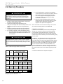
Model Nomenclature
1
2
3
4 5 6
7
8
9
10 11 12
50 Y E W 0 1 0 A W C 3 1 1
Prefix
Packaging
1 = Single Pack, Domestic
Residential Series
Revision Level
YEW = Puron High Temperature
Heating Only Water-to-Water
1 = Current
Voltage
Unit Size
3 = 208-230/60/1
010 (10kW)
Hydronic Options
A = No Pump
B = Load Pump w/Expansion Tank
C = Load Pump & Source Pump(s)
w/Expansion Tanks
Water Coil & DHW Options
C = Copper Source & Braze Plate Load, No DHW
D = Copper Source & Braze Plate Load, DHW w/Sec. hx & pump*
N = Cupro-Nickel Source & Braze Plate Load, No DHW
P = Cupro-Nickel Source & Braze Plate Load, DHW w/Sec. hx & pump*
Controls
W = CXM
Y = CXM w/VSFP
*When digit 9 = “D” or “P,” digit 7 cannot be A.”
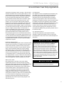
Safety
Warnings, cautions and notices appear throughout this
manual. Read these items carefully before attempting any
installation, service, or troubleshooting of the equipment.
CAUTION: Indicates a potentially hazardous situation or an
unsafe practice, which if not avoided could result in minor or
moderate injury or product or property damage.
DANGER: Indicates an immediate hazardous situation, which
if not avoided will result in death or serious injury. DANGER
labels on unit access panels must be observed.
NOTICE: Notification of installation, operation or maintenance
information, which is important, but which is not hazardrelated.
WARNING: Indicates a potentially hazardous situation, which
if not avoided could result in death or serious injury.
WARNING!
WARNING! Units are shipped with HFC-410A (Puron®)
refrigerant. The Puron® Application and Service Manual
should be read and understood before attempting to
service refrigerant circuits with HFC-410A.
WARNING!
WARNING! All refrigerant discharged from this unit must
be recovered WITHOUT EXCEPTION. Technicians must
follow industry accepted guidelines and all local, state,
and federal statutes for the recovery and disposal of
refrigerants. If a compressor is removed from this unit,
refrigerant circuit oil will remain in the compressor. To
avoid leakage of compressor oil, refrigerant lines of the
compressor must be sealed after it is removed.
WARNING!
WARNING! To avoid the release of refrigerant into the
atmosphere, the refrigerant circuit of this unit must be
serviced only by technicians who meet local, state, and
federal proficiency requirements.
3
50YEW Series Units - 60Hz Puron®
R e v. : 2 1 J u l y, 2 0 1 0
General Information
Inspection
Upon receipt of the equipment, carefully check the shipment
against the bill of lading. Make sure all units have been
received. Inspect the carton or crating of each unit, and
inspect each unit for damage. Assure the carrier makes
proper notation of any shortages or damage on all copies of
the freight bill and completes a common carrier inspection
report. Concealed damage not discovered during unloading
must be reported to the carrier within 15 days of receipt of
shipment. If not filed within 15 days, the freight company can
deny the claim without recourse. Note: It is the responsibility
of the purchaser to file all necessary claims with the carrier.
Notify your equipment supplier of all damage within fifteen
(15) days of shipment.
Storage
Equipment should be stored in its shipping carton in a clean,
dry area. Store units in an upright position at all times. Stack
units a maximum of 3 units high.
Unit Protection
Cover units on the job site with either shipping cartons, vinyl
film, or an equivalent protective covering. Cap the open
ends of pipes stored on the job site. In areas where painting,
plastering, and/or spraying has not been completed, all
due precautions must be taken to avoid physical damage
to the units and contamination by foreign material. Physical
damage and contamination may prevent proper start-up and
may result in costly equipment clean-up.
Examine all pipes, fittings, and valves before installing any of
the system components. Remove any dirt or trash found in
or on these components.
Pre-Installation
Installation, Operation, and Maintenance instructions are
provided with each unit. The installation site chosen should
include adequate service clearance around the unit. Before
unit start-up, read all manuals and become familiar with the
unit and its operation. Thoroughly check the system before
operation.
Prepare units for installation as follows:
1. Compare the electrical data on the unit nameplate with
ordering and shipping information to verify that the
correct unit has been shipped.
2. Keep the cabinet covered with the shipping carton until
installation is complete and all plastering, painting, etc.
is finished.
3. Verify refrigerant tubing is free of kinks or dents and that
it does not touch other unit components.
4. Inspect all electrical connections. Connections must be
clean and tight at the terminals.
5. Locate and verify any HWG or other accessory sensors
located in the compressor section.
4
CAUTION!
CAUTION! DO NOT store or install units in corrosive
environments or in locations subject to temperature or
humidity extremes (e.g., attics, garages, rooftops, etc.).
Corrosive conditions and high temperature or humidity
can significantly reduce performance, reliability, and
service life. Always move and store units in an upright
position. Tilting units on their sides may cause equipment
damage.
CAUTION!
CAUTION! CUT HAZARD - Failure to follow this caution
may result in personal injury. Sheet metal parts may have
sharp edges or burrs. Use care and wear appropriate
protective clothing, safety glasses and gloves when
handling parts and servicing heat pumps.
50YEW Series Units - 60Hz Puron®
R e v. : 2 1 J u l y, 2 0 1 0
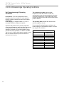
Physical Data
Model
010
Compressor (qty)
Factory Charge HFC-410A (oz) [kg]
1
88 [2.50]
Indoor/Load Water Connection Size
FPT (in)
1
Outdoor/Source Water Connection Size
FPT (in)
1
Domestic Hot Water Connection Size
FPT (in)
3/4
Maximum Working Pressure (Water Side)
Base Unit (PSIG) [kPa]
500 [3445]
DHW Option (PSIG) [kPa]
145 [999]
Internal Source Pump*
w/Expansion Tank (PSIG) [kPa]
45 [310]
Internal Load Pump*
w/Expansion Tank (PSIG) [kPa]
45 [310]
Weight - Operating, (lbs) [kg]
455 [207]
Weight - Packaged, (lbs) [kg]
470 [214]
Dual isolation compressor mounting
Balanced Port Expansion Valve (TXV)
Insulated Source and Load Water Coils
*Does not apply to DHW potable water circuit
5
50YEW Series Units - 60Hz Puron®
R e v. : 2 1 J u l y, 2 0 1 0
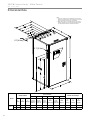
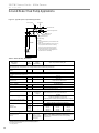
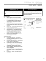
Dimensional Data
Notes:
1. Front, Side, and Top access is preferred for service access.
However, all components may be serviced from the front and
Top access panels if side access is not available.
2. While clear access to all removable panels is not required,
installer should take care to comply with all building codes
and allow adequate clearance for future field service.
1.9” [4.9cm]
2.1” [5.3cm]
Overall Cabinet
Model
010
6
Water Connections
1
2
E
D
Source
Source
(Outdoor) (Outdoor)
Water In Water Out
Electric Access Plugs
3
4
5
6
F
Load
(Indoor)
Water In
G
DHW
Water Out
H
Load
(Indoor)
Water Out
J
DHW
Water In
K
Low
Voltage
L
Low
Voltage
M
Power
Supply
A
Depth
B
Width
C
Height
in.
26.8
25.6
48.9
3.4
8.1
22.3
11.3
17.7
14.4
33.6
35.6
38
cm.
68.1
65.1
124.2
8.6
20.6
56.6
28.7
45
36.6
85.3
90.4
96.5
50YEW Series Units - 60Hz Puron®
R e v. : 2 1 J u l y, 2 0 1 0
Installation
Unit Location
These units are not designed for outdoor installation. Locate
the unit in an INDOOR area that allows enough space for
service personnel to perform typical maintenance or repairs.
The installation of water source heat pump units and all
associated components, parts and accessories which
make up the installation shall be in accordance with
the regulations of ALL authorities having jurisdiction
and MUST conform to all applicable codes. It is the
responsibility of the Installing Contractor to determine
and comply with ALL applicable codes and regulations.
Locate the unit in an indoor area that allows easy removal of
access panels, and has enough space for service personnel
to perform maintenance or repair. Provide sufficient room to
make water and electrical connections. Any access panel
screws that would be difficult to remove after the unit is
installed should be removed prior to setting the unit. These
units are not approved for outdoor installation and, therefore,
must be installed inside the structure being conditioned.
Do not locate in areas where ambient conditions are not
maintained within 40-100°F [4-38°C] and up to 75% relative
humidity.
LOAD PLUMBING INSTALLATION
50YEW Unit Load Plumbing
The applications are too varied to describe in this document,
however some basic guidelines will be presented. All
plumbing should conform to local codes and consider
the following:
Wide temperature variation applications such as
heating/cooling coils
- Employ piping materials that are rated for the
maximum temperature and pressure combination.
This excludes PVC for most heating applications.
- Insure load water flow in high temperature heating
applications is at least 3 gpm per ton [3.2 l/m per kW]
to improve performance and reduce nuisance high
pressure faults.
- DO NOT employ plastic to metal threaded joints
- Utilize a pressure tank and air separator vent
system to equalize pressure and remove air.
Load Piping Connections
Load piping connections are designated ‘Load Water
In and Out’ for the radiant heating system piping, and
‘DHW Water In and Out’ (optional) for connection to the
domestic hot water piping. Any unused piping connections
on the load side of the 50YEW unit will allow spillage of
the load circuit fluid, as the radiant and DHW circuits are
connected internally.
If a unit is ordered with the DHW option and is not being
connected to a radiant heating system, the ‘Load Water
In and Out’ (radiant heating circuit) connections must
be connected to the ‘DHW In and Out’ piping using
tees as shown in Figure 1a. Failure to do so will lead
to nuisance high-pressure faults.
Swimming Pool Hot Tub Applications
- Recommended application includes a brazed plate
heat exchanger to isolate pool water from the unit
heat exchanger.
Potable Water Applications
- Insure load water flow in high temperature heating
applications is at least 3 gpm per ton [3.2 l/m per kW]
to improve performance and reduce nuisance high
pressure faults.
- DHW option includes an internal secondary brazed
plate heat exchanger and bronze circulating pump.
7
50YEW Series Units - 60Hz Puron®
R e v. : 2 1 J u l y, 2 0 1 0
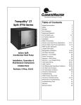
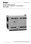
Load Plumbing Installation
Figure 1b: 50YEW Typical Load Piping
+
&
:DWHU+HDWHU
7KHUPLVWRU
1RWH
7R)URP
5DGLDQW)ORRU
5DGLDWRU
%DVHERDUG
RU)DQ&RLO
+HDWLQJ6\VWHP
+
&
'+: '+: +7* +7*
287
,1 287 ,1
+HDWLQJ
%XIIHU7DQN
<(:
8QLW
7KHUPLVWRU
1RWH
8
127(6
3ODFHDLUYHQWDWWKHKLJKHVWSRLQWLQWKHV\VWHP
7KHUPLVWRUVVKRXOGEHLQVWDOOHGLQDQLPPHUVLRQZHOO
/RFDWHWKHUPLVWRULQWKHERWWRPKDOIRIWKHWDQN
37SUHVVXUHWHPSHUDWXUHSRUWVDUHLQWHUQDOIRU
<(:XQLWVRQORDGDQGVRXUFHFRQQHFWLRQV
2WKHUFRPSRQHQWVDGGLWLRQDOEDOOYDOYHVXQLRQVHWF
PD\EHUHTXLUHGIRUHDVHRIVHUYLFH7KLVGUDZLQJ
VKRZVRQO\PLQLPXPUHTXLUHPHQWV<RXUVSHFLILF
LQVWDOODWLRQZLOOGLFWDWHILQDOFRPSRQHQWVHOHFWLRQV
%XIIHUWDQNPXVWEHDSSURYHGDVDKHDWLQJYHVVHO
/RFDOFRGHVXSHUFHGHVDQ\SLSLQJDUUDQJHPHQWVRU
FRPSRQHQWVVKRZQRQWKLVGUDZLQJ
50YEW Series Units - 60Hz Puron®
R e v. : 2 1 J u l y, 2 0 1 0
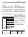
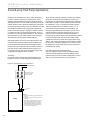
Ground-Water Heat Pump Applications
Typical open loop piping is shown in Figure 2. Shut off valves
should be included in case of servicing. Boiler drains or other
valves should be ‘tee’d’ into the line to allow acid flushing of
just the heat exchanger. Pressure temperature plugs should
be used so that flow and temperature can be measured.
Piping materials should be limited to PVC SCH80 or copper.
Due to the pressure and temperature extremes, PVC
SCH40 is not recommended. Water quantity should be
plentiful and of good quality. Consult Table 2 for water quality
guidelines. The unit can be ordered with either a copper or
cupro-nickel water heat exchanger. Copper is recommended
for closed loop systems and open loop ground water systems
that are not high in mineral content or corrosiveness. In
conditions anticipating heavy scale formation or in brackish
water, a cupro-nickel heat exchanger is recommended. In
ground water situations where scaling could be heavy or
where biological growth such as iron bacteria will be present,
a closed loop system is recommended. Heat exchanger coils
may over time lose heat exchange capabilities due to a build
up of mineral deposits inside. These can be cleaned only by
a qualified service mechanic as acid and special pumping
equipment are required.
Expansion Tank and Pump
Use a closed, bladder-type expansion tank to minimize mineral
formation due to air exposure. The expansion tank should be
sized to handle at least one minute run time of the pump to
prevent premature pump failure using its drawdown capacity
rating. The pump should be sized to the home’s domestic
water load (5-9 gpm [19-34 l/m]) plus the heat pump water
load. Discharge water from the unit is not contaminated in any
manner and can be disposed of in various ways depending
on local building codes; i.e. recharge well, storm sewer, drain
field, adjacent stream or pond, etc. Most local codes forbid the
use of sanitary sewer for disposal. Consult your local building
and zoning department to assure compliance in your area.
Water Control Valve
Note the placement of the water control valve. Always
maintain water pressure in the heat exchanger by placing
water control valves at the outlet of the unit to prevent mineral
precipitation. Pilot operated or Taco slow closing valve’s
solenoid valves are recommended to reduce water hammer.
If water hammer persists, a mini-expansion tank can be
mounted on the piping to help absorb the excess hammer
shock. Insure that the total ‘VA’ draw of the valve can be
supplied by the unit transformer. For instance the Taco slow
closing valve can draw up to 35VA. This can overload smaller
40 or 50 VA transformers depending on the other controls
employed. A typical pilot operated solenoid valve draws
approximately 15VA. Note the special wiring diagram of the
AVM valve (Figure 9).
Flow Regulation
Flow regulation can be accomplished by two methods. First,
most water control valves have a built in flow adjustment.
By measuring the pressure drop through the unit heat
exchanger, flow rate can be determined and compared
to Table 8. Simply adjust the water control valve until the
desired flow is achieved. Secondly, a flow control device may
be installed. The devices are typically an orifice of plastic
material that is designed to allow a specified flow rate. These
are mounted on the outlet of the water control valve. On
occasion, these valves can produce a velocity noise that
can be reduced by applying some back pressure. This is
accomplished by slightly closing the leaving isolation valve of
the well water setup.
Low Temperature Cutout
The water low temperature cutout setpoint should be
activated to avoid freeze damage to the unit. Consult the
low temperature cutout section of the controls description for
instructions.
CAUTION!
CAUTION! Many units are installed with a factory or field
supplied manual or electric shut-off valve. DAMAGE
WILL OCCUR if shut-off valve is closed during unit
operation. A high pressure switch must be installed on the
heat pump side of any field provided shut-off valves and
connected to the heat pump controls in series with the
built-in refrigerant circuit high pressure switch to disable
compressor operation if water pressure exceeds pressure
switch setting. The field installed high pressure switch shall
have a cut-out pressure of 235 psig [1620 kPa] and a cut-in
pressure of 190 psig [1310 kPa]. This pressure switch can
be ordered with a 1/4” internal flare connection as part
number 39B0005N01.
CAUTION!
CAUTION! Refrigerant pressure activated water regulating
valves should never be used with this equipment.
9
50YEW Series Units - 60Hz Puron®
R e v. : 2 1 J u l y, 2 0 1 0
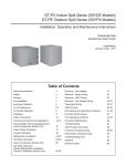
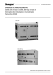
Ground-Water Heat Pump Applications
Figure 2: Typical Open Loop/ Well Application
Strainer (optional)
Flow regulator
From pressure tank
S
To proper discharge location
IN
Shut-off valve
OUT
Water control valve
High Pressure Switch
P/T port
Boiler drain (for flushing)
NOTES:
1. P/T (pressure/temperature) ports are internal for YEW
series units.
2. Other components (additional ball valves, unions, etc.)
may be required for ease of service. This drawing
shows only minimum requirements. Your specific
installation will dictate final component selections.
3. Local code supercedes any piping arrangements or
components shown on this drawing.
50YEW
Source HX
(coaxial)
Sound absorbing pad
Table 2: Water Quality Standards
Water Quality
Parameter
HX
Material
Closed
Recirculating
Open Loop and Recirculating Well
Scaling Potential - Primary Measurement
Above the given limits, scaling is likely to occur. Scaling indexes should be calculated using the limits below
pH/Calcium Hardness
Method
All
-
pH < 7.5 and Ca Hardness <100ppm
Index Limits for Probable Scaling Situations - (Operation outside these limits is not recommended)
Scaling indexes should be calculated at 66°C for direct use and HWG applications, and at 32°C for indirect HX use.
A monitoring plan should be implemented.
Ryznar
6.0 - 7.5
All
Stability Index
If >7.5 minimize steel pipe use.
-0.5 to +0.5
Langelier
All
If <-0.5 minimize steel pipe use. Based upon 66°C HWG and
Saturation Index
Direct well, 29°C Indirect Well HX
Iron Fouling
Iron Fe 2+ (Ferrous)
(Bacterial Iron potential)
All
Iron Fouling
All
-
<0.2 ppm (Ferrous)
If Fe2+ (ferrous)>0.2 ppm with pH 6 - 8, O2<5 ppm check for iron bacteria.
-
<0.5 ppm of Oxygen
Above this level deposition will occur .
Corrosion Prevention
6 - 8.5
pH
All
Hydrogen Sulfide (H2S)
All
Ammonia ion as hydroxide, chloride,
nitrate and sulfate compounds
All
Monitor/treat as
needed
-
6 - 8.5
Minimize steel pipe below 7 and no open tanks with pH <8
<0.5 ppm
At H2S>0.2 ppm, avoid use of copper and copper nickel piping or HX's.
Rotten egg smell appears at 0.5 ppm level.
Copper alloy (bronze or brass) cast components are OK to <0.5 ppm.
-
<0.5 ppm
Maximum Allowable at maximum water temperature.
Maximum
Chloride Levels
Copper
Cupronickel
304 SS
316 SS
Titanium
-
10$C
<20ppm
<150 ppm
<400 ppm
<1000 ppm
>1000 ppm
24$C
NR
NR
<250 ppm
<550 ppm
>550 ppm
38 C
NR
NR
<150 ppm
< 375 ppm
>375 ppm
Erosion and Clogging
Particulate Size and
Erosion
All
<10 ppm of particles
and a maximum
velocity of 1.8 m/s
Filtered for maximum
841 micron [0.84 mm,
20 mesh] size.
Notes:
&ORVHG5HFLUFXODWLQJV\VWHPLVLGHQWLILHGE\Dclosed pressurized piping system.
5HFLUFXODWLQJRSHQZHOOVVKRXOGREVHUYHWKHRSHQUHFLUFXODWLQJGHVLJQFRQVLGHUDWLRQV
15Application not recommended.
1RGHVLJQ0D[LPXP
10
<10 ppm (<1 ppm "sandfree” for reinjection) of particles and a maximum
velocity of 1.8 m/s. Filtered for maximum 841 micron 0.84 mm,
20 mesh] size. Any particulate that is not removed can potentially
clog components.
Rev.: 4/6/2011
50YEW Series Units - 60Hz Puron®
R e v. : 2 1 J u l y, 2 0 1 0
Ground-Loop Heat Pump Applications
Piping Installation
The typical closed loop ground source system is shown in
Figure 3. All earth loop piping materials should be limited to
only polyethylene fusion in inground sections of the loop.
Galvanized or steel fitting should not be used at any time due
to their tendency to corrode. All plastic to metal threaded fittings
should be avoided due to their potential to leak in earth coupled
applications and a flanged fitting substituted. P/T plugs should
be used so that flow can be measured using the pressure drop
of the unit heat exchanger in lieu of other flow measurement
means. Earth loop temperatures can range between 25-110°F
[-3.9 - 43.3°C]. Upon completion of the ground loop piping,
pressure test the loop to assure a leak free system. Horizontal
Systems: test individual loops as installed. Test entire system
when all loops are assembled.
Vertical U-Bends and Pond Loop Systems: test vertical
U-bends and pond loop assemblies prior to installation with a
hydrostatic test pressure of at least 100 psi [689 kPa].
Table 3: Approximate Fluid Volume (gal.) per 100' of Pipe
Fluid Volume (gal [liters] per 100’ [30 meters) Pipe)
Pipe
Copper
Rubber Hose
Polyethylene
Size
Volume (gal) [liters]
1”
4.1 [15.3]
1.25”
6.4 [23.8]
2.5”
9.2 [34.3]
1”
3.9 [14.6]
3/4” IPS SDR11
2.8 [10.4]
1” iPS SDR11
4.5 [16.7]
1.25” IPS SDR11
8.0 [29.8]
1.5” IPS SDR11
10.9 [40.7]
2” IPS SDR11
18.0 [67.0]
1.25” IPS SCH40
8.3 [30.9]
1.5” IPS SCH40
10.9 [40.7]
2” IPS SCH40
17.0 [63.4]
Unit Heat Exchanger
Typical
1.0 [3.8]
Flush Cart Tank
10” Dia x 3ft tall
[254mm x 91.4cm tall]
10 [37.9]
Flushing the Earth Loop
Once piping is completed between the unit, flow center and
the ground loop (Figure 3), final purging and charging of the
loop is needed. A flush cart (at least a 1.5 hp [1.1 kW] pump)
is needed to achieve adequate flow velocity in the loop to
purge air and dirt particles from the loop itself. An antifreeze
solution is used in most areas to prevent freezing. All air and
debris must be removed from the earth loop piping system
before operation. Flush the loop with a high volume of water
at a high velocity (2 fps [0.6 m/s] in all piping) both directions.
The steps below must be followed for proper flushing. Fill loop
with water from a garden hose through flush cart before using
flush cart pump to ensure an even fill. Once full, do not allow
the water level in the flush cart tank to drop below the pump
inlet line or air can be pumped back out to the earth loop. Try
to maintain a fluid level in the tank above the return tee so
that air can not be continuously mixed back into the fluid. 50
psi [345 kPa] surges can be used to help purge air pockets
by simply shutting off the return valve going into the flush cart
reservoir. This ‘dead heads’ the pump to 50 psi [345 kPa].
To dead head the pump until maximum pumping pressure is
reached, open the valve back up and a pressure surge will
be sent through the loop to help purge air pockets from the
piping system. Notice the drop in fluid level in the flush cart
tank. If air is purged from the system, the level will drop
only 1-2 [25-50mm] inches in a 10” [254mm] diameter
PVC flush tank (about a half gallon) since liquids are
incompressible. If the level drops more than this, flushing
should continue since air is still being compressed in the loop
fluid. Do this a number of times.
When the fluid level drops less than 1-2” [25-50mm] in a 10”
[254mm] diameter tank the flow can be reversed. Finally the
dead head test should be checked again for an indication
of air in the loop. This fluid level drop is your only
indication of air in the loop.
Table 4: Antifreeze Percentages by Volume
Type
Minimum Temperature for Low Temperature Protection
10°F [-12.2°C]
15°F [-9.4°C]
20°F [-6.7°C]
25°F [-3.9°C]
25%
38%
29%
21%
25%
25%
16%
22%
20%
10%
15%
14%
Methanol
100% USP food grade Propylene Glycol
Ethanol*
* Must not be denatured with any petroleum based product
11
50YEW Series Units - 60Hz Puron®
R e v. : 2 1 J u l y, 2 0 1 0
Ground-Loop Heat Pump Applications
Antifreeze may be added before, during, or after the flushing
procedure. However, depending upon which time is chosen,
antifreeze could be wasted when emptying the flush cart tank.
See antifreeze section for more details. Loop static pressure will
fluctuate with the seasons. Pressures will be higher in the winter
months than during the cooling season. This fluctuation is normal
and should be considered when charging the system initially.
Run the unit in either heating or cooling for a number of minutes
to condition the loop to a homogenous temperature. This is a
good time for tool cleanup, piping insulation etc. Then final flush
and pressurize the loop to a static pressure of 40-50 psi [275345 kPa] (winter) 15-20 psi [100-138 kPa] (summer).
After pressurization, be sure to remove the plug in the end
of the Grundfos loop pump motor(s) to allow trapped air to
be discharged and to insure the motor housing has been
flooded. This is not required for Taco circulators. Insure the
loop flow center provides adequate flow through the unit
by checking pressure drop across the heat exchanger and
comparing it to the figures shown in Table 8.
Antifreeze
In areas where minimum entering loop temperatures drop
below 40°F [4.4°C] or where piping will be routed through
Figure 3: Typical Earth Loop Connection.
7R)URP*URXQG/RRS
2SWLRQDO)ORZ&RQWUROOHU
IRUXQLWVQRWHTXLSSHG
ZLWKDQLQWHUQDOSXPS
)ORZ&RQWUROOHU
37SRUW
,1
<(:
6RXQGDEVRUELQJSDG
12
287
127(6
37SUHVVXUHWHPSHUDWXUHSRUWVDUHLQWHUQDOIRU<(:
VHULHVXQLWV
6RXUFHZDWHUSLSLQJPXVWEHLQVXODWHGIRUFORVHGORRS
LQVWDOODWLRQV
2WKHUFRPSRQHQWVDGGLWLRQDOEDOOYDOYHVXQLRQVHWF
PD\EHUHTXLUHGIRUHDVHRIVHUYLFH7KLVGUDZLQJ
VKRZVRQO\PLQLPXPUHTXLUHPHQWV<RXUVSHFLILF
LQVWDOODWLRQZLOOGLFWDWHILQDOFRPSRQHQWVHOHFWLRQV
/RFDOFRGHVXSHUFHGHVDQ\SLSLQJDUUDQJHPHQWVRU
FRPSRQHQWVVKRZQRQWKLVGUDZLQJ
areas subject to freezing, antifreeze is needed. Alcohols and
glycols are commonly used as antifreezes, however your
local territory manager should be consulted for the antifreeze
best suited to your area. Low temperature protection should
be maintained to 15°F [-9.4°C] below the lowest expected
entering loop temperature. For example, if 30°F [-1.1°C]
is the minimum expected entering loop temperature, the
leaving loop temperature would be 25-22°F [-3.9 to -5.6°C]
and low temperature protection should be at 15°F [-9.4°C]
(30°F-15°F=15°F). All alcohols should be premixed and
pumped from a reservoir outside of the building when possible
or introduced under water level to prevent fuming. Initially
calculate the total volume of fluid in the piping system using
Table 3. Then use the percentage by volume shown in Table 4
for the amount of antifreeze. Antifreeze concentration should
be checked from a well mixed sample using a hydrometer to
measure specific gravity.
Low Water Temperature Cut-Out Setting
When an antifreeze is selected the low temperature limit
setpoint should be switched to the lower setting to avoid
nuisance faults. Consult Low Water Temperature Cut-Out
Setting in the controls section for more information.
50YEW Series Units - 60Hz Puron®
R e v. : 2 1 J u l y, 2 0 1 0
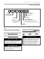
Electrical - Line Voltage
General Line Voltage Wiring
Be sure the available power is the same voltage and phase as
that shown on the unit serial plate. Line and low voltage wiring
must be done in accordance with local codes or the National
Electric Code, whichever is applicable.
WARNING!
WARNING! To avoid possible injury or death due to
electrical shock, open the power supply disconnect switch
and secure it in an open position during installation.
50YEW Power Connection
Line voltage connection is made by connecting the incoming
line voltage wires to the power block as shown in Figure 4.
Consult Table 5 or unit data plate for correct fuse size.
CAUTION!
CAUTION! Use only copper conductors for field
installed electrical wiring. Unit terminals are not
designed to accept other types of conductors.
All field installed wiring, including electrical ground, must
comply with the National Electrical Code as well as all
applicable local codes.
General Line Voltage Wiring
Be sure the available power is the same voltage and phase as
that shown on the unit serial plate. Line and low voltage wiring
must be done in accordance with local codes or the National
Electric Code, whichever is applicable.
Refer to the unit wiring diagrams for fuse sizes and a
schematic of the field connections which must be made by
the installing (or electrical) contractor.
Consult the unit wiring diagram located on the inside of the
compressor access panel to ensure proper electrical hookup.
50YEW Power Connection
Line voltage connection is made by connecting the incoming
line voltage wires to the power block as shown in Figure 4.
Consult Table 5 for correct fuse size.
All final electrical connections must be made with a length of
flexible conduit to minimize vibration and sound transmission
to the building.
208 Volt Operation
All 208-240 Volt units are factory wired for 240 Volt. The
transformers may be switched to 208V operation as illustrated
on the wiring diagram. By switching the Red (208V) and the
Orange (240V) at the terminal.
Table 5: Electrical Data
Units with DHW Option
Model
50YEW010
Voltage
Code
Voltage
G
208-230/60/1
Min/Max
Voltage
197/254
Compressor
*Load
*Source
Qty
RLA
LRA
Pump
FLA
Pump
FLA
1
20.7
81
ISBP
Pump
FLA
Total
Unit
FLA
Min
Circuit
Amps
Max
Fuse
HACR
1.07
-
1.07
22.8
28
45
1.07
1.07
1.07
23.9
29.1
45
Total
Unit
FLA
Min
Circuit
Amps
Max
Fuse
HACR
Standard (No DHW)
Model
50YEW010
Voltage
Code
Voltage
G
208-230/60/1
Min/Max
Voltage
197/254
Compressor
*Load
*Source
Qty
RLA
LRA
Pump
FLA
Pump
FLA
-
-
20.7
25.9
45
1
20.7
81
1.07
-
21.8
26.9
45
1.07
1.07
22.8
28
45
*Denotes optional items. Consult unit data plate if configuration is unknown.
13
50YEW Series Units - 60Hz Puron®
R e v. : 2 1 J u l y, 2 0 1 0
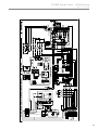
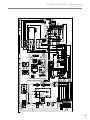
Electrical - Line Voltage
Figure 4: 50YEW 60Hz Line and Low Voltage
Field Low Voltage Wiring
14
Field Line Voltage Wiring
50YEW Series Units - 60Hz Puron®
R e v. : 2 1 J u l y, 2 0 1 0
Electrical - Low Voltage
Low Voltage Connections
The thermistors (sensors) and other low voltage wiring
should be connected to the 12 position terminal strip in the
50YEW control box. See figures 4 and unit wiring diagram
for details.
Thermistors (one each) for the buffer tank, outdoor air and
DHW storage tank (if equipped with the DHW option) are
coiled and shipped loose in the unit.
Low Water Temperature Cutout - FP1
The CXM/DXM control allows the field selection of source fluid
low temperature cutout points. The factory setting of FP1 is
set for water (30°F [-1.1°C]). In cold temperature applications
jumper JW3 (FP1- antifreeze 10°F [-12.2°C]) should be clipped
as shown in Figure 5 to change the setting to 10°F [-12.2°C], a
more suitable temperature when using antifreezes.
"A" has been provided to control accessory devices, such as
water valves, electronic air cleaners, humidifiers, etc. Note:
This terminal should be used only with 24 Volt signals
and not line voltage signals. This signal operates with the
compressor contactor. See Figure 6 or the wiring schematic
for details.
Figure 6: Accessory Wiring
CXM
Board
Accessory Connections
A terminal paralleling the compressor contactor coil has
been provided on the CXM/DXM control of the 50YEW unit.
Figure 5: Changing FP1-Low Water Temperature Cutout
Setpoint
JW3-FP1 jumper
should be clipped
when antifreeze
is used.
CXM Board
Water Solenoid Valves
Figures 7a and 7b illustrate a typical slow closing water
control valve wiring. A slow closing valve may be required
to prevent water hammer. When using an AVMB -Taco Slow
Closing valves on 50YEW Series equipment Figure 9a wiring
should be utilized. The valve takes approximately 60 seconds
to open (very little water will flow before 45 seconds) and it
activates the compressor only after the valve is completely
opened (by closing its end switch). Only relay or triac based
electronic thermostats should be used with the AVMB valve.
When wired as shown, the valve will operate properly with
the following notations:
1. The valve will remain open during a unit lockout.
2. The valve will draw approximately 25-35 VA through the “Y”
signal of the thermostat.
15
50YEW Series Units - 60Hz Puron®
R e v. : 2 1 J u l y, 2 0 1 0
Electrical - Low Voltage
Figure 7a: Well Water AVMB Valve Wiring
CAUTION!
CAUTION! Many units are installed with a factory or field
supplied manual or electric shut-off valve. DAMAGE
WILL OCCUR if shut-off valve is closed during unit
operation. A high pressure switch must be installed on the
heat pump side of any field provided shut-off valves and
connected to the heat pump controls in series with the
built-in refrigerant circuit high pressure switch to disable
compressor operation if water pressure exceeds pressure
switch setting. The field installed high pressure switch shall
have a cut-out pressure of 235 psig [1620 kPa] and a cut-in
pressure of 190 psig [1310 kPa]. This pressure switch can
be ordered with a 1/4” internal flare connection as part
number 39B0005N01.
CXM Board*
Y
R
2
1
Heater
3
Switch
AVMB
Taco Valve
Y1
MPC*
CAUTION!
*Valve must be wired in between the CXM and MPC boards. Remove the yellow
wire from the CXM board and connect it to terminal 2 on the valve. Add a new
wire from terminal 3 to the Y terminal at the CXM board, and a jumper wire from
terminal 1 to terminal R at the CXM board as shown above.
Figure 7b: Taco SBV Valve Wiring
C
Y1
Y*
MPC*
CXM
Board
Taco SBV Valve
*Valve must be wired in between the CXM and MPC boards. Remove the yellow
wire from the CXM board and connect it to the w/y terminal on the valve. Add a
new wire from the end switch (bottom connection) to the the Y terminal at the
CXM board, and a jumper wire from the w/y terminal to the other side (top
connection) of the end switch as shown above.
16
CAUTION! Refrigerant pressure activated water regulating
valves should never be used with this equipment.
50YEW Series Units - 60Hz Puron®
R e v. : 2 1 J u l y, 2 0 1 0
Electrical - Controls
Controls
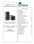
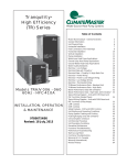
User interface: Figure 8 shows the factory installed and
wired panel-mounted user interface for customizing the
MPC programming. A large dot-matrix style 2” x 2” [5 x 5
cm] back-lit display is controlled by four arrow keys and a
select key. The main screen, as shown in figure 9, displays
current outdoor and water temperatures, and allows the
user to change settings by selecting one of the menus
from the bottom of the screen (see figure 11 50YEW User
Interface Menu). A special installer set up mode allows the
technician to change some of the default MPC parameters.
The installer menu may only be accessed when the unit is
placed in the off mode. Holding the up and down buttons at
the same time will cause the interface to enter the installer
setup mode. See figure 12 (interface installer menu) The
user interface includes a time schedule for DHW generation,
Fahrenheit/Celsius selection, vacation mode for DHW, and
other user preference options.
50YEW Series Control Features
The advantage of a programmable controller, as outlined
above, is the ability to integrate complex decision-making
tasks with the standard heat pump (CXM) controls and
communicate with a user interface. Below is a list of
standard features that are included in the 50YEW series
controls.
CAUTION!
CAUTION: Maximum leaving water temperature of the
YEW series equipment is 145°F [63°C]. For domestic
hot water tank temperatures or heating buffer tank
temperatures above 130°F [54°C], pump and pipe sizing is
critical to insure that the flow rate through the heat pump
is sufficient to maintain leaving water temperatures below
the maximum temperature, and to provide water flow
rates within the ranges shown in the performance section
of this manual.
Figure 8: 50YEW User Interface
Arrow Keys
Select Key
Outdoor temperature reset: The heat pump capacity and
water temperature delivery to the heating system must
be designed for local weather conditions, usually at the
99.6% outdoor temperature. Therefore, 99.6% of the
heating season, the heating load is less than it is at design
conditions. As the outdoor temperature decreases, the
heat loss of the structure increases, which requires more
capacity from the heating system. If the water temperature
is reduced as the outdoor air temperature increases (and
vise-versa), the heat pump operates at higher COP most of
the year. The MPC has a built in algorithm that adjusts the
buffer tank temperature based upon outdoor air temperature
to maximize efficiency and comfort. Temperature settings
may be adjusted at the user interface if factory defaults are
not sufficient.
Figure 9: 50YEW User Interface Main Screen
The base setpoint for energizing the compressor in the
heating mode is determined by subtracting one-half the
heating differential value (HTD) from the buffer tank heating
temperature setpoint. The HTD is the differential used for
controlling setpoint. For example, if the buffer tank setpoint
is 100°F [38°C], and the HTD is 6°F [3°C], the compressor
will be energized at 97°F [36°C] and will be turned off
at 103°F [39°C]. The HTD is the difference between the
compressor “call” (97°F [36°C]) and the “satisfied” (103°F
[39°C]) temperature. The buffer tank temperature may then
be reduced by the outdoor temperature reset function,
depending on the current outdoor air temperature (OAT)
value. The valid range for the buffer tank heating setpoint is
70-140°F [21-60°C], with a default value of 100°F [38°C]. The
valid range for the heating differential value (HTD) is 4-20°F
[2-11°C], adjustable in 2°F [1°C] increments, with a default
value of 6°F [3°C].
17
50YEW Series Units - 60Hz Puron®
R e v. : 2 1 J u l y, 2 0 1 0
Electrical - Controls
There are four outdoor reset variables used for reducing the
buffer tank setpoint. The outdoor design temperature (ODT)
is the OAT above which setpoint reduction begins. The
valid range for ODT is –40°F to 50°F [-40°C to 10°C], with
a default value of 0°F [-18°C]. The maximum design buffer
tank temperature (MaxBT) is the maximum desired buffer
tank setpoint at the outdoor design temperature. The valid
range for MaxBT is 80-140°F [27-60°C], with a default value
of 130°F [54°F]. The building balance point temperature
(the temperature at which heating is no longer needed) is
the OAT at which maximum setpoint (MaxBT) reduction will
occur. The valid range for building balance point is 50-70°F
[10-21°C], with a default value of 60°F [16°F]. The minimum
Table 6: Buffer Tank Interface Inputs
Setting Description
Range
Default
Buffer Tank Set Point
70-140°F [21-60°C}
100°F [38°C]
Buffer Tank Deadband
4-20°F [2-11°C]
6°F [3°C]
Outdoor Design Temp
-40-50°F [-40-10°C]
0°F [-18°C]
Maximum Design
Water Temp
80-140°F [27-60°C]
130°F [54°C]
Minimum Design
Water Temp
70-120°F [21-49°C]
70°F [21°C]
Building Balance
Point Temp
50-70°F [10-21°C]
60°F [16°C]
The maximum design water temperature must be equal the buffer
tank setpoint. The buffer tank setpoint will override the maximum
design temperature if they are entered with different values.
design water temperature is the minimum desired buffer tank
setpoint at the building balance point temperature. The valid
range for minimum buffer tank temperature is 70°F-120°F
[21-49°C], with a default value of 70°F [21°c]. If an OAT
sensor is not detected (or if a thermistor error has occurred),
the buffer tank setpoint will not be reduced based on the
OAT value (i.e. the controller will use the buffer tank setpoint
as described in the previous paragraph).
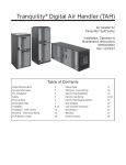
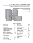
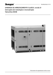
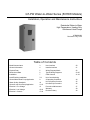
Figure 10 shows an example outdoor temperature reset
curve for a climate that has an outdoor design temperature
of -4°F [-20°C]. At design temperature, the radiant floor
system needs 126°F [52°C] water. However, when the
outdoor temperature is 68°F [20°C], the home needs no
heating (building balance point). In between -4°F and 68°F
[-20°C and 20°C], the water temperature in the buffer tank
is adjusted accordingly. For homes that are well insulated
and tightly sealed, the building balance point may be 55°F
[13°C] or lower, so the slope of the line changes based
upon settings at the user interface. The radiant floor design
temperature will also change the slope of the line. If tighter
pipe spacing is used, for example, the water temperature at
the outdoor design temperature may only be 100°F [38°C].
Again, as the settings are changed at the user interface,
the slope of the line will change. As mentioned earlier, the
lower the heating water temperature at design conditions,
the higher the efficiency (COP) of the heat pump. The
combination of a lower design temperature and outdoor
temperature reset can result in a significant impact on
operating costs.
Buffer Tank Temperature, °C [°F]
Figure 10: Example Outdoor Temperature Reset
55
52ºC [126ºF]
[131]
50
[122]
45
[113]
40
[104]
35
[95]
30
Maximum
Buffer Tank
Temperature
Minimum
Buffer Tank
Temperature
[86]
Outdoor
Design
Temperature
25
[77]
20
20ºC [68ºF]
[68]
15
[59]
10
[50]
30
[86]
25
[77]
20
[68]
Building
Balance
Point
Temperature
15
[59]
10
[50]
5
[41]
0
[32]
-5
[23]
-10
[14]
-15
Outdoor Temperature, °C [°F]
18
[5]
-20
[-4]
-25
[-13]
-30
[-22]
50YEW Series Units - 60Hz Puron®
R e v. : 2 1 J u l y, 2 0 1 0
Electrical - Controls
Warm weather shutdown (WWSD): Radiant floor systems
are the most comfortable type of heating available today.
However, they do have one disadvantage – quickly switching
from heating to cooling is not possible due to the mass heat
storage in the slab. For example, in the spring or fall, there
could be times where heating is required at night, but cooling
is required during the day. With a warm floor, the cooling
system has to work much harder to cool the space. WWSD
shuts down the water-to-water heat pump at a pre-determined
outdoor air temperature (adjustable at the user interface).
When a water-to-air heat pump is used for space cooling,
this unit can be enabled when WWSD is activate, allowing
the water-to-air heat pump to heat via forced air during the
shoulder seasons, avoiding the warm slab/cooling dilemma
(see cooling enable, below). A normally closed contact is
provided in the 50YEW unit to de-energize the heating system
controls (e.g. radiant floor control panel) during WWSD.
WWSD does not affect DHW heating. In other words, the
water-to-water unit can still operate for generating DHW, even
if the heating distribution (e.g. radiant floor) system is disabled.
The WWSD activation (i.e. when the WWSD feature is
enabled) outdoor air temperature range is 40-100°F [4-38°C]
with a default value of 70°F [21°C]. The WWSD deactivation
(i.e. when the radiant heating returns to operating mode)
temperature range is 35-95°F [2-35°C] with a default value
of 65°F [18°C] and a minimum difference between activation
and deactivation temperatures of 5°F [3°C]. If the outdoor air
temperature (OAT) rises above the activation temperature, the
cooling enable signal (see below) is enabled, and the control
no longer controls the buffer tank temperature. If the OAT
falls below the deactivation temperature, the control resumes
monitoring the buffer tank temperature.
Cooling enable: Cooling enable is tied to the WWSD feature.
If desired, the water-to-air unit controls can be wired to the
50YEW unit controls, which will allow the water-to-air unit
to operate during WWSD, but will disable the water-to-air
unit when the 50YEW unit is not in WWSD mode. When a
heat pump thermostat is connected to the water-to-air unit,
forced air heating may be used for the shoulder seasons,
allowing quick heating to cooling changeover. If this feature
is used, the consumer will easily be able to tell when WWSD
is enabled because the water-to-air unit thermostat will only
be active during WWSD. Otherwise, the water-to-air unit
thermostat will be disabled, indicating that the consumer
should utilize the hydronic heating (e.g. radiant floor)
thermostat.
DHW priority: By default, DHW heating always takes priority
over space heating. Normally, the hot water load will be
satisfied quickly, and the unit can then switch back to space
heating.
Time schedule: DHW temperatures may be adjusted
during occupied/unoccupied times via the user interface to
save energy costs.
Vacation mode: DHW generation may be disabled when the
user interface is placed in vacation mode. A return date and
time may be set to restore normal DHW temperatures.
Emergency DHW generation: If the 50YEW unit is locked out,
a 24VAC signal can be sent to a contactor at the water heater
to allow the operation of the electric elements and associated
thermostat.
Enhanced heat pump lockouts: The CXM board locks out
the compressor any time a lockout condition occurs. The
MPC reads the lockouts from the CXM, and reports the
condition to the user interface. The user interface changes
from a blue backlight to a red backlight, indicating a lockout.
The actual lockout is reported (e.g. High Pressure) at the
interface. In addition to the standard CXM faults, the MPC
checks for bad thermistors and high compressor discharge
temperature, which are also reported at the user interface.
Pump control: If the optional load and source pump(s) are
selected, the control energizes the pumps any time the
compressor is operating.
Variable speed floor pump (VSFP) output: Some radiant floor
systems utilize a variable speed pump on the floor system,
which changes flow based upon the number of zones open
or closed. Since the pump has built-in controls, only a power
supply is needed. An optional power terminal is available for
VSFP applications.
Second stage heating (backup boiler): Optimal heat pump
sizing may not include a water-to-water heat pump that
can handle 100% of the heating load. When a backup
boiler is used to supplement the heating capacity, a 24VAC
output from the 50YEW unit can energize the boiler. The
boiler control box simply needs a relay that can be used to
interface with the 50YEW unit.
19
50YEW Series Units - 60Hz Puron®
R e v. : 2 1 J u l y, 2 0 1 0
Electrical - Controls
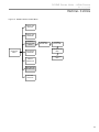
Figure 11: 50YEW User Interface Menu
DAYLIGHT
SAVINGS
SET DATE
AND TIME
SET MONTH,
DAY, YR, HR, MIN
VACATION
HOLD DATE
THEN TIME
MAIN SCREEN
PROGRAM
MENU
MAIN MENU
PROGRAM
SETTINGS
MODE
EVENTS
PER DAY
2ND STAGE
HEAT
WM. WEATHER
SHUTDOWN
F OR C
PROGRAM
SCREEN
12 OR 24 HOUR
CLOCK
SCREEN
SETTINGS
LANGUAGE
CONTRAST
TEMPERATURE
OFFSETS
BACKLIGHT
TEMP ADJUST
LOCKOUT
SECURITY
LOCKOUT
TOTAL KEYPAD
LOCKOUT
SERVICE
INFORMATION
FAULT
STATUS
TEMPERATURE
STATUS
CLEAR FAULT
HISTORY
OPERATING
MODE
20
FAULT
DESCRIPTION
50YEW Series Units - 60Hz Puron®
R e v. : 2 1 J u l y, 2 0 1 0
Electrical - Controls
Figure 12: 50YEW Interface Installer Menu
BUFFER TANK
SETPOINT
BUFFER TANK
DEADBAND
OUTDOOR
TEMPERATURE
RESET
INSTALLER
MENU
HOT WATER
DEADBAND
OUTDOOR
DESIGN TEMP
MAXIMUM
WATER TEMP
MINIMUM WATER
TEMP
BALANCE POINT
TEMP
MANUAL
OPERATION
INPUT DEALER
INFORMATION
RESTORE
DEFAULTS
21
50YEW Series Units - 60Hz Puron®
R e v. : 2 1 J u l y, 2 0 1 0
Electrical - Wiring Diagram Matrix
22
Model
Diagram
Number
Voltage
Option
50YEW
96B0108N05
230/60/1
-
50YEW
96B0108N06
230/60/1
VSFP
50YEW
96B0108N08
230/60/1
DHW
50YEW
96B0108N09
230/60/1
DHW + VSFP
50YEW Series Units - 60Hz Puron®
R e v. : 2 1 J u l y, 2 0 1 0
Typical Wiring Diagram - 50YEW 230/60/1 Units
23
50YEW Series Units - 60Hz Puron®
R e v. : 2 1 J u l y, 2 0 1 0
Typical Wiring Diagram - 50YEW 230/60/1 Units
24
50YEW Series Units - 60Hz Puron®
R e v. : 2 1 J u l y, 2 0 1 0
Typical Wiring Diagram - 50YEW 230/60/1 Units With VSFP
25
50YEW Series Units - 60Hz Puron®
R e v. : 2 1 J u l y, 2 0 1 0
Typical Wiring Diagram - 50YEW 230/60/1 Units With VSFP
26
50YEW Series Units - 60Hz Puron®
R e v. : 2 1 J u l y, 2 0 1 0
27
50YEW Series Units - 60Hz Puron®
R e v. : 2 1 J u l y, 2 0 1 0
28
50YEW Series Units - 60Hz Puron®
R e v. : 2 1 J u l y, 2 0 1 0
29
50YEW Series Units - 60Hz Puron®
R e v. : 2 1 J u l y, 2 0 1 0
30
50YEW Series Units - 60Hz Puron®
R e v. : 2 1 J u l y, 2 0 1 0
CXM Control
CXM Control
For detailed control information, see CXM Application,
Operation and Maintenance (AOM) manual (part #
97B0003N12.
Field Selectable Inputs
Test mode: Test mode allows the service technician to
check the operation of the control in a timely manner.
By momentarily shorting the test terminals, the CXM
control enters a 20 minute test mode period in which all
time delays are sped up 15 times. Upon entering test
mode, the status LED will flash a code representing
the last fault. For diagnostic ease at the thermostat,
the alarm relay will also cycle during test mode. The
alarm relay will cycle on and off similar to the status
LED to indicate a code representing the last fault, at the
thermostat. Test mode can be exited by shorting the
test terminals for 3 seconds.
Retry Mode: If the control is attempting a retry of a
fault, the status LED will slow flash (slow flash = one
flash every 2 seconds) to indicate the control is in the
process of retrying.
Field Configuration Options
Note: In the following field configuration options,
jumper wires should be clipped ONLY when power is
removed from the CXM control.
On = Enabled. Off = Disabled.
DIP switch 2: Stage 2 Selection - provides selection of
whether compressor has an “on” delay. If set to stage
2, the compressor will have a 3 second delay before
energizing. Also, if set for stage 2, the alarm relay will
NOT cycle during test mode.
On = Stage 1. Off = Stage 2
DIP switch 3: Not Used.
DIP switch 4: DDC Output at EH2 - provides selection
for DDC operation. If set to “DDC Output at EH2,” the
EH2 terminal will continuously output the last fault
code of the controller. If set to “EH2 normal,” EH2 will
operate as standard electric heat output.
On = EH2 Normal. Off = DDC Output at EH2.
NOTE: Some CXM controls only have a 2 position DIP
switch package. If this is the case, this option can be
selected by clipping the jumper which is in position 4
of SW1.
Jumper not clipped = EH2 Normal. Jumper clipped =
DDC Output at EH2.
DIP switch 5: Factory Setting - Normal position is
“On.” Do not change selection unless instructed to do
so by the factory.
Table 6a: CXM LED And Alarm Relay Operations
Description of Operation
LED
Alarm Relay
Normal Mode
Normal Mode with UPS Warning
CXM is non-functional
Fault Retry
Lockout
Over/Under Voltage Shutdown
On
On
Off
Slow Flash
Fast Flash
Slow Flash
Open
Cycle (closed 5 sec., Open 25 sec.)
Open
Open
Closed
Open (Closed after 15 minutes)
Test Mode - No fault in memory
Flashing Code 1
Cycling Code 1
Test Mode - HP Fault in memory Flashing Code 2
Cycling Code 2
Test Mode - LP Fault in memory
Flashing Code 3
Cycling Code 3
Test Mode - FP1 Fault in memory Flashing Code 4
Cycling Code 4
Test Mode - FP2 Fault in memory Flashing Code 5
Cycling Code 5
Test Mode - CO Fault in memory Flashing Code 6
Cycling Code 6
Test Mode - Over/Under
shutdown in memory
Flashing Code 7
Cycling Code 7
Not Clipped = 30°F [-1°C]. Clipped = 10°F [-12°C].
Test Mode - UPS in memory
Flashing Code 8
Cycling Code 8
Alarm relay setting: Jumper 1 (JW1-AL2 Dry) provides
field selection of the alarm relay terminal AL2 to
be jumpered to 24VAC or to be a dry contact (no
connection).
Test Mode - Swapped Thermistor Flashing Code 9
Cycling Code 9
Water coil low temperature limit setting: Jumper
3 (JW3-FP1 Low Temp) provides field selection of
temperature limit setting for FP1 of 30°F or 10°F [-1°F
or -12°C] (refrigerant temperature).
Not Clipped = 30°F [-1°C]. Clipped = 10°F [-12°C].
Air coil low temperature limit setting: Jumper 2 (JW2FP2 Low Temp) provides field selection of temperature
limit setting for FP2 of 30°F or 10°F [-1°F or -12°C]
(refrigerant temperature). Note: This jumper should
only be clipped under extenuating circumstances, as
recommended by the factory.
Not Clipped = AL2 connected to R. Clipped = AL2 dry
contact (no connection).
DIP Switches
Note: In the following field configuration options, DIP
switches should only be changed when power is
removed from the CXM control.
DIP switch 1: Unit Performance Sentinel Disable provides field selection to disable the UPS feature.
-Slow Flash = 1 flash every 2 seconds
-Fast Flash = 2 flashes every 1 second
-Flash code 2 = 2 quick flashes, 10 second pause, 2 quick
flashes, 10 second pause, etc.
-On pulse 1/3 second; off pulse 1/3 second
CAUTION!
CAUTION! Do not restart units without inspection and
remedy of faulting condition. Equipment damage may
occur.
31
50YEW Series Units - 60Hz Puron®
R e v. : 2 1 J u l y, 2 0 1 0
Safety Features - CXM Control
Safety Features – CXM Control
The safety features below are provided to protect
the compressor, heat exchangers, wiring and other
components from damage caused by operation
outside of design conditions.
Anti-short cycle protection: The control features a 5
minute anti-short cycle protection for the compressor.
Note: The 5 minute anti-short cycle also occurs at power
up.
Random start: The control features a random start
upon power up of 5-80 seconds.
Fault Retry: In Fault Retry mode, the Status LED
begins slowly flashing to signal that the control is
trying to recover from a fault input. The control will
stage off the outputs and then “try again” to satisfy
the thermostat input call. Once the thermostat input
call is satisfied, the control will continue on as if no
fault occurred. If 3 consecutive faults occur without
satisfying the thermostat input call, the control will go
into “lockout” mode. The last fault causing the lockout
will be stored in memory and can be viewed at the
“fault” LED (DXM board) or by going into test mode
(CXM board). Note: FP1/FP2 faults are factory set at
only one try.
Lockout: In lockout mode, the status LED will begin
fast flashing. The compressor relay is turned off
immediately. Lockout mode can be “soft” reset by
turning off the thermostat (or satisfying the call). A
“soft” reset keeps the fault in memory but resets the
control. A “hard” reset (disconnecting power to the
control) resets the control and erases fault memory.
Lockout with emergency heat: While in lockout mode,
if W becomes active (CXM), emergency heat mode will
occur.
High pressure switch: When the high pressure switch
opens due to high refrigerant pressures, the compressor
relay is de-energized immediately since the high pressure
switch is in series with the compressor contactor coil.
The high pressure fault recognition is immediate (does not
delay for 30 continuous seconds before de-energizing the
compressor).
High pressure lockout code = 2
Example: 2 quick flashes, 10 sec pause, 2 quick
flashes, 10 sec. pause, etc.
Low pressure switch: The low pressure switch must be
open and remain open for 30 continuous seconds during
“on” cycle to be recognized as a low pressure fault. If
the low pressure switch is open for 30 seconds prior to
compressor power up it will be considered a low pressure
(loss of charge) fault. The low pressure switch input is
32
bypassed for the initial 120 seconds of a compressor run
cycle.
Low pressure lockout code = 3
Water coil low temperature (FP1): The FP1 thermistor
temperature must be below the selected low
temperature limit setting for 30 continuous seconds
during a compressor run cycle to be recognized as a
FP1 fault. The FP1 input is bypassed for the initial 120
seconds of a compressor run cycle. FP1 is set at the
factory for one try. Therefore, the control will go into
lockout mode once the FP1 fault has occurred.
FP1 lockout code = 4
Air coil low temperature (FP2): The FP2 thermistor
temperature must be below the selected low
temperature limit setting for 30 continuous seconds
during a compressor run cycle to be recognized as a
FP2 fault. The FP2 input is bypassed for the initial 60
seconds of a compressor run cycle. FP2 is set at the
factory for one try. Therefore, the control will go into
lockout mode once the FP2 fault has occurred.
FP2 lockout code = 5
Condensate overflow: The condensate overflow sensor
must sense overflow level for 30 continuous seconds
to be recognized as a CO fault. Condensate overflow
will be monitored at all times.
CO lockout code = 6
Over/under voltage shutdown: An over/under voltage
condition exists when the control voltage is outside
the range of 19VAC to 30VAC. Over/under voltage shut
down is a self-resetting safety. If the voltage comes
back within range for at least 0.5 seconds, normal
operation is restored. This is not considered a fault or
lockout. If the CXM is in over/under voltage shutdown
for 15 minutes, the alarm relay will close.
Over/under voltage shut down code = 7
Unit Performance Sentinel-UPS (patent pending):
The UPS feature indicates when the heat pump is
operating inefficiently. A UPS condition exists when:
a) In heating mode with compressor energized, FP2
is greater than 125°F [52°C] for 30 continuous
seconds, or:
b) In cooling mode with compressor energized, FP1
is greater than 125°F [52°C] for 30 continuous
seconds, or:
c) In cooling mode with compressor energized, FP2 is
less than 40°F [4.5°C] for 30 continuous seconds.
If a UPS condition occurs, the control will immediately
go to UPS warning. The status LED will remain on
as if the control is in normal mode. Outputs of the
control, excluding LED and alarm relay, will NOT be
affected by UPS. The UPS condition cannot occur
50YEW Series Units - 60Hz Puron®
R e v. : 2 1 J u l y, 2 0 1 0
CXM Control
during a compressor off cycle. During UPS warning,
the alarm relay will cycle on and off. The cycle rate will
be “on” for 5 seconds, “off” for 25 seconds, “on” for 5
seconds, “off” for 25 seconds, etc.
UPS warning code = 8
Swapped FP1/FP2 thermistors: During test mode, the
control monitors to see if the FP1 and FP2 thermistors
are in the appropriate places. If the control is in test
mode, the control will lockout with code 9 after 30
seconds if:
a) The compressor is on in the cooling mode and the
FP1 sensor is colder than the FP2 sensor, or:
b) The compressor is on in the heating mode and the
FP2 sensor is colder than the FP1 sensor.
Swapped FP1/FP2 thermistor code = 9.
Diagnostic Features
The LED on the CXM board advises the technician of
the current status of the CXM control. The LED can
display either the current CXM mode or the last fault in
memory if in test mode. If there is no fault in memory,
the LED will flash Code 1 (when in test mode).
CXM Control Start-up Operation
The control will not operate until all inputs and safety
controls are checked for normal conditions. The
compressor will have a 5 minute anti-short cycle delay
at power-up. The first time after power-up that there is
a call for compressor, the compressor will follow a 5 to
80 second random start delay. After the random start
delay and anti-short cycle delay, the compressor relay
will be energized. On all subsequent compressor calls,
the random start delay is omitted.
33
50YEW Series Units - 60Hz Puron®
R e v. : 2 1 J u l y, 2 0 1 0
Unit Commissioning & Operating Conditions
Unit Commissioning & Operating
Conditions
Environment – This unit is designed for indoor
installation only. Do not install in an area subject to
freezing or where humidity levels can cause cabinet
condensation.
Power Supply – A voltage variation of +/- 10% of
nameplate utilization voltage is acceptable.
Operation and performance is primarily dependent
upon water temperatures, water flow rates and ambient
air temperature. This water to water heat pump is
capable of operating over a wide temperature range
and with flow rates of between 1.5 GPM to 3.0 GPM/
Ton (1.6 to 3.2 - L/M Per kW), however usually no more
than one of these factors may be at a minimum or
maximum level at a time.
The commissioning table indicates water
temperatures which are suitable for initial unit
commissioning in an environment where the flow rate
and water temperature is not yet stable and to avoid
nuisance shut down of the units freeze and refrigerant
pressure safeties.
The operating table indicates the maximum and
minimum ranges of the unit.
For more specific unit performance reference the
product catalog, the submittal data sheets or contact
your supplier for assistance.
BUILDING COMMISSIONING
ENTERING WATER
TEMPERATURE
SOURCE MIN/MAX
50/70°F (10/21.1°C)
LOAD MIN/MAX
70/130°F (21.1/54.4°C)
DHW MIN/MAX
50/110°F (10/43.3°C)
AMBIENT MIN/MAX
39/85°F (3.9°C/29.4°C)
BUILDING OPERATING
34
SOURCE MIN/MAX
30/70°F (-1.1/21.1°C)
LOAD MIN/MAX
70/130°F (21.1/54.4°C)
DHW MIN/MAX
50/120°F (10/48.9°C)
AMBIENT MIN/MAX
39/85°F (3.9/29.4°C)
50YEW Series Units - 60Hz Puron®
R e v. : 2 1 J u l y, 2 0 1 0
Unit & System Checkout
WARNING!
WARNING!
WARNING! Verify ALL water controls are open and allow
water flow prior to engaging the compressor. Freezing of
the coax or water lines can permanently damage the heat
pump.
WARNING! To avoid equipment damage, DO NOT leave
system filled in a building without heat during the winter
unless antifreeze is added to system water. Condenser
coils never fully drain by themselves and will freeze unless
winterized with antifreeze.
BEFORE POWERING SYSTEM, please check the following:
UNIT CHECKOUT
❑
Balancing/Shutoff Valves: Ensure all isolation
valves are open, water control valves wired and
open or coax may freeze and burst.
❑
Line Voltage and Wiring: Ensure Voltage is within
an acceptable range for the unit and wiring and
fuses/breakers are properly sized. Low voltage
wiring is complete.
❑
Unit Control Transformer: Ensure transformer has
properly selected control voltage tap. 208-230V units
are factory wired for 230V operation unless specified
otherwise.
❑
Entering Water: Ensure entering water temperatures
are within operating limits of Table 7.
❑
Low Water Temperature Cutout: Verify low water
temperature cut-out on CXM/DXM is properly set.
❑
Water Flow Balancing: Verify inlet and outlet water
temperatures on both Load and source are recorded
for each heat pump upon startup. This check can
eliminate nuisance trip outs and high velocity water
flows that can erode heat exchangers.
❑
Unit Controls: Verify CXM or DXM field selection
options are proper and complete.
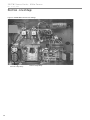
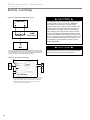
Figure 13: Test Mode Pins
Short test pins
together to enter
Test Mode and
speed-up timing
and delays for 20
minutes.
CXM Board
SYSTEM CHECKOUT
❑
System Water Temperature: Check load and
source water temperature for proper range and also
verify heating and cooling setpoints for
proper operation.
❑
System pH: System water pH is 7.5 - 8.5. Proper pH
promotes longevity of hoses and fittings.
❑
System Flushing: Water used in the system must
be potable quality initially and clean of dirt, piping
slag, and strong chemical cleaning agents. Verify
all air is purged from the system. Air in the system
can cause poor operation or system corrosion.
❑
Cooling Tower/Boiler: Check equipment for proper
setpoints and operation.
❑
Low Water Temperature Cutout: Verify low water
temperature cut-out controls are provided for the
outdoor portion of the loop or operating problems will
occur.
❑
Miscellaneous: Note any questionable aspects of
the installation.
35
50YEW Series Units - 60Hz Puron®
R e v. : 2 1 J u l y, 2 0 1 0
Unit Start-Up Procedure
WARNING!
WARNING! When the disconnect switch is closed,
high voltage is present in some areas of the electrical
panel. Exercise caution when working with energized
equipment.
1.
2.
3.
4.
Adjust all valves to their full open position. Turn on the
line power to all heat pump units.
Operate each heat pump in the heating cycle.
Verify heat exchanger flow rates based upon table 7 and
temperature drop/rise based upon unit performance
tables.
Establish a permanent operating record by logging the
unit operating conditions at initial start-up for each unit.
If a unit fails to operate, conduct the following checks:
a. Check the voltage and current. They should comply
with the electrical specifications described on the
unit nameplate.
WARNING!
WARNING! Verify ALL water controls are open and allow
water flow prior to engaging the compressor. Freezing of
the coax or water lines can permanently damage the heat
pump.
Table 8: Heat Exchanger Water Pressure Drop
Model
30°F
[-1°C]
50°F
[10°C]
70°F
[21°C]
0.60 [4.13]
0.85 [5.68]
0.48 [3.31]
0.73 [4.90]
0.37 [2.55]
0.60 [4.03]
Source/Outdoor Coax
010
6.6 [25.0]
8.3 [31.5]
Model
GPM
[l/m]
Pressure Drop psi [kPa]
70°F
[21°C]
90°F
[32°C]
110°F
[43°C]
130°F
[54°C]
0.58 [4.00]
0.97 [6.68]
0.55 [3.79]
0.82 [5.65]
0.53 [3.65]
0.70 [4.82]
1.77 [12.20]
3.54 [24.41]
1.75 [12.07]
3.49 [24.06]
Load/Indoor Heat Exchanger
010
5.4 [20.5]
7.3 [27.7]
0.62 [4.27]
1.13 [7.79]
DHW Heat Exchanger
010
3.5 [13.2]
5.4 [20.4]
1.80 [12.41]
3.61 [24.89]
Multiply psi by 2.31 to obtain feet of head
Multiply kPa by 10 to obtain mBar
36
Note: Units have a five minute time delay in the control
circuit that can be bypassed on the CXM PCB.
CXM Safety Control Reset
Lockout - In Lockout mode, the Status LED will begin fast
flashing. The compressor relay is turned off immediately.
Lockout mode can be soft reset via the “Y” input or can
be hard reset via the disconnect. The last fault causing the
lockout will be stored in memory and can be viewed by going
into test mode.
Fault Retry - In Fault Retry mode, the Status LED begins
slow flashing to signal that the control is trying to recover
from a fault input. The CXM control will stage off the outputs
and then “try again” to satisfy the thermostat "Y" input call.
Once the input calls are satisfied, the control will continue
on as if no fault occurred. If 3 consecutive faults occur
without satisfying the "Y" input call, then the control will
go to Lockout mode. The last fault causing the lockout will
be stored in memory and can be viewed by going into test
mode.
Consult the CXM AOM for complete descriptions.
Pressure Drop psi [kPa]
GPM
[l/m]
b. Look for wiring errors. Check for loose terminal
screws where wire connections have been made on
both the line and low-voltage terminal boards.
c. Check the supply and return piping. They must
be properly connected to the inlet and outlet
connections on the unit.
d. If the checks described above fail to reveal the
problem and the unit still will not operate, contact
a trained service technician to ensure proper
diagnosis and repair of the equipment.
50YEW Series Units - 60Hz Puron®
R e v. : 2 1 J u l y, 2 0 1 0
Preventive Maintenance
Water Coil Maintenance –
(Direct Ground Water Applications Only)
If the installation is performed in an area with a known high
mineral content (125 P.P.M. or greater) in the water, it is best
to establish with the owner a periodic maintenance schedule
so the coil can be checked regularly. Consult the well water
applications section of this manual for a more detailed water
coil material selection. Should periodic coil cleaning be
necessary, use standard coil cleaning procedures which are
compatible with either the heat exchanger material or copper
water lines. Generally, the more water flowing through the
unit the less chance for scaling.
Cabinet
Do not allow water to stay in contact with the cabinet for
long periods of time to prevent corrosion of the cabinet sheet
metal. Generally equipment cabinets are set up from the
floor a few inches for prevention. The cabinet can be cleaned
using a mild detergent.
Refrigerant System
To maintain sealed circuit integrity, do not install service
gauges unless unit operation appears abnormal. Reference
the operating chart for pressure and temperatures. Verify
that water flow rates are at proper levels before servicing the
refrigerant circuit.
Water Coil Maintenance –
(All Other Water Loop Applications)
Generally water coil maintenance is not needed however,
if the installation is located in a system with a known
high dirt or debris content, it is best to establish with the
owner a periodic maintenance schedule so the coil can be
checked regularly. These dirty installations are a result of the
deterioration of iron or galvanized piping or components in
the system or open cooling towers requiring heavy chemical
treatment and mineral buildup through water use. Should
periodic coil cleaning be necessary, use standard coil
cleaning procedures which are compatible with both the
heat exchanger material and copper water lines. Generally,
the more water flowing through the unit, the less chance for
scaling, however excessive flow rates can produce water (or
debris) velocities that can erode the heat exchanger wall and
ultimately produce leaks.
Compressor
Conduct annual amperage checks to ensure amp draw is
no more than 10% greater than that indicated by serial plate
data.
37
38
3OHDVHUHIHUWRWKH&DUULHU,QVWDOODWLRQ2SHUDWLRQDQG0DLQWHQDQFH0DQXDOIRURSHUDWLQJDQGPDLQWHQDQFHLQVWUXFWLRQV
5HY
3DUW1R&$
127(6RPHVWDWHVRU&DQDGLDQSURYLQFHVGRQRWDOORZOLPLWDWLRQVRQKRZORQJDQLPSOLHGZDUUDQW\ODVWVRUWKHOLPLWDWLRQRUH[FOXVLRQVRIFRQVHTXHQWLDORULQFLGHQWDOGDPDJHVVRWKHIRUHJRLQJH[FOXVLRQVDQGOLPLWDWLRQVPD\QRWDSSO\WR\RX7KLVZDUUDQW\JLYHV\RXVSHFLÀF
OHJDOULJKWVDQG\RXPD\DOVRKDYHRWKHUULJKWVZKLFKYDU\IURPVWDWHWRVWDWHDQGIURP&DQDGLDQSURYLQFHWR&DQDGLDQSURYLQFH
2%7$,1,1*:$55$17<3(5)250$1&(
1RUPDOO\WKHGHDOHURUVHUYLFHRUJDQL]DWLRQZKRLQVWDOOHGWKHSURGXFWVZLOOSURYLGHZDUUDQW\SHUIRUPDQFHIRUWKHRZQHU6KRXOGWKHLQVWDOOHUEHXQDYDLODEOHFRQWDFWDQ\&DUULHUUHFRJQL]HGGLVWULEXWRUGHDOHURUVHUYLFHRUJDQL]DWLRQ,IDVVLVWDQFHLVUHTXLUHGLQREWDLQLQJZDUUDQW\
SHUIRUPDQFHZULWHRUFDOO
&XVWRPHU6HUYLFH6:WK6WUHHW2NODKRPD&LW\2NODKRPD
/,0,7$7,212)/,$%,/,7<
&DUULHUVKDOOKDYHQROLDELOLW\IRUDQ\GDPDJHVLI&DUULHU·VSHUIRUPDQFHLVGHOD\HGIRUDQ\UHDVRQRULVSUHYHQWHGWRDQ\H[WHQWE\DQ\HYHQWVXFKDVEXWQRWOLPLWHGWRDQ\ZDUFLYLOXQUHVWJRYHUQPHQWUHVWULFWLRQVRUUHVWUDLQWVVWULNHVRUZRUNVWRSSDJHVÀUHÁRRGDFFLGHQW
VKRUWDJHVRIWUDQVSRUWDWLRQIXHOPDWHULDORUODERUDFWVRI*RGRUDQ\RWKHUUHDVRQEH\RQGWKHVROHFRQWURORI&DUULHU&$55,(5(;35(66/<',6&/$,06$1'(;&/8'(6$1</,$%,/,7<)25&216(48(17,$/25,1&,'(17$/'$0$*(,1&2175$&7)25
%5($&+2)$1<(;35(6625,03/,(':$55$17<25,17257:+(7+(5)25&$55,(5·61(*/,*(1&(25$6675,&7/,$%,/,7<
/,0,7$7,212)5(0(',(6
,QWKHHYHQWRIDEUHDFKRIWKH/LPLWHG([SUHVV:DUUDQW\&DUULHUZLOORQO\EHREOLJDWHGDW&DUULHU·VRSWLRQWRUHSDLUWKHIDLOHGSDUWRUXQLWRUWRIXUQLVKDQHZRUUHEXLOWSDUWRUXQLWLQH[FKDQJHIRUWKHSDUWRUXQLWZKLFKKDVIDLOHG,IDIWHUZULWWHQQRWLFHWR&DUULHU·VIDFWRU\LQ
2NODKRPD&LW\2NODKRPDRIHDFKGHIHFWPDOIXQFWLRQRURWKHUIDLOXUHDQGDUHDVRQDEOHQXPEHURIDWWHPSWVE\&DUULHUWRFRUUHFWWKHGHIHFWPDOIXQFWLRQRURWKHUIDLOXUHDQGWKHUHPHG\IDLOVRILWVHVVHQWLDOSXUSRVH&DUULHUVKDOOUHIXQGWKHSXUFKDVHSULFHSDLGWR&DUULHULQ
H[FKDQJHIRUWKHUHWXUQRIWKHVROGJRRGV6DLGUHIXQGVKDOOEHWKHPD[LPXPOLDELOLW\RI&DUULHU7+,65(0('<,67+(62/($1'(;&/86,9(5(0('<2)7+(%8<(525385&+$6(5$*$,167&$55,(5)25%5($&+2)&2175$&7)257+(
%5($&+2)$1<:$55$17<25)25&$55,(5·61(*/,*(1&(25,1675,&7/,$%,/,7<
/LPLWDWLRQ7KLV/LPLWHG([SUHVV:DUUDQW\LVJLYHQLQOLHXRIDOORWKHUZDUUDQWLHV,IQRWZLWKVWDQGLQJWKHGLVFODLPHUVFRQWDLQHGKHUHLQLWLVGHWHUPLQHGWKDWRWKHUZDUUDQWLHVH[LVWDQ\VXFKH[SUHVVZDUUDQW\LQFOXGLQJZLWKRXWOLPLWDWLRQDQ\H[SUHVVZDUUDQWLHVRUDQ\LPSOLHG
ZDUUDQWLHVRIÀWQHVVIRUSDUWLFXODUSXUSRVHDQGPHUFKDQWDELOLW\VKDOOEHOLPLWHGWRWKHGXUDWLRQRIWKH/LPLWHG([SUHVV:DUUDQW\
7KLV/LPLWHG([SUHVV:DUUDQW\DSSOLHVWR&DUULHUUHVLGHQWLDOJHRWKHUPDOSURGXFWVRUGHUHGIURP&DUULHURQRUDIWHU-XO\7KLVZRXOGJHQHUDOO\LQFOXGH&DUULHU*HRWKHUPDO8QLWVZLWKVHULDOQXPEHUVEHJLQQLQJZLWK´9µDQGODWHUDQGLVQRWUHWURDFWLYHWRDQ\SURGXFWV
RUGHUHGIURP&DUULHUSULRUWR-XO\WKLVZRXOGJHQHUDOO\LQFOXGH&DUULHU*HRWKHUPDO8QLWVZLWKVHULDOQXPEHUVEHJLQQLQJZLWK´9µDQGHDUOLHU,I\RXDUHXQVXUHLIWKLV/LPLWHG([SUHVV:DUUDQW\DSSOLHVWRWKHSURGXFW\RXKDYHSXUFKDVHGFRQWDFW&DUULHUDWWKHSKRQH
QXPEHURUDGGUHVVEHORZ
7KLV/LPLWHG([SUHVV:DUUDQW\SURYLGHVWKHOLPLWHGODERUDOORZDQFHFRYHUDJHVHWIRUWKDERYH2WKHUZLVH&DUULHULVQRWUHVSRQVLEOHIRU7KHFRVWVRIDQ\ÁXLGVUHIULJHUDQWRUV\VWHPFRPSRQHQWVVXSSOLHGE\RWKHUVRUDVVRFLDWHGODERUWRUHSDLURUUHSODFHWKHVDPHZKLFKLV
LQFXUUHGDVDUHVXOWRIDGHIHFWLYHSDUWFRYHUHGE\&DUULHU·V/LPLWHG([SUHVV:DUUDQW\7KHFRVWVRIODERUUHIULJHUDQWPDWHULDOVRUVHUYLFHLQFXUUHGLQGLDJQRVLVDQGUHPRYDORIWKHGHIHFWLYHSDUWRULQREWDLQLQJDQGUHSODFLQJWKHQHZRUUHSDLUHGSDUW7UDQVSRUWDWLRQFRVWVRI
WKHGHIHFWLYHSDUWIURPWKHLQVWDOODWLRQVLWHWR&DUULHURURIWKHUHWXUQRIWKDWSDUWLIQRWFRYHUHGE\&DUULHU·V/LPLWHG([SUHVV:DUUDQW\RU7KHFRVWVRIQRUPDOPDLQWHQDQFH
7KLVZDUUDQW\GRHVQRWFRYHUDQGGRHVQRWDSSO\WR$LUÀOWHUVIXVHVUHIULJHUDQWÁXLGVRLO3URGXFWVUHORFDWHGDIWHULQLWLDOLQVWDOODWLRQ$Q\SRUWLRQRUFRPSRQHQWRIDQ\V\VWHPWKDWLVQRWVXSSOLHGE\&DUULHUUHJDUGOHVVRIWKHFDXVHRIWKHIDLOXUHRIVXFKSRUWLRQ
RUFRPSRQHQW3URGXFWVRQZKLFKWKHXQLWLGHQWLÀFDWLRQWDJVRUODEHOVKDYHEHHQUHPRYHGRUGHIDFHG3URGXFWVRQZKLFKSD\PHQWWR&DUULHURUWRWKHRZQHU·VVHOOHURULQVWDOOLQJFRQWUDFWRULVLQGHIDXOW3URGXFWVVXEMHFWHGWRLPSURSHURULQDGHTXDWHLQVWDOODWLRQ
PDLQWHQDQFHUHSDLUZLULQJRUYROWDJHFRQGLWLRQV3URGXFWVVXEMHFWHGWRDFFLGHQWPLVXVHQHJOLJHQFHDEXVHÀUHÁRRGOLJKWQLQJXQDXWKRUL]HGDOWHUDWLRQPLVDSSOLFDWLRQFRQWDPLQDWHGRUFRUURVLYHDLURUOLTXLGVXSSO\RSHUDWLRQDWDEQRUPDODLURUOLTXLGWHPSHUDWXUHVRUÁRZ
UDWHVRURSHQLQJRIWKHUHIULJHUDQWFLUFXLWE\XQTXDOLÀHGSHUVRQQHO0ROGIXQJXVRUEDFWHULDGDPDJHV&RUURVLRQRUDEUDVLRQRIWKHSURGXFW3URGXFWVVXSSOLHGE\RWKHUV3URGXFWVZKLFKKDYHEHHQRSHUDWHGLQDPDQQHUFRQWUDU\WR&DUULHU·VSULQWHGLQVWUXFWLRQV
3URGXFWVZKLFKKDYHLQVXIÀFLHQWSHUIRUPDQFHDVDUHVXOWRILPSURSHUV\VWHPGHVLJQRULPSURSHUDSSOLFDWLRQLQVWDOODWLRQRUXVHRI&DUULHU·VSURGXFWVRU(OHFWULFLW\RUIXHOFRVWVRUDQ\LQFUHDVHVRUXQUHDOL]HGVDYLQJVLQVDPHIRUDQ\UHDVRQZKDWVRHYHU
7KLV/LPLWHG([SUHVV:DUUDQW\VKDOOFRYHUWKHODERULQFXUUHGE\&DUULHUDXWKRUL]HGVHUYLFHSHUVRQQHOLQFRQQHFWLRQZLWKWKHLQVWDOODWLRQRIDQHZRUUHSDLUHGZDUUDQW\SDUWWKDWLVFRYHUHGE\WKLV/LPLWHG([SUHVV:DUUDQW\RQO\WRWKHH[WHQWVSHFLÀFDOO\VHWIRUWKLQWKHWKHQH[LVWLQJ
ODERUDOORZDQFHVFKHGXOHSURYLGHGE\&DUULHU·V:DUUDQW\'HSDUWPHQWDQGRQO\DVIROORZV&DUULHU*HRWKHUPDO8QLWVIRUWZR\HDUVIURPWKH:DUUDQW\,QFHSWLRQ'DWH$X[LOLDU\HOHFWULFKHDWHUVDQGJHRWKHUPDOSXPSLQJPRGXOHVEXLOWRUVROGE\&DUULHUZKHQLQVWDOOHG
ZLWK&DUULHU*HRWKHUPDO8QLWVIRUWZR\HDUVIURPWKH:DUUDQW\,QFHSWLRQ'DWHDQG6HDOHGUHIULJHUDQWFLUFXLWFRPSRQHQWVRI&DUULHU*HRWKHUPDO8QLWVZKLFKFRPSRQHQWVRQO\LQFOXGHWKHFRPSUHVVRUUHIULJHUDQWWRDLUZDWHUKHDWH[FKDQJHUVUHYHUVLQJYDOYHERG\DQG
UHIULJHUDQWPHWHULQJGHYLFHIRUÀYH\HDUVIURPWKH:DUUDQW\,QFHSWLRQ'DWH$FWXDO/DERUFRVWVDUHQRWFRYHUHGE\WKLV/LPLWHG([SUHVV:DUUDQW\WRWKHH[WHQWWKH\H[FHHGWKHDPRXQWDOORZHGXQGHUVDLGDOORZDQFHVFKHGXOHWKH\DUHQRWVSHFLÀFDOO\SURYLGHGIRULQVDLG
DOORZDQFHVFKHGXOHWKH\DUHQRWWKHUHVXOWRIZRUNSHUIRUPHGE\&DUULHUDXWKRUL]HGVHUYLFHSHUVRQQHOWKH\DUHLQFXUUHGLQFRQQHFWLRQZLWKDSDUWQRWFRYHUHGE\WKLV/LPLWHG([SUHVV:DUUDQW\RUWKH\DUHLQFXUUHGPRUHWKDQWKHWLPHSHULRGVVHWIRUWKLQWKLVSDUDJUDSKDIWHUWKH
:DUUDQW\,QFHSWLRQ'DWH
7RPDNHDFODLPXQGHUWKLVZDUUDQW\SDUWVPXVWEHUHWXUQHGWR&DUULHULQ2NODKRPD&LW\2NODKRPDIUHLJKWSUHSDLGQRODWHUWKDQQLQHW\GD\VDIWHUWKHGDWHRIWKHIDLOXUHRIWKHSDUWLI&DUULHUGHWHUPLQHVWKHSDUWWREHGHIHFWLYHDQGZLWKLQ&DUULHU·V/LPLWHG([SUHVV:DUUDQW\
&DUULHUVKDOOZKHQVXFKSDUWKDVEHHQHLWKHUUHSODFHGRUUHSDLUHGUHWXUQVXFKWRDIDFWRU\UHFRJQL]HGGLVWULEXWRUGHDOHURUVHUYLFHRUJDQL]DWLRQ)2%&DUULHU2NODKRPD&LW\2NODKRPDIUHLJKWSUHSDLG7KHZDUUDQW\RQDQ\SDUWUHSDLUHGRUUHSODFHGXQGHUZDUUDQW\H[SLUHVDWWKH
HQGRIWKHRULJLQDOZDUUDQW\SHULRG
*5$172)/,0,7('(;35(66:$55$17<
&DUULHUZDUUDQWVLWVUHVLGHQWLDOJHRWKHUPDOSURGXFWVSXUFKDVHGDQGUHWDLQHGLQWKH8QLWHG6WDWHVRI$PHULFDDQG&DQDGDWREHIUHHIURPGHIHFWVLQPDWHULDODQGZRUNPDQVKLSXQGHUQRUPDOXVHDQGPDLQWHQDQFHDVIROORZV5HVLGHQWLDOJHRWKHUPDODLUFRQGLWLRQLQJKHDWLQJDQG
RUKHDWSXPSVZLWKPRGHOQXPEHUVEHJLQQLQJZLWK<WKDWDUHEXLOWRUVROGE\&DUULHU´&DUULHU*HRWKHUPDO8QLWVµIRUWHQ\HDUVIURPWKH:DUUDQW\,QFHSWLRQ'DWHDVGHÀQHGEHORZ$X[LOLDU\HOHFWULFKHDWHUVDQGJHRWKHUPDOSXPSLQJPRGXOHVEXLOWRUVROGE\&DUULHU
ZKHQLQVWDOOHGZLWK&DUULHU*HRWKHUPDO8QLWVIRUWHQ\HDUVIURPWKH:DUUDQW\,QFHSWLRQ'DWHDVGHÀQHGEHORZ6HDOHGUHIULJHUDQWFLUFXLWFRPSRQHQWVRI&DUULHU*HRWKHUPDO8QLWVZKLFKFRPSRQHQWVRQO\LQFOXGHWKHFRPSUHVVRUUHIULJHUDQWWRDLUZDWHUKHDWH[FKDQJHUV
UHYHUVLQJYDOYHERG\DQGUHIULJHUDQWPHWHULQJGHYLFHIRUWHQ\HDUVIURPWKH:DUUDQW\,QFHSWLRQ'DWHDVGHÀQHGEHORZDQG2WKHUDFFHVVRULHVDQGSDUWVEXLOWRUVROGE\&DUULHUZKHQLQVWDOOHGZLWK&DUULHU*HRWKHUPDO8QLWVIRURQH\HDUIURPWKHGDWHRIVKLSPHQW
IURP&DUULHU7KH´:DUUDQW\,QFHSWLRQ'DWHµVKDOOEHWKHGDWHRIRULJLQDOXQLWLQVWDOODWLRQRUVL[PRQWKVIURPGDWHRIXQLWVKLSPHQWIURP&DUULHUZKLFKHYHUFRPHVÀUVW
,WLVH[SUHVVO\XQGHUVWRRGWKDWXQOHVVDVWDWHPHQWLVVSHFLÀFDOO\LGHQWLÀHGDVDZDUUDQW\VWDWHPHQWVPDGHE\&DUULHU&RUSRUDWLRQD'HODZDUHFRUSRUDWLRQ´&DUULHUµRULWVUHSUHVHQWDWLYHVUHODWLQJWR&DUULHU·VSURGXFWVZKHWKHURUDOZULWWHQRUFRQWDLQHGLQDQ\VDOHVOLWHUDWXUH
FDWDORJRUDJUHHPHQWDUHQRWH[SUHVVZDUUDQWLHVDQGGRQRWIRUPDSDUWRIWKHEDVLVRIWKHEDUJDLQEXWDUHPHUHO\&DUULHU·VRSLQLRQRUFRPPHQGDWLRQRI&DUULHU·VSURGXFWV(;&(37$663(&,),&$//<6(7)257++(5(,17+(5(,612(;35(66:$55$17<
$672$1<2)&$55,(5·6352'8&76&$55,(50$.(612:$55$17<$*$,167/$7(17'()(&76&$55,(50$.(612:$55$17<2)0(5&+$17$%,/,7<2)7+(*22'6252)7+(),71(662)7+(*22'6)25$1<
3$57,&8/$5385326(
&$55,(5&25325$7,21
/,0,7('(;35(66:$55$17</,0,7$7,212)5(0(',(6$1'/,$%,/,7<)255(6,'(17,$/
*(27+(50$/352'8&76:,7+/$%25$//2:$1&(
50YEW Series Units - 60Hz Puron®
R e v. : 2 1 J u l y, 2 0 1 0
Warranty
50YEW Series Units - 60Hz Puron®
R e v. : 2 1 J u l y, 2 0 1 0
Notes:
39
50YEW Series Units - 60Hz Puron®
R e v. : 2 1 J u l y, 2 0 1 0
Revision History
Date
Page #
Description
21 July, 10
Wiring
Diagram Wire Diagram revision: water-side high pressure switches added
Pages
14 July, 10
Various
Compressor isolation upgrade from springs to grommets
1 July, 10
Various
Warranty, Nomenclature, Unit Photos Updated
30 March, 2010
6, 13
Dimensional Data and Electrical Data Updated
30 March, 2010
3
Decoder Updated
4 Jan., 2009
All
Updated DHW Option Information
15 Sept., 2009
27-31
2 June, 2009
All
13 May 2008
1, 32
31 Jan, 2008
17
Added Buffer Tank Interface Input Table
29 Nov, 2007
All
First Published
CXM/DXM Controls and CXM/DXM Safety Control Features Sections Added
R22 Information Removed
Part number corrected from 97B0064N01 to 97B0063N03
ISO 9001:2000
Certified
Quality: First & Always
7300 S.W. 44th Street
Oklahoma City, OK 73179
*97B0063N03*
Phone: 405-745-6000
Fax: 405-745-6058
97B0063N03
The Manufacturer works continually to improve its products. As a result, the design and specifications of each product at the time for order may
be changed without notice and may not be as described herein. Please contact the Manufacturer’s Customer Service Department at 1-405745-6000 for specific information on the current design and specifications. Statements and other information contained herein are not express
warranties and do not form the basis of any bargain between the parties, but are merely Manufacturer’s opinion or commendation of its products.
The management system governing the manufacture of Manufacturer’s products is ISO 9001:2000 certified.
© LSB, Inc. 2007
40
Rev.: 21 July, 2010