1
Bryant Geothermal Heat Pump Systems
Part II: Load Side Design / System Design & Selection
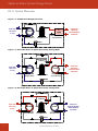
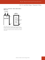
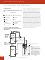
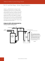
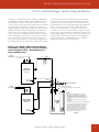
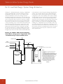
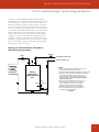
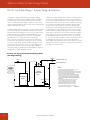
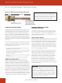
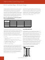
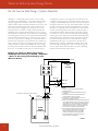
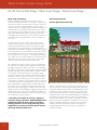
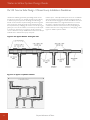
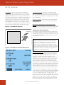
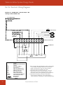
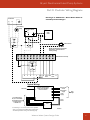
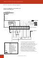
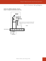
Drawing 2-7 – Alternate Buffer Tank (Electric Water Heater)
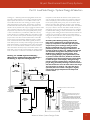
Typical Piping: A “true” buffer tank is the best approach for control
of a hydronic system using a heat pump. Tanks are usually well
insulated, and there are typically a number of water connections
(6 or more in many cases), so that plumbing is easier and water
flows are not restricted. However, due to the cost of buffer tanks,
some installers use an electric water heater for the buffer tank. An
electric water heater is much less expensive, but may not have
enough water connections, and may require external installation.
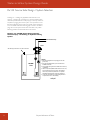
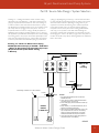
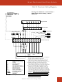
Drawing 2-7 may be used as an alternate piping schematic for
drawings 2-1 through 2-5 when an electric water heater is used.
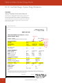
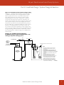
Drawing 2-6 requires a buffer tank due to the need for two aquastats. If a water heater is used, it must be approved as a heating
vessel (A.S.M.E. approval in the U.S.).
Drawing 2-7: Alternate Buffer Tank (Electric
Water Heater) Typical Piping
Notes 1,2
Note 1
From Water-to-Water Unit
To Water-to-Water Unit
H
C
Radiant
Floor
System
Electric
Water Heater
(ASME Approved)
Note 3
Note 3
Thermistor or Aqua-stat
NOTES:
1. Not all components shown (expansion tank, air vent, etc.).
Drawing is for buffer tank connections only.
2. Pump not needed for 50YEW unit with internal load pump option.
3. Thermistor or aqua-stat should be installed in an immersion
well. If water heater does not have well, one of the
heating elements should be removed, and a well adapter
should be installed. Locate thermistor/aqua-stat in the
bottom half of the tank.
4. Other components (additional ball valves, unions, etc.)
may be required for ease of service. This drawing
shows only minimum requirements. Your specific
installation will dictate final component selections.
5. Buffer tank must be approved as a heating vessel.
6. Local code supercedes any piping arrangements or
components shown on this drawing.
03Oct07
Water-to-Water System Design Guide
19