1
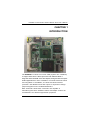
STX88831 Series Intel Atom™ N270 Processor STX Form Factor SoM User’s Manual Disclaimers This manual has been carefully checked and believed to contain accurate information. AXIOMTEK Co., Ltd. assumes no responsibility for any infringements of patents or any third party’s rights, and any liability arising from such use. AXIOMTEK does not warrant or assume any legal liability or responsibility for the accuracy, completeness or usefulness of any information in this document. AXIOMTEK does not make any commitment to update the information in this manual. AXIOMTEK reserves the right to change or revise this document and/or product at any time without notice. No part of this document may be reproduced, stored in a retrieval system, or transmitted, in any form or by any means, electronic, mechanical, photocopying, recording, or otherwise, without the prior written permission of AXIOMTEK Co., Ltd. CAUTION If you replace wrong batteries, it causes the danger of explosion. It is recommended by the manufacturer that you follow the manufacturer’s instructions to only replace the same or equivalent type of battery, and dispose of used ones. Copyright 2009 AXIOMTEK Co., Ltd. All Rights Reserved November 2009, Version A1 Printed in Taiwan ii ESD Precautions Computer boards have integrated circuits sensitive to static electricity. To prevent chipsets from electrostatic discharge damage, please take care of the following jobs with precautions: Do not remove boards or integrated circuits from their anti-static packaging until you are ready to install them. Before holding the board or integrated circuit, touch an unpainted portion of the system unit chassis for a few seconds. It discharges static electricity from your body. Wear a wrist-grounding strap, available from most electronic component stores, when handling boards and components. Trademarks Acknowledgments AXIOMTEK is a trademark of AXIOMTEK Co., Ltd. ® Windows is a trademark of Microsoft Corporation. AMI are trademarks of American Megatrend Inc. IBM, PC/AT, PS/2, VGA are trademarks of International Business Machines Corporation. ® Intel AtomTM are trademarks of Intel Corporation. Other brand names and trademarks are the properties and registered brands of their respective owners. iii Table of Contents Disclaimers ........................................................................................................... ii ESD Precautions ................................................................................................. iii CHAPTER 1 INTRODUCTION ..................................................................................... 1 1.1 Specifications ........................................................................................... 2 1.2 Utilities Supported .................................................................................... 4 CHAPTER 2 JUMPERS AND CONNECTORS............................................................ 5 2.1 Board Dimensions and Fixing Holes ....................................................... 5 2.2 Board Layout ........................................................................................... 7 2.3 Jumper Settings ...................................................................................... 9 2.4 Connectors............................................................................................ 11 CHAPTER 3 HARDWARE DESCRIPTION................................................................ 19 3.1 Microprocessors.................................................................................... 19 3.2 BIOS...................................................................................................... 19 3.3 System Memory .................................................................................... 19 3.4 I/O Port Address Map............................................................................ 20 3.5 Interrupt Controller ................................................................................ 22 3.6 Memory Map ......................................................................................... 23 CHAPTER 4 AMI BIOS UTILITY................................................................................ 26 4.1 Starting.................................................................................................. 26 4.2 Navigation Keys .................................................................................... 26 4.3 Main Menu ............................................................................................ 28 4.4 Advanced Menu .................................................................................... 29 4.5 PCI PnP Menu ...................................................................................... 44 4.6 Boot Menu............................................................................................. 47 4.7 Security Menu ....................................................................................... 50 4.8 Chipset Menu ........................................................................................ 51 4.9 Exit Menu .............................................................................................. 55 APPENDIX A WATCHDOG TIMER ........................................................................... 58 APPENDIX B DIGITAL I/O......................................................................................... 60 iv STX88831 STX Evaluation Platform Module Series User’s Manual CHAPTER 1 INTRODUCTION The STX88831 is a STX form factor SoM (System-On-a-Module) to support Intel® Atom™ N270 processor with FSB 533 MHz. It integrates Intel® 945GSE & ICH7M chipsets, designed with the spacelimited applications in mind. In addition of onboard features which are integrated on STX88831, the STX standard interface provides 4 PCI Masters and ISA output for expansion design purpose applied on the related Baseboard. With Axiomtek’s STX SoM, customers are capable of maintaining the same hardware kernel and adapt various I/O combinations for different application purposes. Introduction 1 STX88831 STX Evaluation Platform Module Series User’s Manual 1.1 Specifications CPU Intel® AtomTM N270 processor System Chipset Intel ® 945GSE & ICH7M CPU Frequency 533 MHz FSB BIOS AMI BIOS with Axiomtek standard features 8Mbit SPI Flash, DMI, Plug and Play “Load Optimized Default” to backup customized Setting in the BIOS flash chip to prevent from CMOS battery fail Ethernet Boot ROM (RPL & PXE), customized default saving features, used SPI type Flash memory System Memory One 200-pin unbuffered DDR2 SO-DIMM socket Maximum to 2GB DDR2 400/533 MHz memory L2 Cache Integrated in CPU IDE Interface One PATA-100 to two devices(IDE1 through STX interface connector) One SATA-150 connector Multi I/O Interface 2 One floppy port (STX interface connector)supporting up two devices One SPP/EPP/ECP parallel port(STX interface connector) Two RS-232 One PS2 Keyboard & Mouse support(STX interface connector) Introduction STX88831 STX Evaluation Platform Module Series User’s Manual USB Interface Four USB ports with fuse protection and complies with USB Spec. Rev. 2.0 Graphics Intel® 945GSE GMCH with GMA 950 integrated graphic engine CRT and TTL or LVDS LCD output Support 24-bit TTL TFT LCD via STX interface connector and 18/24-bit single/dual channel LVDS with Chrontel CH7308B from SDVO as EFP port through AXIOMTEK 30-pin FPC connector (FC1); please be noted that the LCD interface can be used either TTL TFT or LVDS at the same time Watchdog Timer 1~255 seconds; up to 255 levels Ethernet One Realtek RTL8103EL 10/100 Fast Ethernet via PCIExpres x1 Bus Audio AC-link through STX interface for codec on the baseboard Expansion Interface Four 32-bit/33MHz PCI Bus master Standard ISA Bus Power Management ACPI (Advanced Configuration and Power Interface) NOTE All specifications and images are subject to change without notice. Introduction 3 STX88831 STX Evaluation Platform Module Series User’s Manual 1.2 Utilities Supported Chipset Driver VGA Driver Ethernet Driver Audio Driver 4 Introduction STX88831 STX Evaluation Platform Module Series User’s Manual CHAPTER 2 JUMPERS AND CONNECTORS 2.1 Board Dimensions and Fixing Holes Component Side Jumpers and Connectors 5 STX88831 STX Evaluation Platform Module Series User’s Manual Solder Side 6 Jumpers and Connectors STX88831 STX Evaluation Platform Module Series User’s Manual 2.2 Board Layout Component Side Jumpers and Connectors 7 STX88831 STX Evaluation Platform Module Series User’s Manual Solder Side 8 Jumpers and Connectors STX88831 STX Evaluation Platform Module Series User’s Manual 2.3 Jumper Settings Proper jumer settings configure the STX88831 to meet your application purpose. We are herewith listing a summary table of all jumpers and default settings for onboard devices, respectively. Jumper Default Setting Jumper Setting JP1 LVDS Voltage Selection Default: 3.3V Short 1-2 JP2 Normal Operation/Clear CMOS setting Default: Normal Operation Short 1-2 SW1 Auto PowerButton Mode Selection Default:ATX Power Mode ON 2.3.1 LCD Voltage Selection Jumper (JP1) The board supports +3.3V or +5V flat panel displays. Configure the jumper JP1 to the appropriate voltage of the flat panel. Descriptio Function n LCD 3.3V Voltage (Default) Selection Jumper Setting 5V Jumpers and Connectors 9 STX88831 STX Evaluation Platform Module Series User’s Manual 2.3.2 CMOS Clear Jumper (JP2) You may need to use this jumper is to clear the CMOS memory if incorrect settings in the Setup Utility. Descriptio Function n CMOS Normal Clear (Default) Jumper Setting Clear CMOS 2.3.3 Auto Power Button Mode Selection Switch (SW1) When Jumper SW1 is set OFF for AC power input, the system will be automatically power ON without pressing soft power button; when SW1 is ON for AC power input, it is necessary to manually press soft power button to make the system power ON. Description Auto Power Button Mode Selection Function ATX Power Mode (Default) AT Power Mode Jumper Setting Note This function is similar to the feature of Power On after Power Failed, which is controlled by hardware circuitry instead of BIOS. 10 Jumpers and Connectors STX88831 STX Evaluation Platform Module Series User’s Manual 2.4 Connectors The connectors allow the CPU Board to connect with other parts of the system. Some problems encountered by your system may be a result from loose or improper connections. Ensure that all connectors are in place and firmly attached. The following table lists the function of each connector on the STX88831. Connectors Label DDRII SODIMM Connector DIMM1 LVDS Connector FC1 SATA Connector SATA1 STX Connector – P1 SP1 STX Connector – P2 SP2 Jumpers and Connectors 11 STX88831 STX Evaluation Platform Module Series User’s Manual 2.4.1 LVDS Flat Panel Connector (FC1) The board has a 30-pin connector FC1 for LVDS Interface LCD. It is strongly recommended to use the matching Hirose DF19G-30P-1H 30pin connector for LVDS on the board. Pin 12 Signal Pin Signal 1 VCCM 2 VCCM 3 VCCM 4 L_VDDEN 5 GFPDE 6 LA_BLKEN 7 GND 8 Channel B D3+ (24-Bit support) 9 Channel B D3- (24-Bit support) 10 Channel B CLK+ 11 Channel B CLK- 12 Channel B D2+ 13 Channel B D2- 14 GND 15 Channel B D1+ 16 Channel B D1- 17 GND 18 Channel B D0+ 19 Channel B D0- 20 Channel A D3+ (24-Bit support) 21 Channel A D3- (24-Bit support) 22 Channel A CLK+ 23 Channel A CLK- 24 GND 25 Channel A D2+ 26 Channel A D2- 27 Channel A D1+ 28 Channel A D1- 29 Channel A D0+ 30 Channel A D0- Jumpers and Connectors STX88831 STX Evaluation Platform Module Series User’s Manual 2.4.2 Serial ATA Connector (SATA1) The SATA connector SATA1 is for high-speed SATA interface ports, and It can be connected to hard disk devices. Pin Signal 1 GND 2 SATA_TX+ 3 SATA_TX- 4 GND 5 SATA_RX- 6 SATA_RX+ 7 GND 2.4.3 STX Connector (SP1, SP2) Jumpers and Connectors 13 STX88831 STX Evaluation Platform Module Series User’s Manual SP1 SP2 Pin Description Pin Description Pin Description Pin Description 1 GND 2 NET_TXD+ 1 IDE_RESET# 2 GND 4 NET_TXD- 3 IDE_D7 4 ISA_ IOCHCK# 6 NET_CTREF 5 IDE_D8 6 ISA_SD7 3 5 NET_ACT_LE D# NET_LINK_LE D# 7 DISK_LED# 8 LAN_RXD+ 7 IDE_D6 8 ISA_ RSETDRV 9 SPEAKR 10 LAN_RXD- 9 IDE_D9 10 ISA_SD6 11 PCI_GNT3# 12 GND 11 IDE_D5 12 VCC_5V 13 RSTBTN# 14 VCC_5V_SBY 13 IDE_D10 14 ISA_SD5 15 PWRBTN# 16 VCC_5V_SBY 15 IDE_D4 16 ISA_IRQ9 17 WAKE_EVENT 18 PS_ON# 17 IDE_D11 18 ISA_SD4 19 GND 20 AC_RST# 19 IDE_D3 20 GND 21 PS2_KB_CLK 22 AC_SDIN 21 IDE_D12 22 ISA_SD3 23 PS2_KB_DAT A 24 AC_BITCLK 23 IDE_D2 24 ISA_DRQ2 25 PS2_MS_CLK 26 AC_SDOUT 25 IDE_D13 26 ISA_SD2 27 PS2_MS_DAT A 28 AC_SYNC 27 IDE_D1 28 VCC_5V 29 VCC_5V 30 GND 29 IDE_D14 30 ISA_SD1 31 N.C 32 I2C_CLK 31 IDE_D0 32 ISA_ZEROWS # 33 PCI_REQ3# 34 I2C_DATA 33 IDE_D15 34 ISA_SD0 36 GND 35 IDE_IRQ 36 IDE_PATADET 37 IDE_REQ 38 ISA_ GPCS# 39 IDE_IOW# 40 N.C CPU_THERM D_A CPU_THERM D_C 35 37 39 VCC_RTC 14 38 40 IR_RX (OPTION) IR_TX (OPTION) Jumpers and Connectors STX88831 STX Evaluation Platform Module Series User’s Manual SP1 SP2 Pin Description Pin Description Pin Description Pin Description 41 VCC_5V 42 HW_VCORE 41 IDE_IOR# 42 ISA_ IOCHRDY 43 PCI_AD0 44 VCC_5V 43 IDE_IORDY 44 GND 45 PCI_AD1 46 VCC_5V 45 IDE_ACK# 46 ISA_ MEMCS16# 47 VCC_5V 48 PCI_AD2 47 IDE_A1 48 ISA_ SBHE# 49 PCI_AD4 50 PCI_AD5 49 IDE_A0 50 ISA_AEN 51 PCI_AD3 52 GND 51 IDE_A2 52 ISA_SMEMW# 53 GND 54 PCI_C/BE0# 53 IDE_CS0# 54 ISA_IOCS16# 55 PCI_AD6 56 PCI_AD7 55 IDE_CS1# 56 ISA_LA23 57 PCI_AD8 58 GND 57 GND 58 ISA_SA19 59 GND 60 PCI_AD9 59 FDC_DENSEL 60 ISA_SMEMR# 61 PCI_AD10 62 PCI_AD11 61 FDC_INDEX# 62 ISA_IRQ10 63 VCC_3.3V 64 VCC_3.3V 63 FDC_MTR0# 64 ISA_LA22 65 N.C 66 PCI_AD14 65 N.C 66 ISA_SA18 67 PCI_AD12 68 PCI_AD13 67 FDC_DS0# 68 ISA_IOW# 69 PCI_AD15 70 VCC_3.3V 69 N.C 70 ISA_IRQ11 71 VCC_3.3V 72 PCI_C/BE1# 71 FDC_DIR# 72 ISA_LA21 73 VCC_3.3V 74 PCI_SERR# 73 FDC_STEP# 74 ISA_SA17 76 ISA_IOR# 75 PCI_PAR 76 GND 75 FDC_ WDATA# 77 GND 78 GND 77 FDC_WGATE# 78 ISA_IRQ12 79 GND 80 PCI_PERR# 79 FDC_TRACK0 # 80 ISA_LA20 Jumpers and Connectors 15 STX88831 STX Evaluation Platform Module Series User’s Manual SP1 SP2 Pin Description Pin Description Pin Description Pin Description 81 PCI_LOCK# 82 PCI_STOP# 81 FDC_WP# 82 ISA_SA16 83 VCC_3.3V 84 VCC_3.3V 83 FDC_RDATA# 84 ISA_DACK3# 85 VCC_3.3V 86 VCC_3.3V 85 FDC_HDSEL# 86 ISA_IRQ15 88 ISA_LA19 87 PCI_DEVSEL# 88 PCI_TRDY# 87 FDC_DSKCHG # 89 PCI_IRDY# 90 PCI_FRAME# 89 GND 90 ISA_SA15 91 GND 92 GND 91 LPT_STB# 92 ISA_DRQ3 93 GND 94 GND 93 LPT_AFD# 94 ISA_IRQ14 95 PCI_C/BE2# 96 PCI_AD16 95 LPT_PD0 96 ISA_LA18 97 PCI_AD17 98 PCI_AD18 97 LPT_ERROR# 98 ISA_SA14 99 VCC_3.3V 100 VCC_3.3V 99 LPT_PD1 100 ISA_DACK1# 101 VCC_3.3V 102 PCI_AD21 101 LPT_INIT# 102 ISA_LA17 103 PCI_AD19 104 PCI_AD20 103 LPT_PD2 104 ISA_DACK0# 105 PCI_AD22 106 VCC_3.3V 105 LPT_SLIN# 106 ISA_DRQ1 107 USB2- 108 PCI_AD23 107 LPT_PD3 108 ISA_SA13 109 USB2+ 110 PCI_PME# 109 LPT_PD4 110 ISA_ MEMR# 111 USB3+ 112 GND 111 LPT_PD5 112 ISA_DRQ0 113 USB3- 114 PCI_AD24 113 LPT_PD6 114 ISA_ REFRESH# 115 PCI_CLK3 116 PCI_C/BE3# 115 LPT_PD7 116 ISA_SA12 117 PCI_AD25 118 GND 117 LPT_ACK# 118 ISA_ MEMW# 119 GND 120 PCI_AD26 119 LPT_BUSY 120 ISA_DACK5# 16 Jumpers and Connectors STX88831 STX Evaluation Platform Module Series User’s Manual SP1 SP2 Pin Description Pin Description Pin Description Pin Description 121 PCI_AD28 122 PCI_AD29 121 LPT_PE 122 ISA_SYSCLK 123 PCI_AD27 124 VCC_3.3V 123 LPT_SLCT 124 ISA_SA11 125 VCC_3.3V 126 VCC_3.3V 125 GND 126 ISA_SD8 127 PCI_AD31 128 PCI_REQ1# 127 DCD1# 128 ISA_DRQ5 129 PCI_AD30 130 PCI_REQ0# 129 RXD1 130 ISA_IRQ7 131 VCC_5V 132 VCC_5V 131 TXD1# 132 ISA_SA10 133 VCC_5V 134 VCC_5V 133 DTR1# 134 ISA_SD9 135 PCI_GNT0# 136 PCI_GNT2# 135 DSR1# 136 ISA_DACK6# 137 PCI_REQ2# 138 PCI_GNT1# 137 RTS1# 138 ISA_IRQ6 139 GND 140 GND 139 CTS1# 140 ISA_SA9 141 PCI_CLK1 142 GND 141 RI1# 142 ISA_SD10 143 GND 144 PCI_CLK2 143 DCD2# 144 ISA_DRQ6 145 PCI_CLK0 146 VCC_5V 145 RXD2 146 ISA_IRQ5 147 VCC_5V 148 N.C 147 TXD2# 148 ISA_SA8 149 FP_SCLK 150 FP_SDATA 149 DTR2# 150 ISA_SD11 151 PCI_RESET# 152 PCI_INTD# 151 DSR2# 152 ISA_DACK7# 153 PCI_INTC# 154 PCI_INTA# 153 RTS2# 154 ISA_IRQ4 155 PCI_INTB# 156 FP_BKL_EN 155 CTS2# 156 ISA_SA7 157 GND 158 FP_EDGE 157 RI2# 158 ISA_SD12 159 FP_ VSYNC 160 FP_ HSYNC 159 GND 160 ISA_DRQ7 Jumpers and Connectors 17 STX88831 STX Evaluation Platform Module Series User’s Manual SP1 SP2 Pin Description Pin Description Pin Description Pin Description 161 FP_DSEL 162 GND 161 USB0- 162 ISA_IRQ3 163 FP_VDD_EN 164 FP_CLK_P 163 USB0+ 164 ISA_SA6 165 FP_BSEL 166 GND 165 GND 166 ISA_SD13 167 FP_DATA_EN ABLE 168 FP_CLK_S 167 USB1- 168 VCC_5V 169 VCC_5V 170 VCC_5V 169 USB1+ 170 ISA_DACK2# 171 FP_D0 172 FP_D12 171 GND 172 ISA_SA5 174 ISA_SD14 176 ISA_ MASTER# 178 ISA_TC 180 ISA_SA4 USB_0_1_OC # USB_2_3_OC # VGA_DCC_CL K VGA_DCC_DA TA 173 FP_D1 174 FP_D13 173 175 FP_D2 176 GND 175 177 FP_D3 178 FP_D14 177 179 GND 180 FP_D15 179 181 FP_D4 182 FP_D16 181 GND 182 ISA_SD15 183 FP_D5 184 FP_D17 183 VGA_GREEN 184 WOL 185 FP_D6 186 GND 185 GND 186 ISA_BALE 187 FP_D7 188 FP_D18 187 VGA_RED 188 ISA_SA3 189 GND 190 FP_D19 189 GND 190 VCC_5V 191 FP_D8 192 FP_D20 191 VGA_BLUE 192 ISA_SA2 193 FP_D9 194 FP_D21 193 GND 194 ISA_OSC 195 FP_D10 196 GND 195 VGA_VSYNC 196 ISA_SA1 197 FP_D11 198 FP_D22 197 GND 198 ISA_SA0 199 GND 200 FP_D23 199 VGA_HSYNC 200 GND -- End of STX Connector Table -- 18 Jumpers and Connectors STX88831 STX Evaluation Platform Module Series User’s Manual CHAPTER 3 HARDWARE DESCRIPTION 3.1 Microprocessors ® The STX88831 Series supports Intel Atom™ N270 processor, which make your system operated under Windows XP/Vista and Linux environments. The system performance depends on the microprocessor. Make sure your installed microprocessor with all correct settings that prevent the CPU from damages. 3.2 BIOS The STX88831 Series uses American Megatrends BIOS with 8Mbit SPI Flash, DMI, Plug and Play. 3.3 System Memory The STX88831 Series industrial CPU card supports one 200-pin unbuffered DDR2 SO-DIMM socket for a maximum memory of 2GB DDR2 SDRAM. The memory module can come in sizes of 128MB, 256MB, 512MB, 1GB and 2GB. Hardware Description 19 STX88831 STX Evaluation Platform Module Series User’s Manual 3.4 I/O Port Address Map There are total 1KB port addresses (under OS WinXP) available for assignment to other devices via I/O expansion cards. Address 0000-000F 0081-0083 0087 0089-008B 008F 00C0-00DF Direct Memory Access controller 0000-0CF7 0D00-FFFF PCI Bus 0020-0021 00A0-00A1 Interrupt controller 0040-0043 System timer 0060 0064 Standard 101/102 Key or Microsoft Natural PS/2 Keyboard 0061 System speaker 0070-0071 System CMOS/Real time clock 0274-0277 0279 0A79 ISAPNP Read Data Port 02F8-02FF Communications Port (COM2) 0378-037F Printer Port (LPT1) 03B0-03BB 03C0-03DF DC80-DC87 Mobile Intel® 945 Express Chipset Family 03F8-03FF Communications Port (COM1) 0400-041F Intel® 82801G (ICH7 Family) SMBus Controller DC00-DC1F 20 Devices Intel® 82801G (ICH7 Family) USB Universal Host Controller Hardware Description STX88831 STX Evaluation Platform Module Series User’s Manual Address Devices CC00-CC0F CC80-CC83 D000-D007 D080-D083 D400-D407 Intel® 82801GBM/GHM (ICH7-M Family) Serial ATA Storage Controller D480-D4BF D800-D8FF Vinyl AC’97 codec Combo Driver (WDM) E000-EFFF Intel® 82801G (ICH7 Family) PCI Express Root Port EC00-ECFF Realtek PCIe FE Family Controller FFA0-FFAF Intel® 82801G (ICH7 Family) Ultra ATA Storage Controllers Hardware Description 21 STX88831 STX Evaluation Platform Module Series User’s Manual 3.5 Interrupt Controller The STX88831 Series is a 100% PC compatible control board. It consists of 16 interrupt request lines, and four out of them can be programmable. The mapping list of the 16 interrupt request lines is shown as the following table. IRQ 22 Parity check error IRQ0 System timer output IRQ1 Standard 101/102 Key or Microsoft Natural PS/2 Keyboard IRQ3 Communication Port (COM2) IRQ4 Communication Port (COM1) IRQ8 System CMOS/Real time clock IRQ9 Microsoft ACPI Controller IRQ11 Intel® 82801G (ICH7 Family) SMBus Controller IRQ12 Microsoft PS/2 Mouse IRQ13 Numeric data processor IRQ14 Primary IDE Channel IRQ16 Intel® 82801G (ICH7 Family) PCI Express Root Port IRQ16 Mobile Intel® 945 Express Chipset Family IRQ16 Realtek PCIe FE Family Controller IRQ17 Vinyl AC’97 codec Combo Driver (WDM) IRQ19 Intel® 82801GBM/GHM (ICH7-M Family) Serial ATA Storage Controller IRQ23 Intel® 82801G (ICH7 Family) USB Universal Host Controller IRQ23 Intel® 82801G (ICH7 Family) USB2 Enhanced Host Controller Hardware Description STX88831 STX Evaluation Platform Module Series User’s Manual 3.6 Memory Map Address Devices 000000000009FFFF System board 000A0000000BFFFF Mobile Intel® 945 Express Chipset Family 000A0000000BFFFF PCI Bus 000C0000000CFFFF System board 000D0000000DFFFF PCI Bus 000E0000000FFFFF System board 001000001F7FFFFF System board 1F800000 DFFFFFFF PCI Bus D0000000DFFFFFFF Mobile Intel® 945 Express Chipset Family E4000000 – FED8FFFF PCI Bus FDF00000FDFFFFFF Intel® 82801G (ICH7 Family) PCI Express Root Port FDFF0000FDFFFFFF Realtek PCIe FE Family Controller FE980000FE9FFFFF Mobile Intel® 945 Express Chipset Family FEA3B000FEA3B3FF Intel® 82801GBM/GHM (ICH7-M Family) Serial ATA Storage Controller FEA3B400FEA3B4FF Vinyl AC’97 codec Combo Driver (WDM) FEA3B800FEA3B9FF Vinyl AC’97 codec Combo Driver (WDM) FEA3BC00FEA3BFFF Intel® 82801G (ICH7 Family) USB2 Enhanced Host Controller Hardware Description 23 STX88831 STX Evaluation Platform Module Series User’s Manual Address 24 Devices FEA40000FEA7FFFF Mobile Intel® 945 Express Chipset Family FEA80000FEAFFFFF Mobile Intel® 945 Express Chipset Family FEB00000FEAFFFFF Intel® 82801G (ICH7 Family) PCI Express Root Port FEBFF000FEBFFFFF Realtek PCIe FE Family Controller Hardware Description STX88831 STX Evaluation Platform Module Series User’s Manual MEMO Hardware Description 25 STX88831 STX Evaluation Platform Module Series User’s Manual CHAPTER 4 AMI BIOS UTILITY This chapter provides users with detailed description how to set up basic system configuration through the AMIBIOS8 BIOS setup utility. 4.1 Starting To enter the setup screens, follow the steps below: 1. 2. Turn on the computer and press the <Del> key immediately. After you press the <Delete> key, the main BIOS setup menu displays. You can access the other setup screens from the main BIOS setup menu, such as the Chipset and Power menus. 4.2 Navigation Keys The BIOS setup/utility uses a key-based navigation system called hot keys. Most of the BIOS setup utility hot keys can be used at any time during the setup navigation process. These keys include <F1>, <F10>, <Enter>, <ESC>, <Arrow> keys, and so on. Note Some of navigation keys differ from one screen to another. 26 AMI BIOS Utility STX88831 STX Evaluation Platform Module Series User’s Manual Left/Right The Left <Arrow> keys allow you to select a setup screen. Up/Down The Up and Down <Arrow> keys allow you to select a setup screen or sub-screen. + Plus/Minus The Plus and Minus <Arrow> keys allow you to change the field value of a particular setup item. Tab The <Tab> key allows you to select setup fields. F1 The <F1> key allows you to display the General Help screen. F10 The <F10> key allows you to save any changes you have made and exit Setup. Press the <F10> key to save your changes. Esc The <Esc> key allows you to discard any changes you have made and exit the Setup. Press the <Esc> key to exit the setup without saving your changes. Enter AMI BIOS Utility The <Enter> key allows you to display or change the setup option listed for a particular setup item. The <Enter> key can also allow you to display the setup sub- screens. 27 STX88831 STX Evaluation Platform Module Series User’s Manual 4.3 Main Menu When you first enter the Setup Utility, you will enter the Main setup screen. You can always return to the Main setup screen by selecting the Main tab. There are two Main Setup options. They are described in this section. The Main BIOS Setup screen is shown below. System Time/Date Use this option to change the system time and date. Highlight System Time or System Date using the <Arrow> keys. Enter new values through the keyboard. Press the <Tab> key or the <Arrow> keys to move between fields. The date must be entered in MM/DD/YY format. The time is entered in HH:MM:SS format. 28 AMI BIOS Utility STX88831 STX Evaluation Platform Module Series User’s Manual 4.4 Advanced Menu The Advanced menu allows users to set configuration of the CPU and other system devices. You can select any of the items in the left frame of the screen to go to the sub menus: CPU Configuration IDE Configuration Floppy Configuration SuperIO Configuration Hardware Health CPU Configuration ACPI Configuration APM Configuration MPS Configuration PCI Express Configuration USB Configuration For items marked with “”, please press <Enter> for more options. AMI BIOS Utility 29 STX88831 STX Evaluation Platform Module Series User’s Manual CPU Configuration This screen shows the CPU Configuration, and you can change the value of the selected option. 30 Execute-Disable Bit Capability This item helps you enable or disable the No-Execution Page Protection Technology. Hyper Threading Technology Use this item to enable or disable Hyper-Threading Technology, which makes a single physical processor perform multi-tasking function as two logical ones. Intel (R) SpeedStep (tm) tech This item helps you enable or disable the Intel SpeedStep Technology. AMI BIOS Utility STX88831 STX Evaluation Platform Module Series User’s Manual Intel (R) C-STATE tech Use this item to enable or disable the C-State technology. Enhanced C-States This item allows you to enable or disable any available enhanced C-states ( C1E, C2E, C3E, C4E and Hard C4E). IDE Configuration You can use this screen to select options for the IDE Configuration, and change the value of the selected option. A description of the selected item appears on the right side of the screen. For items marked with “”, please press <Enter> for more options. ATA/IDE Configuration Use this item to specify the integrated IDE controller. There are three options for your selection: Disabled and Compatible. AMI BIOS Utility 31 STX88831 STX Evaluation Platform Module Series User’s Manual Legacy IDE Channels When the ATA/IDE Configuration is set to Compatible, this item will be displayed. Primary/Secondary IDE Master/Slave Select one of the hard disk drives to configure IDE devices installed in the system by pressing <Enter> for more options. Floppy Configuration You can use this screen to select options for the Floppy Configuration, and change the value of the selected option. A description of the selected item appears on the right side of the screen. For items marked with “”, please press <Enter> for more options. 32 AMI BIOS Utility STX88831 STX Evaluation Platform Module Series User’s Manual SuperIO Configuration You can use this screen to select options for the SuperIO Configuration, and change the value of the selected option. A description of the selected item appears on the right side of the screen. OnBoard Floppy Controller Use this item to enable or disable the onboard floppy drive controller. Serial Port1 Address This item specifies the base I/O port address and Interrupt Request address of serial port 1. The Optimal setting is 3F8/IRQ4. The Fail-Safe default setting is Disabled. Serial Port1 IRQ This item specifies the IRQ used by the serial port 1. AMI BIOS Utility 33 STX88831 STX Evaluation Platform Module Series User’s Manual Serial Port2 Address This item specifies the base I/O port address and Interrupt Request address of serial port 2. The Optimal setting is 2F8/IRQ3. The Fail-Safe setting is Disabled. Serial Port2 IRQ This item specifies the IRQ used by the serial port 2. Parallel Port Address This item allows you to determine the I/O address for onboard parallel port. There are several options for your selection. Parallel Port Mode Select an operating mode for the onboard parallel (printer) port. Parallel Port IRQ Use this item to set up the IRQ for onboard parallel port. 34 AMI BIOS Utility STX88831 STX Evaluation Platform Module Series User’s Manual Hardware Health Configuration This screen shows the Hardware Health CPU Configuration, and a description of the selected item appears on the right side of the screen. System Temperature/CPU Temperature These items display the temperature of CPU and System, Vcore, etc AMI BIOS Utility 35 STX88831 STX Evaluation Platform Module Series User’s Manual ACPI Configuration You can use this screen to select options for the ACPI Configuration, and change the value of the selected option. A description of the selected item appears on the right side of the screen. 36 AMI BIOS Utility STX88831 STX Evaluation Platform Module Series User’s Manual General ACPI Configuration Scroll to this item and press <Enter> to view the General ACPI Configuration sub menu, which contains General ACPI (Advanced Configuration and Power Management Interface) options for your configuration. AMI BIOS Utility 37 STX88831 STX Evaluation Platform Module Series User’s Manual 38 Advanced ACPI Configuration Scroll to this item and press <Enter> to view the Advanced ACPI Configuration sub menu, which contains Advanced ACPI (Advanced Configuration and Power Management Interface) options for your configuration. AMI BIOS Utility STX88831 STX Evaluation Platform Module Series User’s Manual APM Configuration You can use this screen to select options for the APM Configuration, and change the value of the selected option. A description of the selected item appears on the right side of the screen. Power Management/APM Set this item to allow Power Management/APM support. The default setting is Enabled. Disabled Enabled AMI BIOS Utility Set this item to prevent the chipset power management and APM (Advanced Power Management) features. Set this item to allow the chipset power management and APM (Advanced Power Management) features. This is the default setting. 39 STX88831 STX Evaluation Platform Module Series User’s Manual Video Power Down Mode This option specifies the Power State that the video subsystem enters when the BIOS places it in a power saving state after the specified period of display inactivity has expired. The default setting is Suspend. Disabled Standby Suspend 40 This setting prevents the BIOS from initiating any power saving modes concerned with the video display or monitor. This option places the monitor into standby mode after the specified period of display inactivity has expired. This means the monitor is not off. The screen will appear blacked out. The standards do not cite specific power ratings because they vary from monitor to monitor. This option places the monitor into suspend mode after the specified period of display inactivity has expired. This means the monitor is not off. The screen will appear blacked out. The standards do not cite specific power ratings because they vary from monitor to monitor, but this setting use less power than Standby mode. This is the default setting. Hard Disk Drive Power Down Mode This option specifies the power conserving state that the hard disk drive enters after the specified period of hard drive inactivity has expired. The default setting is Suspend. Disabled This setting prevents hard disk drive power down mode. Standby This option stops the hard disk drives from spinning during a system standby. Suspend This option cuts the power to the hard disk drives during a system suspend. This is the default setting. Suspend Time Out (Minute) This option specifies the length of time the system waits before it enters suspend mode. The default setting is Disabled. AMI BIOS Utility STX88831 STX Evaluation Platform Module Series User’s Manual Disabled 1 Min 4 Min 10 Min This setting prevents the system from entering suspend mode. This is the default setting. Set this item to allow the computer system to enter suspend mode after being inactive for 1 minute. Set this item to allow the computer system to enter suspend mode after being inactive for 4 minutes. Set this item to allow the computer system to enter suspend mode after being inactive for 10 minutes. Throttle Slow Clock Ratio Use this item to specify the speed of the system clock when running the power saving states. Power Button Mode This option specifies how the externally mounted power button on the front of the computer chassis is used. The default setting is On/Off. On/Off Pushing the power button turns the computer on or off. This is the default setting. This is the default setting. Suspend Pushing the power button places the computer in Suspend mode or Full On power mode. ***** Advanced Resume Event Controls ***** Resume On RTC Alarm You can set “Resume On RTC Alarm” item to enabled and key in Data/time to power on system. AMI BIOS Utility 41 STX88831 STX Evaluation Platform Module Series User’s Manual MPS Configuration This screen shows the MPS (Multi Processor Specification) Configuration, and you can change its value. A description of the selected item appears on the right side of the screen. 42 MPS Revision Use this item to select MPS (Multi Processor Specification) Revision 1.1 or 1.4. AMI BIOS Utility STX88831 STX Evaluation Platform Module Series User’s Manual USB Configuration You can use this screen to select options for the USB Configuration, and change the value of the selected option. A description of the selected item appears on the right side of the screen. USB 2.0 Controller Mode Use this item to configure the USB 2.0 controller. The default setting is HiSpeed. Legacy USB Support Use this item to enable or disable support for USB device on legacy operating system. The default setting is Enabled. BIOS EHCI Hand-Off Enabling this item provide the support for operating systems without an EHCI hand-off feature. The default setting is Enabled. AMI BIOS Utility 43 STX88831 STX Evaluation Platform Module Series User’s Manual 4.5 PCI PnP Menu The PCI PnP menu allows users to change the advanced settings for PCI/PnP devices. (1) 44 AMI BIOS Utility STX88831 STX Evaluation Platform Module Series User’s Manual (2) Clear NVRAM Use this item to clear the data in the NVRAM (CMOS). Here are the options for your selection, No and Yes. Plug & Play O/S When the setting is No, Use this item to configure all the devices in the system. When the setting is Yes and if you install a Plug and Play operating system, the operating system configures the Plug and Play devices not required for boot. The default setting is No. PCI Latency Timer This item controls how long a PCI device can hold the PCI bus before another takes over. The longer the latency, the longer the PCI device can retain control of the bus before handing it over to another PCI device. There are several options for your selection. Allocate IRQ to PCI VGA This item allows BIOS to choose an IRQ to assign for the PCI VGA card. Here are the options for your selection, No and Yes. AMI BIOS Utility 45 STX88831 STX Evaluation Platform Module Series User’s Manual 46 Palette Snooping Some old graphic controllers need to “snoop” on the VGA palette, and then map it to their display as a way to provide boot information and VGA compatibility. This item allows such snooping to take place. Here are the options for your selection, Disabled and Enabled. PCI IDE BusMaster This item is a toggle for the built-in driver that allows the onboard IDE controller to perform DMA (Direct Memory Access) transfer. Here are the options for your selection, Disabled and Enabled. OffBoard PCI/ISA IDE Card This item is for any other non-onboard PCI/ISA IDE controller adapter. There are several options for your selection. IRQ3/4/5/7/9/10/11/14/15 These items will allow you to assign each system interrupt a type, depending on the type of device using the interrupt. The option “Available” means the IRQ is going to assign automatically. Here are the options for your selection, Available and Reserved. DMA Channel 0/1/3/5/6/7 These items will allow you to assign each DMA channel a type, depending on the type of device using the channel. The option “Available” means the channel is going to assign automatically. Here are the options for your selection, Available and Reserved. AMI BIOS Utility STX88831 STX Evaluation Platform Module Series User’s Manual 4.6 Boot Menu The Boot menu allows users to change boot options of the system. You can select any of the items in the left frame of the screen to go to the sub menus: Boot Settings Configuration LAN Boot Option For items marked with “”, please press <Enter> for more options. AMI BIOS Utility 47 STX88831 STX Evaluation Platform Module Series User’s Manual Boot Settings Configuration 48 Quick Boot Enabling this item lets the BIOS skip some power on self tests (POST). The default setting is Enabled. Boot Num-Lock Use this item to select the power-on state for the NumLock. The default setting is On. PS/2 Mouse Support This item determines if the BIOS should reserve IRQ12 for the PS/2 mouse or allow other devices to make use of this IRQ. Here are the options for your selection, Auto, Enabled and Disabled. Wait For ‘F1’ Of Error If this item is enabled, the system waits for the F1 key to be pressed when error occurs. The default setting is Enabled. Hit ‘DEL’ Message Display If this item is enabled, the system displays the message “Press DEL to run Setup” during POST. The default setting is Enabled. AMI BIOS Utility STX88831 STX Evaluation Platform Module Series User’s Manual LAN Boot Option Use these items to enable or disable the Boot ROM function of the onboard LAN chip when the system boots up. AMI BIOS Utility 49 STX88831 STX Evaluation Platform Module Series User’s Manual 4.7 Security Menu The Security menu allows users to change the security settings for the system. 50 Supervisor Password This item indicates whether a supervisor password has been set. If the password has been installed, Installed displays. If not, Not Installed displays. User Password This item indicates whether a user password has been set. If the password has been installed, Installed displays. If not, Not Installed displays. Change Supervisor Password Select this option and press <Enter> to access the sub menu. You can use the sub menu to change the supervisor password. Change User Password Select this option and press <Enter> to access the sub menu. You can use the sub menu to change the user password. AMI BIOS Utility STX88831 STX Evaluation Platform Module Series User’s Manual 4.8 Chipset Menu The Chipset menu allows users to change the advanced chipset settings. You can select any of the items in the left frame of the screen to go to the sub menus: North Bridge Configuration South Bridge Configuration For items marked with “”, please press <Enter> for more options. AMI BIOS Utility 51 STX88831 STX Evaluation Platform Module Series User’s Manual North Bridge Configuration 52 DRAM Frequency This item allows you to control the Memory Clock. Configure DRAM Timing by SPD This item can enable or disable DRAM timing by SPD (Serial Presence Detect) device, which is a small EEPROM chip on the memory module, containing important information about the module speed, size, addressing mode and various parameters. Memory Hole You can reserve this area of system memory for ISA adapter ROM. When this area is reserved it cannot be cached. Check the user information of peripherals that need to use this area o f system memory for the memory requirements. Here are the options, Disabled and 15M-16M. Boot Graphic Adapter Priority This item allows you to select the graphics controller as the primary boot device. AMI BIOS Utility STX88831 STX Evaluation Platform Module Series User’s Manual Internal Graphics Mode Select This item allows you to select the amount of system memory used by the internal graphics device. Video Function Configuration Press <Enter> for the sub-menu for setting up video function. AMI BIOS Utility 53 STX88831 STX Evaluation Platform Module Series User’s Manual South Bridge Configuration 54 AC97 Controller This item allows you to enable or disable the AC97 audio support. Restore on AC Power Loss This item can control how the PC will behave once power is restored following a power outage, or other unexpected shutdown. PCIE Port 0 / PCIE Port 0 IOxAPIC This item allows you to set or disable the PCI Express Ports. AMI BIOS Utility STX88831 STX Evaluation Platform Module Series User’s Manual 4.9 Exit Menu The Exit menu allows users to load your system configuration with optimal or failsafe default values. Save Changes and Exit When you have completed the system configuration changes, select this option to leave Setup and reboot the computer so the new system configuration parameters can take effect. Select Save Changes and Exit from the Exit menu and press <Enter>. Select Ok to save changes and exit. Discard Changes and Exit Select this option to quit Setup without making any permanent changes to the system configuration. Select Discard Changes and Exit from the Exit menu and press <Enter>. Select Ok to discard changes and exit. Load Optimal Defaults It automatically sets all Setup options to a complete set of default settings when you select this option. The Optimal settings are designed for maximum system performance, AMI BIOS Utility 55 STX88831 STX Evaluation Platform Module Series User’s Manual but may not work best for all computer applications. In particular, do not use the Optimal Setup options if your computer is experiencing system configuration problems. Select Load Optimal Defaults from the Exit menu and press <Enter>. 56 Load Fail-Safe Defaults It automatically sets all Setup options to a complete set of default settings when you select this option. The Fail-Safe settings are designed for maximum system stability, but not maximum performance. Select the Fail-Safe Setup options if your computer is experiencing system configuration problems. Select Load Fail-Safe Defaults from the Exit menu and press <Enter>. Select Ok to load Fail-Safe defaults. AMI BIOS Utility STX88831 STX Evaluation Platform Module Series User’s Manual MEMO AMI BIOS Utility 57 STX88831 STX Evaluation Platform Module Series User’s Manual APPENDIX A WATCHDOG TIMER Watchdog Timer Setting After the system stops working for a while, it can be auto-reset by the Watchdog Timer. The integrated Watchdog Timer can be set up in the system reset mode by program. Using the Watchdog Function Start Un-Lock WDT: O 2E 87 ; Un-lock super I/O O 2E 87 ; Un-lock super I/O Select Logic device: O 2E 07 O 2F 08 Activate WDT: O 2E 30 O 2F 01 Set Second or Minute : O 2E F5 O 2F N N=00 or 08(See below table) Set base timer : O 2E F6 O 2F M=00,01,02,…FF(Hex) ,Value=0 to 255 WDT counting re-set timer : O 2E F6 O 2F M ; M=00,01,02,…FF(See below table) 58 Watchdog Timer STX88831 STX Evaluation Platform Module Series User’s Manual ; IF to disable WDT: O 2E 30 O 2F 00 ; Can be disable at any time Timeout Value Range 1 to 255 Minute / Second Program Sample Watchdog Timer can be set to system reset after 5-second timeout. 2E, 87 2E, 87 2E, 07 2F, 08 Logical Device 8 2E, 30 Activate 2F, 01 2E, F5 2F, N Set Minute or Second N=08 (Min),00(Sec) 2E, F6 2F, M Watchdog Timer Set Value M = 00 ~ FF 59 STX88831 STX Evaluation Platform Module Series User’s Manual APPENDIX B DIGITAL I/O Digital I/O Software Programming (For STB86600 DIO Port) Didital I/O Connector : DIO1 Pin Signal Pin 1 Digital Output 0 (Bit 0) 2 Digital Input 0 (Bit 0) 3 Digital Output 1 (Bit 1) 4 Digital Input 1 (Bit 1) 5 Digital Output 2 (Bit 2) 6 Digital Input 2 (Bit 2) 7 Digital Output 3 (Bit 3) 8 Digital Input 3 (Bit 3) 9 Digital Output 4 (Bit 4) 10 Digital Input 4 (Bit 4) 11 Digital Output 5 (Bit 5) 12 Digital Input 5 (Bit 5) 13 Digital Output 6 (Bit 6) 14 Digital Input 6 (Bit 6) 15 Digital Output 7 (Bit 7) 16 Digital Input 7 (Bit 7) 17 GND 18 GND 19 N.C 20 N.C 60 Signal Digital I/O Programming Source Code STX88831 STX Evaluation Platform Module Series User’s Manual The Digital I/O on the board is not an isolated type : Output Address Bit Input Address Bit Out 0 123h 0 In 0 123h 0 Out 1 123h 1 In 1 123h 1 Out 2 123h 2 In 2 123h 2 Out3 123h 3 In 3 123h 3 Out 4 123h 4 In 4 123h 4 Out 5 123h 5 In 5 123h 5 Out 6 123h 6 In 6 123h 6 Out 7 123h 7 In 7 123h 7 DIO output program sample : O 123 03 Out 0, Out 1 is High, Out 2~7 is Low (1 High , 0 Low) O 123 0A Out 1, Out 3 is High, Out 0,2,4~7 is Low (1 High , 0 Low) ***** The DIO input signal has to be TTL signal ***** Digital I/O Programming Source Code 61 STX88831 STX Evaluation Platform Module Series User’s Manual MEMO 62 Digital I/O Programming Source Code