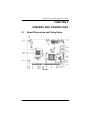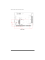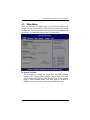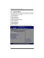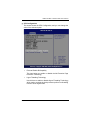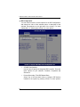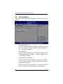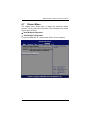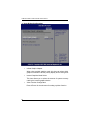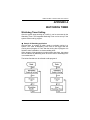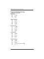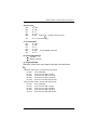
1
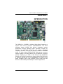
SHB212 Series Intel Atom™ Processor PICMG 1.3 Half-Size Single Board Computer User’s Manual Disclaimers This manual has been carefully checked and believed to contain accurate information. Axiomtek Co., Ltd. assumes no responsibility for any infringements of patents or any third party‟s rights, and any liability arising from such use. Axiomtek does not warrant or assume any legal liability or responsibility for the accuracy completeness or usefulness of any information in this document. Axiomtek does not make any commitment to update the information in this manual. Axiomtek reserves the right to change or revise this document and/or product at any time without notice. No part of this document may be reproduced, stored in a retrieval system, or transmitted, in any form or by any means, electronic, mechanical, photocopying, recording, or otherwise, without the prior written permission of Axiomtek Co., Ltd. Caution If you replace wrong batteries, it causes the danger of explosion. It is recommended by the manufacturer that you follow the manufacturer‟s instructions to only replace the same or equivalent type of battery, and dispose of used ones. Copyright 2011 Axiomtek Co., Ltd. All Rights Reserved April 2011, Version A1 Printed in Taiwan ii ESD Precautions Computer boards have integrated circuits sensitive to static electricity. To prevent chipsets from electrostatic discharge damage, please take care of the following jobs with precautions: Do not remove boards or integrated circuits from their anti-static packaging until you are ready to install them Before holding the board or integrated circuit, touch an unpainted portion of the system unit chassis for a few seconds. It discharges static electricity from your body. Wear a wrist-grounding strap, available from most electronic component stores, when handling boards and components. Trademarks Acknowledgments Axiomtek is a trademark of Axiomtek Co., Ltd. Windows® is a trademark of Microsoft Corporation. AMI is a registered of American Megatrends Inc. IBM, PC/AT, PS/2, VGA are trademarks of International Business Machines Corporation. Intel® and Atom™ are trademarks of Intel Corporation. Winbond is a trademark of Winbond Electronics Corp. Other brand names and trademarks are the properties and registered brands of their respective owners. iii Table of Contents CHAPTER 1 INTRODUTION ............................................................ 1 1.1 Specifications ........................................................................ 2 1.2 Utilities Supported ................................................................. 3 CHAPTER 2 JUMPERS AND CONNECTORS ................................ 5 2.1 Board Dimensions and Fixing Holes .................................... 5 2.2 Board Layout......................................................................... 7 2.3 Jumper Settings .................................................................... 9 2.3.1 COM1 RS-232/422/485 Mode Select (JP1, JP2, JP3) 10 2.3.2 COM1 Data / Power Mode Selection (JP6) ................ 11 2.3.3 COM2 Data / Power Mode Selection (JP5) ................ 12 2.3.4 HD Audio Line Out / Speaker Out Select (JP4) .......... 13 2.3.5 CMOS Clear (JP7) ...................................................... 13 2.3.6 Power On Control Mode (JP8) .................................... 14 2.3.7 USB0,1/USB2,3/USB4,5 Port Power Selection (JP12,JP14,JP10) ....................................................... 14 2.3.8 CompactFlashTM Type Selection (JP11) ..................... 15 2.3.9 LVDS LCD Type Support Selection (JP13) ................ 15 2.4 Connectors.......................................................................... 16 2.4.1 Front Panel Connector (CN1) ..................................... 17 2.4.2 Parallel Port Connector (CN2) .................................... 18 2.4.3 High Definition Audio Connector (CN3) ...................... 19 2.4.4 EPIC Power Connector (CN4) .................................... 19 2.4.5 SMBus Connector (CN5) ............................................ 20 2.4.6 LVDS LCD Connector (CN6) ...................................... 20 2.4.7 LVDS LCD Backlight Connector (CN7) ...................... 21 2.4.8 Serial Port 1 Connector (COM1) ................................. 22 2.4.9 Serial Port 2 Connector (COM2) ................................. 23 2.4.10 CPU & System Fan Connectors (FAN1, FAN2) ......... 23 2.4.11 PS/2 Keyboard Internal Connector (KB1) ................... 24 2.4.12 PS/2 Mouse Internal Connector (MS1) ....................... 24 2.4.13 LAN RJ45 Connector (LAN1, LAN2) .......................... 25 2.4.14 SATA Connectors (SATA1, SATA2) ........................... 25 2.4.15 CompactFlashTM Socket (SCF1) ................................. 26 2.4.16 USB Connector (USB1, USB2) ................................... 28 2.4.17 USB Connector (USB3, USB4) ................................... 28 2.4.18 VGA Connector (VGA1) .............................................. 29 CHAPTER 3 HARDWARE DESCRIPTION .................................... 31 iv 3.1 3.2 3.3 3.4 3.5 3.6 Microprocessors ................................................................. 31 BIOS ................................................................................... 31 System Memory .................................................................. 31 I/O Port Address Map ......................................................... 32 Interrupt Controller .............................................................. 34 Memory Map ....................................................................... 36 CHAPTER 4 AMI BIOS UTILITY .................................................... 39 4.1 Starting ................................................................................ 39 4.2 Navigation Keys .................................................................. 39 4.3 Main Menu .......................................................................... 41 4.4 Advanced Menu .................................................................. 42 4.5 Boot Menu........................................................................... 54 4.6 Security Menu ..................................................................... 58 4.7 Chipset Menu ...................................................................... 59 4.8 Exit Menu ............................................................................ 63 APPENDIX A WATCHDOG TIMER ................................................ 65 Watchdog Timer Setting ............................................................. 65 Using the Watchdog Function .................................................... 66 v MEMO: vi SHB212 PICMG1.3 Half-Size SBC User’s Manual CHAPTER 1 INTRODUCTION The SHB212 is a PICMG1.3 half-size Single Board Computer to support Intel® Atom™ processor N455/D425/D525. The board integrates chipset ICH8-M that delivers outstanding system performance through high-band width interfaces, multiple I/O functions for interactive applications and various embedded computing solutions. There is one 204-pin unbuffered SO-DIMM socket for single channel DDR3-667/800 MHz memory, maximum memory capacity up to 4GB. (N455 is only for DDR3-667, maximum memory capacity up to 2GB). It also features two Gigabit/Fast Ethernet, two Serial ATA channels for total two Serial ATA hard drives at maximum transfer rate up to 150/300MB/sec, six USB 2.0 high speed compliant, built-in High Definition Audio Codec that can achieve the best stability and reliability for industrial applications. INTRODUCTION 1 SHB212 PICMG1.3 Half-Size SBC User’s Manual 1.1 CPU American Megatrends Inc. BIOS. 16Mbit SPI Flash 2 PXE Ethernet Boot ROM. System Memory One 204-pin unbuffered DDR3 SO-DIMM sockets Maximum to 4GB DDR3 667/800 MHz memory for D425/D525 Maximum to 2GB DDR3 667 MHz memory for N455 IDE Interface One CompactFlash™ Type II Socket Two SATA-150/300 connectors USB Interface Intel® ICH8M BIOS Intel® AtomTM processor N455/D425/D525 System Chipset Specifications Six USB ports compliant with USB Spec. Rev. 2.0 (two on the rear I/O, and four ports via wafer connectors) Onboard Multi I/O Controller: Winbond W83627DHG One 26-pin 2.0 pitch box-header for Parallel port One for RS-232/422/485 (COM1) and one port for RS-232 (COM2) Display Support CRT and LVDS LCD output 15-pin D-Sub connector as VGA connector One 40-pin connector for 18 bit single channel LVDS and one 7-pin inverter connector INTRODUCTION SHB212 PICMG1.3 Half-Size SBC User’s Manual Expansion Interface One PCIe x4 or four PCIe x1 I/O Deivces There is no PCIex16 signal. Watchdog Timer Ethernet One port with INTEL 82567V for Gigabit/Fast Ethernet One port with INTEL 82574L for Gigabit/Fast Ethernet Audio HD Audio compliant via Realtek ALC662 Speaker-out/line-out & Line-in & MIC-in via Box Header connector Power Management 1~255 seconds; up to 255 levels ACPI (Advanced Configuration and Power Interface) Dimensions 185mm x 126.39mm All specifications and images are subject to change without notice. 1.2 Utilities Supported Chipset Driver Graphic Driver Ethernet Driver Audio Driver AHCI Driver INTRODUCTION 3 SHB212 PICMG1.3 Half-Size SBC User’s Manual MEMO: 4 INTRODUCTION SHB212 PICMG1.3 Half-Size SBC User’s Manual CHAPTER 2 JUMPERS AND CONNECTORS 2.1 Board Dimensions and Fixing Holes Top Side JUMPERS AND CONNECTORS 5 SHB212 PICMG1.3 Half-Size SBC User’s Manual Bottom Side 6 JUMPERS AND CONNECTORS SHB212 PICMG1.3 Half-Size SBC User’s Manual 2.2 Board Layout Top Side JUMPERS AND CONNECTORS 7 SHB212 PICMG1.3 Half-Size SBC User’s Manual Bottom Side 8 JUMPERS AND CONNECTORS SHB212 PICMG1.3 Half-Size SBC User’s Manual 2.3 Jumper Settings Proper jumer settings configure the SHB212 to meet your application purpose. We are here with listing a summary table of all jumpers and default settings for onboard devices, respectively. Jumper Description Jumper Setting JP1 COM1 RS-232/422/485 setting Default:RS-232 Short 1-2 JP2 COM1 RS-232/422/485 setting Default:RS-232 Short 3-5、4-6 JP3 COM1 RS-232/422/485 setting Default:RS-232 Short 3-5、4-6 JP4 HD Audio Line Out / Speaker Out Select Default:Line Out Short 1-3、2-4 JP5 COM2 Data/Power Mode Select Default:RS-232 Data Short 7-9、8-10 JP6 COM1 Data/Power Mode Select Default:Standby Power Mod Short 7-9、8-10 JP7 CMOS Clear Default:Normal Operation Short 1-2 JP8 Power On Control Mode Default:Power On control by Front Panel Connector Short 1-2 JP10 USB 4,5 Port Power(5V) Selection Default:Standby Power Mode Short 2-3 JP11 CompactFlashTM Type Selection Default:3.3V type CompactFlashTM Support Short 1-2 JP12 USB 0,1 Port Power(5V) Selection Default:Main Power Mode Short 1-2 JP13 LVDS LCD Type Support Selection Default:3.3V type LVDS LCD Support Short 1-2 JP14 USB 2,3 Port Power(5V) Selection Default:Standby Power Mode Short 2-3 JUMPERS AND CONNECTORS 9 SHB212 PICMG1.3 Half-Size SBC User’s Manual 2.3.1 COM1 RS-232/422/485 Mode Select (JP1, JP2, JP3) These jumpers select the communication mode of COM1 port to operate RS-232 or RS-422 or RS-485. When these jumpers are selected to operate RS-422 or RS485, please make sure the COM1 is on Data mode. Function Jumper Setting JP1 JP2 JP3 RS-232 (Default) RS-422 RS-485 10 JUMPERS AND CONNECTORS SHB212 PICMG1.3 Half-Size SBC User’s Manual 2.3.2 COM1 Data / Power Mode Selection (JP6) The COM1 port have +5V or +12V level power capability on DCD and +5V or +12V level power capability for RI, depending on the JP6 setting. Function Jumper Setting COM1 Pin 1 is +12V level COM1 Pin 1 is +5V level COM1 Pin1 is DCD (Default) COM1 Pin 8 is +12V level COM1 Pin 8 is +5V level COM1 Pin 8 is RI (Default) JUMPERS AND CONNECTORS 11 SHB212 PICMG1.3 Half-Size SBC User’s Manual 2.3.3 COM2 Data / Power Mode Selection (JP5) The COM2 port have +5V or +12V level power capability on DCD and +5V or +12V level power capability for RI, depending on the JP5 setting. Function Jumper Setting COM2 Pin 1 is +12V level COM2 Pin 1 is +5V level COM2 Pin 1 is DCD (Default) COM2 Pin 8 is +12V level COM2 Pin 8 is +5V level COM2 Pin 8 is RI (Default) 12 JUMPERS AND CONNECTORS SHB212 PICMG1.3 Half-Size SBC User’s Manual 2.3.4 HD Audio Line Out / Speaker Out Select (JP4) This jumper is to select which source for the audio output (CN3). When the Speaker Out is set, it delivers 2W/channel continuous into 8 Ohm loads. Function Jumper Setting Line Out (Default) Speak Out with Amplifier 2.3.5 CMOS Clear (JP7) You may need to use this jumper is to clear the CMOS memory if incorrect settings in the Setup Utility. Function Jumper Setting Normal (Default) Clear CMOS JUMPERS AND CONNECTORS 13 SHB212 PICMG1.3 Half-Size SBC User’s Manual 2.3.6 Power On Control Mode (JP8) The Power On Control mode provides two kinds of power on mode as follows, Function Jumper Setting Power On control by Front Panel Connector (Default) Power On control by Power Supply 2.3.7 USB0,1/USB2,3/USB4,5 Port Power Selection (JP12,JP14,JP10) USB Power provides two kinds of mode as follows: Main power Mode: USB device has power only when system power is on. Standby Power Mode: USB device has power on both standby and power-on. Function Jumper Setting Main Power Mode (Default) Standby Power Mode 14 JUMPERS AND CONNECTORS SHB212 PICMG1.3 Half-Size SBC User’s Manual 2.3.8 CompactFlashTM Type Selection (JP11) Function Jumper Setting 3.3V type CompactFlash TM support (Default) 5V type Compact Flash TM support 2.3.9 LVDS LCD Type Support Selection (JP13) The board supports 3.3V or 5V type LCD displays. Function Jumper Setting 3.3V type LVDS LCD support (Default) 5V type LVDS LCD support JUMPERS AND CONNECTORS 15 SHB212 PICMG1.3 Half-Size SBC User’s Manual 2.4 Connectors Connectors connect the board with other parts of the system. Loose or improper connection might cause problems.Make sure all connectors are properly and firmly connected. Here is a summary table which shows you all connectors on the SHB212 Series. Connectors 16 Label Front Panel Bezel Connector CN1 Parallel Port Connector CN2 High Definition Audio Connector CN3 EPIC Power Connector CN4 SMBus Connector CN5 LVDS LCD Connector CN6 LVDS LCD Backlight Connector CN7 Serial Port1 Connector COM1 Serial Port2 Connector COM2 CPU Fan Connector FAN1 System Fan Connector FAN2 PS/2 Keyboard Internal Connector KB1 PS/2 Mouse Internal Connector MS1 LAN RJ45 Connector LAN1 LAN RJ45 Connector LAN2 SATA Connector SATA1 SATA Connector SATA2 CompactFlashTM TypeII Socket SCF1 JUMPERS AND CONNECTORS SHB212 PICMG1.3 Half-Size SBC User’s Manual Connectors Label USB Connector USB1 USB Connector USB2 USB Connector USB3 USB Connector USB4 VGA Connector VGA1 2.4.1 Front Panel Connector (CN1) Power LED This 3-pin pin-header, designated at Pins 1 and 5 of CN1, connects the system power LED indicator to its respective switch on the case. Pin 1 is +, and pin 5 is assigned as -. The Power LED lights up when the system is powered ON.Pin 3 is defined as GND. External Speaker and Internal Buzzer Connector Pins 2, 4, 6, and 8 of CN1 connect to the case-mounted speaker unit or internal buzzer. When connecting to an internal buzzer and Short pin2 and pin4. When connecting an external speaker, set these jumpers to Open and install the speaker cable on pin 8 (+) and pin 2 (-). Power On/Off Button This 2-pin pin-header, designated at Pins 9 and 10 of CN1, connects the power button on the front panel to the CPU board, allowing user to control the power on/off state of the power supply. System Reset Switch Pins 11 and 12 of CN1 connect to the case-mounted reset switch and allow rebooting of your computer instead of turning OFF the power switch. This is a preferred method of rebooting in order to prolong the life of the system‟s power supply. JUMPERS AND CONNECTORS 17 SHB212 PICMG1.3 Half-Size SBC User’s Manual HDD Activity LED This connector extends to the hard drive activity LED on the control panel. This LED will flash when the HDD is being accessed. Pins 13 and 14 of CN1 connect the hard disk drive and the front panel HDD LED. Pins 13 is -, and pin 14 is assigned as +. 2.4.2 Parallel Port Connector (CN2) This board has a multi-mode parallel port to support the following modes: 1. Standard Mode IBM PC/XT, PC/AT and PS/2 are compatible with bi-directional parallel port. 2. Enhanced Mode Enhanced parallel port (EPP) is compatible with EPP 1.7 and EPP 1.9 (IEEE 1284 compliant). 3. High Speed Mode Microsoft and Hewlett Packard extended capabilities port (ECP) is IEEE 1284 compliant. Pin 1 3 5 7 9 11 13 15 17 19 21 23 25 18 Signal Strobe# Data 0 Data 1 Data 2 Data 3 Data 4 Data 5 Data 6 Data 7 Acknowledge# Busy Paper Empty# Printer Select Pin 2 4 6 8 10 12 14 16 18 20 22 24 26 Signal Auto Form Feed# Error# Initialize# Printer Select In# GND GND GND GND GND GND GND GND N.C JUMPERS AND CONNECTORS SHB212 PICMG1.3 Half-Size SBC User’s Manual 2.4.3 High Definition Audio Connector (CN3) CN3 is a 10-pin 2.0pitch box-header to support the audio interface. Pin 7 and Pin 9 can be referred to JP13 Jumper Setting to set the audio source. Pin Signal Pin Signal 1 MIC-IN 2 GND 3 Line In L 4 GND 5 Line In R 6 GND 7 Audio Out L 8 GND 9 Audio Out R 10 GND 2.4.4 EPIC Power Connector (CN4) Steady and sufficient power can be supplied to all components on the board through the power connector. Please make sure all components and devices are properly installed before connecting the power connector. Pin Signal Pin Signal 1 PS_ON 2 GND 3 GND 4 +12V 5 +3.3V 6 5VSB 7 N.C 8 N.C 9 N.C 10 GND JUMPERS AND CONNECTORS 19 SHB212 PICMG1.3 Half-Size SBC User’s Manual 2.4.5 SMBus Connector (CN5) Connector CN5 is for SMBus interface support. Pin Signal 1 CLOCK 2 DATA 3 GND 2.4.6 LVDS LCD Connector (CN6) The board has a 40-pin connector CN6 for LVDS LCD Interface. It is strongly recommended to use the matching GLA1001WV-S-2X20P 40pin connector for LVDS LCD on the board.Pin1~6 VCCM can be set +3.3V level or +5V level by JP14 Pin 20 Signal Pin Signal 1 VCCM 2 VCCM 3 VCCM 4 VCCM 5 VCCM 6 VCCM 7 N.C 8 N.C 9 GND 10 GND 11 N.C 12 N.C 13 N.C 14 N.C 15 GND 16 GND 17 N.C 18 N.C 21 GND 22 GND 23 Channel A D0- 24 N.C 25 Channel A D0+ 26 N.C 27 GND 28 GND 29 Channel A D1- 30 N.C JUMPERS AND CONNECTORS SHB212 PICMG1.3 Half-Size SBC User’s Manual Pin Signal Pin Signal 31 Channel A D1+ 32 N.C 33 GND 34 GND 35 Channel A D2- 36 Channel A CLK- 37 Channel A D2+ 38 Channel A CLK+ 39 GND 40 GND 2.4.7 LVDS LCD Backlight Connector (CN7) The 7-pin inverter connector on the SHB212 is with Hirose connector. The matching connector is strongly recommended to use Hirose DF137S-1.25C. Pin Signal 1 12V(Only for LCD) 2 12V(Only for LCD) 3 5V(Only for LCD) 4 ENABLE 5 GND 6 GND 7 GND JUMPERS AND CONNECTORS 21 SHB212 PICMG1.3 Half-Size SBC User’s Manual 2.4.8 Serial Port 1 Connector (COM1) COM1 is a 10-pin 2.0pitch box-header. This port is with +5V level or +12V level power capability for DCD and RI, depending on the JP6 jumper setting. The pin assignment of RS-232/RS-422/RS485 is listed on the following table. If you need COM1 port to support RS-422 or RS-485, Pin RS-232 RS-422 RS-485 1 Data Carrier Detect (DCD) Transmit Data (TX-) Data - 2 Data Set Ready (DSR) N.C N.C 3 Receive Data (RX) Transmit Data + (TX+) Data + 4 Request to Send (RTS) N.C N.C 5 Transmit Data (TX) Receive Data + (RX+) N.C 6 Clear to Send (CTS) N.C N.C 7 Data Terminal Ready (DTR) Receive Data (RX-) N.C 8 Ring Indicator (RI) N.C N.C 9 Ground (GND) N.C N.C 10 N.C N.C N.C 22 JUMPERS AND CONNECTORS SHB212 PICMG1.3 Half-Size SBC User’s Manual 2.4.9 Serial Port 2 Connector (COM2) COM2 is a 10-pin 2.0pitch box-header.This port is with +5V level or +12V level power capability for DCD and RI, depending on the JP5 jumper setting Pin Signal Pin Signal 1 Data Carrier Detect (DCD) 2 Data Set Ready (DSR) 3 Receive Data (RX) 4 Request to Send (RTS) 5 Transmit Data (TX) 6 Clear to Send (CTS) 7 Data Terminal Ready (DTR) 8 Ring Indicator (RI) 9 Ground (GND) 10 N.C 2.4.10 CPU & System Fan Connectors (FAN1, FAN2) FAN1 is a fan connector for CPU and FAN2 for system. Pentium microprocessors require a fan for heat dispensing. The CPU/System fan connectors respectively provide power to the CPU/System fans. You can find the fan speed on the BIOS Setup Utility when the fan is installed. (See BIOS Setup Utility:Advanced → Hardware Health). Pin Signal 1 GND 2 Fan Power 3 Sensor JUMPERS AND CONNECTORS 23 SHB212 PICMG1.3 Half-Size SBC User’s Manual 2.4.11 PS/2 Keyboard Internal Connector (KB1) The board provides the Internal Keyboard interface with a 5-pin wafer connector. Pin Signal 1 Keyboard Clock 2 Keyboard Data 3 N.C 4 GND 5 Power For K/B 2.4.12 PS/2 Mouse Internal Connector (MS1) The board provides the Internal Mouse interface with a 5-pin wafer connector. Pin Signal 24 1 Mouse Clock 2 Mouse Data 3 N.C 4 GND 5 Power For M/S JUMPERS AND CONNECTORS SHB212 PICMG1.3 Half-Size SBC User’s Manual 2.4.13 LAN RJ45 Connector (LAN1, LAN2) To connect the board to a 1000/100/10 Base-T hub, just plug one end of the cable into LAN1/LAN2, and connect the other end to a 1000/100/10 Base-T hub. Pin 1 MDI0+ Signal Pin 2 MDI0- Signal 3 MDI1+ 4 MDI2+ 5 MDI2- 6 MDI1- 7 MDI3+ 8 MDI3- A Active LED (Yellow) B 100 LAN LED (Green)/ 1000 LAN LED (Orange) 2.4.14 SATA Connectors (SATA1, SATA2) The SATA connectors SATA1 and SATA2 are for high-speed SATA interface port and it can be connected to serial ATA hard disk devices. Pin Signal Pin Signal 1 GND 2 SATA TX+ 3 SATA TX- 4 GND 5 SATA RX- 6 SATA RX+ 7 GND JUMPERS AND CONNECTORS 25 SHB212 PICMG1.3 Half-Size SBC User’s Manual 2.4.15 CompactFlashTM Socket (SCF1) The board is equipped with a CompactFlashTM disk type-II socket on the solder side to support an IDE interface CompactFlashTM disk card with DMA mode supported. The socket is especially designed to avoid incorrect installation of the CompactFlashTM disk card. When installing or removing the CompactFlashTM disk card, please make sure the system power is off. Pin13 and Pin38 power voltage can be referred to JP11 Jumper Setting Pin Signal Pin Signal 1 GND 2 Data 3 3 Data 4 4 Data 5 5 Data 6 6 Data 7 7 CS0- 8 GND 9 ATASEL 10 GND 11 GND 12 GND 13 VCC 14 GND 15 GND 16 GND 17 GND 18 Address 2 23 Data 2 24 IOCS16- 25 GND 26 CD1- 27 Data 11 28 Data 12 29 Data 13 30 Data 14 31 Data 15 32 CS1- 33 VS1- 34 IORD- 35 IOWR- 36 WE# 26 JUMPERS AND CONNECTORS SHB212 PICMG1.3 Half-Size SBC User’s Manual Pin Signal Pin Signal 37 INTR 38 VCC 39 CSEL- 40 VS2- 41 RESET- 42 IORDY- 43 DMAREQ 44 DMAACK- 45 DASP- 46 PDIAG- 47 Data 8 48 Data 9 49 Data 10 50 GND JUMPERS AND CONNECTORS 27 SHB212 PICMG1.3 Half-Size SBC User’s Manual 2.4.16 USB Connector (USB1, USB2) The board features Universal Serial Bus (USB) connectors, compliant with USB 2.0 (480Mbps) that can be adapted to any USB peripherals, such as monitor, keyboard and mouse. USB1, USB2 is a singal-deck USB port connector that consists of two 4-pin standard USB ports. Pin Signal Pin Signal 1 USB POWER 2 USB DATA- 3 USB DATA+ 4 GND 2.4.17 USB Connector (USB3, USB4) The board features Universal Serial Bus (USB) connectors, compliant with USB 2.0 (480Mbps) that can be adapted to any USB peripherals, such as monitor, keyboard and mouse. USB3 is a 10-pin 2.0pitch wafer connector. Pin Signal Pin Signal 28 1 USB POWER 2 USB POWER 3 USB DATA(A)- 4 USB DATA(B)- 5 USB DATA(A)+ 6 USB DATA(B)+ 7 GND 8 GND 9 GND 10 GND JUMPERS AND CONNECTORS SHB212 PICMG1.3 Half-Size SBC User’s Manual 2.4.18 VGA Connector (VGA1) VGA1 is a slim type 15-pin D-Sub connector which is common for CRT VGA display. The interface configuration can be configured via the software utility. Pin Signal Pin Signal Pin Signal 1 RED 2 GREEN 3 BLUE 4 N.C 5 GND 6 DETECT 7 GND 8 GND 9 Power 10 GND 11 N.C 12 DDC DATA 13 Horizontalync 14 Vertical Sync 15 DDC CLOCK JUMPERS AND CONNECTORS 29 SHB212 PICMG1.3 Half-Size SBC User’s Manual MEMO: 30 JUMPERS AND CONNECTORS SHB212 PICMG1.3 Half-Size SBC User’s Manual CHAPTER 3 HARDWARE DESCRIPTION 3.1 Microprocessors The SHB212 Series supports Intel® Atom™ processor N455/D425/ D525, which make your system operated under Windows XP/Vista and Windows 7 environments. The system performance depends on the microprocessor. 3.2 BIOS The SHB212 Series uses American Megatrends BIOS with 16Mbit SPI Flash, DMI, Plug and Play. 3.3 System Memory The SHB212 Series industrial CPU card supports one 204-pin unbuffered DDR3 SO-DIMM socket for a maximum memory of 4GB DDR3 SDRAM (N455 is only for DDR3-667, maximum memory capacity up to 2GB). HARDWARE DESCRIPTION 31 SHB212 PICMG1.3 Half-Size SBC User’s Manual 3.4 I/O Port Address Map There are total 1KB port addresses (under OS WinXP) available for assignment to other devices via I/O expansion cards. Address Devices 0000-000F 0081-0083 0087 0089-008B Direct Memory Access controller 008F 00C0-00DF 0000-0CF7 0D00-FFFF 0020-0021 00A0-00A1 PCI Bus Interrupt controller 0040-0043 System timer 0060 0064 Standard 101/102 Key or Microsoft Natural PS/2 Keyboard 0061 System speaker 0070-0071 System CMOS/Real time clock 01F0-01F7 03F6 Primary IDE Channel 0274-0277 0279 ISAPNP Read Data Port 0A79 02F8-02FF Communications Port (COM2) 0378-037F Printer Port (LPT1) 32 HARDWARE DESCRIPTION SHB212 PICMG1.3 Half-Size SBC User’s Manual Address Devices 03B0-03BB 03C0-03DF Intel® Graphics Media Accelerator 3150 C000-C007 03F8-03FF Communications Port (COM1) 0400-041F Intel® ICH8 Family SMBus Controller C080-C09F Intel® 82567V-3 Gigabit Network Connection C400-C41F C480-C49F C800-C81F Intel® ICH8 Family USB Universal Host Controller C880-C89F CC00-CC1F D080-D08F D400-D40F D480-D483 D800-D807 Intel® ICH8M 3Port Serial ATA Storage Controller D880-D883 DC00-DC07 E000-EFFF Intel® ICH8 Family PCI Express Root Port 5 EC00-EC1F Intel® 82574L Gigabit Network Connection FFA0-FFAF Intel® ICH8M Family Ultra ATA Storage Controllers HARDWARE DESCRIPTION 33 SHB212 PICMG1.3 Half-Size SBC User’s Manual 3.5 Interrupt Controller The SHB212 Series is a 100% PC compatible control board. It consists of 16 interrupt request lines, and four out of them can be programmable. The mapping list of the 16 interrupt request lines is shown as the following table. IRQ 34 Parity check error IRQ0 System timer output IRQ1 Standard 101/102 Key or Microsoft Natural PS/2 Keyboard IRQ3 Communication Port (COM2) IRQ4 Communication Port (COM1) IRQ8 System CMOS/Real time clock IRQ9 Microsoft ACPI-Compliant System IRQ11 Intel® ICH8 Family SMBus Controller IRQ12 Microsoft PS/2 Mouse IRQ13 Numeric data processor IRQ14 Primary IDE Channel IRQ16 Intel® 82574L Gigabit Network Connection IRQ16 Intel® Graphics Media Accelerator 3150 IRQ16 Intel® ICH8 Family USB Universal Host Controller IRQ18 Intel® ICH8 Family USB Universal Host Controller IRQ18 Intel® ICH8 Family USB2 Enhanced Host Controller IRQ18 Intel® ICH8M 3 Port Serial ATA Storage Controller IRQ19 Intel® ICH8 Family USB Universal Host Controller IRQ21 Intel® ICH8 Family USB Universal Host Controller IRQ21 Microsoft UAA Bus Driver for High Definition Audio HARDWARE DESCRIPTION SHB212 PICMG1.3 Half-Size SBC User’s Manual IRQ Parity check error IRQ22 Intel® ICH8 Family PCI Express Root Port 1 IRQ22 Intel® ICH8 Family PCI Express Root Port 5 IRQ23 Intel® 82567V-3 Gigabit Network Connection IRQ23 Intel® ICH8 Family USB Universal Host Controller IRQ23 Intel® ICH8 Family USB2 Enhanced Host Controller HARDWARE DESCRIPTION 35 SHB212 PICMG1.3 Half-Size SBC User’s Manual 3.6 Memory Map Address Devices 000000000009FFFF System board 000A0000000BFFFF Intel® Graphics Media Accelerator 3150 000A0000000BFFFF PCI Bus 000C0000000CFFFF System board 000D0000000DFFFF PCI Bus 000E0000000FFFFF System board 001000007F6FFFFF System board 7F700000 DFFFFFFF PCI Bus D0000000DFFFFFFF Intel® Graphics Media Accelerator 3150 F0000000 FED8FFFF PCI Bus FE880000– FEA7FFFF Intel® Graphics Media Accelerator 3150 FEAC0000– FEADFFFF Intel® 82567V-3 Gigabit Network Connection FEAF8000– FEAFBFFF Microsoft UAA Bus Driver for High Definition Audio FEAFF400– FEAFFBFF Intel® ICH8 Family USB2 Enhanced Host Controller 36 HARDWARE DESCRIPTION SHB212 PICMG1.3 Half-Size SBC User’s Manual Address Devices FEAFFC00– Intel® ICH8 Family SMBus Controller FEAFFCFF FEB00000– FEBFFFFF Intel® ICH8 Family PCI Express Root Port 5 FEBDC000– Intel® 82574L Gigabit Network Connection FEBFFFFF FED14000FED19FFF System board FED90000FFFFFFFF System board FFB00000FFBFFFFF Intel® 82802 Firmware Hub Device FFF00000FFFFFFFF Intel® 82802 Firmware Hub Device HARDWARE DESCRIPTION 37 SHB212 PICMG1.3 Half-Size SBC User’s Manual MEMO: 38 HARDWARE DESCRIPTION SHB212 PICMG1.3 Half-Size SBC User’s Manual CHAPTER 4 AMI BIOS UTILITY This chapter provides users with detailed description how to set up basic system configuration through the AMIBIOS8 BIOS setup utility. 4.1 Starting To enter the setup screens, follow the steps below: Turn on the computer and press the <Del> key immediately. After you press the <Delete> key, the main BIOS setup menu displays. You can access the other setup screens from the main BIOS setup menu, such as the Chipset and Power menus. 4.2 Navigation Keys The BIOS setup/utility uses a key-based navigation system called hot keys. Most of the BIOS setup utility hot keys can be used at any time during the setup navigation process. These keys include <F1>, <F10>, <Enter>, <ESC>, <Arrow> keys, and so on. Some of navigation keys differ from one screen to another. AMI BIOS UTILITY 39 SHB212 PICMG1.3 Half-Size SBC User’s Manual Left/Right The Left <Arrow> keys allow you to select a setup screen. Up/Down The Up and Down <Arrow> keys allow you to select a setup screen or sub-screen. + Plus/Minus The Plus and Minus <Arrow> keys allow you to change the field value of a particular setup item. Tab The <Tab> key allows you to select setup fields. F1 The <F1> key allows you to display the General Help screen. F10 The <F10> key allows you to save any changes you have made and exit Setup. Press the <F10> key to save your changes. Esc Enter 40 The <Esc> key allows you to discard any changes you have made and exit the Setup. Press the <Esc> key to exit the setup without saving your changes. The <Enter> key allows you to display or change the setup option listed for a particular setup item. The <Enter> key can also allow you to display the setup sub- screens. AMI BIOS UTILITY SHB212 PICMG1.3 Half-Size SBC User’s Manual 4.3 Main Menu When you first enter the Setup Utility, you will enter the Main setup screen. You can always return to the Main setup screen by selecting the Main tab. There are two Main Setup options. They are described in this section. The Main BIOS Setup screen is shown below. System Time/Date Use this option to change the system time and date. Highlight System Time or System Date using the <Arrow> keys. Enter new values through the keyboard. Press the <Tab> key or the <Arrow> keys to move between fields. The date must be entered in MM/DD/YY format. The time is entered in HH:MM:SS format. AMI BIOS UTILITY 41 SHB212 PICMG1.3 Half-Size SBC User’s Manual 4.4 Advanced Menu The Advanced menu allows users to set configuration of the CPU and other system devices. You can select any of the items in the left frame of the screen to go to the sub menus: CPU Configuration IDE Configuration SuperIO Configuration Hardware Health Configuration ACPI Configuration AHCI Configuration APM Configuration USB Configuration For items marked with “”, please press <Enter> for more options. 42 AMI BIOS UTILITY SHB212 PICMG1.3 Half-Size SBC User’s Manual CPU Configuration This screen shows the CPU Configuration, and you can change the value of the selected option. Execute-Disable Bit Capability This item helps you enable or disable the No-Execution Page Protection Technology Hyper Threading Technology Use this item to enable or disable Hyper-Threading Technology, which makes a single physical processor perform multi-tasking function as two logical ones. AMI BIOS UTILITY 43 SHB212 PICMG1.3 Half-Size SBC User’s Manual IDE Configuration You can use this screen to select options for the IDE Configuration, and change the value of the selected option. A description of the selected item appears on the right side of the screen. For items marked with “”, please press <Enter> for more options. ATA/IDE Configuration Use this item to specify the integrated IDE controller. There are three options for your selection: Disabled, Compatible and Enhanced. Primary/Secondary /Third IDE Master/Slave Select one of the hard disk drives to configure IDE devices installed in the system by pressing <Enter> for more options. 44 AMI BIOS UTILITY SHB212 PICMG1.3 Half-Size SBC User’s Manual SuperIO Configuration You can use this screen to select options for the SuperIO Configuration, and change the value of the selected option. A description of the selected item appears on the right side of the screen. OnBoard Floppy Controller Use this item to enable or disable the onboard floppy drive controller. Serial Port1 Address This item specifies the base I/O port address and Interrupt Request address of serial port 1. The Optimal setting is 3F8/IRQ4. The Fail-Safe default setting is disabled. AMI BIOS UTILITY 45 SHB212 PICMG1.3 Half-Size SBC User’s Manual Serial Port2 Address This item specifies the base I/O port address and Interrupt Request address of serial port 2. The Optimal setting is 2F8/IRQ3. The Fail-Safe setting is disabled. Parallel Port Address This item allows you to determine the I/O address for onboard parallel port. There are several options for your selection. Parallel Port Mode Select an operating mode for the onboard parallel (printer) port. Parallel Port IRQ Use this item to set up the IRQ for onboard parallel port. 46 AMI BIOS UTILITY SHB212 PICMG1.3 Half-Size SBC User’s Manual Hardware Health Configuration This screen shows the Hardware Health CPU Configuration, and a description of the selected item appears on the right side of the screen. System Temperature/CPU Temperature These items display the temperature of CPU and System, Vcore, etc AMI BIOS UTILITY 47 SHB212 PICMG1.3 Half-Size SBC User’s Manual ACPI Configuration You can use this screen to select options for the ACPI Configuration, and change the value of the selected option. A description of the selected item appears on the right side of the screen. 48 AMI BIOS UTILITY SHB212 PICMG1.3 Half-Size SBC User’s Manual General ACPI Configuration Scroll to this item and press <Enter> to view the General ACPI Configuration sub menu, which contains General ACPI (Advanced Configuration and Power Management Interface) options for your configuration. AMI BIOS UTILITY 49 SHB212 PICMG1.3 Half-Size SBC User’s Manual AHCI Configuration Use this screen to select options for the AHCI Configuratio and change the value of the selected option. 50 AMI BIOS UTILITY SHB212 PICMG1.3 Half-Size SBC User’s Manual APM Configuration You can use this screen to select options for the APM Configuration, and change the value of the selected option.A description of the selected item appears on the right side of the screen. Power Management/APM Set this item to allow Power Management/APM support.The default setting is Enabled. Disabled Set this item to prevent the chipset power management and APM (Advanced Power Management) features. Enabled Set this item to allow the chipset power management and APM (Advanced Power Management) features. This is the default setting. AMI BIOS UTILITY 51 SHB212 PICMG1.3 Half-Size SBC User’s Manual Video Power Down Mode This option specifies the Power State that the video subsystem enters when the BIOS places it in a power saving state after the specified period of display inactivity has expired. The default setting is Suspend. Disabled This setting prevents the BIOS from initiating any power saving modes concerned with the video display or monitor. Suspend This option places the monitor into suspend mode after the specified period of display inactivity has expired. This means the monitor is not off. The screen will appear blacked out. The standards do not cite specific power ratings because they vary from monitor to monitor, but this setting use less power than Standby mode. This is the default setting. Power Button Mode This option specifies how the externally mounted power button on the front of the computer chassis is used.The default setting is On/Off. On/Off Pushing the power button turns the computer on or off. This is the default setting. This is the default setting. Suspend Pushing the power button places the computer in Suspend mode or Full On power mode. ***** Advanced Resume Event Controls ***** 52 AMI BIOS UTILITY SHB212 PICMG1.3 Half-Size SBC User’s Manual Resume On Ring This item enables or disables the function of Resume On Ring that resumes the system through incoming calls. Resume On RTC Alarm You can set “Resume On RTC Alarm” item to enabled and key in Data/time to power on system. USB Configuration You can use this screen to select options for the USB Configuration, and change the value of the selected option. A description of the selected item appears on the right side of the screen. USB Fuction Use this item to enable or disable USB function. USB 2.0 Controller Mode Use this item to configure the USB 2.0 controller. AMI BIOS UTILITY 53 SHB212 PICMG1.3 Half-Size SBC User’s Manual 4.5 Boot Menu The Boot menu allows users to change boot options of the system. You can select any of the items in the left frame of the screen to go to the sub menus: Boot Settings Configuration Lan Boot Option For items marked with “”, please press <Enter> for more options. 54 AMI BIOS UTILITY SHB212 PICMG1.3 Half-Size SBC User’s Manual Boot Settings Configuration Quick Boot Enabling this item lets the BIOS skip some power on self tests (POST).The default setting is Enabled. Boot Num-Lock Use this item to select the power-on state for the NumLock. The default setting is On. Wait For „F1‟ Of Error If this item is enabled, the system waits for the F1 key to be pressed when error occurs. The default setting is Enabled. Hit „DEL‟ Message Display If this item is enabled, the system displays the message “Press DEL to run Setup” during POST. The default setting is Enabled. AMI BIOS UTILITY 55 SHB212 PICMG1.3 Half-Size SBC User’s Manual Boot Device Priority The Boot Device Priorityh screen specifies the boot device priority sequence from the available devices. LAN Boot Option Use these items to enable or disable the Boot ROM function of the onboard LAN chip when the system boots up.Available options of the selected item appear on the right side of the screen. LAN1 GbE Controller This item allows you to Enabled or Disabled Intel® LAN Contrller. GbE LAN Boot This item allows you to Enabled or Disabled Intel® WG82567V LAN Boot ROM . 56 AMI BIOS UTILITY SHB212 PICMG1.3 Half-Size SBC User’s Manual GbE Wake Up From S5 This item specifies whether the system will be awakened from the S5 power. LAN 2 Boot This item allows you to Enabled or Disabled Intel® WG82574L LAN Boot ROM. AMI BIOS UTILITY 57 SHB212 PICMG1.3 Half-Size SBC User’s Manual 4.6 Security Menu The Security menu allows users to change the security settings for the system. Supervisor Password This item indicates whether a supervisor password has been set. If the password has been installed, Installed」displays. If not, 「Not Installe」displays User Password This item indicates whether a user password has been set. If the password has been installed, 「Installed」displays. If not, 「Not Installed」displays. Change Supervisor Password Select this option and press <Enter> to access the sub menu. You can use the sub menu to change the supervisor password. Change User Password Select this option and press <Enter> to access the sub menu. You can use the sub menu to change the user password. 58 AMI BIOS UTILITY SHB212 PICMG1.3 Half-Size SBC User’s Manual 4.7 Chipset Menu The Chipset menu allows users to change the advanced chipset settings. You can select any of the items in the left frame of the screen to go to the sub menus: North Bridge Configuration South Bridge Configuration For items marked with “”, please press <Enter> for more options. AMI BIOS UTILITY 59 SHB212 PICMG1.3 Half-Size SBC User’s Manual North Bridge Configuration Initiate Graphic Adapter When using multiple graphics cards, this item can select which graphics controller to be the primary display device during boot. Internal Graphics Mode Select This item allows you to select the amount of system memory used by the internal graphics device. Video Function Configuration Press <Enter> for the sub-menu for setting up video function. 60 AMI BIOS UTILITY SHB212 PICMG1.3 Half-Size SBC User’s Manual Video Function Configuration DVMT Mode Select Allow you to select DVMT (Dianomic Technology) mode and Fixed Mode. Video Memory DVMT/FIXED Memory Allow you to allocate a fixed amount of system memory as graphics memory. Here are the options for your selection, 128MB, 256MB and Maximum DVMT AMI BIOS UTILITY 61 SHB212 PICMG1.3 Half-Size SBC User’s Manual South Bridge Configuration HDA Controller This item allows you to Enable or Disable the HD audio support. PCIE Port Configuration This item allows you to set or disable the PCI Express Ports. PCI Express Port Mode This item allows choosing the X1 or X4 on PCIE 0 to PCIE3 62 AMI BIOS UTILITY SHB212 PICMG1.3 Half-Size SBC User’s Manual 4.8 Exit Menu The Exit menu allows users to load your system configuration with optimal or failsafe default values. Save Changes and Exit When you have completed the system configuration changes, select this option to leave Setup and reboot the computer so the new system configuration parameters can take effect. Select Save Changes and Exit from the Exit menu and press <Enter>. Select Ok to save changes and exit. Discard Changes and Exit Select this option to quit Setup without making any permanent changes to the system configuration. Select Discard Changes and Exit from the Exit menu and press <Enter>. Select Ok to discard changes and exit. AMI BIOS UTILITY 63 SHB212 PICMG1.3 Half-Size SBC User’s Manual Load Optimal Defaults It automatically sets all Setup options to a complete set of default settings when you select this option. The Optimal settings are designed for maximum system performance, but may not work best for all computer applications. In particular, do not use the Optimal Setup options if your computer is experiencing system configuration problems. Select Load Optimal Defaults from the Exit menu and press <Enter>. Load Fail-Safe Defaults It automatically sets all Setup options to a complete set of default settings when you select this option. The Fail-Safe settings are designed for maximum system stability, but not maximum performance. Select the Fail-Safe Setup options if your computer is experiencing system configuration problems. Select Load Fail-Safe Defaults from the Exit menu and press <Enter>. Select Ok to load Fail-Safe defaults. 64 AMI BIOS UTILITY SHB212 PICMG1.3 Half-Size SBC User’s Manual APPENDIX A WATCHDOG TIMER Watchdog Timer Setting After the system stops working for a while, it can be auto-reset by the Watchdog Timer. The integrated Watchdog Timer can be set up in the system reset mode by program. Sample of Watchdog application Assume there is program A which needs to maintain running in a system. The value of Watchdog Timer must be set bigger than the running time of program A. Then, after the running time of program A is finished, either to disable or to reset watchdog timer. When program A has problems to make system shut down, the system can be rebooted by Watchdog timer when the value of watchdog timer is countdowned to 0. The below flowchart can be referred to edit program A. WATCHDOG TIMER 65 SHB212 PICMG1.3 Half-Size SBC User’s Manual Using the Watchdog Function Assembler Sample Code ;Enable WDT: Mov dx , 2Eh Mov al , 87h Out dx , al Out dx , al ;Select Logic device: Mov dx , 2Eh Mov al , 07h Out dx , al Mov dx , 2Fh Mov al , 08h Out dx , al ;Set WDT Function: Mov dx , 2Eh Mov al , 2Dh Out dx , al Mov dx , 2Fh Mov al , 20h Out dx , al ;Activate WDT: Mov dx , 2Eh Mov al , 30h Out dx , al Mov dx , 2Fh Mov al , 01h Out dx , al ;Set Second or Minute: Mov dx , 2Eh Mov al , F5h Out dx , al Mov dx , 2Fh Mov Out 66 al , Nh ;N=00 or 08(See below dx al ) WATCHDOG TIMER SHB212 PICMG1.3 Half-Size SBC User’s Manual ;Set base timer: Mov dx , 2Eh Mov al , F6h Out dx , al Mov dx , 2Fh Mov al , Mh Out M=00,01,02,…FF(Hex) ,Value=0 to 255 dx , al ; (See below ; IF to disable WDT: Mov dx , 2Eh Mov al , 30h Out dx , al Mov dx , 2Fh Mov al , 00h Out dx , al ) ; Can be disable at any time imeout Value Range 1 to 255 Minute / Second Program Sample Watchdog Timer can be set to system reset after 5-second timeout. : When N‟s value is 00h , the time base is set second. M = 00h: Time-out Disable. M = 01h: Time-out occurs after 1 second. M = 02h: Time-out occurs after 2 seconds. M = 03h: Time-out occurs after 3 seconds.. M = FFh: Time-out occurs after 255 seconds. When N‟s value is 08h , the time base is set minute. M = 00h: Time-out Disable. M = 01h: Time-out occurs after 1 minute. M = 02h: Time-out occurs after 2 minutes. M = 03h: Time-out occurs after 3 minutes. M = FFh: Time-out occurs after 255 minutes. WATCHDOG TIMER 67