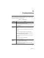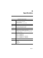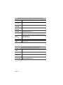
1
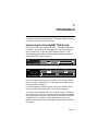
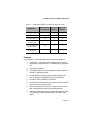
FriendlyNET 7000 Series
Gigabit Ethernet Switches
User’s Manual
Copyright Notice
Trademarks
Asanté Technologies and FriendlyNET are trademarks of Asanté Technologies, Inc. Ethernet is a registered
trademark of the Xerox Corporation. All brand names and products are trademarks or registered trademarks of their respective holders.
FCC Information
This device complies with part 15 of the FCC Rules. Operation is subject to the following two conditions:
(1) this device may not cause harmful interference and (2) this device must accept any interference received,
including interference that may cause undesired operation.
Operation of this equipment in a residential area is likely to cause interference, in which case, the user, at
his or her own risk and expense, will be required to correct the interference.
FIVE YEAR LIMITED WARRANTY
Subject to the limitations and exclusions below, Asanté warrants to the original end user purchaser that the
covered products will be free from defects in materials and manufacturing workmanship for a period of 5
years from date of purchase. This warranty excludes fans, power supplies and accessories. Asanté warrants
that the fans and power supplies contained in covered products will be free from defects in materials and
manufacturing workmanship for one year from date of purchase.
To take advantage of this warranty, you must:
(1)contact Asanté for a return materials authorization (RMA) number. The RMA number must be clearly
written on the outside of the returned package.(2)Product must be sent to Asanté postage paid. (3)Provide
Asanté with proof of the original date of purchase.
During the warranty period, Asanté’s sole obligation, and your exclusive remedy is that Asanté will repair or
replace defective product or components with new, refurbished or equivalent product or components as
deemed appropriate by Asanté in its sole discretion. The foregoing is your exclusive remedy, and Asanté’s
only warranty obligation.
Asanté makes no warranty with respect to accessories (including but not limited to cables, brackets and fasteners) included with the covered product. No warranty is made as to any discontinued product, which is
defined as product purchased more than thirty days after Asanté has removed such product from its price
list or discontinued shipments of such product.
This warranty is exclusive and is limited to the original end-user purchaser only. This warranty shall not
apply to secondhand products or to products that have been modified or subjected to abuse, misuse, abnormal electrical or environmental conditions, or any condition other than what can be considered normal
use.
ASANTÉ MAKES NO OTHER WARRANTIES, EXPRESS, IMPLIED OR OTHERWISE, REGARDING THE ASANTÉ PRODUCTS. EXCEPT TO THE EXTENT SPECIFICALLY MANDATED BY
APPLICABLE LAW, ALL WARRANTIES OR CONDITIONS OF MERCHANTABILITY OR FITNESS FOR A PARTICULAR PURPOSE ARE HEREBY DISCLAIMED.
ASANTÉ’S LIABILITY ARISING FROM OR RELATING TO THE PURCHASE, USE OR INABILITY TO USE THE PRODUCTS IS LIMITED TO REPAIR, REPLACEMENT OR A REFUND OF
THE PURCHASE PRICE PAID. IN NO EVENT SHALL ASANTÉ BE LIABLE FOR INDIRECT,
SPECIAL, INCIDENTAL, OR CONSEQUENTIAL DAMAGES OF ANY KIND OR CHARACTER
FOR THE BREACH OF ANY EXPRESS OR IMPLIED WARRANTY, INCLUDING ECONOMIC
LOSS, DAMAGE TO PROPERTY AND, TO THE EXTENT PERMITTED BY LAW, DAMAGES
FOR PERSONAL INJURY, HOWEVER CAUSED AND ON ANY THEORY OF LIABILITY
(INCLUDING NEGLIGENCE). THESE LIMITATIONS SHALL APPLY EVEN IF ASANTÉ HAS
BEEN ADVISED OF THE POSSIBILITY OF SUCH DAMAGES OR IF THIS WARRANTY OR ANY
CLAUSE HEREIN IS FOUND TO FAIL OF ITS ESSENTIAL PURPOSE.
YOU MUST COMPLETE AND RETURN THE WARRANTY REGISTRATION CARD WITHIN 30
DAYS OF YOUR PURCHASE TO PRESERVE WARRANTY BENEFITS.
Some jurisdictions do not allow the exclusion or limitation of incidental or consequential damages or limitations on how long an implied warranty lasts, so the above limitations or exclusions may not apply to you.
This warranty gives you specific legal rights, and you may have other rights, which vary from jurisdiction to
jurisdiction.
Table of Contents
About This Manual ...............................................iii
Chapter Contents .............................................. iv
Document Conventions ..................................... iv
Introduction ....................................................... 1-1
Introducing the FriendlyNET 7000 Series ...... 1-1
Model Numbering Convention .................. 1-2
Configuration Options ............................... 1-2
Features ................................................... 1-3
Performance Features .............................. 1-4
Switching Technology .................................... 1-4
Switch Acts as a Bridge
Between Network Segments .................... 1-4
Fast Ethernet and Gigabit
Ethernet Technology ................................ 1-5
Installation ......................................................... 2-1
Package Contents ......................................... 2-1
Components ................................................... 2-2
FS7108 ..................................................... 2-2
FS7016 Base Unit .................................... 2-3
Expansion Modules ........................................ 2-3
Gigabit SX XP Module .............................. 2-3
10/100 8-Port XP Module ......................... 2-4
100 FX MII Module ......................................... 2-5
Mounting Configurations ................................ 2-6
Desktop Mounting ..................................... 2-7
Rack Mounting .......................................... 2-7
Page i
Cabling Requirements .................................... 2-8
Connecting Network Devices ......................... 2-9
Connecting a Computer to the Switch ...... 2-9
Connecting a Hub or a Switch
to the Asanté Switch .............................. 2-10
Connecting a Hub with No
Uplink Port to the Switch ......................... 2-10
Cascading Multiple FS7000 Switches ..... 2-11
Voltage Requirements .................................. 2-11
Powering on the Switch ................................ 2-11
LED Indicators ................................................... 3-1
Power On LED Indicators ............................... 3-2
MII Power LED ............................................... 3-2
LED Indicators for Port Connections .............. 3-3
100/10Mbps Operation LED ..................... 3-3
Full/Half Duplex LED ................................. 3-3
Link/Data LED ........................................... 3-4
LED Indicators on Gigabit SX Module ............ 3-4
Power LED ................................................ 3-4
Link/Data LED ........................................... 3-4
Full Duplex/Collision LED ......................... 3-5
Troubleshooting ............................................... A-1
Specifications ................................................... B-1
Technical Support ............................................ C-1
Contacting Technical Support .................. C-1
Page ii
About This Manual
This manual describes the complete line of FriendlyNET 7000 Series Gigabit
Switches. The manual often focuses on two models:
❑
FS7108 — eight-port 10/100Mbps Fast Ethernet switch
plus one-port Gigabit module
❑
FS7016 — sixteen-port 10/100Mbps Fast Ethernet switch with two
expansion slots
The FS7108 model is fixed in a single configuration. The FS7016 is an base
unit which may be configured in a variety of ways by adding expansion
modules.
Because the addition of an expansion module to the FS7016 base unit
effectively changes the model number of the unit (as described in “Model
Numbering Convention” on page 1-2), this manual refers to all configurations
deriving from the FS7016 (all models that are 1.5 rack-units high).
Unless otherwise noted, all information provided in this manual is applicable to
all configurations within the 7000 Series family of FriendlyNET Switches.
This manual also describes three optional slide-in modules:
❑
Gigabit SX XP Module — one-port 1000Base-SX expansion module
❑
10/100 8-Port XP Module — eight-port 10/100Mbps expansion
module
❑
100 FX MII Module — one-port 100Base-FX Media Independent
Interface module
Page iii
Chapter Contents
This manual is divided into the following chapters and appendices:
❑
Chapter 1, “Introduction,” provides an overview of FriendlyNET
7000 Series Gigabit Switches, their features and switching technology
❑
Chapter 2, “Installation,” describes the components and explains
how to install, mount, and apply power to FriendlyNET 7000 Series
Gigabit Switches
❑
Chapter 3, “LED Indicators,” describes how to interpret the LEDs
on FriendlyNET 7000 Series Gigabit Switches
❑
Appendix A, “Troubleshooting,” explains how to solve problems by
monitoring the LEDs on FriendlyNET 7000 Series Gigabit Switches
❑
Appendix B, “Specifications,” describes the FriendlyNET 7000 Series
Gigabit Switches’ technical specifications
❑
Appendix C, “Technical Support” explains how to contact Asanté
Technical Support
Document Conventions
This manual uses the term “Switch” (first letter upper case) to refer to
FriendlyNET 7000 Series Gigabit Switches, and “switch” (first letter lower case)
to refer to all other Ethernet switches (or to other types of switches, such as a
power switch).
This manual uses the following conventions to convey instructions and
information:
◆
Note: Noteworthy information, which contains helpful
suggestions or references to other sections in the manual, is
in this format.
▲
Important! Significant information that calls attention to
important features or instructions is in this format.
Page iv
1
Introduction
This chapter introduces Asanté FriendlyNET 7000 Series Gigabit Switches and
provides an overview of switching technology.
Introducing the FriendlyNET 7000 Series
Thank you for purchasing an Asanté FriendlyNET 7000 Series Gigabit Switch.
FriendlyNET 7000 products are unmanaged 10/100 Fast Ethernet switches
which provide built-in or optional Gigabit Ethernet connectivity. These
switches are designed to address increasing network bandwidth needs and to
accommodate future network expansion.
FriendlyNET 7108 Gigabit Switch
Switched Gigabit Ethernet Port
Link/Data
100/10Mbps
Power
Full/Half
Power
Full Duplex/Collision
Tx
Rx
Uplink
Link/Data
1
2
3
4
5
6
7
Normal
8
1
2
3
4
5
6
7
8
MII
Power
16
MII
Power
Uplink
Figure 1-1 FriendlyNET 7108 Gigabit Switch
Option Slot A
FriendlyNET 7000 Series Gigabit Switch
A1 A2 A3 A4 A5 A6 A7 A8
Option Slot B
Switched Gigabit Ethernet Port
Switched Gigabit Ethernet Port
B1 B2 B3 B4 B5 B6 B7 B8
Link/Data
100/10Mbps
Power
Full/Half
Link/Data
Link/Data
Full Duplex/Collision
Tx
Power
Rx
Full Duplex/Collision
Tx
Rx
100/10Mbps
Full/Half
Power
Link/Data
1
2
3
4
5
6
7
8
9
10
11
12
13
14
15
16
Uplink
Normal
1
2
3
4
5
6
7
8
9
10
11
Uplink
12
13
14
15
Figure 1-2 FriendlyNET 7016 Gigabit Switch
Each Switch features full plug-and-play installation. LED indicators include
power, MII power, 100/10Mbps, full- or half-duplex, and link/data, for easy
monitoring of Switch operation.
For network expansion, each Switch has an uplink port that makes it easy to
connect to another Fast Ethernet switch or to the network backbone.
The FS7016 has two expansion slots built in to the front panel. A Gigabit SX
XP module or a 10/100 8-port XP module can be easily plugged in to either or
both of the expansion slots. Each Asanté Gigabit SX expansion module adds a
1,000Mbps port, for connection to a high-speed server or the corporate
backbone. Each Asanté 10/100 8-port expansion module adds another 8 ports
to the Switch.
Page 1-1
Introduction
A Media Independent Interface (MII) slot is built in to the back panel of all
7000 Series Switches. An Asanté 100 FX MII module can easily be plugged in
to allow for 100Base-FX connections.
Model Numbering Convention
Model numbers for the Asanté FriendlyNET family of switches adhere to the
following convention:
❑
The first digit identifies the series number
❑
The second digit indicates the number of Gigabit ports
❑
The third and fourth digits indicate the number of Fast Ethernet dual
speed 10/100 ports
Configuration Options
You may have bought your unit pre-configured, or you may have configured it
yourself by adding expansion modules. The following tables show all possible
configurations for FriendlyNET 7000 Series Gigabit Switches.
Table 1-1
Configuration Options: 1 Rack-Unit High (1.65 inches)
Configuration
8-port 10/100M switch
+ 1 Gigabit module
Page 1-2
Model Number
(or equivalent)
8-Port XP
Modules
Gigabit XP
Modules
7108
0
1
Introducing the FriendlyNET 7000 Series
Table 1-2
Configuration Options: 1.5 Rack-Unit High (2.5 inches)
Model Number
(or equivalent)
8-Port XP
Modules
Gigabit XP
Modules
16-port 10/100M switch
7016
0
0
24-port 10/100M switch
7024
1
0
32-port 10/100M switch
7032
2
0
16-port 10/100M switch
+ 1 Gigabit module
7116
0
1
24-port 10/100M switch
+ 1 Gigabit module
7124
1
1
16-port 10/100M switch
+ 2 Gigabit modules
7216
0
2
Configuration
Features
The FriendlyNET 7000 Series Gigabit Switch has the following features:
❑
Compact size — designed for small to large workgroups in spacelimited areas; installs on desktop or in a standard 19-inch equipment
rack
❑
Plug-and-play installation
❑
Connects from eight to thirty-two (depends on model) 10Base-T or
100Base-TX segments per switch
❑
Provides additional connectivity options via two expansion slots.
Each slot supports a 1000Base-SX or 8-port 10/100 module
❑
Provides for optional 100Base-FX connections
❑
Provides an uplink selector button for connecting to another network
device without using a crossover cable
❑
Allows cascading from any port to any number of switches (limit of
seven chained switches in spanning tree enabled networks)
❑
NWay auto-negotiation on all ports automatically senses port speed
(10/100Mbps) and negotiates duplex mode (full-duplex or halfduplex)
Page 1-3
Introduction
❑
Complies with IEEE 802.3 Ethernet, IEEE 802.3u Fast Ethernet,
IEEE 802.3z Gigabit Ethernet, and IEEE 802.3x flow control (in
full-duplex mode) standards
❑
Works with Category 3 (10Mbps operation only) or Category 5 UTP
(unshielded twisted-pair) cable for 10/100Mbps connections
❑
Provides power, MII power, 100/10Mbps, full- or half-duplex, and
link/data LEDs to aid network diagnosis and simple management
❑
Ideal for deployment with high-speed servers, dedicated bandwidth
(10Mbps or 100Mbps) workgroups, or as a segmentation device for
larger congested networks
Performance Features
FriendlyNET 7000 Series Switches have the following performance features:
❑
Data forwarding rate at 100% of wire-speed, or 148,800pps at
100Mbps, 14,880pps at 10Mbps for 64-byte packets
❑
Data filtering at 100% of wire-speed
❑
12K active MAC address entry table per device (self-learning)
❑
4MB packet buffer per device
Switching Technology
This section provides a brief overview of switching technology, including Fast
Ethernet and Gigabit Ethernet.
An Ethernet switch is a device that can direct network traffic among several
Ethernet and Fast Ethernet networks. A switch increases network capacity and
decreases network loading by making it possible for a LAN to be divided into
multiple, unique dedicated segments.
In Fast Ethernet networks, a switch allows chaining of hubs beyond the “tworepeater limit.” A switch can be used to separate the network into different
collision domains, which allows expansion beyond the 205 meter diameter limit
for 100Base-TX networks.
Switch Acts as a Bridge Between Network Segments
A switch acts as a high-speed selective bridge between individual segments.
Traffic that needs to go from one segment to another is automatically forwarded
by a switch, without interfering with any other segments. This allows the total
network capacity to be multiplied while decreasing network loading.
Page 1-4
Switching Technology
To ensure network reliability, a switch monitors each of its ports for signal
quality. The switch automatically disconnects stations transmitting excessive
noise, then reconnects them when the problem is resolved. A switch also
automatically drops data packets that exceed the maximum allowable length.
This prevents a device from blocking the network by transmitting continuous
data streams or extra-long packets.
The FriendlyNET 7000 Series Switch supports store-and-forward switching. If
the speeds are different, such as for a 10Mbps workstation connected to a
100Mbps server, the switch will buffer and read the entire packet, perform a
data validity check, then forward the packet at the new speed.
The FS7000 Series utilizes an advanced third generation switching engine. It
features high port count in a high integration package. For wire speed
performance, the 7108 features a 2.4Gbps bus, while the 7016 base unit has a
9.6Gbps cross-bar bus to support its higher port count configurations.
Fast Ethernet and Gigabit Ethernet Technology
As the volume of network traffic increases, the bandwidth offered by a typical
10Mbps Ethernet network quickly becomes inadequate to maintain acceptable
performance for a growing number of desktop/server computing environments.
Fast Ethernet, or 100Base-T, provides a smooth, non-disruptive evolution from
10Base-T technology.
The growing use of Fast Ethernet connections to servers and desktops is
creating a clear need for an even higher-speed network technology at the
backbone and server level. Gigabit Ethernet follows the same form, fit and
function as its 10Mbps and 100Mbps Ethernet precursors, allowing a
straightforward, incremental migration to higher-speed networking. This
evolutionary upgrade path allows Gigabit Ethernet to be seamlessly integrated
into existing Ethernet and Fast Ethernet networks.
All of today’s internetworking technologies are fully compatible with Gigabit
Ethernet, just as they are with Ethernet and Fast Ethernet. All three Ethernet
speeds use the same IEEE 802.3 frame format, full-duplex operation and flow
control methods. In half-duplex mode, Gigabit Ethernet employs the same
fundamental CSMA/CD access method to resolve contention for the shared
media. And, Gigabit Ethernet uses the same management objects defined by the
IEEE 802.3 group. Gigabit Ethernet is Ethernet, only faster.
Asanté FriendlyNET 7000 Series Switches support not only traditional
10Mbps Ethernet and 100Mbps Fast Ethernet, but also Gigabit Ethernet, and
are ideal for bridging them without the need for a separate device.
Page 1-5
Introduction
Page 1-6
2
Installation
This chapter describes the components and explains how to install, mount, and
apply power to your FriendlyNET 7000 Series Gigabit Switch. It contains the
following sections:
❑
Package Contents
❑
Components
❑
Expansion Modules
❑
100 FX MII Module
❑
Mounting Configurations
❑
Cabling Requirements
❑
Connecting Network Devices
❑
Voltage Requirements
❑
Powering on the Switch
Package Contents
FriendlyNET 7000 Series Gigabit Switches are shipped with the following
items:
❑
(1) FriendlyNET 7000 Series Gigabit Switch
❑
(1) AC power cord
❑
(4) Self-adhesive rubber feet
❑
(1) Rack-mount kit which includes two rack-mounting brackets and
mounting screws
❑
(1) User’s Manual (this book)
Page 2-1
Installation
Components
This section describes the front- and back-panel layouts of the FS7108 and
FS7016 Switches.
The only control on the front panel is the uplink push-button switch. The only
control on the rear panel is the power switch. The LED indicators are described
in detail in Chapter 3.
The uplink push-button switch is connected to a single port on each Switch. In
Normal position, the port associated with the uplink switch operates like any
other port on the unit. When the uplink push-button is in the depressed
position, the port associated with the uplink switch becomes an uplink port and
eliminates the need for a crossover cable.
FS7108
The front panel of the FS7108 contains eight 10/100Mbps ports, one Gigabit
Ethernet port, one uplink switch button, and LED indicators. See Figure 2-1.
Uplink Switch Button
FriendlyNET 7108 Gigabit Switch
Switched Gigabit Ethernet Port
Link/Data
100/10Mbps
Full/Half
Power
Link/Data
1
2
3
4
5
6
7
8
Power
Full Duplex/Collision
Tx
Rx
Uplink
Normal
1
2
3
4
5
6
7
8
MII
Power
Uplink
Eight 10/100 Ports
LEDs
Figure 2-1 FS7108 front panel
The back panel of the FS7108 contains a 100–240 volt AC power connector, a
power switch, and an MII slot. See Figure 2-2.
Power Connector
100–240 Vac Input
Off
MII Module
Power Switch
MII Slot
Figure 2-2 FS7108 back panel
Page 2-2
On
Expansion Modules
FS7016 Base Unit
The front panel of the FS7016 contains sixteen 10/100Mbps ports, two
expansion slots, one uplink switch button, and LED indicators. See Figure 2-3.
Two Expansion Slots
Option Slot A
FriendlyNET 7000 Series Gigabit Switch
A1 A2 A3 A4 A5 A6 A7 A8
Option Slot B
Switched Gigabit Ethernet Port
Switched Gigabit Ethernet Port
B1 B2 B3 B4 B5 B6 B7 B8
Link/Data
100/10Mbps
Power
Full/Half
Link/Data
Link/Data
Full Duplex/Collision
Tx
Rx
4
5
Power
Full Duplex/Collision
Tx
Rx
100/10Mbps
Full/Half
Power
Link/Data
1
2
3
4
5
6
7
8
9
10 11 12 13 14 15 16
Uplink
Normal
1
2
3
6
7
8
9
10
11
12
13
14
15
Uplink
LEDs
Uplink Switch Button
16
MII
Power
Sixteen 10/100 Ports
Figure 2-3 FriendlyNET 7016 front panel
The back panel of the FS7016 contains a 100–240 volt AC power connector, a
power switch and an MII slot. See Figure 2-4.
Power Connector
100–240 Vac Input
On
Off
MII Module
Power Switch
MII Slot
Figure 2-4 FriendlyNET 7016 back panel
Expansion Modules
This section describes the two optional expansion modules that can easily be
added to FriendlyNET 7000 Series Switches, and gives instructions for their
installation.
Gigabit SX XP Module
Each Asanté Gigabit SX expansion module adds a 1,000Mbps port, for
connection to a high-speed server or the corporate backbone. The module
includes Gigabit Tx (transmit) and Rx (receive) ports and LED indicators. The
Gigabit module’s LEDs are described in detail on page 3-4. Installation is easy.
Page 2-3
Installation
To install the Gigabit SX XP Module:
1
2
Power down the unit.
3
Align the bottom of the Gigabit module with the rails on
the inside of the expansion slot. See Figure 2-5.
Remove the metal cover from the front of an empty expansion slot (located on the Switch’s front panel) using a small
Phillips screwdriver.
Option Slot B
Switched Gigabit Ethernet Port
Link/Data
Power
9
10
Full Duplex/Collision
Tx
Rx
11
12
13
14
15
16
MII
Power
Figure 2-5 Installing a Gigabit module
4
Slide the module into the expansion slot until it stops, then
push the module in until it seats with the connector.
5
Secure the module into place by tightening the screws on
the module’s cover using a small Phillips screwdriver.
10/100 8-Port XP Module
Each Asanté 10/100Mbps 8-port expansion module adds another 8 ports to the
Switch. Installation is easy.
To install the 10/100 8-Port XP Module:
1
2
Power down the unit.
3
Align the bottom of the 8-port expansion module with the
rails on the inside of the expansion slot.
4
Slide the module into the expansion slot until it stops, then
push the module in until it seats with the connector.
5
Secure the module into place by tightening the screws on
the module’s cover using a small Phillips screwdriver.
Page 2-4
Remove the metal cover from the front of an empty expansion slot (located on the Switch’s front panel) using a small
Phillips screwdriver.
100 FX MII Module
◆
Note: Each 10/100 expansion module provides 8 ports
which are numbered 1 through 8. If the module is installed
in Option Slot A, the ports on the module will correspond
to LED indicators A1–A8. If the module is installed in
Option Slot B, the ports on the module will correspond to
LED indicators B1–B8.
100 FX MII Module
All FriendlyNET 7000 Series Gigabit Switches include one Media Independent
Interface (MII) slot on the rear panel of the unit which allows for connection to
100Base-FX media.
The Asanté 100 FX MII Module is sold separately and complies with IEEE
802.3 and 802.3u (10/100Base-T and 100Base-FX) specifications. The module
is equipped with a 100Base-FX Fiber SC connector and can easily be installed
in the MII slot of FS7000 Series Switches.
▲
Important: When an MII module is installed, one of the
10/100Mbps ports becomes disabled. The 8th switching
port on FS7108 models, or the 16th switching port on
FS7x16 models, is shared with the MII Module. When an
MII Module is plugged in, it has priority for that port.
▲
Important: MII modules are hot-swappable; you can
install and/or remove the module without turning the
switch’s power off.
To install a 100 FX MII module:
1
Unscrew the metal cover from the front of the MII slot
(located on the Switch’s back panel) using a small Phillips
screwdriver. See Figure 2-6.
FS7000 Back Panel
Metal Cover
MII Module
Figure 2-6 MII slot
Page 2-5
Installation
2
Align the bottom of the MII module with the rails on the
inside of the MII slot.
3
Slide the MII module into the MII slot until it stops, then
push the module in until it seats with the connector. See
Figure 2-7.
MII Module
Figure 2-7 Installing an MII module
4
Screw the module into place by tightening the thumbscrew
on the module’s cover. See Figure 2-8.
MII Module
Figure 2-8 Securing an MII module
5
Connect the installed MII module to your network, following the instructions below.
Mounting Configurations
This section describes how to mount the FriendlyNET 7000 Series Gigabit
Switch on a desktop or install it in an equipment rack.
Page 2-6
Mounting Configurations
Desktop Mounting
To mount the Switch on a desktop or shelf:
1
Attach the four rubber feet (supplied) to the bottom of
each corner on the Switch. See Figure 2-9.
Option Slot A
FriendlyNET 7000 Series
Gigabit Switch
A1 A2 A3 A4 A5 A6 A7
A8
Option Slot B
Switched Gigabit Ethernet Port
B1 B2 B3 B4 B5 B6 B7
B8
Switched Gigabit Ethernet Port
100/10Mbps
Link/Data
Full/Half
Power
Full Duplex/Collision
Link/Data
Tx
Link/Data
Power
Rx
100/10Mbps
Full Duplex/Collision
Tx
Rx
Full/Half
Power
1
2
3
4
5
6
Link/Data
7
8
9
10 11
12
13 14
15 16
Uplink
1
Normal
Uplink
2
3
4
5
6
7
8
9
10
11
12
13
14
15
16
MII
Power
Figure 2-9 Desktop mounting
2
Place the Switch on a flat, stable, horizontal desktop or
shelf.
Make sure you allow enough ventilation space between the
Switch and surrounding objects.
The Switch is ready for network connections.
Rack Mounting
All 7000 Series Switches come with a rack-mounting kit and can be mounted in
a standard 19-inch equipment rack. This rack can be placed in a wiring closet
with other equipment.
To install the Switch in an equipment rack:
1
Attach the two mounting brackets (supplied) on each side
of the chassis. See Figure 2-10.
Option Slot A
FriendlyNET 7000 Series
Gigabit Switch
A1 A2 A3 A4 A5 A6 A7
A8
Option Slot B
Switched Gigabit Ethernet Port
B1 B2 B3 B4 B5 B6 B7
B8
Switched Gigabit Ethernet Port
100/10Mbps
Link/Data
Full/Half
Power
Full Duplex/Collision
Link/Data
Tx
Link/Data
Power
Rx
100/10Mbps
Full Duplex/Collision
Tx
Rx
Full/Half
Power
1
2
3
4
5
6
Link/Data
7
8
9
10 11
12
13 14
15 16
Uplink
Normal
Uplink
1
2
3
4
5
6
7
8
9
10
11
12
13
14
15
16
MII
Power
Rack-mount bracket
Figure 2-10 Attaching mounting brackets to the FS7000
Page 2-7
Installation
2
Mount the Switch in the equipment rack by screwing the
mounting brackets to the equipment rack. See Figure 2-11.
,
Option Slot A
FriendlyNET 7000 Series
Gigabit Switch
A1 A2 A3 A4 A5 A6 A7
A8
Option Slot B
Switched Gigabit Ethernet Port
B1 B2 B3 B4 B5 B6 B7
B8
Switched Gigabit Ethernet Port
100/10Mbps
Link/Data
Full/Half
Power
Full Duplex/Collision
Link/Data
Tx
Rx
4
5
Link/Data
Power
100/10Mbps
Full Duplex/Collision
Tx
Rx
12
13
Full/Half
Power
1
2
3
4
5
6
Link/Data
7
8
9
10 11
12
13 14
15 16
Uplink
Normal
Uplink
1
2
3
6
7
8
9
10
11
14
15
16
MII
Power
Figure 2-11 Mounting the FS7000 in an equipment rack
The rack mounting is complete. The Switch is ready for
network connections.
Cabling Requirements
This section describes the type of cabling required for various types of
connections.
100Base-TX requires the use of data-grade Category 5 UTP (unshielded
twisted-pair) cable. Category 3 wiring may be used for 10Base-T.
▲
Important! Some installations have Category 5 cabling but
do not have wall outlets and/or wiring closet punch-down
blocks that meet Category 5 requirements.
▲
Important! 100Base-TX requires that all wiring and accessories meet EIA/TIA 568 specifications for proper operation. When wiring a 100Base-TX network, make sure that
the entire cable plant meets specifications.
1000Base-SX (via Gigabit module) requires dual 62.5/125 micron gradedindex multimode fiber-optic cable with an SC connector.
100Base-FX (via MII module) requires dual 62.5/125 micron graded-index
multimode fiber-optic cable with an SC connector.
Page 2-8
Connecting Network Devices
Connecting Network Devices
This section describes how to connect computers, hubs and switches to the
FS7000 Switch, and how to connect multiple FS7000 Switches together.
Before you connect network devices to the Switch, review the following
guidelines:
❑
Make sure the network cable length is less than 100 meters (Category
5 and up)
◆
Note: Category 3 is acceptable for 10Base-T
❑
Use a straight-through twisted pair cable or a crossover cable when
appropriate for either uplink or standard data ports
❑
When connecting two switches together (cascading switches), make
sure that the link between them is no longer than 100 meters
❑
Network cable segments can be connected to, or disconnected from,
the Switch while the Switch’s power is on
Connecting a Computer to the Switch
❑
Use a four-pair Category 5 UTP straight-through cable with RJ-45
connectors
❑
Connect the computer to any of the Switch’s ports. See Figure 2-12
FriendlyNET 7108 Gigabit Switch
Switched Gigabit Ethernet Port
Link/Data
100/10Mbps
Full/Half
Power
Link/Data
1
2
3
4
5
6
7
8
Power
Full Duplex/Collision
Tx
Rx
Uplink
Normal
1
2
3
4
5
6
7
8
MII
Power
Uplink
Straight-through
network cable
Figure 2-12 Connecting a computer to the Switch
Page 2-9
Installation
Connecting a Hub or a Switch to the Asanté Switch
❑
Use a two-pair Category 5 UTP straight-through cable with RJ-45
connectors
❑
Connect the hub’s uplink port to any of the Switch’s ports. See
Figure 2-13.
FriendlyNET 7108 Gigabit Switch
FS7108
Switched Gigabit Ethernet Port
Link/Data
100/10Mbps
Power
Full Duplex/Collision
Full/Half
Power
Tx
Rx
Uplink
Link/Data
1
2
3
4
5
6
7
1
Normal
8
2
3
4
5
6
7
8
MII
Power
Uplink
Hub’s uplink port
straight-through network cable
FRIENDLYNET
FH208P
8-port Dual-speed Ethernet Hub
Hub
COL
1
2
3
4
5
6
7
8
100Mbps
100Mbps
UPLINK
Power
LINK/ACT
10Mbps
NORMAL
Figure 2-13 Connecting a hub to the Switch
Connecting a Hub with No Uplink Port to the Switch
If a hub is not equipped with an uplink port, connection can be made using
straight-through cable, as outlined below. The uplink button on the FS7000
must be depressed. See Figure 2-14.
FriendlyNET 7108 Gigabit Switch
FS7108
Switched Gigabit Ethernet Port
Link/Data
100/10Mbps
Power
Full Duplex/Collision
Full/Half
Power
Tx
Rx
Uplink
Link/Data
1
2
3
4
5
6
7
Normal
8
1
2
3
4
5
6
7
8
MII
Power
Uplink
straight-through
network cable
FriendlyNet
8-port Ethernet Hub
Hub
1
1
Power
2
3
4
5
6
7
2
3
4
5
6
7
8
8
FDX /Col
Link/Act
Switched 10Mbps Ports
Figure 2-14 Connecting a hub without an uplink port to the Switch
◆
Note: This applies to the uplink port after powering on the
Switch. If you are unsure of your cable type (straightthrough or crossover) and the Link LED associated with the
port is not on, try pressing the uplink button again.
Page 2-10
Voltage Requirements
Cascading Multiple FS7000 Switches
Multiple FriendlyNET 7000 Series Switches can be connected together (called
cascading). See Figure 2-15.
Option Slot A
FriendlyNET 7000 Series
Gigabit Switch
A1 A2 A3 A4 A5 A6 A7
A8
Option Slot B
Switched Gigabit Ethernet Port
B1 B2 B3 B4 B5 B6 B7
B8
Switched Gigabit Ethernet Port
100/10Mbps
Link/Data
Full/Half
Power
Full Duplex/Collision
Link/Data
Tx
Rx
4
5
Link/Data
Power
100/10Mbps
Full Duplex/Collision
Tx
Rx
Full/Half
Power
1
2
3
4
5
6
Link/Data
7
8
9
10
11
12
13
14
15
16
Uplink
Normal
1
Uplink
2
3
7
8
9
10
11
12
13
14
15
16
MII
Power
16
MII
Power
16
MII
Power
Option Slot A
FriendlyNET 7000 Series
Gigabit Switch
A1 A2 A3 A4 A5 A6 A7
A8
6
Option Slot B
Switched Gigabit Ethernet Port
B1 B2 B3 B4 B5 B6 B7
B8
Switched Gigabit Ethernet Port
100/10Mbps
Link/Data
Full/Half
Power
Full Duplex/Collision
Link/Data
Tx
Rx
4
5
Link/Data
Power
100/10Mbps
Full Duplex/Collision
Tx
Rx
Full/Half
Power
1
2
3
4
5
6
Link/Data
7
8
9
10
11
12
13
14
15
16
Uplink
Normal
1
Uplink
2
3
7
8
9
10
11
12
13
14
15
Option Slot A
FriendlyNET 7000 Series
Gigabit Switch
A1 A2 A3 A4 A5 A6 A7
A8
6
Option Slot B
Switched Gigabit Ethernet Port
B1 B2 B3 B4 B5 B6 B7
B8
Switched Gigabit Ethernet Port
100/10Mbps
Link/Data
Full/Half
Power
Full Duplex/Collision
Link/Data
Tx
Rx
4
5
Link/Data
Power
100/10Mbps
Full Duplex/Collision
Tx
Rx
Full/Half
Power
1
2
3
4
5
6
Link/Data
7
8
9
10
11
12
13
14
15
16
Uplink
Normal
Uplink
1
2
3
6
7
8
9
10
11
12
13
14
15
Figure 2-15 Cascading FS7000 Switches
Voltage Requirements
Voltage requirements for all models:
❑
100 to 240 volts AC, 50/60Hz, 1.2A maximum. Power sensing is
automatic for all international utility power.
▲
Important! Check the AC power line voltage used in your
area.
Powering on the Switch
The Switch may be turned on with (or without) LAN segment cables
connected.
To power on the Switch:
1
Connect one end of the power cord (supplied) into the
AC power connector on the back panel of the Switch.
◆
Note: FS7000 Series Switches are equipped with an internal
power supply. Power sensing is automatic for all international utility power.
2
3
Connect the power cord to a local power source outlet.
Switch the power switch to the “on” position.
Page 2-11
Installation
Page 2-12
3
LED Indicators
This chapter explains how to interpret the front-panel LED indicators on
FriendlyNET 7000 Series Gigabit Switches. There are no LEDs on the rear
panel.
The LEDs are used to facilitate monitoring and troubleshooting. With the
exception of the Power LED and MII Power LED, all front-panel LEDs are
used to monitor the status of each port.
These LEDs are:
❑
Power
❑
MII Power
❑
10/100Mbps
❑
Full/Half
❑
Link/Data
The front panel LEDs of the FS7108 and FS7000 are shown in
Figure 3-1 and Figure 3-2.
FriendlyNET 7108 Gigabit Switch
100/10Mbps
Full/Half
Power
Link/Data
1
2
3
4
5
6
7
8
100/10 Mbps
Full/Half
Link/Data
Power
Figure 3-1 FS7108 LEDs
Page 3-1
LED Indicators
FriendlyNET 7000 Series Gigabit Switch
A1 A2 A3 A4 A5 A6 A7 A8
B1 B2 B3 B4 B5 B6 B7 B8
100/10Mbps
Full/Half
100/10 Mbps
Full/Half
Link/Data
Link/Data
100/10Mbps
Full/Half
Power
Link/Data
1
2
3
4
5
6
7
8
9
10 11
12
13 14
15 16
100/10 Mbps
Full/Half
Link/Data
Power
Figure 3-2 FS7000 LEDs
Units with a Gigabit SX XP module installed have the following additional
LEDs for monitoring the status of the Gigabit port:
❑
Power
❑
Link/Data
❑
Full Duplex/Collision
Power On LED Indicators
After power is turned on, the LED indicators should respond as follows:
❑
All LED indicators blink momentarily. This represents a system reset.
❑
The Link/Data LEDs blink from slow to steady as traffic increases.
❑
The Power LED indicator lights and remains ON. If this indicator is
not lit, check to make sure that the power cord is properly connected
at both ends.
MII Power LED
The green MII Power LED indicates whether an MII 100Base-FX module is
connected to the Switch. Table 3-1 describes the possible status indications of
the MII Power LED.
Table 3-1
State
MII Power LED Status Indicator
Status
On
100Base-FX module is connected
Off
100Base-FX module is not connected
Page 3-2
LED Indicators for Port Connections
LED Indicators for Port Connections
All FS7000 Series Switches include 100/10Mbps, Full/Half Duplex and Link/
Data LED indicators for each 10/100 port on the Switch. On the FS7108, the
ports and LEDs are numbered 1–8. On FS7x16 Switches, the ports and LEDs
are numbered 1–16, A1–A8, and B1–B8.
The LEDs for ports A1–A8 and B1–B8 are only active if a 10/100 8-port
expansion module is installed. When a 10/100 8-port XP module is installed in
Option Slot A, these ports are numbered A1–A8. When a 10/100 8-port XP
module is installed in Option Slot B, these ports are numbered B1–B8.
100/10Mbps Operation LED
The green 100/10Mbps LED indicates whether the port is operating at
100Mbps or 10Mbps. Table 3-2 describes the possible status indications of the
100/10Mbps LED.
Table 3-2
100/10Mbps LED Status Indicators
State
Status
On
Port is operating at 100Mbps
Off
Port is operating at 10Mbps (default operating speed)
Full/Half Duplex LED
The green or amber Full/Half LED indicates port operation in full- or halfduplex mode, and whether collisions are occurring on the port. Table 3-3
describes the possible status indications of the Full/Half LEDs.
Table 3-3
State
Full/Half LED Status Indicators
Status
Green
Port is in full-duplex mode
Blinking Amber
Port is in half-duplex mode and collisions are occurring on
the port
Off
Port is in half-duplex mode
Page 3-3
LED Indicators
Link/Data LED
The green Link/Data LED indicates whether a device is detected on the other
end of the port, and whether activity is occurring. Table 3-4 describes the
possible status indications of the Link/Data LEDs.
Table 3-4
State
Link/Data LED Status Indicators
Status
On
Link is successfully established on the port
Blinking
Data is being transmitted or received on the port
Off
Link is not established on the port
LED Indicators on Gigabit SX Module
Each Gigabit module (when installed) includes its own LED indicators for
monitoring the status of the Gigabit port.
Power LED
The Gigabit module’s Power LED indicates whether the Gigabit module is
receiving power.
Link/Data LED
The Gigabit module’s green Link/Data LED indicates when a device is detected
on the other end of the Gigabit port, and whether activity is occurring. Table 35 describes the possible status indications of the Gigabit Link/Data LED.
Table 3-5
State
Gigabit Link/Data LED Status Indicators
Status
On
Link is successfully established on the port
Blinking
Data is being transmitted or received on the port
Off
Link is not established on the port
Page 3-4
LED Indicators on Gigabit SX Module
Full Duplex/Collision LED
The Gigabit module’s green or amber Full Duplex/Collision LED indicates port
operation in full- or half-duplex mode, and whether collisions are occurring on
the port. Table 3-3 describes the possible status indications of the Gigabit Full
Duplex/Collision LED.
Table 3-6
State
Gigabit Full Duplex/Collision LED Status Indicators
Status
Green
Port is in full-duplex mode
Blinking Amber
Port is in half-duplex mode and collisions are occurring on
the port
Off
Port is in half-duplex mode
Page 3-5
LED Indicators
Page 3-6
A
Troubleshooting
Table A-1 describes how to troubleshoot problems with your network and/or
the Switch by monitoring the Switch’s LEDs.
Table A-1
Troubleshooting
Problem
Action
Power LED is off
Make sure the power cord is connected to the power outlet and is properly
inserted into the power connector on the switch.
Determine if the power outlet is functional by plugging another device
into the receptacle.
Link/Data LED
is off
Make sure that the Switch and the device on the other end are both powered on.
Make sure the link light is on (enabled) for the device on the other end of
the cable.
Make sure that the device on the other end is a 10/100 TX device.
Make sure the proper type of cabling is used between the device and the
Switch. (See “Cabling Requirements” on page 2- 8.)
Make sure the correct cable is connected between the Switch and the network device.
Make sure the cable does not exceed 100 meters.
Push the Uplink button again.
Slow performance
Make sure the duplex mode on both ends of the link connection is configured to the same mode (half- or full-duplex).
If your adapter card supports NWay auto-negotiation, make sure the
driver also supports full-duplex mode.
Page A-1
Page A-2
B
Specifications
FS7000 Series Specifications
Standards
IEEE 802.3 10Base-T Ethernet
IEEE 802.3u 100Base-TX Fast Ethernet
IEEE 802.3z 1000Base-X
IEEE 802.3x flow control (in full-duplex mode)
Protocol
CSMA/CD
Data Transfer
Rate
Ethernet/Fast Ethernet
10Mbps (half-duplex)/100Mbps (half-duplex)
20Mbps (full-duplex)/200Mbps (full-duplex)
Topology
Star
Network Cables
10Base-T: 4-pair UTP Category 3 or 5 (100m maximum)
100Base-TX: 4-pair UTP Category 5 (100m maximum)
1000Base-SX: dual 62.5/125 micron graded-index multimode fiber-optic
cable with an SC connector
Number of Ports
FS7108:
FS7016:
FS7024:
FS7032:
FS7116:
FS7124:
FS7216:
Connectors
RJ-45 (10Base-T and 100Base-TX)
LEDs
Power
MII Power
100/10Mbps
Full/Half Duplex
Link/Data
8 x 10/100Mbps ports, 1 x 1000Mbps port
16 x 10/100Mbps ports
24 x 10/100Mbps ports
32 x 10/100Mbps ports
16 x 10/100Mbps ports, 1 x 1000Mbps port
24 x 10/100Mbps ports, 1 x 1000Mbps port
16 x 10/100Mbps ports, 2 x 1000Mbps ports
Page B-1
FS7000 Series Physical and Environmental Specifications
AC Inputs
100–240 volts AC, 50/60 Hz (internal universal power supply)
Power
Consumption
15–30 watts (depends on model/configuration)
Operating
Temperature
32° to 104° F (0° to 40° C)
Storage
Temperature
-4° to 158° F (-20° to 70° C)
Humidity
10% to 90% non-condensing
Dimensions
FS7108: 17.3 in wide x 9.9 in deep x 1.7 in high (440 x 253 x 43.2 mm)
FS7x16: 17.3 in wide x 9.9 in deep x 2.6 in high (440 x 253 x 64.8 mm)
Weight
(Shipping)
FS7108: 8 lbs (3.6 Kg)
FS7016: 10 lbs (4.5 Kg)
EMI
FCC Class A, CE Class A, VCCI A
Safety
CE, UL, TUV, CUL
FS7000 Series Performance Specifications
Transmission
Method
Store-and-forward
RAM Buffer
4MB per device
Filtering
Address Table
12K entries per device
Packet Filtering/
Forwarding Rate
10Mbps: 14,880pps per port
100Mbps: 148,800pps per port
Page B-2
Gigabit SX XP Module Specifications
Standards
IEEE 802.3z 1000Base-X
IEEE 802.3x flow control
Data Transfer
Rate
Gigabit Ethernet
1000Mbps
Network Cables
Dual 62.5/125 micron graded-index multimode fiber-optic
Number of Ports
One (Tx and Rx)
Connectors
SC
LEDs
Power
Link/Data
Full Duplex/Collision
Gigabit SX XP Module Physical and Environmental Specifications
Dimensions
5.7 in wide x 6.9 in deep x 1.0 in high (145 x 175 x 25 mm)
Weight
(Shipping)
1 lb (aprox.)
EMI
FCC Class A, CE Class A, VCCI A
Safety
CE, UL, TUV, CUL
Gigabit SX XP Module Performance Specifications
Transmission
Method
Store-and-forward
RAM Buffer
2MB (1MB control buffer)
Filtering
Address Table
12K
Page B-3
Page B-4
C
Technical Support
Contacting Technical Support
To contact Asanté Technical Support:
Telephone
(800) 622-7464
Fax
(801) 566-3787
Fax-Back
(800) 741-8607
E-mail
[email protected]
World Wide Web Site
http://www.asante.com
Technical Support Hours
6:00 a.m. to 5:00 p.m. Pacific Standard Time USA, Monday - Friday.
Page C-1
Page C-2
ASANTÉ TECHNOLOGIES, INC., 821 FOX LANE, SAN JOSE, CA 95131
PHONE: 800.622.7464 • FAX: 801.566.3787 • e-mail address: [email protected] •
World Wide Web site: http://www.asante.com
©1999 Asanté Technologies Inc. Asanté is a trademark of Asanté Technologies, Inc.
All brand names and products are trademarks or registered trademarks of their respective holders.
February 1999
Part Number 06-00504-00