1
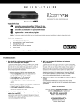
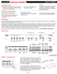
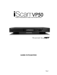
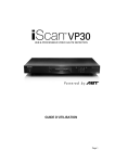
•
•
•
•
•
•
•
•
If any items are missing or damaged, please notify your dealer immediately.
iScan VP50 Video Processor
Universal 6V@7A AC-to-DC Power Converter
US IEC Power Cord (International Customers, consult your local authorized DVDO reseller)
Remote Control
iScan VP50 Owner’s Manual
Serial Cable for Software Updates and Automation (1:1)
VRS Optimization & Evaluation DVD
DVDO Software CD
Check the components
Notice: The information contained on this Quick Start card, including but not limited to any product specifications, is subject to change without notice.
å
ç
w
Register online at www.dvdo.com/register
Review the documentation for important information.
Remove the components and iScan VP50 from the box. Save the packing materials in case you need them later.
Unpack the box
HI GH-DEFI NI TI ON VI DEO PROCESS OR & H UB
Q U I C K
S T A R T
G U I D E
Troubleshooting
1. What should I do if the front panel display (FPD) of my iScan VP50 is showing an error message?
3. Why is the blue Status LED blinking on the front panel of my iScan VP50?
If the iScan VP50 does not boot correctly, you may get an error message.
Performing a factory default hard reset of the iScan should reboot the unit to its factory default (480p digital RGB 4:4:4 out). If a Factory Default does not correct the issue, a Hard Reset of the iScan should clear any memory errors and reboot the unit to its factory default (480p digital RGB 4:4:4 out). If you still get an error message after performing a hard reset, contact our
Technical Support department for assistance.
a. Performing a factory default of the iScan using the remote control:
• Press the Configuration button on the remote control until the FPD reads ‘Configuration / Factory Default’
• Press the Enter button. The FPD will read ‘No’
• Press the
p button. The FPD will read ‘Yes’
• Press the Enter button. The iScan will reboot to its factory default.
The Status LED on the iScan VP50 will blink blue if the iScan is processing an
HDCP protected signal on its HDMI inputs and it is unable to authenticate with
the display. Verify that your display is HDCP-compliant. If your display is not
HDCP-compliant then you will need to use the component connections from
your source and from your iScan to your display. If your display is HDCPcompliant, then verify that the ‘HDCP Mode’ is set to ‘On’ in the ‘Input Adjust’
and ‘Output Setup’ menus. If the problem persists, check your cabling and
try new cables, if possible, or try cycling the power on your display or HDCP
source to force reauthentication between your display and source.
4. Will I lose the settings on my iScan VP50 if I update the software version?
Currently, the iScan VP50 may lose its settings when a major software
update is performed. Please take note of your output settings before updating
your software.
b. Performing a hard reset of the iScan using the buttons on the front panel:
Setup Questions?
• Unplug the power from the back of the iScan
• Press the Menu and Exit buttons simultaneously while plugging the Check our website at www.dvdo.com/setup or contact
power back into the iScan.
us directly at [email protected] or by phone at:
2. What should I do if the picture is green when I use the analog output of my iScan VP50?
866.423.3836, extension 333
(Monday - Friday, 9 am to 5 pm PST)
A green picture usually means that a component video signal is being sent
to the RGBHV input of a display. Follow the instructions to set up your iScan
to work with a display with an RGBHV input.
DVDO Home Theater Products
by Anchor Bay Technologies, Inc.
300 Orchard City Drive, MS 131
Campbell, California 95008
Front and Back Panel
Status LED
IR Window
Front Panel Display (FPD)
Navigation Keys
Up
Menu
Enter
Exit
EXIT
MENU
On/Standby
Left
Analog Video
Input
SDI Input
OUTPUT
I
N
P
U
T
INPUT
1
2
3
4
H DM I
HDMI Output
Y (G)
O
U
T
P
U
T
HDMI Inputs
1, 2, 3, 4
SDI Input
(Optional)
Quick Note
Pb (B)
Component 1
(YPbPr or RGB)
Sync 1
Pr (R)
H
V
Y (G)
DC In
ANALOG VIDEO
Analog Video
Output
RGBHV/Component
Input
I
Pb (B)
Down Right
Digital Audio
Digital
Composite Audio Out Inputs 1, 2 Analog Audio
S-Video 1 Video 1
Inputs L, R
(optical) (optical)
L
Pr (R)
1
1
1
1
P
U
T
S 2
2
2
2
POWER
SYNC
COMPONENT
Power
Sync 2
Component 2
(YPbPr or RGB)
Component/RGBS 1
OUTPUT
INPUT
3
S-VIDEO
VIDEO
R
2
1
On/Standby
ANALOG AUDIO INPUT
4
D I G I TA L A U D I O
SERIAL PORT
S-Video 2 Composite Digital
Digital Audio Serial Port
Video 2
Audio Out Optical
Inputs 3, 4
Optical
(coaxial) Digital
(coaxial)
Input Analog Audio
Digital
S-Video 1 Video 1
1&2
Input
Output
This Quick Start Guide has been created to assist you
inPbthe
first
step
of setting
up yourY (G)iScan
VP50
unit, which is accessing the iScan’s On Screen Display (OSD)
Y (G)
(B)
Pr (R)
H
V
Pb (B)
Pr (R)
on your screen.
L
I
N
P
U
T
SDI
INPUT
OUTPUT
INPUT
O
U
T
P
U
T
+6V @5A
I 1
N
P
U
T
S 2
1
1
1
OUTPUT
R
2
1
DC In
INPUT
ANALOG AUDIO INPUT
Accessing the iScan’s OSD is crucial, not only in allowing the user to navigate the menu system, but its presence lets the user know that the iScan is sending
a compatible signal to the display. If the OSD is not visible on the display’s screen by pressing one of the sub-menu buttons on the remote control, then the
Output Setup of the iScan must be configured to work with the input that is being used on the display. Following all of the steps provided should allow you to
HDMI Output
HDMI Inputs
RGBHV/Component
Power
Component/RGBS 2
S-Video 2 Video 2
Coaxial
Coaxial
Serial Port
see the OSD.
1–4
Output
Digital
Digital Input
1
2
3
4
H DM I
ANALOG VIDEO
POWER
2
SYNC
2
COMPONENT
S-VIDEO
3
2
VIDEO
4
D I G I TA L A U D I O
Output
SERIAL PORT
3&4
Front Panel Display (F
To best set up your iScan VP50 unit with your display, we recommend that you consult your iScan VP50 Product Guide – “Setting up an iScan Using the Internal
Test Patterns and the VRS Optimization and Evaluation DVD.
Instruction in bold apply to specific buttons on either the front panel or remote control of the iScan VP50. Instructions in italics (top line / bottom line) apply
to information that is displayed on the Front Panel Display (FPD).
STEP 1 - Powering Up
SDI Input
Attach the removable power cord to the external power supply. Plug the removable power cord in to a wall outlet or power conditioner, if applicable.
Plug the
On/Standby
small connector attached to the cable that comes out of the power supply into your
iScan
VP50.
Press the On/Standby button on the front panel of the iScan.
Y
PB
PR
R PR/CR G Y B PB/CB H/Cs
V
Your iScan VP50 should power on and display DVDO iScan VP50 — Powered by ABT on the FPD. The Status LED on your iScan VP50 will turn red verifying
that there are no active inputs detected.
SDI
INPUT
STEP 2 - Connecting the iScan VP50 in your system
OUTPUT
Displays with a Digital Input (HDMI or DVI-D)
1
INPUT
2
3
4
Y
HDMI
PB
PR
R PR/CR G Y
B PB/CB H/Cs
V
HDMI Output
DVI-D
HDMI Output
H DM I
YHDMIPBInputs
PR
1, 2, has
3, 4
HDMI is backwards compatible with DVI-D with the use of either a cable or adapter. Connect the iScan VP50’s HDMI output to your display. If your display
an HDMI input, use an HDMI-to-HDMI cable. If your display has a DVI-D input, use an HDMI-to-DVI cable or adapter. The default output
the iScan VP50 is
Analogon
Video
digital RGB 4:4:4 which is the DVI standard. Once connected, press the Menu button and you should
see the iScan’s OSD.
SDI Input
Input
Displays with an Analog Input (Component or RGBHV)
I
N
P
U
T
SDI
INPUT
Y
PB
PR
OUTPUT
R PR/CR G Y
B PB/CB H/Cs
V
1
2
INPUT
3
H DM I
Component Output RGBHV HDMI
Inputs
Component or RGBHV via 5 BNCs HDMI
via HD15
1, 2, 3, 4
4
O
U
T
P
U
T
Y (G)
Pb (B)
Pr (R)
H
Sync
V
DC In
+6V @5A
ANALOG VIDEO
Analog Video
RGBHV/Component
Output
Output
The analog output on the iScan VP50 uses professional BNC connections. If the component or RGBHV cables you are using to connect to your display use RCA
terminations, you will need RCA-to-BNC adapters.
NOTE: The iScan VP50 cannot output an analog signal from a DVI or HDMI source (with HDCP encryption) that is connected to the iScan VP50.
Press the Output Setup button on remote control one time. You should see Analog/Digital / HDMI (Digital) on the FPD. Press the Up button until you see
Analog/Digital / BNC (Analog) on the FPD. Press the Enter button to choose analog video output. Press the Menu button, if you are connected to a component
input on your display, you should see the OSD from your iScan VP50 on your display.
If you are using an RGBHV input on your display, you will need to also change the color space and sync type. To change the color space from component to RGB,
press the Output Setup button, followed by the Down button, until the FPD reads Output Setup / Color Space. Press the Enter button to enter this submenu,
and then press the down button until the FPD reads Color Space / RGB. Press the Enter button to confirm this setting. Press the Menu button to see if the
iScan’s OSD is displayed. If it is not displayed, press the Output Setup button followed by the Down button until the FPD reads Output Setup / Sync Type.
Press the Enter button to enter this submenu and change the setting so that the FPD reads Sync Type / HV. Press the Enter button to confirm this setting.
I 1
N
P
U
T
S 2
POWER
SYN
Power
Sync
•
•
•
•
•
•
•
•
•
If any items are missing or damaged, please notify your dealer immediately.
iScan VP50 Video Processor
Universal 6V@7A AC-to-DC Power Converter
US IEC Power Cord (International Customers, consult your local authorized DVDO reseller)
Remote Control
iScan VP50 Owner’s Manual
Serial Cable for Software Updates and Automation (1:1)
VRS Optimization & Evaluation DVD
DVDO Software CD
Rack Mount Kit
Check the components
Notice: The information contained on this Quick Start card, including but not limited to any product specifications, is subject to change without notice.
å
ç
w
Register online at www.dvdo.com/register
Review the documentation for important information.
Remove the components and iScan VP50 from the box. Save the packing materials in case you need them later.
Unpack the box
HIGH-DEFINITION VIDEO PROCESSO R & H U B
Q U I C K
S T A R T
G U I D E
Troubleshooting
1. What should I do if the front panel display (FPD) of my iScan VP50 is showing an error message?
If the iScan VP50 does not boot correctly, you may get an error message.
Performing a factory default hard reset of the iScan should reboot the unit to its factory default (480p digital RGB 4:4:4 out). If a Factory Default does not correct the issue, a Hard Reset of the iScan should clear any memory errors and reboot the unit to its factory default (480p digital RGB 4:4:4 out). If you still get an error message after performing a hard reset, contact our
Technical Support department for assistance.
a. Performing a factory default of the iScan using the remote control:
• Press the Configuration button on the remote control until the FPD reads ‘Configuration / Factory Default’
• Press the Enter button. The FPD will read ‘No’
• Press the
p button. The FPD will read ‘Yes’
• Press the Enter button. The iScan will reboot to its factory default.
b. Performing a hard reset of the iScan using the buttons on the front panel:
• Unplug the power from the back of the iScan
• Press the Menu and Exit buttons simultaneously while plugging the power back into the iScan.
2. What should I do if the picture is green when I use the analog output of my iScan VP50?
A green picture usually means that a component video signal is being sent
to the RGBHV input of a display. Follow the instructions to set up your iScan
to work with a display with an RGBHV input.
3. Why is the blue Status LED blinking on the front panel of my iScan VP50?
The Status LED on the iScan VP50 will blink blue if the iScan is processing an
HDCP protected signal on its HDMI inputs and it is unable to authenticate with
the display. Verify that your display is HDCP-compliant. If your display is not
HDCP-compliant then you will need to use the component connections from
your source and from your iScan to your display. If your display is HDCPcompliant, then verify that the ‘HDCP Mode’ is set to ‘On’ in the ‘Input Adjust’
and ‘Output Setup’ menus. If the problem persists, check your cabling and
try new cables, if possible, or try cycling the power on your display or HDCP
source to force reauthentication between your display and source.
4. Will I lose the settings on my iScan VP50 if I update the software version?
Currently, the iScan VP50 may lose its settings when a major software
update is performed. Please take note of your output settings before updating
your software.
Setup Questions?
Check our website at www.dvdo.com/setup or contact
us directly at [email protected] or by phone at:
866.423.3836, extension 333
(Monday - Friday, 9 am to 5 pm PST)
DVDO Home Theater Products
by Anchor Bay Technologies, Inc.
300 Orchard City Drive, MS 131
Campbell, California 95008