1
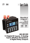
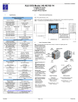
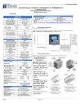
p/n 8593R1-ZXTx-RM-2011qsg Choose the drivers manually from the CD or the location Quick Start Guide where Zlinx™ Manager Software is installed. When the driver is installed a new COM port labeled “Xtreme” will show up in Windows Device Manager. Zlinx™ Xtreme Modem ZXTxx-RM 1 4 Check for All Required Hardware Connect the power supply to the PWR IN +/- terminals on the terminal block. Zlinx™ Xtreme Modem (one of the following models): o ZXT24-RM o ZXT9-RM This Quick Start Guide CD with Zlinx™ Manager Software and manual Antenna Mounting ears and hardware Additional items required but not included: o 10 – 30 VDC Power Supply o USB Cable Conduit mounting accessories sold separately, model ZXT-MT o Cable Gland o Conduit Accessories Power Connection, TB, & Antenna Connect the supplied antenna to the RPSMA connector. Figure 3. Communication Parameters Screen Operating Voltage – 10 to 30 VDC Maximum Surrounding Ambient Air Temperature - 74°C See Section 10. 5 Start Zlinx™ Manager Software Click the Connect button. If the modem is not found, the Auto Search button can be used to locate the modem. The auto search will use a sequence of COM Ports and settings until the response is received. If there is still no response, double check the power supply and USB cable. Also, make sure that no other devices are attached wired or wirelessly. Start the Zlinx™ Manager Software. 2 Install Zlinx™ Manager Software Insert the CD into your CD ROM Drive. The Zlinx™ Manager Install Wizard should start. Follow the on-screen instructions to install the software. If auto run is disabled, locate the ZlinxMgr.exe file on the CD-ROM drive and double click to launch it. The Install Wizard should start. Follow the on-screen instructions. 3 Click on the Radio Modem link. Click the Radio Modem Configuration link. o Select correct COM port and configure it for 9600 baud, Data Bits: 8, Parity: None, Stop Bit: 1. Figure 4. Radio Modem Not Found Screen Install USB Drivers Connect the device to the USB port on your PC. The “Found New Hardware Wizard” will guide you through the installation process. When prompted to connect to Windows Updates to search for drivers, select “No, not at this time” and follow the instructions for installing from the CD or the location on the hard drive. When the software locates the Radio Modem and you click the OK button, the Basic Modem Settings screen will be displayed. Corporate Headquarters: +1 815 433 5100 www.bb-elec.com European Headquarters: +353 91 792444 www.bb-europe.com p/n 8593R1-ZXTx-RM-2011qsg 6 On the Radio Modem that is NOT set up for Loopback Setup the Radio Modem Mode, run the RSSI Range Test. Observe the following indications: o The RD, TD and RSSI LEDs will flash as data is sent between the two units. o Test results will be displayed on the RSSI Range Test screen. Select a unique Network Identifier. This is especially Figure 5. Radio Modem Found Screen The Basic Modem Settings screen will display the Model Number, Function Set Type, Firmware Version, Channel Number, Network Identifier, Destination Address and Baud Rate. 7 important if you have other units operating in the same area. Set the Destination Address to FFFF (broadcast) (for ZXT9-RM connecting to Xtreme I/O). If desired, you can change the baud rate and parity on the Basic Modem Settings screen. Remember to change your COM port to match. Click the Update button to store the settings. Click the Advanced Modem Settings tab. Check the Power Level (PL). Select the appropriate power level for your application. For bench testing, PL should be set to 0 and Radio Modems should be separated by at least 1 meter. When using higher power levels, separate the modems by at least 7 meters. If you changed any settings, store them by clicking the Update button. 9 Configure and Wire to Match Serial Devices Configure serial settings on the Basic Modem Settings tab to match your serial device. Configure the DIP Switch to match your serial device. Set up Your Second Radio Modem Click the Exit button. Power off the Radio Modem. Configure your second Radio Modem using the same procedure. Do not proceed to the RSSI Range Test step until you have a second modem configured. Two properly configured units are required to proceed to the next step. Configure the second unit with the same settings. 8 Figure 6. Basic Modem Settings Screen RSSI Range Test Set the remote modem to Loopback Mode. Loopback connections can be made using the RS-422/485 interface by setting switch 1 and 2 to ON and 3 and 4 to OFF (internal loopback with echo on). Wiring examples are located in the manual. See Step 4 for TB layout. Terminal Block Signal Direction: RS-232 (Modem is a DCE Device) TD – Input, RD – Output, RTS – Input, CTS – Output. o RS-422/485 Four Wire TDA(-)/TDB(+) – Output, RDA(-)/RDB(+) - Input o RS-485 2-Wire - The A(-) and B(+) Signals are tied together by the DIP Switch and are bi-directional. You are now ready for field installation o Corporate Headquarters: +1 815 433 5100 www.bb-elec.com European Headquarters: +353 91 792444 www.bb-europe.com 10 Information – UL class 1 Division 2 Operating Voltage – 10 to 30 VDC WARNING- SUITABLE FOR USE IN CLASS I, DIVISION 2, GROUPS A, B, C AND D HAZARDOUS LOCATIONS, OR NONHAZARDOUS LOCATIONS ONLY. The low-voltage (LV) wiring – DC power, analog & digital signals – must be separated from the high voltage (HV) wiring for the relay contacts. In all cases HV wiring must be rated minimum 250V. Separation between circuits can be accomplished by using one of the three following methods: a. Use one conduit knockout to route LV wiring and the second conduit knockout to route the HV wiring, OR see methods 2 and 3 below. WARNING - EXPLOSION HAZARD - SUBSTITUTION OF ANY COMPONENT MAY IMPAIR SUITABILITY FOR CLASS I, DIVISION 2. WARNING – EXPLOSION HAZARD – WHEN IN HAZARDOUS LOCATIONS, TURN OFF POWER BEFORE REPLACING ANTENNA. Intended use of equipment – please see the B&B Electronics Data Sheets and Quick Start Guides for each Zlinx Xtreme product for explanations of the intended use of this equipment. Wiring Terminals – Use Copper Wire Only, one conductor per terminal Wire Range 30 – 12 AWG Maximum Surrounding Ambient Air Temperature - 74°C UL Class I, Division 2 wiring methods. The Zlinx Xtreme enclosure is provided with two conduit knockouts that serve as wiring provisions for Class I, Division 2 wiring methods per the National Electrical Code (NEC). b. c. The remaining two methods use one conduit knockout for all wiring. In this case a UL Recognized (UL type QCRV2) conduit plug must be used per the NEC to plug the second conduit knockout. Enclose LV wiring in a 250V rated insulated sheath to separate it from the HV wiring, OR Use 250vac rated wires for both LV and HV wiring. p/n 8593R1-ZXTx-RM-2011qsg Sealed Relay Device Information: Sealed Device: Relay Models G6RL-14-ASI-DC5, G6RL-14-ASI-DC6, G6RL-14-SR-ASI-DC5 or G6RL-14SR-ASI-DC6 manufactured by Omron Corp. Relay Case and Base Sealant Manufacturer Mitsubishi Engineering Plastics Corp. Three Bond Ltd. Type 5010GN6-30M8AM TB2225G Temperature rating of field installed conductors - Field conductors shall be rated 60C/75C minimum (either are acceptable) and sized accordingly. When conduit openings are not being used, a UL Recognized plug (type QCRV2) shall be used. The following is UL-required information regarding the Sealed Relay Devices: WARNING – Exposure to some chemicals may degrade the sealing properties of materials used in the Sealed Relay Device. RECOMMENDATION – It is recommended to inspect the sealed relay device periodically and to check for any degradation of the materials and to replace the component product, not the sealed device, if any degradation is found. The following instructions include procedures to be followed in order to ensure UL "separation between circuits" as defined in the NEC. Corporate Headquarters: +1 815 433 5100 www.bb-elec.com European Headquarters: +353 91 792444 www.bb-europe.com