1
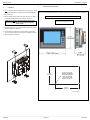
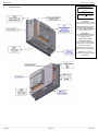
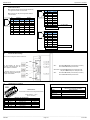
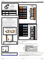
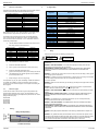
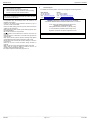
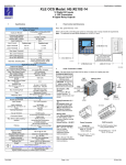
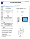
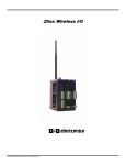
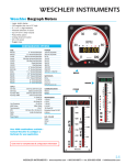
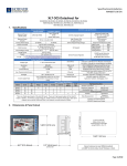
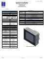
MAN0902-01-EN
Specifications / Installation
XL6/XL6e OCS Models
HE-XL102–14 / HE-XL1E2–14
12 Digital DC Inputs
4 10k Thermistors
6 Digital Relay Outputs
1
Specifications
Specifications
Digital DC Inputs
12 including 4 configurable
Inputs per Module
HSC inputs
Commons per Module
1
Input Voltage Range
12 VDC / 24 VDC
Absolute Max. Voltage
35 VDC Max.
Input Impedance
10 kΩ
Input Current
Positive Logic
Negative Logic
Upper Threshold
0.8 mA
-1.6 mA
Lower Threshold
0.3 mA
-2.1 mA
Max Upper Threshold
8 VDC
Min Lower Threshold
3 VDC
OFF to ON Response
ON to OFF Response
1 ms
1 ms
10 kHz Totalizer/Pulse,
Edges
HSC Max. Switching Rate
5 kHz Frequency/Pulse,
Width
2.5 kHz Quadrature
Digital Relay Outputs
Outputs per Module
6 relay
Commons per Module
6
Max. Output Current per Relay
3 A at 250 VAC, resistive
Max. Total Output Current
5 A continuous
Max. Output Voltage
275 VAC , 30 VDC
Max. Switched Power
1250 VA, 150 W
Contact Isolation to XL6
1000 VAC
ground
Max. Voltage Drop at Rated
0.5 V
Current
Expected Life
No load: 5,000,000
(See Derating section for
Rated load: 100,000
chart.)
300 CPM at no load
Max. Switching Rate
20 CPM at rated load
Type
Mechanical Contact
One update per ladder scan
Response Time
plus 10 ms
Thermistor Inputs, Medium Resolution
Number of Channels
4
Input Ranges
10K OHMThermistor
Input Impedance
(Clamped @ -0.5 VDC to 12
VDC)
Nominal Resolution
Half Bridge
9.59K ohm pulled up to
4.8 VDC
10 Bits
%AI at 10K Ohm
15,008 counts
All channels converted once
per ladder scan
±0.5°F or ±0.3°C
Using specified linearization
in ladder program
160 Hz hash (noise) filter
1-128 scan digital running
average filter
Conversion Speed
Max. Error at 25°C reading /
ambient
Filtering
General Specifications
Required Power
(Steady State)
Required Power
(Inrush)
Primary Power Range
Relative Humidity
500 mA @ 24 VDC
Clock Accuracy
Operating Temperature
Terminal Type
Weight
CE
UL
Serial Ports
Ethernet
USB
Removable Media
Smartstix
30 A for 1 ms @ 24 VDC – DC Switched
2.5 A for 4 ms @ 24 VDC - AC Switched
10 – 30 VDC
5 to 95% Non-condensing
+/- 35 ppm maximum at 25° C
(+/- 1.53 Minutes per Month)
-10°C to +60°C
Screw Type, 5 mm Removable
26.5 oz. (.751 kg)
See Compliance Table at
http://www.heapg.com/Pages/TechSupport/ProductCert.html
Connectivity
2 Serial Ports – RS232 & RS485
10/100-Mbps (XL6e models only)
USB Networking Port for communication with PCs and programming Port
Removable Media for upto 2 GB of storage for programs, data logging or
screen capture
Remote IO modules communicating on CAN
Note: Highest usable frequency for PWM output is 65 KHz
HE-XL102-14/HE-XL1E2-14
__________________________________________________________________________________________________________________________________________________________________
3/26/2009
Page 1 of 7
ECN # 956
MAN0902-01-EN
2
Specifications / Installation
3
Installation
1. Prior to mounting, observe requirements for the panel layout design
and spacing/clearances in the OCS XL6 Series Manual (MAN0883).
Panel Cut-Out and Dimensions
Refer to the XL6 User Manual (MAN0883) for panel box information and a handy checklist of requirements.
2. Cut the host panel.
3. Insert the OCS through the panel cutout (from the front). The gasket
material needs to be between the host panel and the OCS.
Note: The tolerance to meet NEMA standards is ± 0.005” (0.1 mm).
Caution: Do not force the OCS into the panel cutout.
An incorrectly sized panel cutout can damage the
touch screen.
Note: Max. panel thickness: 5 mm
4. Install and tighten the mounting clips (provided with the OCS) until the
gasket material forms a tight seal.
5. Connect cables as needed such as communications, programming,
power and CsCAN cables to the ports using the provided connectors.
6.
Begin configuration procedures.
5.156”
[131mm]
001XLQX007
R .125” [3 mm] TYP.
RADIUS CORNERS
WHEN REQUIRING
DUST OR WATER
TIGHT SEAL PER
NEMA 4, 4X OR 12
6.875”
[175mm]
001OCS003-R1
__________________________________________________________________________________________________________________________________________________________________
3/26/2009
Page 2 of 7
ECN # 956
MAN0902-01-EN
4
Ports and Connectors
Specifications / Installation
To Remove I/O Cover:
Unscrew 4 screws located on the
cover.
Remove cover.
CAUTION: Do not over tighten
screws when replacing the back
cover.
I/O Jumpers:
I/O Jumpers (JP) are located internally.
To access, remove I/O cover of unit.
Wiring Connectors (J1 / J2) and
I/O Jumpers (JP1 and JP2) are
described in the Wiring and Jumpers
section of this document.
Memory Slot:
Uses Removable Memory for data
logging, screen captures, program
loading and recipes.
Horner Part No.: HE-MC1
Serial Communications:
MJ1: (RS-232 / RS-485) Used for
Cscape programming and ApplicationDefined Communications.
MJ2: (RS-232 / RS-485) Used for
Application-Defined Communications.
Ethernet: Used for Cscape
programming and Application-Defined
Communications.
__________________________________________________________________________________________________________________________________________________________________
3/26/2009
Page 3 of 7
ECN # 956
MAN0902-01-EN
4.1
Specifications / Installation
MJ2 Pinouts in Half and Full Duplex Modes
Serial Communications:
MJ1: (RS-232 / RS-485) Use for Cscape programming
and Application-Defined Communications.
Pin
8
MJ2: (RS-232 / RS-485) Use for Application-Defined
Communications.
1
Pin
8
1
MJ1 Pins
MJ2 Pins
Signal
Direction
Signal
Direction
8
TXD
7
6
RXD
0V
OUT
TXD
OUT
IN
Ground
RXD
0V
IN
Ground
5*
+5 60mA
OUT
+5 60mA
OUT
4
RTS
OUT
TX-
OUT
3
CTS
IN
TX+
OUT
2
1
RX- / TXRX+ / TX+
IN / OUT
IN / OUT
RXRX+
IN
IN
MJ2 Pins
Signal
Direction
8
TXD
OUT
7
6
RXD
IN
0V
Ground
5*
+5 60mA
OUT
4
TX-
OUT
3
TX+
OUT
2
1
TX-/RXTX+/RX+
IN/OUT
IN/OUT
* +5V 60mA Max
MJ2 Half Duplex Mode
Pin
0
-
1
MJ2 Pins
Signal
Direction
8
TXD
OUT
7
6
RXD
0V
IN
Ground
5*
+5 60mA
OUT
4
TX-
OUT
3
TX+
OUT
2
1
RXRX+
IN
IN
* +5V 60mA Max
MJ2 Full Duplex Mode
4.2
External DIP Switch Settings
As seen when looking at the side of the XL6 unit :
MJ1
On
The DIP Switches are used for
termination of the RS-485 ports. The
XL6 is shipped un-terminated.
To terminate, select one of the DIP
Switches and configure it based upon
the option that is desired.
Off
SW1 -
ON enables MJ2 RS485 port termination (121 Ohms).
OFF disables MJ2 RS485 port termination.
On
Off
SW2 & SW3 - ON places MJ2 RS485 port in half-duplex mode.
OFF places MJ2 RS485 port in full-duplex mode.
On
SW4 -
ON enables MJ1 RS485 port termination (121 Ohms).
OFF disables MJ1 RS485 port termination.
Off
MJ2
4.3
CAN Network Port and Wiring
4.4
Ethernet Port
Speeds
CAN Connector
Use the CAN Connector when using CsCAN network.
Torque rating 4.5 – 7 Lb-In
(0.50 – 0.78 N-m)
Pin
1
2
3
4
5
Signal
VCN_L
SHLD
CN_H
NC
NET1 Port Pin Assignments
Signal Description
CAN Ground
CAN Data Low
Shield Ground
CAN Data High
No Connect
Modes
Auto-Negotiation
Connector Type
Cable Type
(Recommended)
Port
10 BaseT Ethernet (10-Mbps)
100 BaseTx Fast Ethernet (100-Mbps)
Half or Full Duplex
Both 10/100-Mbps and Half/Full Duplex
Shielded RJ-45
CAT5 (or better) UTP
Auto MDI/MDI-X
Direction
−
In/Out
−
In/Out
−
__________________________________________________________________________________________________________________________________________________________________
3/26/2009
Page 4 of 7
ECN # 956
MAN0902-01-EN
4.5
Specifications / Installation
5.2
Power Port and Wiring
Wiring Examples
Power Connector
J1 Orange
Positive Logic In
Digital In /
Analog In
Power Up:
Connect to Earth Ground.
Apply 10 - 30 VDC.
Screen lights up.
J1 Orange
Terminal
Connector
I1
I2
I3
I4
I5
I6
I7
I8
H1
0V
A1
A2
A3
A4
0V
Torque rating 4.5 – 7 Lb-In
(0.50 – 0.78 N-m)
Primary Power Port Pins
Signal
Description
Pin
1
Ground
Frame Ground
2
V-
Input Power Supply Ground
3
V+
Input Power Supply Voltage
5
Wiring and Jumpers
Wire according to the type of inputs / outputs used, and select the
appropriate jumper option.
Name
I1
IN1
IN2
IN3
IN4
IN5
IN6
IN7
IN8
HSC1 /IN9
Ground
Thermistor 1
Thermistor 2
Thermistor 3
Thermistor 4
Ground
I2
I3
I4
I5
12-24VDC
I6
I7
I8
H1
0V
T
A1
A2
T
T
A3
T
A4
0V
001XLE067
Wiring Specifications
For I/O wiring (discrete), use the following wire type or
equivalent: Belden 9918, 18 AWG (0.8 mm2) or larger.
For shielded Analog I/O wiring, use the following wire type or
equivalent: Belden 8441, 18 AWG (0.8 mm2) or larger.
J2 Black
Terminal
Connector
C6
R6
C5
R5
C4
R4
C3
R3
C2
R2
C1
R1
H4
H3
H2
For CAN wiring, use the following wire type or equivalent:
Belden 3084, 24 AWG (0.2 mm2) or larger.
Use copper conductors in field wiring only, 60/75° C
Positive Logic vs. Negative Logic Wiring
The XL6 HEXL102 can be wired for Positive Logic
inputs or Negative Logic inputs.
I1
I1
12-24VDC
0V
0V
001XLE036
Positive Logic In
Negative Logic In
J2 Black
Positive Logic
Digital In / Relay Out
Name
Relay 6 COM
Relay 6 NO
Relay 5 COM
Relay 5 NO
Relay 4 COM
Relay 4 NO
Relay 3 COM
Relay 3 NO
Relay 2 COM
Relay 2 NO
Relay 1 COM
Relay 1 NO
HSC4 / IN12
HSC3 / IN11
HSC2 / IN10
230VAC
OR
25VDC
C6
N
L
230VAC
OR
25VDC
R6
LOAD
C5
N
L
230VAC
OR
25VDC
R5
LOAD
C4
N
L
230VAC
OR
25VDC
R4
LOAD
C3
N
L
230VAC
OR
25VDC
R3
LOAD
C2
N
L
230VAC
OR
25VDC
R2
LOAD
C1
N
L
R1
LOAD
H4
J1
H3
12-24VDC
J2
JP2
H2
0V ON J1
001XLE015
JP1
001XLE025
Location of I/O jumpers (JP2 and JP1) and wiring
connectors
(J1 and J2).
6
Analog Conditioning
6.1
Filter
Filter Constant sets the level of digital filtering according to the following chart.
I/O Jumpers Settings (JP1)
Default
Note:
The Cscape Module Setup configuration must match the selected
I/O (JP) jumper settings.
]
JP1 Digital DC In / HSC
Positive Negative
Logic
Logic
0
%Complete [
5.1
1
2
3
4
5
6
Filter
Constant
7
100
90
80
70
60
50
40
30
20
10
0
0
20
40
60
80
100
Scans
Digital Filtering. The illustration above demonstrates the effect of digital filtering (set with Filter Constant)
on module response to a temperature change.
It is recommended that the filter constant for the HE-XL102-14/HE-XL1E2-14 be set to a value of 7. This
will minimize noise and jitter, improve effective resolution, and provide adequate speed for most
temperature monitor and control applications.
__________________________________________________________________________________________________________________________________________________________________
3/26/2009
Page 5 of 7
ECN # 956
MAN0902-01-EN
6.2
Specifications / Installation
Thermistor Linearization
8
I/O Register Map
Thermistors are measured using a half-bridge circuit that exhibits variable
resolution and the associated increased measurement range.
Temperature, degrees C
-55
-35
-15
5
25
45
65
85
105
125
145
Resolution, degrees C
1.05
0.36
0.17
0.11
0.1
0.13
0.22
0.30
0.55
0.85
1.35
Degrees F
-3.50017e-028
4.32483e-023
-2.23381e-018
6.23979e-014
-1.02493e-009
1.01226e-005
-0.0635617
326.981
%Q21 to %Q32
%AI1 to %AI4
%AI5, %AI6
%AI7, %AI8
%AI9, %AI10
%AI11, %AI12
Warning: Electrical
Shock Hazard.
Warning: Consult
user documentation.
This equipment is suitable for use in Class I, Division 2, Groups A, B, C and D or Non-hazardous
locations only
3)
Perform the Real Math Expression
4)
%R3 = (((%R11*%R1+%R13)*%R1+%R15)*%R1+%R17)
5)
Perform the Real Math Expression %R5 =
(((%R3*%R1+%R19)*%R1+%R21)*%R1+%R23)*%R1+%R25
6)
Load %R0005 result into another register such as %R0007 to
save the temperature value.
7)
Steps 2 though 5 can be on a single rung.
The expression rung may be copied, substituting %AI0002 and %R00011
for %AI0001 and %R0007, and used to linearize the second channel.
Contact Horner APG Technical Support for an example file containing the
above program.
WARNING – EXPLOSION HAZARD – Do not disconnect equipment unless power has been
switched off or the area is known to be non-hazardous.
AVERTISSEMENT - RISQUE D'EXPLOSION - AVANT DE DECONNECTOR L'EQUIPMENT,
COUPER LE COURANT OU S'ASSURER QUE L'EMPLACEMENT EST DESIGNE NON
DANGEREUX.
WARNING: To avoid the risk of electric shock or burns, always connect the safety (or earth) ground
before making any other connections.
WARNING: To reduce the risk of fire, electrical shock, or physical injury it is strongly recommended
to fuse the voltage measurement inputs. Be sure to locate fuses as close to
the source as possible.
WARNING: Replace fuse with the same type and rating to provide protection against risk of fire and
shock hazards.
WARNING: In the event of repeated failure, do not replace the fuse again as a repeated failure
indicates a defective condition that will not clear by replacing the fuse.
Thermistor Types
The HE-XL102-14/HE-XL1E2-14 with the given example ladder code
supports Kele Engineering Precon Type III, 10 KΩ thermistors. It also
directly supports the following 10 KΩ (Beta=3574) thermistors from Yellow
Springs Instruments (YSI).
44006 46006
44106 46031
44406 46041
44031 44907
45006 44908
7
Safety
When found on the product, the following symbols specify:
Load %AI0001 into %R0001 as a Real.
WARNING – EXPLOSION HAZARD – Substitution of components may impair suitability for Class I,
Division 2.
AVERTISSEMENT - RISQUE D'EXPLOSION - LA SUBSTITUTION DE COMPOSANTS PEUT
RENDRE CE MATERIAL INACCEPTABLE POUR LES EMPLACEMENTS DE CLASSE 1,
DIVISION 2.
WARNING - The USB parts are for operational maintenance only. Do not leave permanently
connected unless area is known to be non-hazardous.
WARNING – EXPLOSION HAZARD - BATTERIES MUST ONLY BE CHANGED IN AN AREA
KNOWN TO BE NON-HAZARDOUS
AVERTISSEMENT - RISQUE D'EXPLOSION - AFIN D'EVITER TOUT RISQUE D'EXPLOSION,
S'ASSURER QUE L'EMPLACEMENT EST DESIGNE NON DANGEREUX AVANT DE CHANGER
LA BATTERIE.
Derating
WARNING - Battery May Explode If Mistreated. Do Not Recharge, Disassemble or Dispose Of In
Fire.
Relay Life Expectancy
Operation
(x104)
%AQ1, %AQ2
PWM1 Duty Cycle
%AQ3, %AQ4
PWM2 Duty Cycle
%AQ5, %AQ6
PWM Prescale
%AQ7, %AQ8
PWM Period
%AQ9 to %AQ14
Analog outputs
Note: Not all XL6 units contain the I/O listed in this table.
9
2)
6.3
Digital Inputs
Output Fault
Reserved
Digital outputs
Clear HSC1 accumulator to 0
Totalizer: Clear HSC2
Quadrature 1-2: Accumulator 1 Reset to max – 1
Clear HSC3 Accumulator to 0
Totalizer: Clear HSC4
Quadrature 3-4: Accumulator 3 Reset to max – 1
Reserved
Analog inputs
HSC1 Accumulator
HSC2 Accumulator
HSC3 Accumulator
HSC4 Accumulator
%Q20
Load the desired linearization coefficients into a table on First
Scan using a Move Constant Data block.
Degrees C
-1.94454e-028
2.40268e-023
-1.24101e-018
3.46655e-014
-5.69403e-010
5.62368e-006
-0.0353121
163.878
%I1 to %I24
%I32
%I25 to %I31
%Q1 to %Q16
%Q17
%Q19
Linearization must be performed by the user in the ladder application
code, using 26 internal %R registers per channel. The example below
uses %R1-26 to linearize one channel - %AI1. Linearization consists of
the following example steps.
Registers (Real)
R0011
R0013
R0015
R0017
R0019
R0021
R0023
R0025
Description
%Q18
Best resolution is at 25°C, 77°F. With a constant 0.1°C resolution circuit,
the measurement range would only extend from –26°C to +76°C.
1)
Registers
40
30
20
10
0
WARNING: Only qualified electrical personnel familiar with the construction and operation of this
equipment and the hazards involved should install, adjust, operate, or service this equipment. Read
and understand this manual and other applicable manuals in their entirety before proceeding.
Failure to observe this precaution could result in severe bodily injury or loss of life.
1
2
3
4
Contact Current (A)
__________________________________________________________________________________________________________________________________________________________________
3/26/2009
Page 6 of 7
ECN # 956
MAN0902-01-EN
This device complies with part 15 of the FCC Rules. Operation is
subject to the following two conditions:
1. This device may not cause harmful interference.
2. This device must accept any interference received, including
interference that may cause undesired operation.
Radiated Emission Compliance: For compliance requirement, a
ferrite (Horner P/N FBD006 supplied with the unit) needs to be placed
on the AC/DC line with one loop.
All applicable codes and standards need to be followed in the
installation of this product.
Adhere to the following safety precautions whenever any type of
connection is made to the module:
Connect the safety (earth) ground on the power connector first before
making any other connections.
When connecting to electric circuits or pulse-initiating equipment, open
their related breakers.
Do not make connections to live power lines.
Make connections to the module first; then connect to the circuit to be
monitored.
Route power wires in a safe manner in accordance with good practice
and local codes.
Wear proper personal protective equipment including safety glasses
and insulated gloves when making connections to power circuits.
Ensure hands, shoes, and floors are dry before making any connection
to a power line.
Make sure the unit is turned OFF before making connection to
terminals.
Make sure all circuits are de-energized before making connections.
Before each use, inspect all cables for breaks or cracks in the
insulation. Replace immediately if defective.
• Use Copper Conductors in Field Wiring Only, 60/75° C.
Specifications / Installation
10
Technical Support
For assistance and manual updates, contact Technical Support at the following locations:
North America:
Tel: 317 916-4274
Fax: 317 639-4279
Web: http://www.heapg.com
Email: [email protected]
Europe:
Tel: +353-21-4321266
Fax: +353-21-4321826
Web: http://www.horner-apg.com
Email: [email protected]
"WARNING: EXPOSURE TO SOME CHEMICALS MAY DEGRADE
THE SEALING PROPERTIES OF MATERIALS USED IN THE Tyco relay PCJ
Cover / case & base: Mitsubishi engineering Plastics Corp.
5010GN6-30 or 5010GN6-30 M8 (PBT)
Sealing Material: Kishimoto 4616-50K (I part epoxy resin)
It is recommended to periodically inspect the relay for any
degradation of properties and replace if degradation is found
No part of this publication may be reproduced without the prior agreement and written permission
of Horner APG, Inc. Information in this document is subject to change without notice.
__________________________________________________________________________________________________________________________________________________________________
3/26/2009
Page 7 of 7
ECN # 956