1
BMC Messaging Interfaces
QSSC-S4R Technical Product Specification
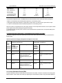
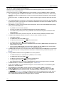
But, (per channel session limit) (bullet 4) > (total session slots) (bullet 3); this is done so that the available slots can
be used optimally. Even then, the user might not be able to open the Maximum # sessions per channel on a particular
channel. The Maximum per channel session limit is used only to maintain fairness in session usage across the
Channels. The GetSessionInfo() command will return the hard- coded (see bullet 3) value of the total MAX session
slots available.
The SetUserAccess() Command can be used to limit the number of concurrent sessions open per user. This user
configured value together with the internal hard- coded per channel session limits (bullet 4) might sometimes not
allow the usage of all session slots. Finally (bullet 5) further resource constraints might not allow the full utilization of
the session slots, in those cases the FW might dynamically reduce the number of slots available.
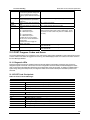
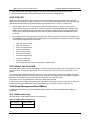
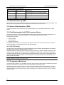
On QSSC-S4R platform, maximum no of IPMI over LAN sessions are configured as 16 (par LAN channel) and to
ensure web server availability, 4 session slots are reserved for Embedded Web Server. Total no of possible sessions
at any point of time are 36.
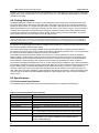
25.4 Media Bridging
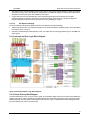
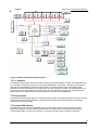
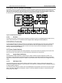
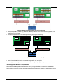
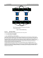
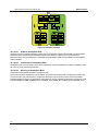
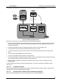
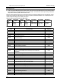
The BMC supports bridging between the LAN and IPMB interfaces. This allows the state of other intelligent controllers
in the chassis to be queried by remote console software. Requests may be directed to controllers on the IPMB, but
requests originating on the IPMB cannot be directed to the LAN interface unless the request is originated by the ME
on the secondary IPMB.
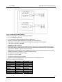
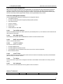
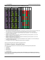
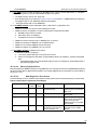
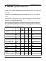
Available bridging combinations:
x
KCS to IPMB (Primary)
x
KCS to IPMB (Secondary)
x
LAN to IPMB (Primary)
x
LAN to IPMB (Secondary)
x
IPMB (Secondary) to LAN
25.5 Request / Response Protocol
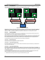
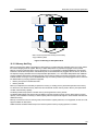
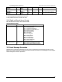
The protocols are request / response protocols. A request message is issued to an intelligent device. The intelligent
device responds with a response message. For example, with respect to the IPMB interface, both request messages
and response messages are transmitted on the bus using I2C master write transfers. An intelligent device acting as
an I2C master issues a request message. This is received by an intelligent device as an I2C slave. The corresponding
response message is issued from the responding intelligent device as an I2C master, and is received by the request
originator as an I2C slave.
25.6 Host to BMC Communication Interface
25.6.1 LPC / KCS Interface
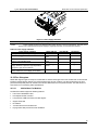
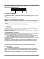
The BMC firmware supports two 8042 keyboard controller style (KCS) interface ports as described in the Intelligent
Platform Management Interface Specification Second Generation v2.0. These interfaces are mapped into the host I/O
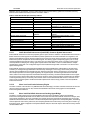
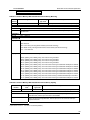
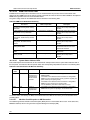
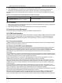
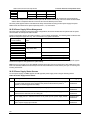
space and accessed via the chipset LPC bus. These interfaces are assigned with the following uses and addresses:
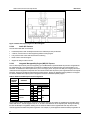
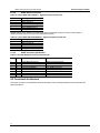
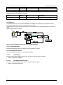
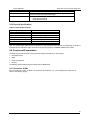
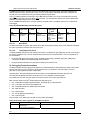
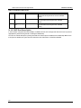
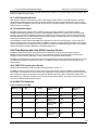
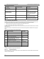
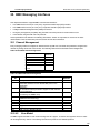
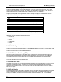
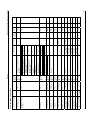
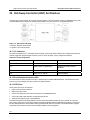
Table 195. Keyboard Controller Style Interfaces
Use
Address
SMS, BIOS POST, and utility 0CA2h –
access
0CA3h
SMM Interface SMI handling for error logging 0CA4h –
0CA5h
Name
SMS Interface
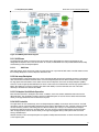
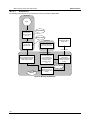
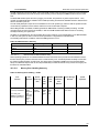
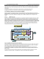
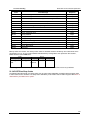
The BMC gives higher priority to transfers occurring through the server management mode (SMM) interface. This
provides minimum latency during SMI accesses. The BMC acts as a bridge between the server management
software (SMS) and the IPMB interfaces. Interface registers provide a mechanism for communications between the
BMC and the host system. Most platforms implement the interfaces as host I/O space mapped registers. The
interfaces consist of three sets of two 1-byte- wide registers.
288