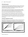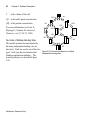
1
User’s Manual Model CSC 5300 Nano-Isothermal Titration Calorimeter III Isothermal Titration Calorimeter, User’s Manual Revision 40605 Copyright ©2005 Calorimetry Sciences Corporation All Rights Reserved Printed in the United States of America. No part of the manual may be photocopied or reproduced in any form without the express written permission of Calorimetry Sciences Corporation. This manual is supplied “as is” without any warranty of any kind, and is subject to change without notice. Calorimetry Sciences Corporation shall not be liable for any technical inaccuracies, typographical errors, editorial omissions, any direct, indirect, or consequential damages resulting from the use of information contained in this manual. Trademark Acknowledgements �� ���� ��� �� �� ������ IBM™ and Personal Computer are registered trademarks of International Business Machines Corp. Microsoft™ and Windows™, are trademarks of Microsoft Corporation. All other products are trademarks or registered trademarks of their respective companies. ������� Calorimetry Sciences Corp. 890 West 410 North, Suite A, Lindon, Utah 84042 USA www.calorimetrysciences.com CSC 5300 N-ITC III i Table of Contents CHAPTER ONE: SPECIFICATIONS AND WARRANTY . 1 Calorimeter Specifications ......................................................1 Warranty...................................................................................1 BindWorks Warranty ..............................................................2 License.......................................................................................3 Overview................................................................................3 Calorimetry Sciences Corporation Software License ............3 CHAPTER TWO: INSTALLATION ................................... 7 N-ITC III Operating Environment ........................................7 System Requirements.............................................................7 Space Requirements...............................................................7 Ambient Temperature Requirements .....................................7 Power Requirements ..............................................................7 N-ITC III Setup........................................................................8 Unpacking and Inspection......................................................8 N-ITC III Location.................................................................9 N-ITC III Connections...........................................................9 Computer Setup ...................................................................10 Powering the System............................................................10 User’s Manual ii Table of Contents Reinstalling Software...........................................................11 CHAPTER THREE: THEORY OF OPERATION ........... 13 Introduction to Isothermal Titration Calorimetry .............13 Applications ............................................................................14 Batch/Incremental Titration .................................................14 Titration/Data Analysis ........................................................16 Calculation of Equilibrium Constants..................................16 Mathematical Modeling.........................................................17 Introduction to Equilibrium Models ....................................17 Relating Heat, Enthalpy, and Binding Constants.................17 Fitting of Calorimetric Data .................................................21 CHAPTER FOUR: HARDWARE DESCRIPTION.......... 23 Description of Parts and Functions ......................................23 Measuring Unit ....................................................................23 Reaction Vessel ....................................................................24 Syringe/Stirrer......................................................................24 Burette Assembly .................................................................25 USB Connection ..................................................................28 Power Supply .......................................................................29 Cleaning Tool.......................................................................29 Calorimetry Sciences Corp. CSC 5300 N-ITC III iii CHAPTER FIVE: SOFTWARE DESCRIPTION ............ 33 Overview .................................................................................33 ITCRun Software Installation ..............................................33 General....................................................................................33 Main Menu .............................................................................34 File Menu .............................................................................34 View Menu...........................................................................35 Experiment Menu.................................................................35 Buret Menu ..........................................................................37 Help Menu ...........................................................................38 Feature Tabs ...........................................................................38 Setup Tab..............................................................................38 Monitor Tab..........................................................................40 Data Tab ...............................................................................41 System Tab and Diagnostics Tab .........................................42 Performing a Titration using ITCRun.................................42 BindWorks ..............................................................................45 Overview..............................................................................45 Getting Started .....................................................................46 Using BindWorks ...................................................................46 Manipulation of raw data .....................................................46 User’s Manual iv Table of Contents Integration of the peak .........................................................49 Modeling and Fit of the Data ...............................................50 Modeling .................................................................................51 Modeling Overview .............................................................51 Designing an Experiment ......................................................55 CHAPTER SIX: SAMPLE EXPERIMENTS ................... 59 Experiment Overview............................................................59 Experiment Walk-Through...................................................60 Introduction............................................................................60 Chemical Calibration.............................................................60 Heat of Protonation of Tris Base..........................................60 Sample Experiment................................................................63 Binding of 2’-CMP to RNase A...........................................63 CHAPTER SEVEN: TROUBLESHOOTING .................. 69 Minimizing Blank Corrections .............................................69 Operation Away from Ambient Temperature......................69 Stirring Speeds .......................................................................69 Calorimetry Sciences Corp. CSC 5300 N-ITC III 1 Chapter One: Specifications and Warranty Calorimeter Specifications CSC 5300 Nano-Isothermal Titration Calorimeter III Specifications Baseline stability ±0.02 μcal/sec/hr Response Time 15 seconds Injection interval 150 seconds minimum Cell volume 1.0 mL (24K Gold) Precision burette 100 or 250 μL Volume increment 1–15 μL Delivery precision ±0.01 μL Stirring rate 0 to 300 rpm Temperature Range 2 to 80°C Power requirements 95-250 Volts, 50-60 Hz. Table 1: CSC 5300 Isothermal Titration Calorimeter Specifications. Warranty Calorimetry Sciences Corporation warrants this product against defects in materials and workmanship for a period of two (2) years from the shipment date. Any product that proves defective during its stated warranty period will be repaired by Calorimetry Sciences Corporation. The foregoing warranty will not apply to defects resulting from: • Improper or inadequate maintenance, adjustment, calibration or operation by the buyer. User’s Manual 2 Chapter 1: Specifications and Warranty • Unauthorized modification or misuse. • Operation outside the electrical specifications for the product. • Improper site or buyer-induced contamination or leaks. • Failure to use proper surge protection. • Improper return packaging. To exercise this warranty, please call or write Calorimetry Sciences Corporation. BindWorks Warranty LIMITED WARRANTY. Calorimetry Sciences Corporation warrants that BindWorks will perform substantially in accordance with the accompanying printed materials for a period of ninety (90) days from the date of receipt. Any other implied warranties on the software are limited to ninety (90) days. Some states and/or jurisdictions do not allow limitations on duration of an implied warranty, so the above limitation may not apply to you. CUSTOMER REMEDIES. Calorimetry Sciences Corporation’s entire liability and your exclusive remedy shall be, at Calorimetry Sciences Corporation’s option, either (a) return of the price paid or (b) repair or replacement of the software that does not meet Calorimetry Sciences Corporation’s Limited Warranty and that is returned to Calorimetry Sciences Corporation with a copy of your receipt. This Limited Warranty is void if failure of the software results from accident, abuse, or misapplication. Any replacement software will be warranted for the remainder of the original warranty period, or thirty (30) days, whichever is longer. Outside of the United States, neither these remedies nor any product support services offered by Calorimetry Sciences Corporation are available without proof of purchase. NO OTHER WARRANTIES. To the maximum extent permitted by applicable law, Calorimetry Sciences Corporation disclaims all other warranties, either express or implied, including but not limited to warranties of merchantability and fitness for a particular purpose, with respect to the software and the accompanying written materials. Calorimetry Sciences Corp. CSC 5300 N-ITC III 3 This limited warranty gives you specific legal rights. You may have others, which vary from state/jurisdiction to state/jurisdiction. NO LIABILITY FOR CONSEQUENTIAL DAMAGES. To the maximum extent permitted by applicable law, in no event shall Calorimetry Sciences Corporation or its suppliers be liable for any damages whatsoever (including, without limitation, damages for loss of business profits, business interruption, loss of business information, or other pecuniary loss) arising out of the use or inability to use this Calorimetry Sciences Corporation product, even if Calorimetry Sciences Corporation has been advised of the possibility of such damages. Because some states/jurisdictions do not allow the exclusion or limitation of liability for consequential or incidental damages, the above limitation may not apply to you. GOVERNING LAWS. This warranty is governed by the laws of the State of Utah. License Overview This is a legal agreement between you (either an individual or an entity) and Calorimetry Sciences Corporation. By using this software package you agree to be bound by the terms of this Agreement. Calorimetry Sciences Corporation Software License 1. GRANT OF LICENSE. This Calorimetry Sciences Corporation License Agreement (License) permits you to use one copy of BindWorks, which may include user documentation provided in “on-line” or electronic form (“SOFTWARE”), on any single computer, provided the SOFTWARE is in use on only one computer at any time. For the terms of this Agreement, the SOFTWARE is consider “in use” on a computer when it is loaded into the temporary memory (i.e. RAM) or installed into the permanent memory (e.g. hard disk, CD-ROM, or other storage device) of that computer, except that a copy installed on a network server for the purpose of distribution to other computers is not “in use.” If the SOFTWARE is permanently installed on the hard disk or other storage device of a computer (other than a network User’s Manual 4 Chapter 1: Specifications and Warranty server) and one person uses that computer more than 80% of the time it is in use, then that person may also use the SOFTWARE on a portable or home computer. 2. UPGRADES. If this SOFTWARE is an upgrade from another BindWorks version, you may use or transfer the SOFTWARE only in conjunction with the upgraded product unless you destroy it. If the SOFTWARE is an upgrade from a Calorimetry Sciences Corporation product, you now may use that upgraded product only in accordance with this License. 3. COPYRIGHT. The SOFTWARE (including any images, “applets,” photographs, animations, video, and text incorporated into the SOFTWARE) is owned by Calorimetry Sciences Corporation or its suppliers and is protected by United States copyright laws and international treaty provisions. Therefore, you must treat the SOFTWARE like any other copyrighted material (e.g. a book or a musical recording) except that you may either (a) make one copy of the SOFTWARE solely for backup or archival purposes, or (b) transfer the SOFTWARE to a single hard disk provided you keep the original solely for backup or archival purposes. You may not copy the printed materials accompanying the SOFTWARE, nor print copies of any user documentation provided in “on-line” or electronic form. 4. OTHER RESTRICTIONS. This License is proof of license to exercise the rights granted herein and must be retained by you. You may not rent or lease the SOFTWARE, but you may transfer your rights under this License on a permanent basis provided you transfer this License, the SOFTWARE, and all accompanying printed materials, retain no copies, and the recipient agrees to the terms of this License. You may not reverse engineer, decompile, or disassemble the SOFTWARE, except to the extent that the foregoing restriction is expressly prohibited by applicable law. 5. DUAL-MEDIA SOFTWARE. You may receive the SOFTWARE in more than one media. Regardless of the type of media you receive, you may use only the media appropriate for your single designated computer or network server. You may not use the media on any other computer or computer network, or loan, rent, lease, or transfer the media to another user except as part of a permanent transfer (as provided above) Calorimetry Sciences Corp. CSC 5300 N-ITC III 5 or other use expressly permitted by this license. 6. GOVERNING LAWS. This License Agreement is governed by the laws of the State of Utah. User’s Manual 6 Chapter 1: Specifications and Warranty This page intentionally left blank. Calorimetry Sciences Corp. CSC 5300 N-ITC III 7 Chapter Two: Installation N-ITC III Operating Environment The best results are achieved with the CSC Model 5300 Isothermal Titration Calorimeter when certain environmental requirements are met. Before beginning the installation of the N-ITC III, the following considerations should be addressed: System Requirements This Nano-Isothermal Titration Calorimeter III (N-ITC III) requires an external IBM compatible computer system running Windows 2000 Professional operating system or higher with an available USB port. An optional printer can be attached. Space Requirements The N-ITC III requires at least 18” x 18” of bench space. This space should be located near a laboratory bench with sufficient adjacent space to accommodate the computer system and optional printer. Ambient Temperature Requirements For optimum performance by the N-ITC III, the ambient room temperature should not deviate by more than ±1˚C, with changes in temperature being gradual shifts instead of fast changes. Depending on analytical requirements, adequate sensitivity may be obtainable with larger ambient temperature fluctuations. Ideally the instrument should not be placed in the direct path of heating or cooling vents, or near windows or doors. Power Requirements The Isothermal Titration Calorimeter requires a grounded, single-phase power source. A three-conductor line cord assures a safety ground. The operating voltage and line frequency are set at 95-250 VAC and 50/60 Hz. The N-ITC III and computer system should be plugged into the same surge suppressor. An isolated power line (one which is used only for electrical type instruments with no motors, compressor or heaters) is recommended. Unstable power sources may also require the use of a voltage stabilizer in User’s Manual 8 Chapter 2: Installation order to obtain optimum performance from the N-ITC III. N-ITC III Setup The following sequence of steps is followed to prepare the N-ITC III for use: 1. Unpack and inspect the instrument and all components. 2. Place the N-ITC III on a suitable bench. 3. Plug the power cord on the back of the N-ITC III. 4. Setup the computer (and printer if applicable) next to the N-ITC III. 5. Connect the USB cable between the N-ITC III and the computer system. 6. Turn on the computer system. 7. Turn on the power switch located on the back of the N-ITC III. 8. Start the N-ITC III data collection program (ITCRun). Unpacking and Inspection Unpack your instrument components as soon as you receive them. Carefully inspect each component for shipping damage. For help in assessing shipping damage or to report any missing or defective parts, contact: Calorimetry Sciences Corporation 890 West 410 North, Suite A Lindon, Utah 84042 (801) 763-1500 (801) 763-1414 FAX [email protected] (E-mail) www.calscorp.com (World Wide Web) Calorimetry Sciences Corp. CSC 5300 N-ITC III 9 Product Items • Model 5300 Nano-Isothermal Titration Calorimeter III • User’s guide (this manual) • CSC Proprietary Data Collection and Analysis Software • 1 each 2.5 mL filling syringe w/ 16 gauge, 8” long needle • 1 each 100 μL syringe • 1 each 250 μL syringe • 1 each burette drive • Power cord • USB cable Optional Accessories • Computer System • Printer • Degassing station N-ITC III Location Lift the N-ITC III carefully out of the box and gently place it in the desired work area. As noted earlier, the bench top location of the N-ITC III should accommodate space and power requirements, as well as minimal temperature fluctuations and air currents. N-ITC III Connections 1. Make sure that the N-ITC III power switch is turned off. 2. Attach the power cord provided to the back of the N-ITC III (Figure 2-1). Do not plug the N-ITC III into a power source at this time. User’s Manual 10 Chapter 2: Installation Figure 2-1: Attaching the N-ITC III power cord and USB cable. 3. Plug the loose USB cable into the back of the N-ITC III (Figure 2-1). 4. Plug the power cord of the N-ITC III into a surge suppressor power strip. Do not turn equipment power on at this time. Computer Setup Detailed computer setup instructions are not included here. System configuration may change due to advancements in technology. Follow the instructions included with your system for proper setup and installation. Connect the free end of the N-ITC III USB cable into a free USB port on the external computer. Powering the System Turn the computer power on and allow the system to boot up. Turn on the N-ITC III power. Start the ITCRun software by double-clicking the mouse pointer on the CSC Calorimetry Sciences Corp. CSC 5300 N-ITC III 11 5300 icon located on the desktop or by going to Start⇒Programs⇒CSC 5300. After the software starts set the temperature to 25.0°C and let the system equilibrate for approximately 1 hour to allow the internal electronics to warm up. Select the “Monitor” tab to display the virtual strip chart. Heat readings (μJ/sec) slowly scroll across from the right side of the screen. The N-ITC III is now ready for use. Reinstalling Software The software for your N-ITC III was previously installed at the factory. However, a set of software installation disks are included in the event you need to reinstall the software. 1. Insert N-ITC III software CD in the CD-ROM drive. 2. Select Start⇒Run. 3. In the Run dialog box type D:\Setup.exe, or browse to locate the appropriate setup file, and click OK. 4. Follow the on-screen prompts as indicated. 5. When the software installation process is complete, a prompt may appear indicating you need to restart your computer. If this prompt appears then software installation is not complete until you restart your computer system. Installation of the N-ITC III software is now complete. User’s Manual 12 Chapter 2: Installation This page intentionally left blank. Calorimetry Sciences Corp. CSC 5300 N-ITC III 13 Chapter Three: Theory of Operation Introduction to Isothermal Titration Calorimetry There are three ways in which a calorimeter may be designed. Heat measurements may be based on 1) a temperature rise measured in a system of known heat capacity, (ΔT); 2) the measured change in power (typically resistance heating) required to maintain a system at a constant temperature (power compensation); and 3) a direct measure of the heat flowing between the system and large heat sink maintained at a constant temperature (heat flow). Each method (ΔT, power compensation, and heat flow) has its advantages and disadvantages. The CSC Model 5300 N-ITC III uses a differential power compensation design for maximum sensitivity and TED Controlled responsiveness. Semiconducting therBlock moelectric devices (TED) are used for temperature control as well as to detect Thermal temperature differences between the Shield sample and reference cells. A computer controlled PID loop uses a heater Sample Reference on the sample cell to maintain a zero Cell Cell temperature difference between the sample and reference cells (see Figure 3-1). The power required to maintain Control ∆T this zero difference is used as the caloHeater rimeter signal and is monitored as a Figure 3-1: Cell Design of the CSC Model 5300 Nfunction of time. If a reaction occurs ITC III. in the sample cell that produces heat, the heat required to maintain the zero difference decreases by the amount of heat supplied by the reaction, resulting in a peak in the thermogram. A typical experiment consists of several injections spaced minutes apart, resulting in several peaks in the thermogram. The resulting incremental titration curve is User’s Manual 14 Chapter 3: Theory of Operation used to determine titrate concentration and/or ∆H for stoichiometric reactions. Non-linear regression techniques are used to extract the equilibrium constant (K) as well as ∆H from the thermogram for reactions that do not go to completion. Applications Batch/Incremental Titration In incremental or batch titration, one of the reactants is placed in a syringe or burette external to the reaction vessel. If individual repeated injections are made, incremental titration takes place (as in the example in Figure 3-2); if only one injection is made it is batch injection calorimetry. This generic designation includes direct injection enthalpimetry (DIE). The baseline data, i.e. heat Figure 3-2: Heat flow versus time for an experiment in which flow in the regions before and after each titrant pulse, in a dilute solution of 2’CMP is incrementally titrated into a dilute solution of RNase A. Figure 3-3 shows the rate of heat loss or gain of the reaction vessel and its contents in the absence of any reaction. The baseline in this region is a function of heating by stirring, and, in the case of an unsealed vessel, evaporation or condensation. The baseline is used to calculate the area or the heat from each pulse in the reaction vessel during the titration or batch reaction. The thermogram constructed from the integrated peak areas (Figure 3-4) is used for data analysis as described below. Calorimetry Sciences Corp. CSC 5300 N-ITC III 15 Figure 3-3: Baseline heat outlined along the bottom of the chart which is used when calculating the area of each peak. Figure 3-4: Total heat versus time for the incremental titration of a reactant that reacts incompletely with added titrant. User’s Manual 16 Chapter 3: Theory of Operation Titration/Data Analysis A single titration calorimetric experiment yields heat data as a function of the ratio of the concentrations of the reactants. Titration data, in the form of heat change versus volume of titrant added, can be examined for both analytical (thermometric titrimetry) and thermodynamic (titration calorimetry) information. Other corrections must be made to the heat data to account for heat effects associated with titrant dilution and any temperature difference between titrant and titrate solutions. These corrections are most easily accomplished by performing a blank titration experiment and subtracting the blank heat data from the experimental thermogram. In the case of quantitative reaction of added titrant, the analysis of the thermogram is quite simple. All peak areas will be the same (with the possible exception of the last peak) and ∆H calculated from the incremental heat and the number of moles of titrant added per increment. The titrant concentration is calculated from the total heat divided by the ∆H for the reaction. Calculation of Equilibrium Constants The equilibrium constant for a given reaction may be simultaneously determined with the enthalpy change, if the magnitudes of K and ∆H for the overall reaction taking place in the calorimeter are within certain limits. The family of curves presented in Figure 3-5a Figure 3-5: Dependence of calorimetric data on (a) Keq and (b) ∆HR for the titration of A with B. Calorimetry Sciences Corp. CSC 5300 N-ITC III 17 shows that increased overall curvature of the thermogram is generated with decreasing values of the association constant, Keq. The total heat observed is directly proportional to ∆HR, as illustrated in Figure 3-5b. It follows that the lower the K value, the higher ∆HR must be to calculate Keq and ∆H values with a given reliability. The limiting values of K and ∆H must simultaneously yield a curved plot of qR versus moles of titrant and an accurately measured heat. Mathematical Modeling Introduction to Equilibrium Models The thermodynamics of ligands binding to macromolecules have been thoroughly investigated and described. Here we discuss only simple models and present the framework for developing more complex ones. Interested users should refer to the literature for more advanced discussions. Relating Heat, Enthalpy, and Binding Constants In a calorimetric experiment, the heat measured for a given titration is equal to the difference in the enthalpy of the system after and before the injection. The system is defined as the contents of the sample cell after the injection, and as the contents of the sample cell plus the material to be injected before the injection. The enthalpy of the system is given as the average excess enthalpy, <∆H>, times the moles of protein. Thus, the heat observed for the ith injection is given as: qi = ∆H i Ci Vi ∆H Ci−1Vi−1 − ∆H inj Cinj Vinj i −1 Equation 3-1 where C is the concentration of protein and V is the volume. If there is no protein in the injection syringe, and assuming ideal solutions (i.e. no dilution heat), then the last term in Equation 3-1 is zero. The cumulative heat at the ith injection is given as: User’s Manual 18 Chapter 3: Theory of Operation Qi = ∑ qi = ∆H i Ci Vi i Equation 3-2 In order to determine binding constants and enthalpy changes from the calorimetric data we need to have a model for the average excess enthalpy terms. The simplest binding model is for one ligand binding to each protein with a binding constant of K and a binding enthalpy of ∆H. K for this system is expressed as: K= [MX] [M][X] Equation 3-3 where M represents the protein (or any other macromolecule) and X represents the ligand. For this system the protein can exist in two states, either bound or free. By rearranging Equation 3-3 and substituting, the sum of the accessible states of the protein, expressed as concentrations, is given as: [M]tot = [M]+ [MX]= [M](1+ K[X]) Equation 3-4 Note that [M]tot is the same as C in Equation 3-1. The population of bound protein, Pb, is the proportion of the bound protein to the total protein. Applying Equation 3-3 and Equation 3-4 yields: Pb = [MX] = K[X] [M]+ [MX] 1+ K[X] Equation 3-5 In general, the average excess enthalpy is given as the sum of the population of each state, j, times the change in enthalpy to get to that state, ∆Hj. For this case then: ∆H = ∑ Pj ∆H j = ∆H j Equation 3-6 Calorimetry Sciences Corp. K[X] 1+ K[X] CSC 5300 N-ITC III 19 which can then be substituted into Equation 3-1 or Equation 3-2. Unfortunately, Equation 3-6 is given in terms of the concentration of free ligand, [X], whereas the quantity we control in the experiment is the total concentration of ligand, [X]tot. We thus need to express Equation 3-6 in terms of the total ligand concentration. Again, rearranging Equation 3-3 and substituting, the total concentration of ligand is given as: [X]tot = [X]+ [MX]= [X](1+ K[M]) Equation 3-7 Combining Equation 3-7 with Equation 3-4 gives a quadratic equation which can be solved to express [X] in terms of the total concentrations of ligand and macromolecule: [X]= − 1− K ([M]tot − [X]tot )+ (1+ K ([M] − [X] )) + 4K[X] tot tot 2 tot 2K Equation 3-8 This can then be substituted into Equation 3-6 to give an analytical expression for qi or Qi for each injection. If we have multiple sites which are identical and independent we simple multiply [M]tot (Equation 3-4) by N, the number of sites. Notice that the value of N is equal to the exponent of the concentration of the free ligand in Equation 3-3. In a system where the binding ratio is one to one (i.e., N=1) the exponent is implied, but expressing the binding reaction in general terms for any value of N gives: M + NX = MX N Equation 3-9 Hence, the equilibrium constant for the overall reaction is: K eq = [MXN ] [M][X]N Equation 3-10 When N=1, the binding constant, K, is equal to the equilibrium constant, Keq. Owing to this relationship it should be noted that even if the known stoichiometry is one binding User’s Manual 20 Chapter 3: Theory of Operation site per protein based on structural information, the experimental value of N may still vary due to error in protein concentration estimation or to degradation of the protein sample. For experiments performed under conditions in which K can be determined, the value of N does not affect the fitted value of K or ∆H. Consider the case in which we have two independent binding sites on the protein, but each site has a different binding constant. The sum of the accessible states of the protein, expressed as concentrations, is then given as: [M]tot = [M]+ [M1X]+ [M2 X]+ [MX2 ] 2 = [M](1+ K 1[X]+ K 2 [X]+ K 1K 2 [X] ) = [M](1+ K 1[X])(1+ K 2 [X]) The average excess enthalpy is then: Equation 3-11 ∆H = ∑ Pj ∆H j j = (∆H1 + ∆H2 )K1K 2 [X] ∆H1K 1[X] ∆H2K 2 [X] + + (1+ K1[X])(1+ K 2 [X]) (1+ K1[X])(1+ K 2 [X]) (1+ K1[X])(1+ K 2 [X]) Equation 3-12 which can be substituted into Equation 3-1 or Equation 3-2. In this case we need to solve a cubic expression for [X]. This can be readily accomplished using standard numerical algorithms and the result substituted into Equation 3-12. More complex models are developed by the same approach. Based on the model an expression is derived for the average excess enthalpy in terms of the free ligand concentration, and then the free ligand concentration is expressed in terms of the total concentrations of ligand and protein generally requiring numerical methods to obtain a solution. The following references give further detail on modeling of titration data or general binding phenomena: Calorimetry Sciences Corp. CSC 5300 N-ITC III 21 Freire, E., Mayorga, O. L. & Straume, M. (1990). Isothermal Titration Calorimetry. Anal. Chem. 62, 950A-959A. Wiseman, T., Williston, S., Brandts, J. F. & Lin, L.-N. (1989). Rapid Measurement of Binding Constants and Heats of Binding Using a New Titration Calorimeter. Anal. Biochem. 179, 131-137. Wyman, J. & Gill, S. J. (1990). Binding and Linkage: The Functional Chemistry of Biological Macromolecules (University Science Books, Mill Valley). Fitting of Calorimetric Data Values for K and ∆H are obtained by fitting the integrated heats from a titration experiment to Equation 3-1 or Equation 3-2. Use of Equation 3-2 is simpler and faster as it requires only one calculation of the excess enthalpy for each injection whereas Equation 3-1 requires two. In general, use of Equation 3-2 presents no problem, however by using Equation 3-2, the error from all the previous injections is propagated into each value of the cumulative heat. Better statistics are therefore obtained by fitting the individual heats according to Equation 3-1. User’s Manual 22 Chapter 3: Theory of Operation This page intentionally left blank. Calorimetry Sciences Corp. CSC 5300 N-ITC III 23 Chapter Four: Hardware Description Description of Parts and Functions The CSC Model 5300 N-ITC III consists of the measuring unit (calorimeter block and two non-removable reaction vessels), the burette assembly, which includes the stirring system, and a cleaning accessory. With the exception of the power on/off switch located on the back of the calorimeter unit, all functions of the N-ITC III are controlled remotely by the computer through the USB connection. For more information see Chapter Five: Software Description. Measuring Unit The measuring unit includes the calorimeter block and two non-removable reaction vessels (sample and reference cells). Access tubes extend downward from inside the burette mounting cavity on the top of the calorimeter and serve as conduits for the filling syringe, titrant delivery, and reference needle. They also provide for titrant equilibration and as a thermal barrier to the environment outside the calorimeter. TED Controlled Block The CSC Model 5300 N-ITC III uses a differential power compensation design for maximum sensitivity and Thermal Shield responsiveness. Semiconducting thermoelectric devices (TED) are used for Sample Reference temperature control as well as to detect Cell Cell temperature differences between the sample and reference cells. A computer controlled PID loop uses a control heater on the sample cell to maintain Control ∆T Heater a zero temperature difference between the sample and reference cells (see Figure 4-1: The N-ITC III measuring unit. User’s Manual 24 Chapter 4: Hardware Description Figure 4-1). The power required to maintain this zero difference is used as the calorimeter signal and is monitored as a function of time. If a reaction occurs in the sample cell that produces heat, the heat required to maintain the zero difference decreases by the amount of heat supplied by the reaction, resulting in a peak in the thermogram. A calibration heater located on the outside of the sample cell is used to provide precisely controlled heat pulses for electrical calibrations and to verify instrument performance. The entire measuring unit is encased within an insulated air-tight canister which has been purged on a vacuum pump and filled with dry nitrogen at the factory. This is to prevent possible condensation and evaporation of moisture around the unit which would create excessive baseline noise. The purge port valve on the back of the N-ITC III should remain in the closed position at all times to maintain the integrity of the nitrogen purge. Reaction Vessel The calorimeter uses two 1.0 mL reaction vessels. The reaction vessels are made of 24K gold with platinum access tubes. The reference cell is constructed to match as closely as possible the thermal properties of the sample cell. Accordingly, a reference needle is placed inside the reference cell during operation to correspond to the titrant needle in the sample cell. Syringe/Stirrer Two burette syringes are provided at 100 µL and 250 µL capacities, respectively. The only difference in dimensions between the two is the inner diameter of the syringe barrel, since the outer dimensions must be identical for proper installation in the burette. The titrant syringe needle also functions as the stirrer and extends down into the reaction vessel from the top when the burette is mounted. The needle is balanced for optimum stirring efficiency, and has two Teflon bushings to help dampen stirring noise and ensure that the needle spins true within the cell access tube (Figure 4-2). Calorimetry Sciences Corp. CSC 5300 N-ITC III 25 Extreme care should be taken not to bend the syringe needle because this would impair proper stirring and possibly damage the reaction vessel. Each syringe needle is equipped with a flattened, slightly twisted paddle at the tip which does the actual stirring of the solutions in the cell. The stirring paddle spins clear of the sides of the reaction vessel. When stirring is activated the contents of the reaction vessel are stirred continuously until the end of the experiment or until stirring is turned off. Stirring is controlled by a stepping motor mounted inside the calorimeter. This type of motor is used because of its very constant and adjustable speed. The motor drives the rotating shaft of the burette which holds the titrant syringe, and torque is transmitted to the stirring paddle through the syringe Figure 4-2: The sample cell assembly. needle. Burette Assembly The burette functions to accurately deliver the titrant to the reaction vessel at user specified volumes and intervals. The assembly doubly functions as the stirring mechanism for the reactants in the cell when the titrant syringe is installed. The rotating shaft on the lower portion of the burette assembly holds the titration syringe in place, and has two external O-rings which provide the friction necessary for the stir motor to rotate the shaft during operation. When the syringe is filled with titrant, the plunger and barrel are carefully inserted into the User’s Manual 26 Chapter 4: Hardware Description Figure 4-3: Inserting the syringe into the burette shaft. Figure 4-4: Finger-tightening the syringe in the burette shaft. rotating shaft of the burette assembly (Figure 4-3). The rotating shaft on the burette is held secure in one hand, and using the knurled knob at the base of the syringe barrel, the syringe is finger-tightened into place with the other hand (Figure 4-4). The top portion of the burette handle displays a graduated scale with an indicator showing the relative position of the syringe plunger during an experiment. Note that the indicator must be in the fully raised position before installing a loaded syringe into the burette. For more information on lowering and raising the plunger, refer to Chapter 5: Software Description. The bell-shaped upper portion of the burette assembly has three notched keys for correct orientation in the instrument. The burette is installed by carefully guiding the shaft, needle first, into the top opening of the calorimeter (Figure 4-5) and lining these notches up with the three locking posts located in the mounting ring at the top. The burette handle is then gently pressed downward, rotated slightly clockwise, and released to secure the burette in place. Removal of the burette from Calorimetry Sciences Corp. Figure 4-5: Inserting the burette assembly into the calorimeter. CSC 5300 N-ITC III 27 Figure 4-6: Relative positions and orientation of the burette, syringe, needles, and cells during an experiment. User’s Manual 28 Chapter 4: Hardware Description the calorimeter is the reverse of this process. When the burette is installed properly, the circular contact boards at the burette/calorimeter interface provide electrical power to the burette and enable the functional control necessary to perform a titration. Figure 4-6 shows the relative positions of the burette, syringe, needles, and cells during an experiment. USB Connection A Universal Serial Bus connector located on the rear of the instrument (Figure 4-7) allows remote operation of the calorimeter, and is USB 1.1 compliant. Figure 4-7: Rear panel of the N-ITC III showing the location of the USB port, power switch and power cord socket, gas purge port, and purge port valve. Calorimetry Sciences Corp. CSC 5300 N-ITC III 29 Power Supply The calorimeter has an autosetting power supply which may be used with input voltage ranges of both 90-130 VAC and 180-260 VAC, 47-63 Hz. No manual changes to the instrument are required when switching from one power source to another, except for the frequency setting in the ITCRun software (see Chapter 5: Software Description). The power supply has four DC outputs which provide voltages for the calorimeter electronics, and has an internal fuse to protect against shorts or excessive loads. Cleaning Tool A scrupulously clean sample cell is essential in order to obtain meaningful titration data. Because the reaction vessel is non-removable, the filling syringe may be used to repeatedly flush the cell several times; or, when more rigorous cleaning is called for, a cleaning adapter is provided which allows the user to easily flush large volumes of fluid through the cell (Figure 4-8). The cell should be cleaned immediately following an experiment, then rinsed with buffer to condition it for the next Figure 4-8: The 5300 cleaning adapter experiment. The cells should be filled with pure and support disk. deionized water between experiments to prevent contamination from drying to the cell walls. The cleaning tool is used as follows: 1. Remove the burette assembly and syringe from the top opening of the N-ITC III, and withdraw the cell contents using the filling syringe. 2. Place the cleaning tool support disk in the circular top of the calorimeter (Figure 4-9). The support disk helps to guide the cleaning Figure 4-9: The support disk. User’s Manual 30 Chapter 4: Hardware Description adapter into the sample cell, and prevents side-to-side movement which could bend the tool and damage the cell. Do not use the cleaning adapter without the support disk in place as this may cause the adapter needle to bend and possibly damage the reaction vessel. 3. Moisten the O-ring on the shaft of the cleaning tool just enough to lubricate. Insert the tool assembly into the center hole of the support disk, and carefully lower the shaft into the cell opening (Figure 4-10). When the Oring enters the cell opening, continue lowering the tool with a slight rotation to work the O-ring down into the neck of the sample cell access tube. 4. Connect a length of 1/16 inch I.D. Manosil silicone rubber tubing provided to the side port of the cleaning tool, and place the other end of the tube in a beaker of clean deionized or distilled water. Connect another length of tubing to the top port leading to a vacuum flask which is connected to a vacuum pump (Figures 4-11 and 4-12). Figure 4-11: Connecting the tuning to the cleaning tool. Calorimetry Sciences Corp. Figure 4-10: Inserting the cleaning tool. Figure 4-12: The assembled cleaning apparatus. CSC 5300 N-ITC III 31 5. Apply a vacuum to draw the water through the system and flush the cell. Figure 4-13 describes the flow of water through the apparatus. Figure 4-13: Sideview of the cleaning tool in the sample cell. Water is drawn into the side port inlet and down the length of the inner needle where it exits near the bottom of the cell. The water then flows upward around the needle the length of the cell and access tube where it enters the outer sleeve of the cleaning tool just below the O-ring. Flow continues upward to the outlet at the top of the tool and out to the vacuum flask. User’s Manual 32 Chapter 4: Hardware Description This page intentionally left blank. Calorimetry Sciences Corp. CSC 5300 N-ITC III 33 Chapter Five: Software Description Overview Software for the N-ITC III consists of two separate sections. A stand-alone acquisition program called ITCRun controls experiment setup and data collection, while BindWorks provides a full-featured data analysis program. ITCRun Software Installation The software for your Isothermal Titration Calorimeter was previously installed at the factory. However, a software installation CD is included in the event you need to reinstall the software. To reinstall the software: 1. Insert ITCRun CD in the CD-ROM drive. 2. From Windows, select Start⇒Run. 3. In the Run dialog box type: D:\Setup.exe (or browse to locate the appropriate drive and folder containing the ITCRun setup file) and click OK. 4. Follow the on-screen prompts as indicated. 5. When the software installation process is complete, a prompt may appear indicating you need to restart your computer. Software installation is not complete until you restart your computer system. Installation of the ITCRun software is now complete. General To load the data acquisition software, from the Windows desktop select Start⇒Programs⇒ITCRun, or double-click the ITCRun icon located on the desktop (Figure 5-1). Figure 5-1: ITCRun icon. User’s Manual 34 Chapter 5: Software Description ITCRun will initialize and the data acquisition screen shown below will appear (Figure 5-2). The key features of this display are also shown for reference. Detailed descriptions of the operations associated with these features follow. Main Menu Toolbar Temp. & Heat Effect Readout Feature Tabs Status Bar Figure 5-2: The initial ITCRun program display. Main Menu The main menu contains basic commands used for setup and control of the instrument and its associated displays. File Menu Figure 5-3 shows the file menu. The file menu commands are described below. File • Open Opens an existing set of scan data. Use this command to open an existing Figure 5-3: The File Menu. Calorimetry Sciences Corp. CSC 5300 N-ITC III data file for review. Also appears on the toolbar as 35 . Shortcut Key: CTRL+O File • Save As Saves the current data file to a specified file name. Use this command to save and name (or rename) the current data file. To save a document using its existing name and directory, use the icon on the toolbar. File • Exit Exits the ITCRun program. Use this command to end your ITCRun session. ITCRun prompts you to save documents with unsaved changes. If the N-ITC III is currently performing an experiment (non-idle mode), it will ask you to confirm your intention to exit the program. If you still wish to exit while ITCRun is collecting data, it will prompt you to save the data file (if any). Shortcut Keys: ALT+F4 View Menu Figure 5-4 shows the view menu. The view menu commands are described below. View • Toolbar Figure 5-4: The View Menu. The View Toolbar command controls the appearance of the function icons toolbar on the display. When this option is selected, the toolbar is present. When the option is deselected, the toolbar is removed from the screen. View • Status Bar The View Status command toggles the status bar on the bottom of the screen in the same manner as the View Toolbar command. Experiment Menu Figure 5-5 shows the experiment menu. The experiment menu Figure 5-5: The Experiment Menu. User’s Manual 36 Chapter 5: Software Description commands are described below. Experiment • Settings The Experiment Settings command opens the settings dialog box (Figure 5-6). Also appears on the toolbar as . The PID Control portion of the settings screen controls the N-ITC III temperature set points and PID loop variables. The user should not change any of the parameters in this area with the exception of the Temperature Set variable, which shows the current operating temperature of the N-ITC III. The Instrument Control Figure 5-6: The Settings Dialog Box. section contains settings for the calibration and buret control. The Injection rate (ms) setting controls the speed of the buret stepper motor during the injection in terms of milliseconds per step. The number of steps corresponds to the injection volume and syringe size according to the relationship: Steps = Injection Volume x 7000 Syringe Size Equation 5-1 The duration of the injection is the number of steps multiplied by the injection rate setting. For example, if a 100 µL syringe is used to make an injection of 5 µL, and the injection rate setting is 35, the duration of the injection is: Calorimetry Sciences Corp. CSC 5300 N-ITC III 37 5 µL x 7000 x 35 ms/Step = 12250 ms = 12.25 seconds 100 µL Equation 5-2 The actual injection rate in terms of volume, therefore, is 5 µL/12.25 s = 0.408 µL/s. The settings in the Filter Control area of the Settings window should not be changed by the user. The Power setting should indicate the proper frequency of the local line voltage. The user may define a Setup Password to limit access to the Settings dialog box. When the Debug option is selected, two more feature tabs appear on the main screen display: the System feature tab and the Diagnostics feature tab (see Feature Tabs below). The display of the System tab is controlled by the Default System Charts portion of the Settings window when Debug is selected. Experiment • Start The Experiment Start command begins data collection for an experiment. When an experiment begins, the user will be prompted to enter a file name to which the data will be saved in real time. Also appears on the toolbar as . Experiment • Stop The Experiment Stop command is used to abort data collection before the completion of the experiment protocol. Also appears on the toolbar as . Buret Menu Figure 5-7 shows the buret menu. The buret menu commands are described below. Buret • Move Up The Buret Move Up command moves the buret to the fully raised position. Also appears on the toolbar as . Figure 5-7: The Buret Menu. User’s Manual 38 Chapter 5: Software Description Buret • Move Down The Buret Move Down command moves the buret to the fully lowered position. Also appears on the toolbar as . Help Menu Figure 5-8 shows the help menu. If a help file is not available, it will be implemented in later revisions of ITCRun. Figure 5-8: The Help Menu. Help • About ITCRun... The Help About ITCRun command displays the software version number and other information about ITCRun. Feature Tabs Feature tabs control all operations of the Isothermal Titration Calorimeter. These tabs are used to set up key parameters of your experiment and aid in the automation of the experiment process. Setup Tab Figure 5-9 shows the Setup tab. This tab establishes general experiment parameters. Change or modify the values to suit your requirements. Experiments should be set up based on the expected results. Typically, experiments will be twenty injections of 5 µL when using the 100 µL syringe, and twenty-five injections of 10 µL when using the 250 µL syringe. To collect data in either titration mode or calibration mode, single-click the Go icon from the toolbar, or select Experiment⇒Start from the Main Menu. The user will be prompted for an experiment filename, and the program indicator on the Setup tab will turn red indicating that the program has begun. Stirring Rate (rpm) & Stirrer On This number should typically remain at 150 rpm, although rates of 200-250 rpm may also Calorimetry Sciences Corp. CSC 5300 N-ITC III 39 be used. Click on the stirrer on box to turn on stirring. Syringe Size (µL) Syringe size (either 100 µL or 250 µL) for the current titration. Experiment Type Choose chemical titration or electrical calibration. If chemical titration is chosen, choose the injection volume in µL needed for the experiment. Figure 5-9: The Setup Feature Tab. If electrical calibration is chosen, choose the pulse size in µJ. Temperature Control – Set Point (°C) This sets the control temperature of the ITC. After changing the set point you must click Apply to incorporate the change. Data Interval (s) Time between data points collected. The default value is 1 second. Equilibration Time (s) Specifies a time, in seconds, to collect data before the first injection or electrical pulse occurs. This option is typically used to establish a baseline. User’s Manual 40 Chapter 5: Software Description Setup Button Used to enter the basic parameters of an experiment (Figures 5-10 and 5-11). The parameters are as follows: • Injection or Pulse Interval The time interval, in seconds, between injections or electrical pulses. • Injection Volume or Pulse Size The size in µL for an injection or µJ for a pulse. • Number of Injections or Pulses The number of injections or electrical pulses required for the experiment. Figure 5-10: Injection Setup. Figure 5-11: Heater Pulse Setup. Monitor Tab Figure 5-12 shows the Monitor tab. This tab allows the user to view data being collected by the N-ITC III on a virtual strip chart. When you first start the ITCRun program, data from the ITC scrolls slowly across the screen but is not saved. Only when the Experiment⇒Start button is clicked or the Go icon is chosen, will the displayed data be saved to a file. The Monitor strip chart is used so that the user can watch this unsaved data in order to judge when the N-ITC III is equilibrated or ready to begin an experiment. Calorimetry Sciences Corp. CSC 5300 N-ITC III 41 Reset chart This option completely clears the chart of data. Choosing this option does not abort or stop the experiment. Rescale chart This option will autoscale the y-axis on the virtual strip chart. Figure 5-12: The Monitor Feature Tab. Auto This option allows the user to manually scale the chart to the values shown in the two text boxes to the right of the Auto check box. Data Tab Figure 5-13 shows the Data tab. This tab displays the current data in any of several formats for convenience during data collection. The graph will be updated during the experiment for each data point generated. Figure 5-13: The Data Feature Tab. Zoom Any portion of the data shown User’s Manual 42 Chapter 5: Software Description on the data tab my be enlarged by holding down the left mouse button and dragging a window around the desired region. To restore the full data display click once on the “Zoom Out” icon which appears above the display as . Show baseline Appears on the display as contours of the data. . This icon displays a basic baseline that follows the Subtract baseline Appears on the screen as . Selecting this icon visually corrects the displayed data for baseline drift. There is no actual change in the data file itself. Deselecting the icon will restore the actual data display. Show Area Appears on the toolbar as . This icon displays the integrated areas of each peak in µJ. System Tab and Diagnostics Tab The System and Diagnostics feature tabs are used for evaluation purposes by CSC technicians and only appear when the “Debug” option is selected in Settings. Performing a Titration using ITCRun Refer to Chapter 4: Hardware Description for additional information about preparing the sample and reference cells, mounting the burette drive and syringe, and establishing a stable baseline with the stirrer rotating. 1. Using the filling syringe, flush the sample cell several times using the same buffer solution in which the sample is prepared. After flushing, remove all of the buffer and load the sample into the sample cell (middle access tube) inside the N-ITC III (Figure 5-14). Complete loading will take approximately 1.3 mL of solution. Fill the cell Calorimetry Sciences Corp. CSC 5300 N-ITC III 43 Conical Overflow Reservoir Holds Excess Liquid as Titrant is Added Fill Level Figure 5-14: The filling syringe used to flush and fill the cells. slowly to allow air bubbles to evacuate through the top of the cell. When liquid is just visible at the opening of the access tube, continue to apply positive pressure to the syringe while slowy withdrawing it from the cell to maintain the fill level and prevent new bubbles from being introduced into the cell (Figure 5-15a). When using aqueous solutions the reference cell (side access tube) should be filled with water. Make sure that the reference needle is inserted into the reference cell access tube after filling (Figure 5-15b). 2. Load the 100 µL syringe with the ligand solution making sure to remove any bubbles from the barrel of the syringe, but leaving a small 5 to 10 µL air gap between the plunger tip and the liquid in the barrel. Wipe the needle with a tissue and Figure 5-15a: Side view of sample cell and access tube showing fill level and overflow reservoir. Figure 5-15b: Sample (center) and reference (right side) cell access tubes. Liquid should be just visible at the bottom of the conical overflow reservoir when the cell is filled. User’s Manual 44 Chapter 5: Software Description Figure 5-16: Inserting the syringe into the burette shaft. Figure 5-17: Finger-tightening the syringe in the burette shaft. then screw the syringe completely into the buret drive as shown in Figures 5-16 and 5-17. 3. Insert the syringe and burette drive into the N-ITC III as shown in Figure 5-18. Make sure that the burette key slots line up correctly with the syringe position slot located towards the front of the N-ITC III. Push the drive completely down and turn clockwise to lock in place. 4. Turn on the stirrer at 150 rpm and allow the system to re-equilibrate until the heat reading on the calorimeter is stable. 5. Set the parameters for the particular experiment of interest in ITCRun under the Setup tab (Figure 5-19). 6. Click the Go icon or select Experiment⇒Start to begin the titration. While the program is running the Figure 5-18: Inserting the burette assembly into the calorimeter. Calorimetry Sciences Corp. CSC 5300 N-ITC III 45 Program indicator in ITCRun will flash. 7. When the titration has concluded, select File⇒Save to store the data to disk. 8. Evaluate the data using the Bindworks software package. BindWorks Overview BindWorks is a computer program that aids in analysis and revision of data derived from titration calorimeters. Figure 5-19: The Setup tab showing experiment parameters. BindWorks offers the following features: • Quick, easy integration of heat rate data from Isothermal Titration Calorimeters. • Graphing of both Cumulative and Peak heats. • Correction for heat of dilution and blank effects. • Editing of individual data points. • Data import and export to other software programs. • “Copy and Paste” graphs to other Windows-based programs. • Creation of BindWorks compatible data files. User’s Manual 46 Chapter 5: Software Description Getting Started Installing BindWorks Before installing BindWorks close any other “Visual” applications. These include programs written in Visual Basic, Visual C, or other similar applications. If visual applications are running on your system when you try to install BindWorks an error message will result. It is only necessary to close these applications during the install process. You may re-open these applications after completing the BindWorks installation procedure. To install BindWorks, start Microsoft Windows, then insert the BindWorks distribution CD in the disk drive. Select Start⇒Run. In the Command Line box, type D:\SETUP and press ENTER, or browse to locate the appropriate folder and setup file. BindWorks prompts you for a path name for the program. We suggest you use the default specification if possible. If you desire a path name other than the default, enter the new path name in the setup box and press ENTER. Using BindWorks Select Start⇒Programs⇒BindWorks⇒BindWorks to run BindWorks. Analysis of data acquired by the CSC N-ITC III requires three steps: 1. Manipulation of raw data. 2. Integration of the peaks. 3. Modeling and fit of data. Manipulation of raw data Once the calorimeter has acquired experiment data it may be necessary to manipulate the data or baseline slightly to minimize any anomalies. Several easy-to-use features make manipulation of data quick and simple. To load a raw data file into BindWorks: 1. Select the Raw Data tab. Calorimetry Sciences Corp. CSC 5300 N-ITC III 47 2. Select File⇒Open from the main menu. 3. Locate the data file from the appropriate file folder and click OK. 4. The data file is loaded into BindWorks. A titration data file of RNase A – 2’ CMP is shown in the example. When your data file is loaded, BindWorks will create a baseline based on the data before and after the injection. Figure 5-20: A sample data file and the position of the View Baseline icon. To view the calculated baseline single-click the View Baseline icon from the toolbar. The calculated baseline will appear, superimposed in blue on your data set (Figure 5-20). If the baseline is unsuitable, single-click the Zoom icon on the toolbar. BindWorks will parse your data, label each injection, and add nodes to the calculated baseline (Figure 5-21). A simple, intuitive series of data “markers” denote the current location of a sliding zoom window. Use these markers to zoom in on the area(s) you wish to change. Each parsed injection is numbered with an injection label. The width and position of the injection window can be moved around the injection point as required. Also visible are the nodes used to calculate the position of the baseline. To change the position of the node, position the mouse pointer over the node, press and hold the left mouse button, and move the node to the desired location. You can also add or delete nodes using the add or delete nodes icons on the toolbar. User’s Manual 48 Chapter 5: Software Description Data marker(s) Injection label / injection window Baseline node Figure 5-21: The baseline, baseline nodes, and data markers. Figure 5-22: Viewing the area of the integration. Calorimetry Sciences Corp. CSC 5300 N-ITC III 49 As you change the baseline or the position of the injection window relative to the injection, the integration area of the peak will change accordingly. To view the overall affect of your change on the integrated peaks, click the Area icon. A graph of the integrated area will appear (Figure 5-22). When you have completed the changes you can save your changes to the raw data file by using the File⇒Save or File⇒ Figure 5-23: The area tab allows access to the experiment spreadsheet. Save As commands. Integration of the peak The Area tab allows you to enter or change parameters critical to proper analysis of data prior to final integration. Area calculations are based on the data previously loaded under the Raw Data tab. If you entered the key information required for integration when you set up the experiment, few, if any, changes are required. Most of the data you entered will be imported to BindWorks. Figure 5-24: Changing the value of an injection. User’s Manual 50 Chapter 5: Software Description The initial Area display is shown in Figure 5-23. If you did not enter values for Ligand, Macromolecule, and cell volume when you ran your experiment, enter the values in the appropriate box. If, for some reason, a parameter of a particular injection (or injections) changed, you can revise the value in the data spreadsheet. To change a value, highlight it, then enter the new value in the data entry box (Figure 5-24). To recalculate the spreadsheet values, single-click the Recalc button. When you are satisfied with any additions or changes, select File⇒Save to write the changes to disk. Modeling and Fit of the Data Once you have checked your raw experiment data for errors and entered the key experiment parameters, you can model and fit the data (Figure 5-25). To fit and model the data: 1. Select the desired model. (See Modeling, for additional information on modeling.) 2. Single-click the Fit Data icon on the toolbar. 3. The computer will calculate the values n, K, and ∆H. After fitting the data you can test the quality of your fit using BindWorks built-in statistical functions. Figure 5-25: A completed model and statistical histogram. Calorimetry Sciences Corp. CSC 5300 N-ITC III 51 Modeling Modeling Overview Each model contains a set of variable parameters. Curve fitting produces optimum values for these parameters. These values will best represent the given input data set. In addition to user-defined binding models, BindWorks supports three intrinsic binding models: 1. Independent Set of Multiple Binding Sites. 2. Two Sets of Multiple Binding Sites. 3. Cooperative Model. Intrinsic models are “hard-wired” in BindWorks and cannot be changed or replaced. Independent Set of Multiple Binding Sites This is the most common model for a binding experiment. The analytical solution for the total heat is determined by the formula: 1 + [ M ] ⋅ n ⋅ K − (1 + [ M ] ⋅ n ⋅ K − [ L] ⋅ K ) 2 + 4 ⋅ K ⋅ [ L] Q = V ⋅ ∆H ⋅ [ L] + 2⋅ K Equation 5-3 Where the variable parameters for the model are: ∆H - is the enthalpy of binding K - is the binding constant n - is the number of binding sites Other variables include: User’s Manual 52 V Chapter 5: Software Description - is the volume of the cell [M] - is the protein concentration 2K2 1/2K1 [L] - is the total Ligand concentration 2K1 (For more information see Freire E.; Mayorga O.; Straume M. Analytical Chemistry, vol. 62, NO 18, 1990.) 1/2K1 1/2K2 2K2 2K1 2K2 1/2K2 1/2K1 Two Sets of Multiple Binding Sites This model assumes the macromolecule 1/2K2 2K1 has many independent binding sites (at least two). Each site can be one of the two Figure 5-26: Reaction pathways for multiple types. Each type has its characteristics independent binding sites. (binding constant and enthalpy). The reaction pathways are shown in Figure 5-26. Calorimetry Sciences Corp. CSC 5300 N-ITC III 53 Rectangular regions represent the subunits to which the Ligand is bound. Closed-form equations for this model are as follows: Figure 5-27: Equations for a multiple independent binding site model. (For more information see Freire E.; Mayorga O.; Straume M. Analytical Chemistry, vol. 62, NO 18, 1990.) User’s Manual 54 Chapter 5: Software Description Cooperative Binding Model This model assumes at least two binding sites on the macromolecule as well as interaction between the two ligand molecules (Figure 5-28). For two binding sites the variables that define the cooperative binding are 2 sets of ∆H and β. The first set defines interaction between the macromolecule and the first ligand molecule. The second set determines the interaction between the macromolecule and second ligand molecule. The third one defines the interaction between the two ligand molecules. Ligand 2 Ligand 1 Macromolecule Figure 5-28: Cooperative Binding. In cases when the number of binding sites is equal to three, number of sets will be equal to six, etc., BindWorks includes implementations for the cooperative model with two and three binding sites as a separate models Cooperative (2 sites) and Cooperative (3 sites). The general Partition function for the cooperative model: Z = 1 + ∑ ßi x i n Equation 5-4 Where β is Adair’s equilibrium constants and x is the free ligand concentration. The degree of saturation can be expressed as: Y = ∂ ln Z 1 = ∂ ln X Z ∑ iß x n Equation 5-5 The total amount of ligand: Xt = X + Xb Equation 5-6 Calorimetry Sciences Corp. i i CSC 5300 N-ITC III 55 Where Xb is the amount of ligand bound per unit volume. Free ligand concentration can be obtained by solving: Xt − X − M ⋅Y = 0 Equation 5-7 Where M is concentration of macromolecule. The cumulative heat effect is: Q= Vcell ßi X i ∆H i ∑ Z i Equation 5-8 (For more details refer to J. Wyman, S. J. Gill Binding and Linkage. University Science Books 1990.) Designing an Experiment A calorimetric binding experiment can be designed to measure only the enthalpy change, ∆H, and number of binding sites, n, or to measure the binding constant, K, in addition to ∆H and n. In the first type of experiment, known as a stoichiometric binding experiment, all of the injected ligand is bound to the protein until all of the binding sites are filled. Consequently, all of the initial injections result in the same integrated heat until saturation is reached. Subsequent injections then yield only the heat of dilution of the ligand. In an experiment designed to measure K, there is curvature to the plot of the heat versus the number of injections. It is the fitting of this curvature that permits a determination of K. In designing an experiment we want to identify conditions in which we expect to observe this curvature. In order to achieve the curvature in the titration experiment necessary to determine K, the product of K and the protein concentration, Cprot, must be between 10 and 1000 (see Wiseman, T., Williston, S., Brandts, J.F. and Lin, L.-N. (1989) Anal. Biochem. 179, 131). If this product is too high, there is no curvature in the plot. If this constant is too low, then the curvature is too gradual to allow a good determination of K. Consequently, very low concentrations of protein are required to measure very tight affinity constants. User’s Manual 56 Chapter 5: Software Description In an experiment designed to measure K, the need to keep the product of K and Cprot near 100 must be balanced against the need for a detectable heat. For this reason, very tight binding constants cannot be determined directly unless ∆H is very large so that very low concentrations of protein can be used. Competition experiments provide an alternative means of determining tight binding energetics. Appropriate experimental conditions for single site binding systems can be determined with estimates of K and ∆H using the Experiment Design tab in the BindWorks program. Enter the parameters as shown in Figure 5-29. Note that for this experiment, in which a total of 200 μL of titrant will be added to the initial 1300 μL of titrate, a ratio of 10:1 is selected for the titrant to titrate concentration. This will give equal moles of protein and ligand after 12-13 injections so that sufficient excess ligand can be added to give a post-saturation baseline. A plot of the cumulative heat versus the injection number is shown to the right of input values. Note that there is a sharp transition between the rising portion of the curve and the plateau towards the end of the titration. This sharp transition indicates that K could not be determined from these data. While K cannot be determined from this type of experiment, the value of ∆H can be determined even if the concentration of protein in the cell is uncertain because all of the injected ligand binds. The heat generated in each of the initial injections is the product of ∆H, the injection volume, Vinj, and the concentration of ligand being injected, Cinj. Calorimetry Sciences Corp. Figure 5-29: The BindWorks design tab. The image shown illustrates a poorly designed experiment. CSC 5300 N-ITC III 57 Enter 1 mM for the ligand concentration and 0.1 mM for the macromolecule concentration. This gives a product of K and Cprot of 100 (using molar concentration value of the protein). The resulting data now show excellent curvature and significant heat effects indicating ideal experimental conditions. (See Figure 5-30). Figure 5-30: BindWorks Experiment Design Tab — Illustration of a well designed experiment. User’s Manual 58 Chapter 5: Software Description This page intentionally left blank. Calorimetry Sciences Corp. CSC 5300 N-ITC III 59 Chapter Six: Sample Experiments Experiment Overview Following is a brief description of the main steps of a titration experiment. The next segment, Experiment Walk-Through, provides a more detailed presentation of a typical experiment from start to finish. Read through these segments completely before performing any of the operations described. 1. Load the sample cell with titrate and the reference cell with the appropriate buffer or water. While ITCRun is idling, the N-ITC III cells must be allowed to equilibrate so that a stable baseline can be observed; i.e., the heat reading on the calorimeter does not exhibit prolonged upward or downward trends (refer to Calorimeter Specifications, Chapter 1: Introduction). 2. Load a syringe with the titrant, making sure to remove any bubbles, but keep a small air gap (5-10 µL) between the plunger and the titrant solution. Wipe the needle with a tissue and then load the syringe into the burette handle. Install the burette/syringe assembly in the N-ITC III and start the stirrer (150-200 rpm). Allow the system to re-equilibrate until the calorimeter heat reading is stable. Allowing the loaded syringe to remain in the cell much more than 15 minutes before starting the experiment will result in elevated baseline heat caused by diffusion of titrant into the cell, as well as a smaller titration peak for the first injection. 3. When a stable baseline is evident, click on Experiment⇒Start or the Go icon at the top of the toolbar and the experiment will begin. Enter a file name when prompted. The program indicator on the Setup tab will be red when the program is active. You will be able to watch the progress of the experiment under the Monitor tab or the Data tab. 4. When the experiment is complete, proceed to data analysis in BindWorks (see Chapter 5: Software Description). User’s Manual 60 Chapter 6: Sample Experiments Experiment Walk-Through Introduction This chapter contains descriptions of two well characterized titration experiments which utilize materials readily obtainable and provide new users with the opportunity to develop techniques and skills essential for the effective use of the N-ITC III. The first experiment, heat of protonation of Tris base may also be used as a chemical calibration to verify performance of the calorimeter and its settings. The second experiment, binding of 2’-CMP to RNase A, is included as an example of a typical well designed titration experiment. Chemical Calibration A chemical calibration tests all aspects of the instrument including the calibration constant, the cell volume and the injection volume. There are several standard reactions which are often used in calibrating isothermal titration calorimeters (see Briggner, L.-E. and Wadsö, I. (1991) Test and Calibration Processes for Microcalorimeters, with special reference to heat conduction instruments used with aqueous systems J. Biochem. Biophys. Methods 22, 101-118.). Here we will describe one: protonation of Tris base (Tris(Hydroxymethyl) Aminomethane). The Tris protonation experiment may be used to determine or verify the calibration factor value setting used in the ITCRun software. Heat of Protonation of Tris Base Sample Preparation Prepare a solution of Tris base by dissolving approximately 3 g in 100 mL of distilled water. The solution will be approximately 250 mM, but the exact concentration is not important so long as it is well in excess. A 1.00 mM HCl solution is most readily prepared by pipetting 10 mL of standardized 0.1 N HCl into distilled water and diluting to 1 L in a volumetric flask. Alternatively, a standard solution of HCl can be purchased commercially or standardized by acidbase titration (see Skoog, D.A. and West, D.M. (1980) Analytical Chemistry (Saunders Calorimetry Sciences Corp. CSC 5300 N-ITC III 61 College Publishing, Philadelphia), p. 228 ff). Experiment Setup Experiment parameters: Equilibration time 200 s Time between injections 200 s Injection size 5 μL Number of injections 20 Rinse the calorimeter cell three times with Tris solution and then load the cell (Figure 6-1). The reference cell may be filled with degassed water. Allow the cells to thermally equilibrate until the heat reading on the calorimeter is stable. Load the 100 μL syringe with the 1.00 mM HCl solution, making sure to remove any bubbles from the syringe. Wipe the needle with a tissue and then screw the syringe completely into the burette drive as shown in Figure 6-2. (Note: Before inserting the syringe into the burette drive, verify that the plunger indicator on the graduated handle is in the fully raised position. Otherwise, mount the burette on the N-ITC III without a syringe Figure 6-1: Filling the N-ITC III cell. Figure 6-2: Loading the syringe into the burette drive. User’s Manual 62 Chapter 6: Sample Experiments and click the burette up icon to initialize the plunger position.) Insert the syringe and burette drive into the N-ITC III as shown in Figure 6-3. Turn on the stirrer at 150 rpm, allow the system to re-equilibrate until the heat reading on the calorimeter is stable, and then begin the experiment. Enter a file name for the data at the prompt. Figure 6-3: Inserting the burette drive into the N-ITC III. The results should be similar to those shown in Figure 6-4. Note that each peak has the same area except for the first. Typically the first injection shows less heat than expected. This is often due to diffusion across the tip of the needle or to difficulties in positioning the burette drive. For 5 μL injections of 1.00 mM HCl at 25°C, the expected heat is 237 μJ. The protonation enthalpy in J/mol at any temperature between 5 and 50°C is given as: Results Figure 6-4: Typical calibration graph – Protonation of Tris base. The last injection peak in the figure is smaller because the titrant in the syringe was consumed. ∆Hprotonation = - 49659 + 102.28t - 0.59275t 2 Equation 6-1 Calorimetry Sciences Corp. CSC 5300 N-ITC III 63 where t is given in °C†. † Christensen, J.J., Hansen, L.D. and Izatt, R.M. (1976) Handbook of Proton Ionization Heats and Related Thermodynamic Quantities (John Wiley and Sons, New York). Sample Experiment Binding of 2’-CMP to RNase A Sample Preparation Prepare 4 L of 15 mM acetate buffer (pH 5.5) by dissolving 5.89 g of potassium acetate, KC2H3O2 (FW 98.14), in 4 L of distilled water and adjusting the pH using an HCl solution. Prepare 5 mL of RNase A (FW 13690) solution at approximately 0.07 mM by dissolving 4.8 mg in 5 mL of the acetate buffer. The protein solution should be dialyzed overnight in a refrigerator against the 4 L of acetate buffer using 3500 molecular weight cut-off dialysis tubing. The 2’-CMP (FW 323.2) solution should be prepared the following day using the dialysis buffer. Remove a sample of buffer (~50-100 mL) and allow it to come to room temperature. Dissolve 8.4 mg of 2’-CMP in 20 mL of buffer for an approximate concentration of 1.3 mM. The precise concentrations of both solutions must be determined spectrophotometrically. The RNase A concentration should be determined using an extinction coefficient of 9800 cm-1 M-1 at 280 nm (Wiseman, T., Williston, S., Brandts, J.F. and Lin, L.-N. (1989) Anal. Biochem. 179, 131). The 2’-CMP concentration must be determined at pH 7 by diluting 1 mL of sample up to 25 mL using 100 mM phosphate buffer (pH 7.0). The extinction coefficient is then 7400 cm-1 M-1 at 260 nm (ibid.). It may be preferable to prepare the above solutions at higher concentrations initially, determine the concentrations spectrophotometrically as described, and then use the dialysis buffer to prepare dilutions at the test concentrations of 0.07 mM for RNase A and 1.3 mM for 2’-CMP. Excess concentrated solutions and an ample amount of buffer may be stored for later use by freezing. User’s Manual 64 Chapter 6: Sample Experiments The presence of bubbles in the solutions can result in noisy baselines or spikes during an experiment. It is therefore necessary to remove dissolved gasses from the solutions. Sample degassing is most important for experiments being run at or above ambient temperature since gasses become less soluble with increasing temperature. Degassing is more efficient if the solution is being stirred, but stirring may not be practical for small volumes of solution. Degas 2 to 3 mL of 2’-CMP solution as above, and allow the solution to return to ambient temperature. Experiment Setup Experiment parameters: Equilibration time 200 s Time between injections 200 s Injection size 5 μL Number of injections 20 Rinse the calorimeter cell three times with buffer solution and then load the sample cell with degassed RNase A solution. The reference cell may be filled with degassed water. Allow the cells to thermally equilibrate until the heat reading on the calorimeter is stable. Load the 100 μL syringe with the 1.3 mM 2’-CMP solution, making sure to remove any bubbles from the syringe. Wipe the needle with a tissue and then screw the syringe completely into the burette drive. (Note: Before inserting the syringe into the burette drive, verify that the plunger indicator on the graduated handle is in the fully raised position. Otherwise, mount the burette on the N-ITC III without a syringe and click the burette up icon to initialize the plunger position.) Insert the syringe and burette drive into the N-ITC III. Turn on the stirrer at 150 rpm, allow the system to re-equilibrate until the heat reading on the calorimeter is stable, and then begin the experiment. Enter a file name for the data at the prompt. Calorimetry Sciences Corp. CSC 5300 N-ITC III 65 Blank Titration The heat effect measured in a titration experiment includes the heat of dilution of the titrant, in addition to the heat generated from the binding reaction. In order to correct for the dilution heat, a blank experiment is performed which is identical to the binding experiment, but with buffer only present in the cell. Set up a titration control file with twenty 5 μL injections using a 200 s equilibration time and 200 s between injections (parameters should be identical to the sample experiment). Load the syringe with 2’-CMP. When the calorimeter has re-equilibrated, begin a titration. Results The graph will appear similar to that shown in Figure 6-5. The data generated in a titration experiment takes the form of power (µW) as a function of time (seconds). In order to analyze the data we want to know heat as a function of the number of injections (or moles of added ligand). This form of the data is obtained by integrating the peaks from the experiment. To begin, start the data analysis program BindWorks. Next, select File⇒Open from the main menu, then select the data file you wish to analyze. Select the Raw Data tab from the program main screen and click the Show Zoom Window and Baseline buttons (Figure 6-6). Adjust the default base lines used to integrate the data if required. After integration is complete, select the Area tab from the Figure 6-5: Typical data output from RNase A titration experiment. User’s Manual 66 Chapter 6: Sample Experiments program main screen (Figure 6-7). Enter the ligand and macromolecule concentrations (based on the spectroscopic determination) and the cell volume. Check the Constant Cell Volume box. To subtract the blank run, click on the Area label at the top of the third table column to highlight the entire column, then type in an equal sign followed by a minus sign (=-) followed by the average blank injection area, then click the execute button to the right of the edit box. This will subtract the average blank injection area from all peak areas. After you have made all necessary entries, click the Recalc button. Next, select the Modeling tab from the program main screen (Figure 6-8). Select the Independent model at the top of the tab. You are likely to notice that the integrated heat for the first injection is smaller in magnitude that would be expected by comparison to subsequent injections. This is caused by diffusion across Calorimetry Sciences Corp. Figure 6-6: Adjusting the baseline for the RNase A experiment. Figure 6-7: Reviewing the integrated heats for the RNase A experiment. CSC 5300 N-ITC III 67 the tip of the injection needle during equilibration, which results in fewer moles of titrant being injected in the first injection. If you want to discard this point in the fit then position the mouse pointer directly over the point and click the left button once. The point should be replaced by a red triangle, indicating that the integrated area will not be used in the fit. Next, click the Fit Selected Model button. The values for K, ∆H and n will be displayed in a table located directly above a graph showing both the data and fit. If you would like statistical analysis of the fit click the Statistical Analysis button. Fit selected model Statistical analysis Figure 6-6: Modeling the RNase A experiment. User’s Manual 68 Chapter 6: Sample Experiments This page intentionally left blank. Calorimetry Sciences Corp. CSC 5300 N-ITC III 69 Chapter Seven: Troubleshooting Minimizing Blank Corrections There will always be blank corrections for experiments. However, minimizing the blank correction can greatly improve experiments. Even when injecting water into water there will be some heat produced due to viscous mixing. The viscous mixing heat is determined by many factors. There are several steps that can be taken in order to minimize the dilution heats and hence the need for blank titrations. Ligand solution should always be made up in the same dialysis buffer used for the protein. If the ligand is also a protein then it should be dialyzed in the same buffer. Less concentrated solutions also have lower dilution heats and should be used when possible. Operation Away from Ambient Temperature The N-ITC III is designed to perform over a wide temperature range. When operating the N-ITC III away from ambient temperature it is important to allow adequate time between injections for the titrant to equilibrate to the calorimeter temperature before injection. Thorough degassing of the titrant is especially important when operating above the ambient temperature. Stirring Speeds Adequate stirring is required in order to have rapid mixing of the titrant upon injection, but excessive stirring will result in noisy baselines. Generally, a stirring speed of 150-200 rpm is appropriate. User’s Manual 70 Chapter 7: Troubleshooting This page intentionally left blank. Calorimetry Sciences Corp.