1
530.25-N2
START-UP
PRE START-UP CHECKS
WARiVING
Jttmper )tire ‘“J21“,(rejer to Elementar]
WlrltlgDlagrat?l),was intentionaiiv dk’Otlnected atd taped at the factory. This is
done to pre~tentblower motor operati(m
and cotnpressoroperation before proper
pre start-up steps hz~e been performed
Do not connect “J21“or complete installation ofdav-night switch “12-SW”to
terminal 119 until pr? start-up steps
have been perj)rtned.
PRE-START STEPSAND PROCEDURES:
Before starting the unit the following check hst should be
completed:
Addltwnal Information regardinginstallat [on and adjustment of the statICpressure regulator accessory is provided
m the ~ccessory instruction Form 530.25-N2. 1.
CAUTIOA’, Do not start the utl[t blower utl[il the VA V
ducts-r’stctnsupp~IIav boxes hale been
opened. A d]ust the dl~ctair boxes [o the
]~l!~’OPCtIp~)$ition,usi!lgthe box thermostats,
5. Make sure the proper clearfinceswere considered.
6. Make sure all foreign matter has been removed from the Interior of the unit (took, construction or shlpplng materta1s),
7. Rotate all fans and blower wheels manu:illyt<]check f(]r free
rotation.
8. Check belt tensions and alignment.
1. Make sure the available power supply and unit nameplate data agree.
9.
Make sure all w]ringconnect lorrsare t Ight,
2. Make sure all air filters are properly installed in filter
racks.
3. rum on power to unit:
If a disconnect switch N installed outside the unit, turn
it to ‘<ON”.The non-fused disconnect (optional) located
in the unit’s mam supply panel must also be turned “ON”.
10.
Makesure the fuse sl~esand the power wire tire properly
sl~ed,
CAUTION: Do not attetnpt to start the compressors )\tlt}lout at least 8 hours of crankcase heat or compressor damage will occur,
4. Check operutlon of the varmus d~]mpers}’stems:
a. Air volume dampers - refer to paragraph on “Au
Volume Dampers” – (“Air Volume Control System”).
11 Make sure all controls are set at theu proper set points.
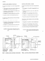
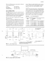
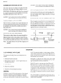
12 Make sure condensate dra]n line IStr~pped per irlstructlons
as mdlcated with Fitzure4.
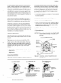
13. For shipping, the compressor hold-down nuts are
tightened, drawing the mounting feet down to the
shipping stops. After the unit is in its final position,
the four hold-down nuts must be removed to insert
the rubber grommets found in the small parts bag.
Replace the hold-down nuts and tighten until they
start to compress the isolator springs and then give
them an additional half turn.
NOTE: Stop air twlume dampers in “open”position.
b. Economizer dampers - refer to paragraph on “Economizer System” – (“Damper Linkage Adjustment”).
c, Exhaust air system - refer to paragraph on “Exhaust
Air System”.
WARNING: it is important that all panels at? ji~lo”secured with htches and screws beji)re tinit is
started.
Be sure that the ~taticpressure control accessory is installed at~dread>’to reguhte
the static pressure in the duct s?’stern,before starting the tinit blower.
22
Central Environmental Systems